US20080098254A1 - Method for Autonomous Dynamic Voltage and Frequency Scaling of Microprocessors - Google Patents
Method for Autonomous Dynamic Voltage and Frequency Scaling of Microprocessors Download PDFInfo
- Publication number
- US20080098254A1 US20080098254A1 US11/838,331 US83833107A US2008098254A1 US 20080098254 A1 US20080098254 A1 US 20080098254A1 US 83833107 A US83833107 A US 83833107A US 2008098254 A1 US2008098254 A1 US 2008098254A1
- Authority
- US
- United States
- Prior art keywords
- computer system
- microprocessor
- workload
- frequency
- voltage
- Prior art date
- Legal status (The legal status is an assumption and is not a legal conclusion. Google has not performed a legal analysis and makes no representation as to the accuracy of the status listed.)
- Granted
Links
Images


Classifications
-
- G—PHYSICS
- G06—COMPUTING; CALCULATING OR COUNTING
- G06F—ELECTRIC DIGITAL DATA PROCESSING
- G06F1/00—Details not covered by groups G06F3/00 - G06F13/00 and G06F21/00
- G06F1/26—Power supply means, e.g. regulation thereof
- G06F1/32—Means for saving power
- G06F1/3203—Power management, i.e. event-based initiation of a power-saving mode
- G06F1/3234—Power saving characterised by the action undertaken
- G06F1/324—Power saving characterised by the action undertaken by lowering clock frequency
-
- G—PHYSICS
- G06—COMPUTING; CALCULATING OR COUNTING
- G06F—ELECTRIC DIGITAL DATA PROCESSING
- G06F1/00—Details not covered by groups G06F3/00 - G06F13/00 and G06F21/00
- G06F1/26—Power supply means, e.g. regulation thereof
- G06F1/32—Means for saving power
- G06F1/3203—Power management, i.e. event-based initiation of a power-saving mode
- G06F1/3234—Power saving characterised by the action undertaken
- G06F1/3296—Power saving characterised by the action undertaken by lowering the supply or operating voltage
-
- Y—GENERAL TAGGING OF NEW TECHNOLOGICAL DEVELOPMENTS; GENERAL TAGGING OF CROSS-SECTIONAL TECHNOLOGIES SPANNING OVER SEVERAL SECTIONS OF THE IPC; TECHNICAL SUBJECTS COVERED BY FORMER USPC CROSS-REFERENCE ART COLLECTIONS [XRACs] AND DIGESTS
- Y02—TECHNOLOGIES OR APPLICATIONS FOR MITIGATION OR ADAPTATION AGAINST CLIMATE CHANGE
- Y02D—CLIMATE CHANGE MITIGATION TECHNOLOGIES IN INFORMATION AND COMMUNICATION TECHNOLOGIES [ICT], I.E. INFORMATION AND COMMUNICATION TECHNOLOGIES AIMING AT THE REDUCTION OF THEIR OWN ENERGY USE
- Y02D10/00—Energy efficient computing, e.g. low power processors, power management or thermal management
Definitions
- the present invention relates to the adaptive dynamic management of computer system operations, and more specifically to the dynamic voltage and frequency scaling (DVFS) of microprocessors.
- DVFS dynamic voltage and frequency scaling
- microprocessor performance gain is achieved by increasing the microprocessor (clock) frequency. But this goes along with the requirement of a higher effort in production and development costs, finally resulting in higher asset costs for computer systems. Permanent rise of the nominal frequency goes along with high requirements on cooling techniques and materials. Many microprocessor manufacturers dimension the maximal microprocessor frequency rather conservative to ensure operational stability and make some worst-case assumptions, so that for example environmental setups like those provided in air-conditioned rooms for huge server clusters are feasible.
- An important feature of contemporary microprocessors is the availability of a multitude of performance counters providing detailed information about workload characteristics, e.g. information about retired (completed) Instructions Per clock Cycle (IPC), processor cache misses, etc.
- IPC Instructions Per clock Cycle
- Nominal microprocessor frequencies used in computer systems are based on worst case assumptions concerning certain characteristics; e.g., ambient temperature and power demand of workloads.
- the microprocessor hardware allows frequencies that are significantly higher than the nominal frequencies.
- Thermal limitations are frequently alleviated by modern cooling techniques or an air conditioned setting of the system.
- Microprocessor power consumption depends significantly on the type of workload. However, in typical customer scenarios, the worst case assumptions do not occur simultaneously.
- a metric often used for workload characterization is the IPC number. It allows characterizing the microprocessor performance independent of its clock frequency.
- a method for prediction of workload phase duration and characterization is proposed in C. Isci et al “Long-Term Workload Phases: Duration Predictions and Applications to DVFS”, IEEE Micro, Vol. 25, 5/2005, pp. 39-51. That work mainly concentrates on a workload estimation using a last-value prediction.
- a gradient-based workload prediction technique based on linear regression is described in W. L. Bircher et al “Runtime Identification of Microprocessor Energy Saving Opportunities”, Proc. of the ILSPED 2005, pp. 275-280.
- Foxton technology as used in the Intel Itanium2 is an example for a mechanism used in contemporary microprocessors to increase frequency and voltage above the default values by using a temporary overdlocking on the chip level.
- Descriptions of the Foxton technology are given in R. McGowen et al “Power and temperature control on a 90-nm Itanium family processor” IEEE Journal of Solid State Signals Vol. 1, 1/2006, pp. 229-237 and T. Fischer et al “A 90-nm variable frequency clock system for a power-managed itanium architecture processor”, IEEE Journal of Solid State Signals Vol. 1, 1/2006, pp. 218-228.
- the advantages of the present invention are achieved by the autonomous detecting of phases of high microprocessor workload and prediction of their duration.
- the microprocessor frequency will be temporarily increased to an appropriate safe value (even beyond nominal frequency) consistent with technological and ambient constraints in order to improve performance when the computer system comprising the microprocessor benefits most, while during phases of low microprocessor workload its frequency and voltage will be decreased to save energy.
- This technique exploits hidden performance capabilities and improves the total performance of a computer system without compromising operational stability. No additional hardware such as service processors is needed for contemporary computer systems supporting performance counters and DFVS already.
- a method in accordance with the invention basically consists of steps for measurement, prediction and control in conjunction with a computer system comprising at least one microprocessor. More detailed, the method comprises the steps of:
- the invention allows significantly increasing the total computer system performance with only minimal impact on power consumption.
- FIG. 1 Is block diagram illustrating the system architecture of an embodiment of the invention
- FIG. 2 Is a graph of a function illustrating gradient-based workload duration prediction according to the invention
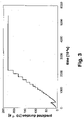
- FIG. 3 Is a graph of a workload phase duration prediction over time
- FIG. 4 Is a block diagram of a microprocessor power control loop according to the invention.
- FIG. 5 Is a block diagram of a microprocessor temperature control loop according to the invention.
- FIG. 6 Is a block diagram of a flow chart for a method in accordance with the invention.
- FIG. 7 Is a block diagram of a flow chart for a method in accordance with the invention.
- FIG. 8 Is a block diagram of a flow chart for a method in accordance with the invention.
- FIG. 9 Is a block diagram of a system in which certain embodiments may be implemented.
- FIG. 1 illustrates the system architecture of an embodiment of the invention in a computer system 100 .
- the embodiment is called TurboMode.
- a Xeon microprocessor is used as CPU (Central Processing Unit) 110 in the computer system 100 .
- the Xeon microprocessor can control its operation by using a set of MSRs (Model Specific Registers) 120 .
- a system management processor 130 controls the operation of the computer system 100 . It uses a set of hardware sensors 140 to monitor the hardware elements of the computer system 100 including the CPU 110 .
- the computer system 100 executes an instance of the Linux operating system with a Linux kernel 150 instance and various processes running in the user-level 160 of the Linux operating system.
- the Linux kernel 150 comprises various kernel modules that can especially create kernel threads that are running concurrently.
- the invention uses the AME (Autonomic Management of Energy) 170 kernel module and the timer facility 180 of the Linux kernel 150 .
- the timer 150 facility allows using Linux kernel timers—data structures that instruct the Linux kernel 150 to execute a user-defined function with a user-defined argument at a user-defined time. This function runs then asynchronously to the process that registered the timer.
- Typical resolutions for the Linux system timer 180 facility allow a maximal sampling frequency of 1 kHz for measurements.
- a TurboMode kernel module 190 implements a method in accordance with the present invention.
- An optional TurboMode monitoring process 200 in the user level 160 allows to present information about the current operational state of TurboMode to users of the computer system 100 .
- the TurboMode monitoring process 200 provides also a tracing facility to keep a logbook about the Turbomode operational state.
- the interface to the tracing facility is realized via entries in the Linux proc filesystem.
- the AME 170 kernel module provides interfaces for sensor data measurements, which are used by the TurboMode kernel module 190 to read sensor data from the sensors 140 .
- the timer facility 180 periodically calls the TurboMode kernel module 190 to sample sensor data for the sensor 140 , for which it uses a separate kernel thread.
- FIG. 1 BladeCenter Chassis Two different Xeon microprocessors were used: The Intel Xeon Nocona and the Intel xeon Irwindale. Both microprocessors have a nominal frequency of 3.6 GHz.
- the system management processor 130 is implemented by the Hitachi H8S 2166 service processor.
- the AME 170 accesses the sensors 140 via I/O (input/output) ports from the system management processor 130 , which are made accessible for reading by the TurboMode kernel module 190 .
- This allows a fast access to sensor data, which is required for high sampling frequencies and results in better operating stability and higher granularity for dynamic changes.
- a sampling interval of 10 ms for the sensor data turned out to be sufficient for this environment for the sampling kernel thread of the TurboMode kernel module 190 .
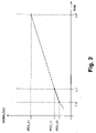
- FIG. 2 illustrates the gradient-based prediction of IPC values as used for the workload phase duration prediction according to the present invention.
- Previously measured IPC values IPC(t_ 0 ), IPC(t_ 1 )
- IPC(t_ 1 ) are used to calculate the gradient for the previous duration interval (t_ 1 ⁇ t_ 0 ).
- This gradient is applied to predict the IPC values for the next duration interval (t 2 ⁇ t 1 ).
- a prediction for a future IPC(t_ 2 ) is then calculated as follows:
- IPC ⁇ ( t_ ⁇ 2 ) IPC ⁇ ( t_ ⁇ 1 ) + IPC ⁇ ( t_ ⁇ 1 ) - IPC ⁇ ( t_ ⁇ 0 ) t_ ⁇ 0 - t_ ⁇ 0 ⁇ ( t_ ⁇ 2 - t_ ⁇ 1 )
- the basic rationale for predicting the duration is that if a specific number of consecutive measured IPC values lies within a specified window, the IPC can be declared as stable, which means that it follows a constant progression. So if this number of stable samples is seen, the assumption can be made that a particular amount of further samples lying in the stability window will be seen. With an increasing number of consecutive stable samples, the predicted number of following samples also rises.
- This algorithm can be described as follows:
- MED ⁇ ( ipc ⁇ ( t_ ⁇ ( now - M / 2 ) ) ) MED ⁇ ⁇ ipc ⁇ ( t_ ⁇ ( now - M ) ) ; ipc ⁇ ( t_ ⁇ ( now - M / 2 ) ) ; ipc ⁇ ( t_now ) ⁇
- the TurboMode kernel module 190 implements a DVFS method in accordance with the present invention.
- Frequency and voltage of a microprocessor cannot be set independently and only to discrete values.
- a P-State (performance state) model defines available frequencies and voltages for a microprocessor in a lookup table to have discrete values for a fixed amount of states. In order to modify current operating frequency and voltage of the microprocessor, it can be transferred to a different P-State. For microprocessors supporting DVFS a bigger granularity of P-State definitions can be used in order to improve power control quality.
- Microprocessor power consumption has to be controlled during high IPC phases to guarantee operational safety of the computer system and not to damage hardware.
- power consumption should be as small as possible. Therefore, microprocessor frequency and voltage are set to their defaults values during phases of normal IPC, and even scaled down for phases of low IPC in order to save energy. Only during phases when the TurboMode kernel module 190 triggers a frequency boost, a power control loop must ensure that the power consumption stays within its limits.
- FIG. 4 illustrates schematically the functionality for such a power control loop 400 .
- P MAX maximal permanent power value
- P ACTUAL the maximal permanent power value
- e the difference between P MAX and P ACTUAL
- the result is a value ⁇ fv 2 that describes how much the product of the frequency and the squared voltage should be changed from its current value.
- the valve of the control loop 400 is the lookup table LUT that maps the output of the PID controller to discrete absolute frequency f and voltage v values that are fed into the microprocessor and will result into a new actual power P ACTUAL consisting of a dynamic part P and a constant static part P STATIC .
- This new power value P ACTUAL will be measured at the start of the next sampling interval defined by a value ⁇ t.
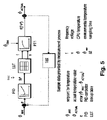
- FIG. 5 illustrates schematically the functionality of a temperature control loop 500 in accordance with the invention.
- the control loop 500 uses the PFi), the LUT and the sampling interval of the power control loop 400 .
- V MAX is used as the setpoint for the control.
- the error e for the difference between V MAX and V ACTUAL is used as the input for the PID controller to calculate the output depending on the specified parameters of the PID controller
- the result is a value fv 2 that describes the product of the frequency and the squared voltage. With the lookup table LUT this value is transformed into a discrete frequency f and voltage v pair.
- the valve of the control loop 500 is the lookup table LUT that maps the output of the PID controller to discrete absolute frequency f and voltage v values that are fed into the microprocessor and will result into a new actual temperature V ACTUAL depending on the current environmental temperature V RNV .
- This new temperature value V ACTUAL will be measured at the start of the next sampling interval defined by the value ⁇ t.
- the PID controller is implemented by the TurboMode kernel module 190 with the help of the AME 170 kernel module and the MSRs 120 of the Xeon microprocessor.
- the PID controller separates current status of the computer system 100 basically between three different states for the CPU 110 : idle, normal, and high IPC phases.
- An indication for an idle phase is determined by the calculation of an activity factor of the CPU 110 describing its utilization.
- the activity factor is the number of clock cycles where the CPU 110 is not halted divided by the number of all clock cycles during a sampling interval. If the activity factor drops below a specific threshold, the CPU 110 will be set by the TurboMode kernel module 190 to the P-State used for the idle phase. In this case, the microprocessor frequency and voltage of the CPU 110 are set to the lowest possible P-State in order to save energy.
- For the detection and treatment of idle phases also well-known methods to reduce microprocessor power consumption can be used.
- microprocessor frequency and voltage are set to their default P-State in order to allow standard operational behaviour of the CPU 110 .
- Microprocessor power and temperature control is not active during idle or normal IPC phases as power and temperature limits for the microprocessor cannot be reached.
- the TurboMode kernel module 190 sets microprocessor frequency and voltage of the CPU 110 to a P-State that allows a performance boost for the CPU 110 . For this P-State the power and control loop needs to ensure that power and temperature limits are not exceeded in order to prevent hardware damages and malfunctions.
- the invention can be extended to multiple CPUs in the computer system 100 .
- a separate power and temperature control loop can be used for every CPU or the same power and temperature control loop can be used for all CPUs.
- a Linux kernel timer is configured to execute a specific function of the TurboMode kernel module 190 .
- This function triggers a sleeping sampling kernel thread to perform measurement and prediction and configuring the Linux kernel timer for the next triggering after same interval of time (sampling interval). This way a periodic rescheduling process of the sampling kernel thread is achieved. This rescheduling process is continued until a specified number of samples have been collected. Then a tracing thread created by the TurboMode kernel module 190 is triggered to write the collected measurement and prediction data into a trace tile.
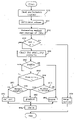
- FIG. 6 shows the general control flow for the sampling kernel thread.
- step 600 it is determined if the sampling thread was triggered by the Linux kernel timer. If not, the sampling kernel thread is sleeping in step 610 until it will be triggered by the Linux kernel timer. If the sampling kernel thread was triggered (step 600 ), sensor data is read from the AME 170 kernel module in step 620 . The collected sensor data is then used in step 630 together with the content of the MSRs 120 to predict the IPC. In step 640 it will be determined if the tracing thread needs to be triggered in case tracing is enabled.
- step 650 it will be checked if the sampling kernel thread needs to be cancelled in case the Linux kernel 150 has sent a kill signal to the sampling kernel thread If no kill signal was received, then the Linux kernel timer will be set up to trigger execution of the sampling thread after the sampling time has elapsed.
- Reading sensor data via the AME 170 kernel module is a measurement for the entire computer system 100 and therefore does not depend on the number of CPUs (in case there are more CPUs than the single CPU 110 ). In the very first sampling of sensor data no prediction will be performed.
- FIG. 7 provides a more detailed control flow for the collection of the sensor data for the following iterations.
- step 700 it will be tested, if the AME recording bit provided by the AME 170 kernel module is set. If so, no new sensor data is provided by the AME 170 kernel module and the old values will be kept in step 710 . Otherwise the I/O ports provided by the AME 170 kernel module are read in step 720 . In step 730 it is determined if power and temperature relevant sensor data has not changed.
- step 740 If so, then the old values will be kept in step 740 . Otherwise it will be checked in step 750 if the number of new sensor data is equal to the time difference between the current and the last sampling. If not, then in step 760 the sensor data from the previous sampling time will be used instead of the sensor data from the current sampling time. Finally, in step 770 the new power and temperature values will be calculated.
- the power related sensor data can be the energy consumption of the CPU 110 . Then the new power value is calculated by dividing the difference of the energy consumption by the time interval. In order to improve performance, the measurement can be performed separately and concurrently on each CPU.
- the control flow for the Xeon microprocessor performance counter measurement and the IPC prediction is shown in FIG. 8 .
- the very first step is omitted as only the performance counter values can be collected.
- the calculation of basic metrics like IPC, frequency and processor cache misses per cycle (CMPC) is performed after the collection of the performance counter values.
- the performance counter values are collected from the MSRs 120 .
- the metrics are calculated in step 810 .
- the median value and the average of the IPC are calculated in step 820 .
- step 830 it will be checked if the number of samples to he collected until the next prediction has to be performed is equal 0. If so, then the old prediction values will be kept in step 890 . Otherwise stability criteria for the CPU 110 will be tested in step 840 . These stability criteria are defined as follows: The current median value of the IPC must not deviate from the previous value by more than a predefined value, and the current IPC value must not deviate from the previous value by more than a predefined value.
- step 850 it will be checked if stability criteria for the IPC are fulfilled. If not, then the predicted values are reset in step 891 . Otherwise it will be checked in step 860 if a prediction of the IPC was performed earlier. If so, then this prediction will be tested in step 870 for a maximal tolerance interval. This tolerance interval is given by the absolute difference to the current average of the IPC. If the previous prediction is not within the maximal tolerance interval, then it will be reset in step 891 . Otherwise it will be used for the prediction in step 892 . If no previous prediction of the IPC was detected in step 860 , then it will be checked in step 880 if enough samples are available for a prediction. If so, then they will be used for the prediction in step 892 . Otherwise further samples will be collected in step 893 .
- step 894 if the computer system 100 would benefit from a performance boost for the CPU 110 . This is performed by checking whether the current predicted IPC and its duration exceeds a specified threshold. If so, a frequency boost for the CPU 110 will be initiated. On a currently running frequency boost, it will be tested, if the IPC has dropped down below a lower threshold for an amount of specified samples to stop the frequency boost. If a frequency boost can be applied, a flag will be set to indicate this to the control loop.
- Another embodiment for the invention could be an implementation as part of a Hypervisor, which is a scheme allowing multiple operating systems to run, unmodified, on a computer system at the same time. Also performance counters can be provided by other facilities such as Hypervisors or workload managers.
- the described techniques may be implemented as a method, apparatus or article of manufacture involving software, firmware, micro-code, hardware and/or any combination thereof.
- article of manufacture refers to code or logic implemented in a medium, where such medium may comprise hardware logic [e.g., an integrated circuit chip, Programmable Gate Array (PGA), Application Specific Integrated Circuit (ASIC), etc.] or a computer readable medium, such as magnetic storage medium (e.g., hard disk drives, floppy disks, tape, etc.), optical storage (CD-ROMs, optical disks, etc.), volatile and non-volatile memory devices [e.g., Electrically Erasable Programmable Read Only Memory (EEPROM), Read Only Memory (ROM), Programmable Read Only Memory (PROM), Random Access Memory (RAM), Dynamic Random Access Memory (DRAM), Static Random Access Memory (SRAM), flash, firmware, programmable logic, etc.].
- EEPROM Electrically Erasable Programmable Read Only Memory
- ROM Read Only Memory
- PROM Programmable Read Only Memory
- RAM
- Code in the computer readable medium is accessed and executed by a processor.
- the medium in which the code or logic is encoded may also comprise transmission signals propagating through space or a transmission media, such as an optical fiber, copper wire, etc.
- the transmission signal in which the code or logic is encoded may further comprise a wireless signal, satellite transmission, radio waves, infrared signals, Bluetooth, etc.
- the transmission signal in which the code or logic is encoded is capable of being transmitted by a transmitting station and received by a receiving station, where the code or logic encoded in the transmission signal may be decoded and stored in hardware or a computer readable medium at the receiving and transmitting stations or devices.
- the “article of manufacture” may comprise a combination of hardware and software components in which the code is embodied, processed, and executed.
- the article of manufacture may comprise any information bearing medium.
- the article of manufacture comprises a storage medium having stored therein instructions that when executed by a machine results in operations being performed.
- Certain embodiments can take the form of an entirely hardware embodiment, an entirely software embodiment or an embodiment containing both hardware and software elements.
- the invention is implemented in software, which includes but is not limited to firmware, resident software, microcode, etc.
- certain embodiments can take the form of a computer program product accessible from a computer usable or computer readable medium providing program code for use by or in connection with a computer or any instruction execution system.
- a computer usable or computer readable medium can be any apparatus that can contain, store, communicate, propagate, or transport the program for use by or in connection with the instruction execution system, apparatus, or device.
- the medium can be an electronic, magnetic, optical, electromagnetic, infrared, or semiconductor system (or apparatus or device) or a propagation medium.
- Examples of a computer-readable medium include a semiconductor or solid state memory, magnetic tape, a removable computer diskette, a random access memory (RAN), a read-only memory (ROM), a rigid magnetic disk and an optical disk. Current examples of optical disks include compact disk—read only memory (CD-ROM), compact disk—read/write (CD-R/W) and DVD.
- Devices that are in communication with each other need not be in continuous communication with each other, unless expressly specified otherwise.
- devices that are in communication with each other may communicate directly or indirectly through one or more intermediaries.
- a description of an embodiment with several components in communication with each other does not imply that all such components are required. On the contrary a variety of optional components are described to illustrate the wide variety of possible embodiments.
- process steps, method steps, algorithms or the like may be described in a sequential order, such processes, methods and algorithms may be configured to work in alternate orders.
- any sequence or order of steps that may be described does not necessarily indicate a requirement that the steps be performed in that order.
- the steps of processes described herein may be performed in any order practical. Further, some steps may be performed simultaneously, in parallel, or concurrently.
- FIG. 9 illustrates a block diagram of a computer system 900 in which certain embodiments may be implemented.
- the system 900 may include a circuitry 902 that may in certain embodiments include a microprocessor 904 .
- the computer system 900 may also include a memory 906 (e.g., a volatile memory device), and storage 908 .
- the storage 908 may include a non-volatile memory device (e.g., EEPROM, ROM, PROM, RAM, DRAM, SRAM, flash, firmware, programmable logic, etc.), magnetic disk drive, optical disk drive, tape drive, etc.
- the storage 908 may comprise an internal storage device, an attached storage device and/or a network accessible storage device.
- the system 900 may include a program logic 910 including code 912 that may be loaded into the memory 906 and executed by the microprocessor 904 or circuitry 902 .
- the program logic 910 including code 912 may be stored in the storage 908 .
- the program logic 910 may be implemented in the circuitry 902 . Therefore, while FIG. 9 shows the program logic 910 separately from the other elements, the program logic 910 may be implemented in the memory 906 and/or the circuitry 902 .
- Certain embodiments may be directed to a method for deploying computing instruction by a person or automated processing integrating computer-readable code into a computing system, wherein the code in combination with the computing system is enabled to perform the operations of the described embodiments.
Abstract
Description
- The present invention relates to the adaptive dynamic management of computer system operations, and more specifically to the dynamic voltage and frequency scaling (DVFS) of microprocessors.
- Generally, microprocessor performance gain is achieved by increasing the microprocessor (clock) frequency. But this goes along with the requirement of a higher effort in production and development costs, finally resulting in higher asset costs for computer systems. Permanent rise of the nominal frequency goes along with high requirements on cooling techniques and materials. Many microprocessor manufacturers dimension the maximal microprocessor frequency rather conservative to ensure operational stability and make some worst-case assumptions, so that for example environmental setups like those provided in air-conditioned rooms for huge server clusters are feasible.
- Power consumption and the associated heat generation of modern microprocessors are key design issues in the development process of computer systems, especially when the available space is very limited like in desktop systems or blade centers. Many mechanisms exist in contemporary microprocessors to vary its power consumption, e.g. by explicitly decreasing or increasing frequency and voltage. Many modern microprocessors provide such DVFS mechanisms. Enhanced SpeedStep is one of those and supported by various Intel microprocessors.
- An important feature of contemporary microprocessors is the availability of a multitude of performance counters providing detailed information about workload characteristics, e.g. information about retired (completed) Instructions Per clock Cycle (IPC), processor cache misses, etc.
- Nominal microprocessor frequencies used in computer systems are based on worst case assumptions concerning certain characteristics; e.g., ambient temperature and power demand of workloads. In general, the microprocessor hardware allows frequencies that are significantly higher than the nominal frequencies. Thermal limitations are frequently alleviated by modern cooling techniques or an air conditioned setting of the system. Microprocessor power consumption depends significantly on the type of workload. However, in typical customer scenarios, the worst case assumptions do not occur simultaneously.
- Various approaches to autonomously reduce microprocessor power consumption exist when there has been no or little system utilization detected for some period of time. A metric often used for workload characterization is the IPC number. It allows characterizing the microprocessor performance independent of its clock frequency. A method for prediction of workload phase duration and characterization is proposed in C. Isci et al “Long-Term Workload Phases: Duration Predictions and Applications to DVFS”, IEEE Micro, Vol. 25, 5/2005, pp. 39-51. That work mainly concentrates on a workload estimation using a last-value prediction. A gradient-based workload prediction technique based on linear regression is described in W. L. Bircher et al “Runtime Identification of Microprocessor Energy Saving Opportunities”, Proc. of the ILSPED 2005, pp. 275-280.
- The so-called Foxton technology as used in the Intel Itanium2 is an example for a mechanism used in contemporary microprocessors to increase frequency and voltage above the default values by using a temporary overdlocking on the chip level. Descriptions of the Foxton technology are given in R. McGowen et al “Power and temperature control on a 90-nm Itanium family processor” IEEE Journal of Solid State Signals Vol. 1, 1/2006, pp. 229-237 and T. Fischer et al “A 90-nm variable frequency clock system for a power-managed itanium architecture processor”, IEEE Journal of Solid State Signals Vol. 1, 1/2006, pp. 218-228.
- Existing DVFS solutions mainly focus on the improvement of microprocessor energy efficiency and not boosting of its performance. They optimize microprocessor power consumption with only minimal impact on the performance of the workload currently executed by the microprocessor.
- It is therefore an object of the present invention to provide a method for autonomous DVFS of a microprocessor that is improved over the prior art, and a corresponding computer program and computer program product, and a corresponding computer system.
- The advantages of the present invention are achieved by the autonomous detecting of phases of high microprocessor workload and prediction of their duration. The microprocessor frequency will be temporarily increased to an appropriate safe value (even beyond nominal frequency) consistent with technological and ambient constraints in order to improve performance when the computer system comprising the microprocessor benefits most, while during phases of low microprocessor workload its frequency and voltage will be decreased to save energy. This technique exploits hidden performance capabilities and improves the total performance of a computer system without compromising operational stability. No additional hardware such as service processors is needed for contemporary computer systems supporting performance counters and DFVS already.
- A method in accordance with the invention basically consists of steps for measurement, prediction and control in conjunction with a computer system comprising at least one microprocessor. More detailed, the method comprises the steps of:
-
- collecting and storing performance data of said computer system during a period of time;
- predicting future workload metrics and their duration for said computer system from the stored performance data, and classifying the current workload for said computer system at least in phases of normal and high workload based on the predicted future workload metrics and their predicted duration;
- modifying parameters of said computer system suitable to increase the frequency and voltage of said microprocessor for current workloads classified as a phase of high workload;
- modifying frequency and voltage of said microprocessor to their normal values for current workloads classified as a phase of normal workload
- In the preferred embodiment of the invention the following steps are iterated at a specified sampling interval, recording data to obtain previously calculated values:
-
- calculating the power consumption P of the computer system comprising the microprocessor during the most recent sampling interval (t_n−1, t_n), dividing the difference of the total aggregated energy values at time t_n and t_n−1 by the sampling interval duration;
- measuring the microprocessor temperature;
- calculating the current IPC of the microprocessor by using its performance counters;
- predicting microprocessor workload phase characteristics based on the current IPC;
- checking whether a prediction for the current IPC exists;
- if a prediction exists, keeping the predicted value and previous workload classifications, otherwise checking whether a prediction should be performed by applying an appropriate stability criteria;
- if no new prediction should be performed, invalidating all predicted values, classifying the workload as normal, otherwise checking whether a prediction for the previous sampling time from a previous prediction exists;
- if a prediction for the previous sampling time exists, checking whether the prediction for the previous sampling time deviates less than a specified value from the current IPC and if not, invalidating all predicted values and classifying the current workload as normal;
- if no prediction for the previous sampling time exists, determining whether enough previously measured samples have been collected for a prediction, and if not, keeping the predicted values and previous workload classification, otherwise performing a prediction for the duration of the current workload phase, predicting the IPC for the current workload phase, and classifying the predicted workload in idle, normal, and high workloads;
- if the predicted workload is idle, setting the microprocessor frequency and voltage to the minimum allowed values;
- if the predicted workload is normal, setting the microprocessor frequency and voltage to their nominal values;
- if the predicted workload is high, activating a control feedback loop circuit to set the microprocessor frequency and voltage autonomously according to power or temperature setpoints in order to prevent hardware damages or malfunctions.
- The invention allows significantly increasing the total computer system performance with only minimal impact on power consumption.
- The present invention and its advantages are now described in conjunction with the accompanying drawings.
-
FIG. 1 : Is block diagram illustrating the system architecture of an embodiment of the invention; -
FIG. 2 : Is a graph of a function illustrating gradient-based workload duration prediction according to the invention; -
FIG. 3 : Is a graph of a workload phase duration prediction over time; -
FIG. 4 : Is a block diagram of a microprocessor power control loop according to the invention; -
FIG. 5 : Is a block diagram of a microprocessor temperature control loop according to the invention; -
FIG. 6 : Is a block diagram of a flow chart for a method in accordance with the invention; -
FIG. 7 : Is a block diagram of a flow chart for a method in accordance with the invention; -
FIG. 8 : Is a block diagram of a flow chart for a method in accordance with the invention; -
FIG. 9 : Is a block diagram of a system in which certain embodiments may be implemented. - TurboMode
-
FIG. 1 illustrates the system architecture of an embodiment of the invention in acomputer system 100. The embodiment is called TurboMode. A Xeon microprocessor is used as CPU (Central Processing Unit) 110 in thecomputer system 100. The Xeon microprocessor can control its operation by using a set of MSRs (Model Specific Registers) 120. Asystem management processor 130 controls the operation of thecomputer system 100. It uses a set ofhardware sensors 140 to monitor the hardware elements of thecomputer system 100 including theCPU 110. Thecomputer system 100 executes an instance of the Linux operating system with aLinux kernel 150 instance and various processes running in the user-level 160 of the Linux operating system. - The
Linux kernel 150 comprises various kernel modules that can especially create kernel threads that are running concurrently. The invention uses the AME (Autonomic Management of Energy) 170 kernel module and thetimer facility 180 of theLinux kernel 150. Thetimer 150 facility allows using Linux kernel timers—data structures that instruct theLinux kernel 150 to execute a user-defined function with a user-defined argument at a user-defined time. This function runs then asynchronously to the process that registered the timer. Typical resolutions for theLinux system timer 180 facility allow a maximal sampling frequency of 1 kHz for measurements. - A
TurboMode kernel module 190 implements a method in accordance with the present invention. An optionalTurboMode monitoring process 200 in the user level 160 allows to present information about the current operational state of TurboMode to users of thecomputer system 100. TheTurboMode monitoring process 200 provides also a tracing facility to keep a logbook about the Turbomode operational state. The interface to the tracing facility is realized via entries in the Linux proc filesystem. TheAME 170 kernel module provides interfaces for sensor data measurements, which are used by theTurboMode kernel module 190 to read sensor data from thesensors 140. Thetimer facility 180 periodically calls theTurboMode kernel module 190 to sample sensor data for thesensor 140, for which it uses a separate kernel thread. - A potential implementation for the
computer system 100 is described in the IBM Research Report RC23835 (W0512-086), Dec. 19, 2005: X. Wang et al “Managing Peak System-level Power with Feedback Control”. An IBM BladeCenter comprises multiple HS20 blades with Intel Xeon processors. The power management is shown there inFIG. 1 BladeCenter Chassis. Two different Xeon microprocessors were used: The Intel Xeon Nocona and the Intel xeon Irwindale. Both microprocessors have a nominal frequency of 3.6 GHz. - The
system management processor 130 is implemented by the Hitachi H8S 2166 service processor. TheAME 170 accesses thesensors 140 via I/O (input/output) ports from thesystem management processor 130, which are made accessible for reading by theTurboMode kernel module 190. This allows a fast access to sensor data, which is required for high sampling frequencies and results in better operating stability and higher granularity for dynamic changes. A sampling interval of 10 ms for the sensor data turned out to be sufficient for this environment for the sampling kernel thread of theTurboMode kernel module 190. - Workload Prediction
-
FIG. 2 illustrates the gradient-based prediction of IPC values as used for the workload phase duration prediction according to the present invention. Previously measured IPC values (IPC(t_0), IPC(t_1)) are used to calculate the gradient for the previous duration interval (t_1−t_0). This gradient is applied to predict the IPC values for the next duration interval (t2−t1). A prediction for a future IPC(t_2) is then calculated as follows: -
- The basic rationale for predicting the duration is that if a specific number of consecutive measured IPC values lies within a specified window, the IPC can be declared as stable, which means that it follows a constant progression. So if this number of stable samples is seen, the assumption can be made that a particular amount of further samples lying in the stability window will be seen. With an increasing number of consecutive stable samples, the predicted number of following samples also rises.
- A number of consecutive stable samples (X0) are required to perform a first prediction, where stability is defined by the criterion that each sample has to lie within a predefined threshold to each other. It is assumed that if Xn samples are seen (X0 on first iteration), Xn+1 further samples within the stability criterion will follow. This process is iterated until the maximal allowed prediction duration is reached or a single sample falls out of the stability criterion. In the first case, the predicted duration is kept at its previous value (Xn+1=Xn) in the second one it is reset to X0. This algorithm can be described as follows:
-
- Measurements based on Standard Performance Evaluation Corporation (SPEC)
CPU 2000 benchmark results have shown that good results can be achieved with S:=8. In this case the algorithm starts with an initial number of 8 subsequent stable samples, which are required to do a first prediction. Then, a prediction is made that nine further stable samples will be seen. If during these nine samples no sample fails out of the stability window, the next prediction will be performed, estimating that another ten samples will match the stability criterion This process will be iterated until a single sample will fall out the window and deviates more than specified by the limit from the measured IPC. An example phase duration prediction graph using this algorithm is shown inFIG. 2 . - Measurements for a TurboMode implementation in an IBM BlaceCenter computer system similar to the one described earlier have shown that samples fall out of the window occasionally due to IPC measurement failures caused by timing problems or noises on the IPC induced by running background processes in the user-level 160 and kernel threads in the
Linux kernel 150 of the Linux operating system. Timing problems even led to short but huge outliers that corrupt gradient calculation. Because the Linux kernel running on the IBM HS20 blades in the IBM BladeCenter had no hard real-time support, this problem may not be eliminated. Therefore, the median value of the current IPCs is calculated as well as their average. The median is the 50-percentile of a data series. It can be determined by sorting the series by value and picking the one from the middle. The advantage of the median value lies in its capability to filter even huge outliers. - To get the median value of the actual workload, the values for following IPCs would be required. This is impossible and estimated results would even lead to a bigger process error. So on calculation the median of the IPC M/2 samples ago is received as illustrated in the following equation for M=3:
-
- A similar problem occurs at the average calculation, but this can be directly influenced as the new measured value is not filtered. This leads then to the problem that also outliers are not filtered in such a good way like they are with the median. M/2 sample intervals (t_Y-t_X) are needed for the median to recognize that a jump of the measured IPC occurred, whereas the average instantly reacts but suffers on the slow replacement of the old values in its buffer. This leads to an immoderate smoothing of the measurements and can cause overshoots in gradient calculation. Therefore, the number of samples used for gradient calculation should be greater than the amount of samples taken in the period of median phase shift (t_y-t_x). In order to get a compromise, both values will be used for the improvement of the measured IPC. The median values are used for gradient calculation, while the average values are utilized to calculate the deviation between the predicted and the measured IPC.
- Power and Temperature Control
- The
TurboMode kernel module 190 implements a DVFS method in accordance with the present invention. Frequency and voltage of a microprocessor cannot be set independently and only to discrete values. A P-State (performance state) model defines available frequencies and voltages for a microprocessor in a lookup table to have discrete values for a fixed amount of states. In order to modify current operating frequency and voltage of the microprocessor, it can be transferred to a different P-State. For microprocessors supporting DVFS a bigger granularity of P-State definitions can be used in order to improve power control quality. - Microprocessor power consumption has to be controlled during high IPC phases to guarantee operational safety of the computer system and not to damage hardware. During phases of low or normal microprocessor workloads, power consumption should be as small as possible. Therefore, microprocessor frequency and voltage are set to their defaults values during phases of normal IPC, and even scaled down for phases of low IPC in order to save energy. Only during phases when the
TurboMode kernel module 190 triggers a frequency boost, a power control loop must ensure that the power consumption stays within its limits. - According to the invention, either temperature or power will be controlled by a control feedback loop.
FIG. 4 illustrates schematically the functionality for such apower control loop 400. As the setpoint for the control the maximal permanent power value PMAX is used. The error e for the difference between PMAX and PACTUAL is used as the input for a PID controller to calculate the output depending on the specified parameters of the PID controller. The result is a value Δfv2 that describes how much the product of the frequency and the squared voltage should be changed from its current value. With a lookup table LUT this value is transformed into a discrete frequency f and voltage v pair as the new settings for the microprocessor. The valve of thecontrol loop 400 is the lookup table LUT that maps the output of the PID controller to discrete absolute frequency f and voltage v values that are fed into the microprocessor and will result into a new actual power PACTUAL consisting of a dynamic part P and a constant static part PSTATIC. This new power value PACTUAL will be measured at the start of the next sampling interval defined by a value Δt. -
FIG. 5 illustrates schematically the functionality of atemperature control loop 500 in accordance with the invention. Thecontrol loop 500 uses the PFi), the LUT and the sampling interval of thepower control loop 400. As the setpoint for the control the maximal permanent temperature value VMAX is used. The error e for the difference between VMAX and VACTUAL is used as the input for the PID controller to calculate the output depending on the specified parameters of the PID controller The result is a value fv2 that describes the product of the frequency and the squared voltage. With the lookup table LUT this value is transformed into a discrete frequency f and voltage v pair. The valve of thecontrol loop 500 is the lookup table LUT that maps the output of the PID controller to discrete absolute frequency f and voltage v values that are fed into the microprocessor and will result into a new actual temperature VACTUAL depending on the current environmental temperature VRNV. This new temperature value VACTUAL will be measured at the start of the next sampling interval defined by the value Δt. - In the preferred embodiment of the present invention, the PID controller is implemented by the
TurboMode kernel module 190 with the help of theAME 170 kernel module and theMSRs 120 of the Xeon microprocessor. The PID controller separates current status of thecomputer system 100 basically between three different states for the CPU 110: idle, normal, and high IPC phases. An indication for an idle phase is determined by the calculation of an activity factor of theCPU 110 describing its utilization. The activity factor is the number of clock cycles where theCPU 110 is not halted divided by the number of all clock cycles during a sampling interval. If the activity factor drops below a specific threshold, theCPU 110 will be set by theTurboMode kernel module 190 to the P-State used for the idle phase. In this case, the microprocessor frequency and voltage of theCPU 110 are set to the lowest possible P-State in order to save energy. For the detection and treatment of idle phases also well-known methods to reduce microprocessor power consumption can be used. - During normal IPC phases, microprocessor frequency and voltage are set to their default P-State in order to allow standard operational behaviour of the
CPU 110. Microprocessor power and temperature control is not active during idle or normal IPC phases as power and temperature limits for the microprocessor cannot be reached. During phases with high IPC, theTurboMode kernel module 190 sets microprocessor frequency and voltage of theCPU 110 to a P-State that allows a performance boost for theCPU 110. For this P-State the power and control loop needs to ensure that power and temperature limits are not exceeded in order to prevent hardware damages and malfunctions. - The invention can be extended to multiple CPUs in the
computer system 100. In that case, a separate power and temperature control loop can be used for every CPU or the same power and temperature control loop can be used for all CPUs. - Measurement and Prediction
- A Linux kernel timer is configured to execute a specific function of the
TurboMode kernel module 190. This function triggers a sleeping sampling kernel thread to perform measurement and prediction and configuring the Linux kernel timer for the next triggering after same interval of time (sampling interval). This way a periodic rescheduling process of the sampling kernel thread is achieved. This rescheduling process is continued until a specified number of samples have been collected. Then a tracing thread created by theTurboMode kernel module 190 is triggered to write the collected measurement and prediction data into a trace tile. -
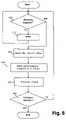
FIG. 6 shows the general control flow for the sampling kernel thread. Instep 600 it is determined if the sampling thread was triggered by the Linux kernel timer. If not, the sampling kernel thread is sleeping instep 610 until it will be triggered by the Linux kernel timer. If the sampling kernel thread was triggered (step 600), sensor data is read from theAME 170 kernel module instep 620. The collected sensor data is then used instep 630 together with the content of the MSRs 120 to predict the IPC. Instep 640 it will be determined if the tracing thread needs to be triggered in case tracing is enabled. Instep 650 it will be checked if the sampling kernel thread needs to be cancelled in case theLinux kernel 150 has sent a kill signal to the sampling kernel thread If no kill signal was received, then the Linux kernel timer will be set up to trigger execution of the sampling thread after the sampling time has elapsed. - Reading sensor data via the
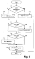
AME 170 kernel module is a measurement for theentire computer system 100 and therefore does not depend on the number of CPUs (in case there are more CPUs than the single CPU 110). In the very first sampling of sensor data no prediction will be performed.FIG. 7 provides a more detailed control flow for the collection of the sensor data for the following iterations. Instep 700 it will be tested, if the AME recording bit provided by theAME 170 kernel module is set. If so, no new sensor data is provided by theAME 170 kernel module and the old values will be kept instep 710. Otherwise the I/O ports provided by theAME 170 kernel module are read instep 720. Instep 730 it is determined if power and temperature relevant sensor data has not changed. If so, then the old values will be kept instep 740. Otherwise it will be checked instep 750 if the number of new sensor data is equal to the time difference between the current and the last sampling. If not, then instep 760 the sensor data from the previous sampling time will be used instead of the sensor data from the current sampling time. Finally, instep 770 the new power and temperature values will be calculated. - For example, the power related sensor data can be the energy consumption of the
CPU 110. Then the new power value is calculated by dividing the difference of the energy consumption by the time interval. In order to improve performance, the measurement can be performed separately and concurrently on each CPU. - The control flow for the Xeon microprocessor performance counter measurement and the IPC prediction is shown in
FIG. 8 . As with the reading of the sensor data, the very first step is omitted as only the performance counter values can be collected. On the subsequent iterations the calculation of basic metrics like IPC, frequency and processor cache misses per cycle (CMPC) is performed after the collection of the performance counter values. Instep 800 the performance counter values are collected from theMSRs 120. The metrics are calculated instep 810. The median value and the average of the IPC are calculated instep 820. - In
step 830 it will be checked if the number of samples to he collected until the next prediction has to be performed is equal 0. If so, then the old prediction values will be kept instep 890. Otherwise stability criteria for theCPU 110 will be tested instep 840. These stability criteria are defined as follows: The current median value of the IPC must not deviate from the previous value by more than a predefined value, and the current IPC value must not deviate from the previous value by more than a predefined value. - In
step 850 it will be checked if stability criteria for the IPC are fulfilled. If not, then the predicted values are reset in step 891. Otherwise it will be checked instep 860 if a prediction of the IPC was performed earlier. If so, then this prediction will be tested instep 870 for a maximal tolerance interval. This tolerance interval is given by the absolute difference to the current average of the IPC. If the previous prediction is not within the maximal tolerance interval, then it will be reset in step 891. Otherwise it will be used for the prediction instep 892. If no previous prediction of the IPC was detected instep 860, then it will be checked instep 880 if enough samples are available for a prediction. If so, then they will be used for the prediction instep 892. Otherwise further samples will be collected instep 893. - After prediction is done (subsequent to the
steps 891, 892, 893) it will be determined instep 894 if thecomputer system 100 would benefit from a performance boost for theCPU 110. This is performed by checking whether the current predicted IPC and its duration exceeds a specified threshold. If so, a frequency boost for theCPU 110 will be initiated. On a currently running frequency boost, it will be tested, if the IPC has dropped down below a lower threshold for an amount of specified samples to stop the frequency boost. If a frequency boost can be applied, a flag will be set to indicate this to the control loop. - Another embodiment for the invention could be an implementation as part of a Hypervisor, which is a scheme allowing multiple operating systems to run, unmodified, on a computer system at the same time. Also performance counters can be provided by other facilities such as Hypervisors or workload managers.
- Additional Embodiment Details
- The described techniques may be implemented as a method, apparatus or article of manufacture involving software, firmware, micro-code, hardware and/or any combination thereof. The term “article of manufacture” as used herein refers to code or logic implemented in a medium, where such medium may comprise hardware logic [e.g., an integrated circuit chip, Programmable Gate Array (PGA), Application Specific Integrated Circuit (ASIC), etc.] or a computer readable medium, such as magnetic storage medium (e.g., hard disk drives, floppy disks, tape, etc.), optical storage (CD-ROMs, optical disks, etc.), volatile and non-volatile memory devices [e.g., Electrically Erasable Programmable Read Only Memory (EEPROM), Read Only Memory (ROM), Programmable Read Only Memory (PROM), Random Access Memory (RAM), Dynamic Random Access Memory (DRAM), Static Random Access Memory (SRAM), flash, firmware, programmable logic, etc.]. Code in the computer readable medium is accessed and executed by a processor. The medium in which the code or logic is encoded may also comprise transmission signals propagating through space or a transmission media, such as an optical fiber, copper wire, etc. The transmission signal in which the code or logic is encoded may further comprise a wireless signal, satellite transmission, radio waves, infrared signals, Bluetooth, etc. The transmission signal in which the code or logic is encoded is capable of being transmitted by a transmitting station and received by a receiving station, where the code or logic encoded in the transmission signal may be decoded and stored in hardware or a computer readable medium at the receiving and transmitting stations or devices. Additionally, the “article of manufacture” may comprise a combination of hardware and software components in which the code is embodied, processed, and executed. Of course, those skilled in the art will recognize that many modifications may be made without departing from the scope of embodiments, and that the article of manufacture may comprise any information bearing medium. For example, the article of manufacture comprises a storage medium having stored therein instructions that when executed by a machine results in operations being performed.
- Certain embodiments can take the form of an entirely hardware embodiment, an entirely software embodiment or an embodiment containing both hardware and software elements. In a preferred embodiment, the invention is implemented in software, which includes but is not limited to firmware, resident software, microcode, etc.
- Furthermore, certain embodiments can take the form of a computer program product accessible from a computer usable or computer readable medium providing program code for use by or in connection with a computer or any instruction execution system. For the purposes of this description, a computer usable or computer readable medium can be any apparatus that can contain, store, communicate, propagate, or transport the program for use by or in connection with the instruction execution system, apparatus, or device. The medium can be an electronic, magnetic, optical, electromagnetic, infrared, or semiconductor system (or apparatus or device) or a propagation medium. Examples of a computer-readable medium include a semiconductor or solid state memory, magnetic tape, a removable computer diskette, a random access memory (RAN), a read-only memory (ROM), a rigid magnetic disk and an optical disk. Current examples of optical disks include compact disk—read only memory (CD-ROM), compact disk—read/write (CD-R/W) and DVD.
- The terms “certain embodiments”, “an embodiment”, “embodiment”, “embodiments”, “the embodiment”, “the embodiments”, “one or more embodiments”, “some embodiments”, and “one embodiment” mean one or more (but not all) embodiments unless expressly specified otherwise. The terms “including”, “comprising”, “having” and variations thereof mean “including but not limited to”, unless expressly specified otherwise. The enumerated listing of items does not imply that any or all of the items are mutually exclusive, unless expressly specified otherwise. The terms “a”, “an” and “the” mean “one or more”, unless expressly specified otherwise.
- Devices that are in communication with each other need not be in continuous communication with each other, unless expressly specified otherwise. In addition, devices that are in communication with each other may communicate directly or indirectly through one or more intermediaries. Additionally, a description of an embodiment with several components in communication with each other does not imply that all such components are required. On the contrary a variety of optional components are described to illustrate the wide variety of possible embodiments.
- Further, although process steps, method steps, algorithms or the like may be described in a sequential order, such processes, methods and algorithms may be configured to work in alternate orders. In other words, any sequence or order of steps that may be described does not necessarily indicate a requirement that the steps be performed in that order. The steps of processes described herein may be performed in any order practical. Further, some steps may be performed simultaneously, in parallel, or concurrently.
- When a single device or article is described herein, it will be apparent that more than one device/article (whether or not they cooperate) may be used in place of a single device/article. Similarly, where more than one device or article is described herein (whether or not they cooperate), it will be apparent that a single device/article may be used in place of the more than one device or article. The functionality and/or the features of a device may be alternatively embodied by one or more other devices which are not explicitly described as having such functionality/features. Thus, other embodiments need not include the device itself.
-
FIG. 9 illustrates a block diagram of acomputer system 900 in which certain embodiments may be implemented. Thesystem 900 may include acircuitry 902 that may in certain embodiments include amicroprocessor 904. Thecomputer system 900 may also include a memory 906 (e.g., a volatile memory device), andstorage 908. Thestorage 908 may include a non-volatile memory device (e.g., EEPROM, ROM, PROM, RAM, DRAM, SRAM, flash, firmware, programmable logic, etc.), magnetic disk drive, optical disk drive, tape drive, etc. Thestorage 908 may comprise an internal storage device, an attached storage device and/or a network accessible storage device. Thesystem 900 may include aprogram logic 910 includingcode 912 that may be loaded into thememory 906 and executed by themicroprocessor 904 orcircuitry 902. In certain embodiments, theprogram logic 910 includingcode 912 may be stored in thestorage 908. In certain other embodiments, theprogram logic 910 may be implemented in thecircuitry 902. Therefore, whileFIG. 9 shows theprogram logic 910 separately from the other elements, theprogram logic 910 may be implemented in thememory 906 and/or thecircuitry 902. - Certain embodiments may be directed to a method for deploying computing instruction by a person or automated processing integrating computer-readable code into a computing system, wherein the code in combination with the computing system is enabled to perform the operations of the described embodiments.
- At least certain of the operations illustrated in the figures may be performed in parallel as well as sequentially. In alternative embodiments, certain of the operations may be performed in a different order, modified or removed.
- Furthermore, many of the software and hardware components have been described in separate modules for purposes of illustration. Such components may be integrated into a fewer number of components or divided into a larger number of components. Additionally, certain operations described as performed by a specific component may be performed by other components.
- The data structures and components shown or referred to in the figures and the description are described as having specific types of information. In alternative embodiments, the data structures and components may be structured differently and have fewer, more or different fields or different functions than those shown or referred to in the figures.
- Therefore, the foregoing description of the embodiments has been presented for the purposes of illustration and description. It is not intended to be exhaustive or to limit the embodiments to the precise form disclosed. Many modifications and variations are possible in light of the above teaching.
Claims (13)
Applications Claiming Priority (3)
| Application Number | Priority Date | Filing Date | Title |
|---|---|---|---|
| EP06122822 | 2006-10-24 | ||
| EP06122822 | 2006-10-24 | ||
| DE06122822.7 | 2006-10-24 |
Publications (2)
| Publication Number | Publication Date |
|---|---|
| US20080098254A1 true US20080098254A1 (en) | 2008-04-24 |
| US7840825B2 US7840825B2 (en) | 2010-11-23 |
Family
ID=39319476
Family Applications (1)
| Application Number | Title | Priority Date | Filing Date |
|---|---|---|---|
| US11/838,331 Active 2029-08-27 US7840825B2 (en) | 2006-10-24 | 2007-08-14 | Method for autonomous dynamic voltage and frequency scaling of microprocessors |
Country Status (2)
| Country | Link |
|---|---|
| US (1) | US7840825B2 (en) |
| CN (1) | CN101187831B (en) |
Cited By (34)
| Publication number | Priority date | Publication date | Assignee | Title |
|---|---|---|---|---|
| WO2009138247A2 (en) * | 2008-05-15 | 2009-11-19 | Stark Christoph | Device and method for controlling and/or regulating the energy consumption and/or the thermal load of a computer and/or the semiconductor components thereof and/or the voltage supply unit thereof |
| US20100023790A1 (en) * | 2000-12-30 | 2010-01-28 | Barnes Cooper | Cpu power management based on utilization with lowest performance mode at the mid-utilization range |
| WO2010028028A1 (en) * | 2008-09-08 | 2010-03-11 | Virginia Tech Intellectual Properties | Systems, devices, and methods for managing energy usage |
| KR100951564B1 (en) | 2008-06-09 | 2010-04-09 | 한국과학기술원 | Method for reducting transfer power of encrypted block data and system using thereof |
| US20110004500A1 (en) * | 2009-07-06 | 2011-01-06 | Microsoft Corporation | Allocating a resource based on quality-of-service considerations |
| US20110093734A1 (en) * | 2008-05-13 | 2011-04-21 | Artur Tadeusz Burchard | Power Manager and Method for Managing Power |
| US20110113274A1 (en) * | 2008-06-25 | 2011-05-12 | Nxp B.V. | Electronic device, a method of controlling an electronic device, and system on-chip |
| US20110113269A1 (en) * | 2009-11-06 | 2011-05-12 | Samsung Electronics Co., Ltd. | Method of dynamically scaling a power level of a microprocessor |
| US20120119719A1 (en) * | 2010-11-17 | 2012-05-17 | Kabushiki Kaisha Toshiba | Power supply circuit |
| US20120159143A1 (en) * | 2010-12-16 | 2012-06-21 | Microsoft Corporation | Kernel awareness of physical environment |
| CN102681639A (en) * | 2011-03-15 | 2012-09-19 | 宏碁股份有限公司 | Power supply system and method for central processing unit |
| CN102754045A (en) * | 2010-01-11 | 2012-10-24 | 高通股份有限公司 | System and method of tuning a dynamic clock and voltage switching algorithm based on workload requests |
| CN102759702A (en) * | 2012-06-29 | 2012-10-31 | 福州瑞芯微电子有限公司 | Circuit and method for detecting relation between voltage and frequency of on-chip operating circuit |
| CN102841669A (en) * | 2011-06-23 | 2012-12-26 | 鸿富锦精密工业(深圳)有限公司 | Central processor frequency adjustment circuit |
| US20130086402A1 (en) * | 2011-10-04 | 2013-04-04 | Orlando Miguel Pires Dos Reis Moreira | DFVS-Enabled Multiprocessor |
| KR20140042979A (en) * | 2012-09-28 | 2014-04-08 | 삼성전자주식회사 | A method for voltage control based on temperature and electronic device supporting the same |
| US20140143565A1 (en) * | 2012-11-20 | 2014-05-22 | Advanced Micro Devices, Inc. | Setting Power-State Limits based on Performance Coupling and Thermal Coupling between Entities in a Computing Device |
| US20140215198A1 (en) * | 2013-01-31 | 2014-07-31 | Red Hat, Inc. | Method and system to provide a variable tick rate for the kernel |
| US8811095B2 (en) | 2010-02-23 | 2014-08-19 | Rambus Inc. | Methods and circuits for dynamically scaling DRAM power and performance |
| US20150046923A1 (en) * | 2013-07-09 | 2015-02-12 | Empire Technology Development, Llc | Differential voltage and frequency scaling (dvfs) switch reduction |
| US20150317252A1 (en) * | 2014-04-30 | 2015-11-05 | Qualcomm Innovation Center, Inc. | Dynamic cachable memory interface frequency scaling |
| US20160077844A1 (en) * | 2009-03-30 | 2016-03-17 | Intel Corporation | Methods And Apparatuses For Controlling Thread Contention |
| US9513688B2 (en) | 2013-03-16 | 2016-12-06 | Intel Corporation | Measurement of performance scalability in a microprocessor |
| US9892339B2 (en) | 2012-10-11 | 2018-02-13 | Open Text Corporation | Using a probabilistic model for detecting an object in visual data |
| US20180314617A1 (en) * | 2017-05-01 | 2018-11-01 | Dell Products L.P. | Methods to Associate Workloads to Optimal System Settings |
| WO2018226299A1 (en) * | 2017-06-04 | 2018-12-13 | Apple Inc. | Scheduler for amp architecture using a closed loop performance and thermal controller |
| US10255106B2 (en) | 2016-01-27 | 2019-04-09 | Qualcomm Incorporated | Prediction-based power management strategy for GPU compute workloads |
| US10474574B2 (en) | 2015-12-02 | 2019-11-12 | Samsung Electronics Co., Ltd. | Method and apparatus for system resource management |
| US10853093B2 (en) | 2017-09-29 | 2020-12-01 | Dell Products L.P. | Application profiling via loopback methods |
| US11199895B2 (en) * | 2018-12-27 | 2021-12-14 | Intel Corporation | Classification prediction of workload thermal behavior |
| WO2022000135A1 (en) * | 2020-06-28 | 2022-01-06 | 华为技术有限公司 | Processor and variable prediction method |
| CN114779879A (en) * | 2022-05-06 | 2022-07-22 | Oppo广东移动通信有限公司 | Frequency-voltage adjusting method and related device |
| US11460879B1 (en) * | 2021-06-25 | 2022-10-04 | Advanced Micro Devices, Inc. | System and method for controlling electrical current supply in a multi-processor core system via instruction per cycle reduction |
| US11906580B2 (en) | 2018-12-07 | 2024-02-20 | Hewlett-Packard Development Company, L.P. | Automated overclocking using a prediction model |
Families Citing this family (36)
| Publication number | Priority date | Publication date | Assignee | Title |
|---|---|---|---|---|
| US8725488B2 (en) * | 2007-07-26 | 2014-05-13 | Qualcomm Incorporated | Method and apparatus for adaptive voltage scaling based on instruction usage |
| US20090210740A1 (en) * | 2008-02-14 | 2009-08-20 | Song Huang | Off-chip access workload characterization methodology for optimizing computing efficiency |
| US8589707B2 (en) * | 2008-12-05 | 2013-11-19 | Stmicroelectronics International N.V. | System and method for optimizing electrical power consumption by changing CPU frequency including steps of changing the system to a slow mode, changing a phase locked loop frequency register and changing the system to a normal mode |
| KR20110034729A (en) * | 2009-09-29 | 2011-04-06 | 삼성전자주식회사 | Method of power management in an apparatus including a processor |
| US8566618B2 (en) | 2009-10-05 | 2013-10-22 | International Business Machines Corporation | Reliable setting of voltage and frequency in a microprocessor |
| US8671413B2 (en) * | 2010-01-11 | 2014-03-11 | Qualcomm Incorporated | System and method of dynamic clock and voltage scaling for workload based power management of a wireless mobile device |
| US8463456B2 (en) * | 2010-03-18 | 2013-06-11 | International Business Machines Corporation | Minimizing aggregate cooling and leakage power |
| US8478567B2 (en) * | 2010-09-28 | 2013-07-02 | Qualcomm Incorporated | Systems and methods for measuring the effectiveness of a workload predictor on a mobile device |
| JP5712732B2 (en) * | 2011-03-31 | 2015-05-07 | ソニー株式会社 | Information processing apparatus, information processing system, information processing apparatus control method, and program |
| US8635483B2 (en) | 2011-04-05 | 2014-01-21 | International Business Machines Corporation | Dynamically tune power proxy architectures |
| JP5695766B2 (en) * | 2011-09-21 | 2015-04-08 | エンパイア テクノロジー ディベロップメント エルエルシー | Multi-core system energy consumption optimization |
| US9141159B2 (en) | 2011-11-03 | 2015-09-22 | International Business Machines Corporation | Minimizing aggregate cooling and leakage power with fast convergence |
| US8689220B2 (en) | 2011-11-30 | 2014-04-01 | International Business Machines Corporation | Job scheduling to balance energy consumption and schedule performance |
| US9329670B2 (en) | 2012-06-05 | 2016-05-03 | International Business Machines Corporation | Predicting energy savings |
| US9062891B2 (en) * | 2012-07-09 | 2015-06-23 | Guangdong Midea Refrigeration Appliances Co., Ltd. | Energy saving controlling method and device of inverter air-conditioner |
| US9223381B2 (en) | 2012-08-24 | 2015-12-29 | Samsung Electronics Co., Ltd. | Method and apparatus to save power upon resume in multi-core system |
| CN102915108B (en) * | 2012-09-30 | 2014-04-16 | 安科智慧城市技术(中国)有限公司 | Device and method for dynamic regulation of core voltage of embedded processor |
| KR102002899B1 (en) | 2012-12-18 | 2019-07-23 | 삼성전자 주식회사 | System on chip, operation method using the same, and apparatus including the system on chip |
| CN103345296B (en) * | 2013-06-04 | 2016-08-10 | 三星半导体(中国)研究开发有限公司 | Dynamic voltage frequency adjustment trigger device and method |
| CN103838353B (en) * | 2014-01-02 | 2017-09-22 | 深圳市金立通信设备有限公司 | A kind of method and terminal of control processor operation |
| US9436263B2 (en) | 2014-02-21 | 2016-09-06 | Qualcomm Incorporated | Systems and methods for power optimization using throughput feedback |
| US9244747B2 (en) * | 2014-03-13 | 2016-01-26 | Qualcomm Incorporated | System and method for providing dynamic clock and voltage scaling (DCVS) aware interprocessor communication |
| KR20160063974A (en) * | 2014-11-27 | 2016-06-07 | 삼성전자주식회사 | System on chip for controlling power using workload, method thereof, and computing device having the same |
| US10606335B2 (en) | 2014-12-12 | 2020-03-31 | Via Alliance Semiconductor Co., Ltd. | System and method for dynamically adjusting voltage frequency |
| CN106293644B (en) * | 2015-05-12 | 2022-02-01 | 超威半导体产品(中国)有限公司 | Power budget method considering time thermal coupling |
| CN106371985B (en) * | 2015-07-24 | 2019-05-31 | 联想(北京)有限公司 | Information processing method and electronic equipment |
| CN105353865B (en) * | 2015-10-28 | 2019-03-26 | 上海大学 | Dynamic frequency method based on multiprocessor |
| US9851774B2 (en) | 2016-01-04 | 2017-12-26 | Qualcomm Incorporated | Method and apparatus for dynamic clock and voltage scaling in a computer processor based on program phase |
| CN105677000B (en) * | 2016-02-14 | 2018-10-19 | 华为技术有限公司 | The system and method for dynamic voltage frequency adjustment |
| KR102643797B1 (en) * | 2017-01-10 | 2024-03-05 | 삼성전자주식회사 | Method for dynamic thermal management |
| KR102244921B1 (en) | 2017-09-07 | 2021-04-27 | 삼성전자주식회사 | Storage device and Method for refreshing thereof |
| WO2021042373A1 (en) * | 2019-09-06 | 2021-03-11 | 阿里巴巴集团控股有限公司 | Data processing and task scheduling method, device and system, and storage medium |
| WO2021190343A1 (en) * | 2020-03-26 | 2021-09-30 | 安徽寒武纪信息科技有限公司 | Frequency regulation method and device for chip, and computer-readable storage medium |
| CN113448718A (en) * | 2020-03-26 | 2021-09-28 | 安徽寒武纪信息科技有限公司 | Method, apparatus and computer-readable storage medium for frequency modulation of a chip |
| CN112130658A (en) * | 2020-09-29 | 2020-12-25 | 华东计算技术研究所(中国电子科技集团公司第三十二研究所) | Program-controlled intelligent power supply and clock control method and system |
| US11307634B1 (en) | 2021-01-28 | 2022-04-19 | Red Hat, Inc. | Maintaining historical power level metadata for dynamic voltage and frequency scaling of processor instructions |
Citations (4)
| Publication number | Priority date | Publication date | Assignee | Title |
|---|---|---|---|---|
| US20040117680A1 (en) * | 2002-12-16 | 2004-06-17 | Samuel Naffziger | System and method for implementing an integrated circuit having dynamically variable power limit |
| US20050076253A1 (en) * | 2003-10-05 | 2005-04-07 | De-Jen Lu | Method of url-based power management and associated web browsing device |
| US7155617B2 (en) * | 2002-08-01 | 2006-12-26 | Texas Instruments Incorporated | Methods and systems for performing dynamic power management via frequency and voltage scaling |
| US7430676B2 (en) * | 2006-03-03 | 2008-09-30 | Apple, Inc. | Method and apparatus for changing the clock frequency of a memory system |
Family Cites Families (2)
| Publication number | Priority date | Publication date | Assignee | Title |
|---|---|---|---|---|
| AU2002331774A1 (en) * | 2001-08-29 | 2003-03-18 | Analog Devices, Inc. | Methods and apparatus utilizing flash burst mode to improve processor performance |
| US7111178B2 (en) * | 2001-09-28 | 2006-09-19 | Intel Corporation | Method and apparatus for adjusting the voltage and frequency to minimize power dissipation in a multiprocessor system |
-
2007
- 2007-08-14 US US11/838,331 patent/US7840825B2/en active Active
- 2007-10-23 CN CN2007101803801A patent/CN101187831B/en active Active
Patent Citations (4)
| Publication number | Priority date | Publication date | Assignee | Title |
|---|---|---|---|---|
| US7155617B2 (en) * | 2002-08-01 | 2006-12-26 | Texas Instruments Incorporated | Methods and systems for performing dynamic power management via frequency and voltage scaling |
| US20040117680A1 (en) * | 2002-12-16 | 2004-06-17 | Samuel Naffziger | System and method for implementing an integrated circuit having dynamically variable power limit |
| US20050076253A1 (en) * | 2003-10-05 | 2005-04-07 | De-Jen Lu | Method of url-based power management and associated web browsing device |
| US7430676B2 (en) * | 2006-03-03 | 2008-09-30 | Apple, Inc. | Method and apparatus for changing the clock frequency of a memory system |
Cited By (69)
| Publication number | Priority date | Publication date | Assignee | Title |
|---|---|---|---|---|
| US20100023790A1 (en) * | 2000-12-30 | 2010-01-28 | Barnes Cooper | Cpu power management based on utilization with lowest performance mode at the mid-utilization range |
| US9459679B2 (en) * | 2008-05-13 | 2016-10-04 | Synopsys, Inc. | Power manager and method for managing power |
| US20110093734A1 (en) * | 2008-05-13 | 2011-04-21 | Artur Tadeusz Burchard | Power Manager and Method for Managing Power |
| WO2009138247A3 (en) * | 2008-05-15 | 2010-07-01 | Stark Christoph | Device and method for controlling and/or regulating the energy consumption and/or the thermal load of a computer and/or the semiconductor components thereof and/or the voltage supply unit thereof |
| WO2009138247A2 (en) * | 2008-05-15 | 2009-11-19 | Stark Christoph | Device and method for controlling and/or regulating the energy consumption and/or the thermal load of a computer and/or the semiconductor components thereof and/or the voltage supply unit thereof |
| KR100951564B1 (en) | 2008-06-09 | 2010-04-09 | 한국과학기술원 | Method for reducting transfer power of encrypted block data and system using thereof |
| US8819463B2 (en) * | 2008-06-25 | 2014-08-26 | Nxp B.V. | Electronic device, a method of controlling an electronic device, and system on-chip |
| US20110113274A1 (en) * | 2008-06-25 | 2011-05-12 | Nxp B.V. | Electronic device, a method of controlling an electronic device, and system on-chip |
| GB2476606B (en) * | 2008-09-08 | 2012-08-08 | Virginia Tech Intell Prop | Systems, devices, and methods for managing energy usage |
| WO2010028028A1 (en) * | 2008-09-08 | 2010-03-11 | Virginia Tech Intellectual Properties | Systems, devices, and methods for managing energy usage |
| US8918657B2 (en) | 2008-09-08 | 2014-12-23 | Virginia Tech Intellectual Properties | Systems, devices, and/or methods for managing energy usage |
| GB2476606A (en) * | 2008-09-08 | 2011-06-29 | Virginia Tech Intell Prop | Systems, devices, and methods for managing energy usage |
| US20160077844A1 (en) * | 2009-03-30 | 2016-03-17 | Intel Corporation | Methods And Apparatuses For Controlling Thread Contention |
| US10613876B2 (en) | 2009-03-30 | 2020-04-07 | Intel Corporation | Methods and apparatuses for controlling thread contention |
| US9715397B2 (en) * | 2009-03-30 | 2017-07-25 | Intel Corporation | Methods and apparatuses for controlling thread contention |
| US20110004500A1 (en) * | 2009-07-06 | 2011-01-06 | Microsoft Corporation | Allocating a resource based on quality-of-service considerations |
| US10394312B2 (en) | 2009-11-06 | 2019-08-27 | Samsung Electronics Co., Ltd. | Method of dynamically scaling a power level of a microprocessor |
| US8631262B2 (en) | 2009-11-06 | 2014-01-14 | Samsung Electronics Co., Ltd. | Method of dynamically scaling a power level of a microprocessor |
| US9239614B2 (en) | 2009-11-06 | 2016-01-19 | Samsung Electronics Co., Ltd. | Method of dynamically scaling a power level of a microprocessor |
| US20110113269A1 (en) * | 2009-11-06 | 2011-05-12 | Samsung Electronics Co., Ltd. | Method of dynamically scaling a power level of a microprocessor |
| US9720492B2 (en) | 2009-11-06 | 2017-08-01 | Samsung Electronics Co., Ltd. | Method of dynamically scaling a power level of a microprocessor |
| CN102754045A (en) * | 2010-01-11 | 2012-10-24 | 高通股份有限公司 | System and method of tuning a dynamic clock and voltage switching algorithm based on workload requests |
| US9256376B2 (en) | 2010-02-23 | 2016-02-09 | Rambus Inc. | Methods and circuits for dynamically scaling DRAM power and performance |
| US8811095B2 (en) | 2010-02-23 | 2014-08-19 | Rambus Inc. | Methods and circuits for dynamically scaling DRAM power and performance |
| US20120119719A1 (en) * | 2010-11-17 | 2012-05-17 | Kabushiki Kaisha Toshiba | Power supply circuit |
| US8854024B2 (en) * | 2010-11-17 | 2014-10-07 | Kabushiki Kaisha Toshiba | Power supply circuit |
| US10346276B2 (en) * | 2010-12-16 | 2019-07-09 | Microsoft Technology Licensing, Llc | Kernel awareness of physical environment |
| US20120159143A1 (en) * | 2010-12-16 | 2012-06-21 | Microsoft Corporation | Kernel awareness of physical environment |
| CN102681639A (en) * | 2011-03-15 | 2012-09-19 | 宏碁股份有限公司 | Power supply system and method for central processing unit |
| CN102841669A (en) * | 2011-06-23 | 2012-12-26 | 鸿富锦精密工业(深圳)有限公司 | Central processor frequency adjustment circuit |
| US8966300B2 (en) * | 2011-10-04 | 2015-02-24 | Ericsson Modems Sa | DFVS-enabled multiprocessor |
| US20130086402A1 (en) * | 2011-10-04 | 2013-04-04 | Orlando Miguel Pires Dos Reis Moreira | DFVS-Enabled Multiprocessor |
| CN102759702A (en) * | 2012-06-29 | 2012-10-31 | 福州瑞芯微电子有限公司 | Circuit and method for detecting relation between voltage and frequency of on-chip operating circuit |
| CN103713676A (en) * | 2012-09-28 | 2014-04-09 | 三星电子株式会社 | Method for controlling voltage based on temperature and terminal supporting the same |
| KR20140042979A (en) * | 2012-09-28 | 2014-04-08 | 삼성전자주식회사 | A method for voltage control based on temperature and electronic device supporting the same |
| KR102038427B1 (en) | 2012-09-28 | 2019-10-31 | 삼성전자 주식회사 | A Method For Voltage Control based on Temperature and Electronic Device supporting the same |
| US9632520B2 (en) | 2012-09-28 | 2017-04-25 | Samsung Electronics Co., Ltd. | Method for controlling voltage based on temperature and terminal supporting the same |
| US9892339B2 (en) | 2012-10-11 | 2018-02-13 | Open Text Corporation | Using a probabilistic model for detecting an object in visual data |
| US9946319B2 (en) * | 2012-11-20 | 2018-04-17 | Advanced Micro Devices, Inc. | Setting power-state limits based on performance coupling and thermal coupling between entities in a computing device |
| US20140143565A1 (en) * | 2012-11-20 | 2014-05-22 | Advanced Micro Devices, Inc. | Setting Power-State Limits based on Performance Coupling and Thermal Coupling between Entities in a Computing Device |
| US9348359B2 (en) * | 2013-01-31 | 2016-05-24 | Red Hat, Inc. | Updating a desired tick rate for a kernel |
| US20140215198A1 (en) * | 2013-01-31 | 2014-07-31 | Red Hat, Inc. | Method and system to provide a variable tick rate for the kernel |
| US9513688B2 (en) | 2013-03-16 | 2016-12-06 | Intel Corporation | Measurement of performance scalability in a microprocessor |
| US9792135B2 (en) * | 2013-07-09 | 2017-10-17 | Empire Technology Development Llc | Differential voltage and frequency scaling (DVFS) switch reduction |
| US20160041836A1 (en) * | 2013-07-09 | 2016-02-11 | Empire Technology Development Llc | Differential voltage and frequency scaling (dvfs) switch reduction |
| US9195490B2 (en) * | 2013-07-09 | 2015-11-24 | Empire Technology Development Llc | Differential voltage and frequency scaling (DVFS) switch reduction |
| US20150046923A1 (en) * | 2013-07-09 | 2015-02-12 | Empire Technology Development, Llc | Differential voltage and frequency scaling (dvfs) switch reduction |
| US9639465B2 (en) * | 2014-04-30 | 2017-05-02 | Qualcomm Innovation Center, Inc. | Dynamic cachable memory interface frequency scaling |
| US20150317252A1 (en) * | 2014-04-30 | 2015-11-05 | Qualcomm Innovation Center, Inc. | Dynamic cachable memory interface frequency scaling |
| US10474574B2 (en) | 2015-12-02 | 2019-11-12 | Samsung Electronics Co., Ltd. | Method and apparatus for system resource management |
| US10255106B2 (en) | 2016-01-27 | 2019-04-09 | Qualcomm Incorporated | Prediction-based power management strategy for GPU compute workloads |
| US20180314617A1 (en) * | 2017-05-01 | 2018-11-01 | Dell Products L.P. | Methods to Associate Workloads to Optimal System Settings |
| US10997052B2 (en) * | 2017-05-01 | 2021-05-04 | Dell Products L.P. | Methods to associate workloads to optimal system settings based upon statistical models |
| US11231966B2 (en) | 2017-06-04 | 2022-01-25 | Apple Inc. | Closed loop performance controller work interval instance propagation |
| US11360820B2 (en) | 2017-06-04 | 2022-06-14 | Apple Inc. | Scheduler for amp architecture using a closed loop performance and thermal controller |
| US11579934B2 (en) | 2017-06-04 | 2023-02-14 | Apple Inc. | Scheduler for amp architecture with closed loop performance and thermal controller |
| US10884811B2 (en) | 2017-06-04 | 2021-01-05 | Apple Inc. | Scheduler for AMP architecture with closed loop performance controller using static and dynamic thread grouping |
| US10956220B2 (en) | 2017-06-04 | 2021-03-23 | Apple Inc. | Scheduler for amp architecture using a closed loop performance and thermal controller |
| US10417054B2 (en) | 2017-06-04 | 2019-09-17 | Apple Inc. | Scheduler for AMP architecture with closed loop performance controller |
| US11080095B2 (en) | 2017-06-04 | 2021-08-03 | Apple Inc. | Scheduling of work interval objects in an AMP architecture using a closed loop performance controller |
| US10599481B2 (en) | 2017-06-04 | 2020-03-24 | Apple Inc. | Scheduler for amp architecture using a closed loop performance controller and deferred inter-processor interrupts |
| WO2018226299A1 (en) * | 2017-06-04 | 2018-12-13 | Apple Inc. | Scheduler for amp architecture using a closed loop performance and thermal controller |
| US10853093B2 (en) | 2017-09-29 | 2020-12-01 | Dell Products L.P. | Application profiling via loopback methods |
| US11906580B2 (en) | 2018-12-07 | 2024-02-20 | Hewlett-Packard Development Company, L.P. | Automated overclocking using a prediction model |
| US11199895B2 (en) * | 2018-12-27 | 2021-12-14 | Intel Corporation | Classification prediction of workload thermal behavior |
| WO2022000135A1 (en) * | 2020-06-28 | 2022-01-06 | 华为技术有限公司 | Processor and variable prediction method |
| US11460879B1 (en) * | 2021-06-25 | 2022-10-04 | Advanced Micro Devices, Inc. | System and method for controlling electrical current supply in a multi-processor core system via instruction per cycle reduction |
| US11853111B2 (en) | 2021-06-25 | 2023-12-26 | Advanced Micro Devices, Inc. | System and method for controlling electrical current supply in a multi-processor core system via instruction per cycle reduction |
| CN114779879A (en) * | 2022-05-06 | 2022-07-22 | Oppo广东移动通信有限公司 | Frequency-voltage adjusting method and related device |
Also Published As
| Publication number | Publication date |
|---|---|
| US7840825B2 (en) | 2010-11-23 |
| CN101187831A (en) | 2008-05-28 |
| CN101187831B (en) | 2012-05-30 |
Similar Documents
| Publication | Publication Date | Title |
|---|---|---|
| US7840825B2 (en) | Method for autonomous dynamic voltage and frequency scaling of microprocessors | |
| Su et al. | PPEP: Online performance, power, and energy prediction framework and DVFS space exploration | |
| US7971073B2 (en) | Adaptive real-time methodology for optimizing energy-efficient computing | |
| US8261112B2 (en) | Optimizing power consumption by tracking how program runtime performance metrics respond to changes in operating frequency | |
| US8527997B2 (en) | Energy-aware job scheduling for cluster environments | |
| Rajamani et al. | Application-aware power management | |
| Singla et al. | Predictive dynamic thermal and power management for heterogeneous mobile platforms | |
| Huang et al. | Energy-efficient cluster computing via accurate workload characterization | |
| Goel et al. | Portable, scalable, per-core power estimation for intelligent resource management | |
| Hsu et al. | A power-aware run-time system for high-performance computing | |
| US8707060B2 (en) | Deterministic management of dynamic thermal response of processors | |
| US20090210740A1 (en) | Off-chip access workload characterization methodology for optimizing computing efficiency | |
| US20090287909A1 (en) | Dynamically Estimating Lifetime of a Semiconductor Device | |
| US20170091357A1 (en) | Virtual power management multiprocessor system simulation | |
| Liu et al. | Sleepscale: Runtime joint speed scaling and sleep states management for power efficient data centers | |
| Zhang et al. | A high-level energy consumption model for heterogeneous data centers | |
| EP2513752B1 (en) | A counter architecture for online dvfs profitability estimation | |
| Ge et al. | Improvement of power-performance efficiency for high-end computing | |
| Goel et al. | A methodology for modeling dynamic and static power consumption for multicore processors | |
| Farrell et al. | {MEANTIME}: achieving both minimal energy and timeliness with approximate computing | |
| Minartz et al. | Simulation of power consumption of energy efficient cluster hardware | |
| Leva et al. | Event-based power/performance-aware thermal management for high-density microprocessors | |
| US10705580B2 (en) | Intelligent energy-optimization technique for computer datacenters | |
| US7725285B2 (en) | Method and apparatus for determining whether components are not present in a computer system | |
| Postema et al. | Evaluation of advanced data centre power management strategies |
Legal Events
| Date | Code | Title | Description |
|---|---|---|---|
| AS | Assignment |
Owner name: INTERNATIONAL BUSINESS MACHINES CORPORATION, NEW Y Free format text: ASSIGNMENT OF ASSIGNORS INTEREST;ASSIGNORS:ALTEVOGT, PETER;BOETTIGER, HANS;FELTER, WESLEY M.;AND OTHERS;REEL/FRAME:019692/0334;SIGNING DATES FROM 20070807 TO 20070814 |
|
| STCF | Information on status: patent grant |
Free format text: PATENTED CASE |
|
| REMI | Maintenance fee reminder mailed | ||
| FPAY | Fee payment |
Year of fee payment: 4 |
|
| SULP | Surcharge for late payment | ||
| MAFP | Maintenance fee payment |
Free format text: PAYMENT OF MAINTENANCE FEE, 8TH YEAR, LARGE ENTITY (ORIGINAL EVENT CODE: M1552) Year of fee payment: 8 |
|
| MAFP | Maintenance fee payment |
Free format text: PAYMENT OF MAINTENANCE FEE, 12TH YEAR, LARGE ENTITY (ORIGINAL EVENT CODE: M1553); ENTITY STATUS OF PATENT OWNER: LARGE ENTITY Year of fee payment: 12 |