US20080098428A1 - Network Managed Channel Change In Digital Networks - Google Patents
Network Managed Channel Change In Digital Networks Download PDFInfo
- Publication number
- US20080098428A1 US20080098428A1 US11/791,776 US79177605A US2008098428A1 US 20080098428 A1 US20080098428 A1 US 20080098428A1 US 79177605 A US79177605 A US 79177605A US 2008098428 A1 US2008098428 A1 US 2008098428A1
- Authority
- US
- United States
- Prior art keywords
- channel change
- stream
- picture element
- normal stream
- picture
- Prior art date
- Legal status (The legal status is an assumption and is not a legal conclusion. Google has not performed a legal analysis and makes no representation as to the accuracy of the status listed.)
- Abandoned
Links
Images

Classifications
-
- H—ELECTRICITY
- H04—ELECTRIC COMMUNICATION TECHNIQUE
- H04N—PICTORIAL COMMUNICATION, e.g. TELEVISION
- H04N21/00—Selective content distribution, e.g. interactive television or video on demand [VOD]
- H04N21/40—Client devices specifically adapted for the reception of or interaction with content, e.g. set-top-box [STB]; Operations thereof
- H04N21/41—Structure of client; Structure of client peripherals
- H04N21/426—Internal components of the client ; Characteristics thereof
-
- H—ELECTRICITY
- H04—ELECTRIC COMMUNICATION TECHNIQUE
- H04L—TRANSMISSION OF DIGITAL INFORMATION, e.g. TELEGRAPHIC COMMUNICATION
- H04L12/00—Data switching networks
- H04L12/28—Data switching networks characterised by path configuration, e.g. LAN [Local Area Networks] or WAN [Wide Area Networks]
- H04L12/2801—Broadband local area networks
-
- H—ELECTRICITY
- H04—ELECTRIC COMMUNICATION TECHNIQUE
- H04L—TRANSMISSION OF DIGITAL INFORMATION, e.g. TELEGRAPHIC COMMUNICATION
- H04L12/00—Data switching networks
- H04L12/02—Details
- H04L12/12—Arrangements for remote connection or disconnection of substations or of equipment thereof
-
- H—ELECTRICITY
- H04—ELECTRIC COMMUNICATION TECHNIQUE
- H04N—PICTORIAL COMMUNICATION, e.g. TELEVISION
- H04N21/00—Selective content distribution, e.g. interactive television or video on demand [VOD]
- H04N21/40—Client devices specifically adapted for the reception of or interaction with content, e.g. set-top-box [STB]; Operations thereof
- H04N21/43—Processing of content or additional data, e.g. demultiplexing additional data from a digital video stream; Elementary client operations, e.g. monitoring of home network or synchronising decoder's clock; Client middleware
- H04N21/4302—Content synchronisation processes, e.g. decoder synchronisation
- H04N21/4305—Synchronising client clock from received content stream, e.g. locking decoder clock with encoder clock, extraction of the PCR packets
-
- H—ELECTRICITY
- H04—ELECTRIC COMMUNICATION TECHNIQUE
- H04N—PICTORIAL COMMUNICATION, e.g. TELEVISION
- H04N21/00—Selective content distribution, e.g. interactive television or video on demand [VOD]
- H04N21/40—Client devices specifically adapted for the reception of or interaction with content, e.g. set-top-box [STB]; Operations thereof
- H04N21/43—Processing of content or additional data, e.g. demultiplexing additional data from a digital video stream; Elementary client operations, e.g. monitoring of home network or synchronising decoder's clock; Client middleware
- H04N21/431—Generation of visual interfaces for content selection or interaction; Content or additional data rendering
- H04N21/4312—Generation of visual interfaces for content selection or interaction; Content or additional data rendering involving specific graphical features, e.g. screen layout, special fonts or colors, blinking icons, highlights or animations
- H04N21/4316—Generation of visual interfaces for content selection or interaction; Content or additional data rendering involving specific graphical features, e.g. screen layout, special fonts or colors, blinking icons, highlights or animations for displaying supplemental content in a region of the screen, e.g. an advertisement in a separate window
-
- H—ELECTRICITY
- H04—ELECTRIC COMMUNICATION TECHNIQUE
- H04N—PICTORIAL COMMUNICATION, e.g. TELEVISION
- H04N21/00—Selective content distribution, e.g. interactive television or video on demand [VOD]
- H04N21/40—Client devices specifically adapted for the reception of or interaction with content, e.g. set-top-box [STB]; Operations thereof
- H04N21/47—End-user applications
- H04N21/485—End-user interface for client configuration
- H04N21/4856—End-user interface for client configuration for language selection, e.g. for the menu or subtitles
-
- H—ELECTRICITY
- H04—ELECTRIC COMMUNICATION TECHNIQUE
- H04N—PICTORIAL COMMUNICATION, e.g. TELEVISION
- H04N21/00—Selective content distribution, e.g. interactive television or video on demand [VOD]
- H04N21/40—Client devices specifically adapted for the reception of or interaction with content, e.g. set-top-box [STB]; Operations thereof
- H04N21/47—End-user applications
- H04N21/488—Data services, e.g. news ticker
- H04N21/4884—Data services, e.g. news ticker for displaying subtitles
-
- H—ELECTRICITY
- H04—ELECTRIC COMMUNICATION TECHNIQUE
- H04N—PICTORIAL COMMUNICATION, e.g. TELEVISION
- H04N21/00—Selective content distribution, e.g. interactive television or video on demand [VOD]
- H04N21/60—Network structure or processes for video distribution between server and client or between remote clients; Control signalling between clients, server and network components; Transmission of management data between server and client, e.g. sending from server to client commands for recording incoming content stream; Communication details between server and client
- H04N21/63—Control signaling related to video distribution between client, server and network components; Network processes for video distribution between server and clients or between remote clients, e.g. transmitting basic layer and enhancement layers over different transmission paths, setting up a peer-to-peer communication via Internet between remote STB's; Communication protocols; Addressing
- H04N21/637—Control signals issued by the client directed to the server or network components
- H04N21/6371—Control signals issued by the client directed to the server or network components directed to network
-
- H—ELECTRICITY
- H04—ELECTRIC COMMUNICATION TECHNIQUE
- H04N—PICTORIAL COMMUNICATION, e.g. TELEVISION
- H04N21/00—Selective content distribution, e.g. interactive television or video on demand [VOD]
- H04N21/60—Network structure or processes for video distribution between server and client or between remote clients; Control signalling between clients, server and network components; Transmission of management data between server and client, e.g. sending from server to client commands for recording incoming content stream; Communication details between server and client
- H04N21/63—Control signaling related to video distribution between client, server and network components; Network processes for video distribution between server and clients or between remote clients, e.g. transmitting basic layer and enhancement layers over different transmission paths, setting up a peer-to-peer communication via Internet between remote STB's; Communication protocols; Addressing
- H04N21/647—Control signaling between network components and server or clients; Network processes for video distribution between server and clients, e.g. controlling the quality of the video stream, by dropping packets, protecting content from unauthorised alteration within the network, monitoring of network load, bridging between two different networks, e.g. between IP and wireless
- H04N21/64784—Data processing by the network
Definitions
- the present invention relates generally to digital networks and, more particularly, to a method and apparatus for enabling a channel change in a digital network.
- IP multicast In a Digital Subscriber Line (DSL) multicast/broadcast video system, Internet Protocol (IP) multicast can be used to transmit compressed video to a set-top box (STB).
- IP Internet Protocol
- the Internet Group Management Protocol (IGMP) is a mechanism to select which channel to watch, by sending a join request for the desired channel to a Digital Subscriber Line Access Multiplexer (DSLAM). When that channel is no longer desired, a leave request can be sent to the DSLAM.
- DSLAM Digital Subscriber Line Access Multiplexer
- a decoder In a commercial video over DSL broadcast system, it is desirable to allow end users to be able to change channels rapidly.
- Popular video compression standards such as MPEG-2 and JVT/H.264/MPEG AVC use intra and inter coding.
- a decoder For proper decoding, a decoder must decode a compressed video sequence beginning with an intra-coded (I) picture or instantaneous decoder refresh (IDR) picture or an I-slice, and then continuing to decode the subsequent inter-coded (P and B) pictures.
- a Group of Pictures may include at least one I-picture and at least one P and/or B picture. I-pictures typically require many more bits to code than a P or B picture of equivalent video quality, often in the range of 3-10 times as many bits.
- a receiver When a receiver initially begins receiving a program on a particular channel, following a channel change or upon the initial turning on of the receiver, the receiver must wait until an I-picture is received to begin decoding properly, which causes a delay.
- a channel change stream was encoded and transmitted along with the normal video bitstream.
- the channel change stream included lower quality I-pictures that were sent at a higher frequency than I-pictures in the normal bitstream.
- playback could begin upon receipt of the first I-pictures, in either the normal or channel change stream.
- a relatively low bitrate, low resolution channel change stream is encoded, in addition to the normal coded stream.
- CPE Customer Premises Equipment
- the present invention is directed to a method and apparatus for enabling a channel change in a digital network.
- a circuit for enabling a channel change in a digital network has inputs for receiving a channel change stream and a normal stream.
- the circuit further includes a multiplexer, a memory device, and a picture element detector.
- the multiplexer is for transmitting the channel change stream to a customer premises equipment (CPE) device in response to a channel change request from the CPE device.
- the memory device is for storing a flag that is set in response to the channel change request from the CPE device.
- the flag is set to request detection of a picture element in the normal stream.
- the picture element detector is for detecting the picture element in the normal stream subsequent to transmitting the channel change stream.
- the multiplexer transmits the normal stream to the CPE device in place of the channel change stream once the picture element is detected in the normal stream.
- a method for enabling a channel change in the digital network includes the step of transmitting the channel change stream to a customer premises equipment (CPE) device in response to a channel change request from the CPE device.
- the method also includes the step of setting a flag, in response to the channel change request from the CPE device, to request detection of a picture element in the normal stream.
- The also further includes the step of detecting the picture element in the normal stream subsequent to transmitting the channel change stream.
- the method includes the step of transmitting the normal stream to the CPE device in place of the channel change stream, once the picture element is detected in the normal stream.
- FIG. 1 shows a block diagram for an end-to-end architecture in accordance with the principles of the present invention.
- FIG. 2 shows a flow diagram for a method for enabling a channel change in a Digital Subscriber Line (DSL) system in accordance with the principles of the present invention.
- DSL Digital Subscriber Line
- the present invention is directed to a method and apparatus for enabling a channel change in a digital network.
- the present invention improves upon the first and second prior art systems described herein above, overcoming the above-described deficiencies associated therewith.
- the present invention reduces bandwidth consumption for a Customer Premises Equipment (CPE) initiated, low-delay channel-change mechanism over a Digital Subscriber Loop (DSL) system.
- CPE Customer Premises Equipment
- DSL Digital Subscriber Loop
- the request for channel change is made by the CPE.
- the digital subscriber line access multiplexer (DSLAM) (or some other equipment upstream), in response to this request, switches in a lower-resolution channel-change stream and at an appropriate time later, switches in the full-resolution stream.
- DSL Digital Subscriber Loop
- CPE customer service equipment
- STB set top box
- I-picture IDR picture element
- processor or “controller” should not be construed to refer exclusively to hardware capable of executing software, and may implicitly include, without limitation, digital signal processor (“DSP”) hardware, read-only memory (“ROM”) for storing software, random access memory (“RAM”), and non-volatile storage.
- DSP digital signal processor
- ROM read-only memory
- RAM random access memory
- any switches shown in the figures are conceptual only. Their function may be carried out through the operation of program logic, through dedicated logic, through the interaction of program control and dedicated logic, or even manually, the particular technique being selectable by the implementer as more specifically understood from the context.
- any element expressed as a means for performing a specified function is intended to encompass any way of performing that function including, for example, a) a combination of circuit elements that performs that function or b) software in any form, including, therefore, firmware, microcode or the like, combined with appropriate circuitry for executing that software to perform the function.
- the invention as defined by such claims resides in the fact that the functionalities provided by the various recited means are combined and brought together in the manner which the claims call for. It is thus regarded that any means that can provide those functionalities are equivalent to those shown herein.
- the present invention provides a method and apparatus for enabling a channel change in a digital network including, but not limited to, a digital subscribe line (DSL) network.
- DSL digital subscribe line
- the present invention provides an improvement over prior art systems such as the second prior art system described above, by minimizing bandwidth consumption in, e.g., a local loop of a DSL network, as compared to the prior art.
- both the normal and channel change stream are sent over the DSL link (local loop) when a channel change request is made, thereby resulting in a problem of increased bandwidth until the CPE initiates a “leave” request on the channel-change stream.
- the present invention solves this problem.
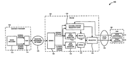
- the architecture 100 includes a content provider 110 , a regional broadband network 120 , a digital subscriber line access multiplexer (DSLAM) 130 , a local loop 140 , and a set top box (STB) 150 .
- the content provider 110 includes a video encoder 112 having a first and a second output in signal communication with a first and second input, respectively, of a multiplexer 114 .
- An output of the multiplexer 114 provides an output of the content provider 110 , which is connected in signal communication with the regional broadband network 120 .
- the regional broadband network 120 is further connected in signal communication with an input of the DSLAM 130 .
- the DSLAM 130 includes a demultiplexer 132 having a first output in signal communication with an input of an I-picture detector 133 and a second output in signal communication with an input of an I-picture detector 134 .
- An output of the I-picture detector 133 is connected in signal communication with a first input of channel change selection logic 135 and with a first input of a delay device 136 .
- An output of the I-picture detector 134 is connected in signal communication with a second input of the channel change selection logic 135 and with an input of a storage device 137 .
- a first output of the channel change selection logic 135 is connected in signal communication with a second input of the delay device 136 .
- a second output of the channel change selection logic 135 is connected in signal communication with a first input of a selector 138 .
- An output of the delay device is connected in signal communication with a second input of the selector 138 .
- An output of the storage device 137 is connected in signal communication with a third input of the selector 138 .
- a first input of the DSLAM 130 is connected in signal communication with an input of the demultiplexer 132 , a second input of the DSLAM 130 is connected in signal communication with a third input of the selector 138 , and an output of the DSLAM 130 is connected in signal communication with an output of the selector 138 .
- the second input and the output of the DSLAM 130 are connected in signal communication with the local loop 140 .
- the DSLAM 130 is also interchangeably referred to herein as a “channel change processing unit”.
- the STB 150 includes a user interface 152 and a video decoder 154 .
- An output of the STB 150 is connected in signal communication with the local loop 140 and with the user interface 152
- an input of the STB 150 is connected in signal communication with the local loop 140 and with the video decoder 154 .
- the I-picture detectors 133 , 134 are for detecting I-pictures in the normal stream.
- the delay device 136 is for providing a variable delay.
- the video encoder 112 creates both a normal stream and a channel change stream of coded pictures.
- the normal stream and channel change stream are multiplexed 114 together and transmitted over a regional broadband network 120 to the DSLAM 130 .
- a regional broadband network 120 For the sake of simplicity with respect to FIG. 1 , only a single program's encoder is shown. In an actual system, multiple programs are supported and, thus, blocks in the figure are duplicated for each supported program.
- a user makes a channel change request through the user interface 152 in the STB 150 , to indicate a switch to a new program to be viewed. This request is forwarded to the DSLAM 130 .
- the channel change stream is stored in storage local (e.g., local storage device 136 ) to the DSLAM 130 (or remote storage which may be quickly accessed by the DSLAM 130 ).
- the normal stream is transmitted over the local loop 140 to the video decoder 154 at the STB 150 .
- a channel change request is initiated by the user interface of the STB 150 , it is sent to the DSLAM 130 through the local loop 140 .
- the DSLAM 130 Upon receiving the channel change request, the DSLAM 130 begins to send the stored channel change stream of the new program to the STB 150 , beginning with an I-picture in the channel change stream, instead of the normal stream. Then, at a later point, the DSLAM 130 switches back to transmitting the normal stream to the STB 150 .
- Sending the channel change stream in addition to the normal stream increases the bandwidth requirement over the regional broadband network 120 . This increase is bandwidth is sustained until a “leave” request on the channel change stream is initiated by the STB 150 .
- the DSLAM (or upstream processing element instrumenting the channel change request, hereinafter referred to as “DSLAM” 130 ) is cognizant of the paired normal stream and channel change stream available at its input. Moreover, it is further presumed that the DSLAM 130 is capable of detecting when an I-picture is presented on any input stream, e.g., using I-picture detectors 133 , 134 .
- the DSLAM first switches the channel-change stream automatically to the STB 150 at the next available I-picture. The DSLAM then sets a flag to inspect the arrival of the subsequent I-picture on the normal stream.
- the channel change stream has more frequent I-picture while the normal stream has less frequent I-pictures.
- the subsequent I-picture has arrived on the normal stream, it is switched to serve the customer who made the original request.
- the present invention is more bandwidth efficient in the DSL link (local loop 140 ), but does require the DSLAM 130 (or upstream channel change processing element) to keep track of the switch between the channel change and normal stream functions.
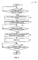
- a begin block 210 passes control to a decision block 220 .
- the decision block 220 determines whether or not a channel change request has been received to play a current program. If the channel change request has not been received, then control passes back to decision block 220 . Otherwise, if the channel change request has been received, then control passes to a function block 222 .
- the function block 222 sends a channel change stream coded I-picture, and passes control to a function block 224 .
- the function block 224 sets a flag to inspect the arrival of a subsequent I-picture on the normal stream, and passes control to a decision block 226 .
- the decision block 226 determines whether or not the subsequent I-picture has arrived on the normal stream. If the subsequent I-picture has not yet arrived on the normal stream, then control is returned to decision block 226 . Otherwise, if the subsequent I-picture has arrived on the normal stream, then control is passed to a function block 240 .
- the function block 240 sends the normal stream (including the subsequent I-picture) to the individual/device requesting the channel change, and passes control to a function block 245 .
- the function block 245 resets the flag, and passes control to a decision block 250 .
- the decision block 250 determines whether or not a channel change request has been received to exit a current program. If the channel change request has not been received, then control passes back to function block 240 . Otherwise, if the channel change request has been received, then control passes to an end block 260 .
- the teachings of the present invention are implemented as a combination of hardware and software.
- the software is preferably implemented as an application program tangibly embodied on a program storage unit.
- the application program may be uploaded to, and executed by, a machine comprising any suitable architecture.
- the machine is implemented on a computer platform having hardware such as one or more central processing units (“CPU”), a random access memory (“RAM”), and input/output (“I/O”) interfaces.
- CPU central processing units
- RAM random access memory
- I/O input/output
- the computer platform may also include an operating system and microinstruction code.
- the various processes and functions described herein may be either part of the microinstruction code or part of the application program, or any combination thereof, which may be executed by a CPU.
- various other peripheral units may be connected to the computer platform such as an additional data storage unit and a printing unit.
Abstract
There are provided a circuit and corresponding method for enabling a channel change in a digital network. The circuit has inputs for receiving a channel change stream and a normal stream. The circuit further includes a multiplexer, a memory device, and a picture element detector. The multiplexer is for transmitting the channel change stream to a customer premises equipment (CPE) device in response to a channel change request from the CPE device. The memory device is for storing a flag that is set in response to the channel change request from the CPE device. The flag is set to request detection of a picture element in the normal stream. The picture element detector is for detecting the picture element in the normal stream subsequent to transmitting the channel change stream. The multiplexer transmits the normal stream to the CPE device in place of the channel change stream once the picture element is detected in the normal stream.
Description
- This application claims the benefit of U.S. Provisional Application Ser. No. 60/633,475, filed Dec. 6, 2004, which is incorporated by reference herein in its entirety.
- The present invention relates generally to digital networks and, more particularly, to a method and apparatus for enabling a channel change in a digital network.
- In a Digital Subscriber Line (DSL) multicast/broadcast video system, Internet Protocol (IP) multicast can be used to transmit compressed video to a set-top box (STB). The Internet Group Management Protocol (IGMP) is a mechanism to select which channel to watch, by sending a join request for the desired channel to a Digital Subscriber Line Access Multiplexer (DSLAM). When that channel is no longer desired, a leave request can be sent to the DSLAM.
- In a commercial video over DSL broadcast system, it is desirable to allow end users to be able to change channels rapidly. Popular video compression standards, such as MPEG-2 and JVT/H.264/MPEG AVC use intra and inter coding. For proper decoding, a decoder must decode a compressed video sequence beginning with an intra-coded (I) picture or instantaneous decoder refresh (IDR) picture or an I-slice, and then continuing to decode the subsequent inter-coded (P and B) pictures. A Group of Pictures (GOP) may include at least one I-picture and at least one P and/or B picture. I-pictures typically require many more bits to code than a P or B picture of equivalent video quality, often in the range of 3-10 times as many bits.
- When a receiver initially begins receiving a program on a particular channel, following a channel change or upon the initial turning on of the receiver, the receiver must wait until an I-picture is received to begin decoding properly, which causes a delay.
- To minimize channel change delay in digital video broadcast systems, I-pictures are typically sent frequently, e.g., every N pictures. For example, to enable a ½ second delay (of the video compression portion of the system), it is common to use N=15 for 30 fps content. Since compressed I-pictures are much larger than compressed P and B pictures, this considerably increases the bitrate over what would be required if I-pictures were not inserted so frequently.
- In a first prior art system, a channel change stream was encoded and transmitted along with the normal video bitstream. The channel change stream included lower quality I-pictures that were sent at a higher frequency than I-pictures in the normal bitstream. When a user tuned to a new channel, playback could begin upon receipt of the first I-pictures, in either the normal or channel change stream.
- In a second prior art system, for each program, a relatively low bitrate, low resolution channel change stream is encoded, in addition to the normal coded stream. When a channel change request is received at the Customer Premises Equipment (CPE), join request are made to both the channel change stream and the normal stream of the newly selected program and both streams are sent down the DSL link. The CPE then appropriately makes the switchover from the channel change stream to the normal stream.
- Since the solution in the second prior art system above calls for both the normal and channel change stream to be sent over the DSL link when a channel change request is made, it will result in increased bandwidth until the CPE initiates a “leave” request on the channel-change stream. For example, a user zapping through HD channels could cause an increased bandwidth usage of a lower resolution (possibly SD resolution) channel.
- Accordingly, it would be desirable and highly advantageous to have a method and apparatus for enabling a channel change in a digital network that overcomes the above-described problems of the prior art.
- These and other drawbacks and disadvantages of the prior art are addressed by the present invention, which is directed to a method and apparatus for enabling a channel change in a digital network.
- According to an aspect of the present invention, there is provided a circuit for enabling a channel change in a digital network. The circuit has inputs for receiving a channel change stream and a normal stream. The circuit further includes a multiplexer, a memory device, and a picture element detector. The multiplexer is for transmitting the channel change stream to a customer premises equipment (CPE) device in response to a channel change request from the CPE device. The memory device is for storing a flag that is set in response to the channel change request from the CPE device. The flag is set to request detection of a picture element in the normal stream. The picture element detector is for detecting the picture element in the normal stream subsequent to transmitting the channel change stream. The multiplexer transmits the normal stream to the CPE device in place of the channel change stream once the picture element is detected in the normal stream.
- According to another aspect of the present invention, there is provided, in a circuit connected to a digital network and having inputs for receiving a channel change stream and a normal stream, a method for enabling a channel change in the digital network. The method includes the step of transmitting the channel change stream to a customer premises equipment (CPE) device in response to a channel change request from the CPE device. The method also includes the step of setting a flag, in response to the channel change request from the CPE device, to request detection of a picture element in the normal stream. The also further includes the step of detecting the picture element in the normal stream subsequent to transmitting the channel change stream. Moreover, the method includes the step of transmitting the normal stream to the CPE device in place of the channel change stream, once the picture element is detected in the normal stream.
- These and other aspects, features and advantages of the present invention will become apparent from the following detailed description of exemplary embodiments, which is to be read in connection with the accompanying drawings.
- The present invention may be better understood in accordance with the following exemplary figures, in which:
-
FIG. 1 shows a block diagram for an end-to-end architecture in accordance with the principles of the present invention; and -
FIG. 2 shows a flow diagram for a method for enabling a channel change in a Digital Subscriber Line (DSL) system in accordance with the principles of the present invention. - The present invention is directed to a method and apparatus for enabling a channel change in a digital network.
- Advantageously, the present invention improves upon the first and second prior art systems described herein above, overcoming the above-described deficiencies associated therewith. For example, the present invention reduces bandwidth consumption for a Customer Premises Equipment (CPE) initiated, low-delay channel-change mechanism over a Digital Subscriber Loop (DSL) system. In accordance with the principles of the present invention, the request for channel change is made by the CPE. The digital subscriber line access multiplexer (DSLAM) (or some other equipment upstream), in response to this request, switches in a lower-resolution channel-change stream and at an appropriate time later, switches in the full-resolution stream.
- It is to be appreciated that the phrases “customer service equipment” (CPE) and “set top box” (STB) are used interchangeably herein. The term “memoryless picture element” refers to a current picture element that does depend on a preceding picture element or a succeeding picture element. Moreover, it is to be further appreciated that the terms “I-picture” and “memoryless picture element” are used interchangeably herein to refer to any of I-slices, instantaneous decoder refresh (IDR) pictures, or I-pictures.
- Moreover, it is to be appreciated that while the present invention is primarily described herein with respect to a specific example of a digital network, namely a digital subscriber line (DSL) network, given the teachings of the present invention provided herein, one of ordinary skill in the related art may readily apply the present invention to any switched digital network while maintaining the scope of the present invention.
- The present description illustrates the principles of the present invention. It will thus be appreciated that those skilled in the art will be able to devise various arrangements that, although not explicitly described or shown herein, embody the principles of the invention and are included within its spirit and scope.
- All examples and conditional language recited herein are intended for pedagogical purposes to aid the reader in understanding the principles of the invention and the concepts contributed by the inventor to furthering the art, and are to be construed as being without limitation to such specifically recited examples and conditions.
- Moreover, all statements herein reciting principles, aspects, and embodiments of the invention, as well as specific examples thereof, are intended to encompass both structural and functional equivalents thereof. Additionally, it is intended that such equivalents include both currently known equivalents as well as equivalents developed in the future, i.e., any elements developed that perform the same function, regardless of structure.
- Thus, for example, it will be appreciated by those skilled in the art that the block diagrams presented herein represent conceptual views of illustrative circuitry embodying the principles of the invention. Similarly, it will be appreciated that any flow charts, flow diagrams, state transition diagrams, pseudocode, and the like represent various processes which may be substantially represented in computer readable media and so executed by a computer or processor, whether or not such computer or processor is explicitly shown.
- The functions of the various elements shown in the figures may be provided through the use of dedicated hardware as well as hardware capable of executing software in association with appropriate software. When provided by a processor, the functions may be provided by a single dedicated processor, by a single shared processor, or by a plurality of individual processors, some of which may be shared. Moreover, explicit use of the term “processor” or “controller” should not be construed to refer exclusively to hardware capable of executing software, and may implicitly include, without limitation, digital signal processor (“DSP”) hardware, read-only memory (“ROM”) for storing software, random access memory (“RAM”), and non-volatile storage.
- Other hardware, conventional and/or custom, may also be included. Similarly, any switches shown in the figures are conceptual only. Their function may be carried out through the operation of program logic, through dedicated logic, through the interaction of program control and dedicated logic, or even manually, the particular technique being selectable by the implementer as more specifically understood from the context.
- In the claims hereof, any element expressed as a means for performing a specified function is intended to encompass any way of performing that function including, for example, a) a combination of circuit elements that performs that function or b) software in any form, including, therefore, firmware, microcode or the like, combined with appropriate circuitry for executing that software to perform the function. The invention as defined by such claims resides in the fact that the functionalities provided by the various recited means are combined and brought together in the manner which the claims call for. It is thus regarded that any means that can provide those functionalities are equivalent to those shown herein.
- Advantageously, as noted above, the present invention provides a method and apparatus for enabling a channel change in a digital network including, but not limited to, a digital subscribe line (DSL) network. The present invention provides an improvement over prior art systems such as the second prior art system described above, by minimizing bandwidth consumption in, e.g., a local loop of a DSL network, as compared to the prior art.
- In prior art systems such the second prior art system described above, both the normal and channel change stream are sent over the DSL link (local loop) when a channel change request is made, thereby resulting in a problem of increased bandwidth until the CPE initiates a “leave” request on the channel-change stream. Advantageously, the present invention solves this problem.
- Turning to
FIG. 1 , an exemplary end-to-end architecture to which the present invention may be applied is indicated generally by thereference numeral 100. Thearchitecture 100 includes acontent provider 110, aregional broadband network 120, a digital subscriber line access multiplexer (DSLAM) 130, alocal loop 140, and a set top box (STB) 150. Thecontent provider 110 includes avideo encoder 112 having a first and a second output in signal communication with a first and second input, respectively, of amultiplexer 114. An output of themultiplexer 114 provides an output of thecontent provider 110, which is connected in signal communication with theregional broadband network 120. Theregional broadband network 120 is further connected in signal communication with an input of theDSLAM 130. - The
DSLAM 130 includes ademultiplexer 132 having a first output in signal communication with an input of an I-picture detector 133 and a second output in signal communication with an input of an I-picture detector 134. An output of the I-picture detector 133 is connected in signal communication with a first input of channelchange selection logic 135 and with a first input of adelay device 136. An output of the I-picture detector 134 is connected in signal communication with a second input of the channelchange selection logic 135 and with an input of astorage device 137. A first output of the channelchange selection logic 135 is connected in signal communication with a second input of thedelay device 136. A second output of the channelchange selection logic 135 is connected in signal communication with a first input of a selector 138. An output of the delay device is connected in signal communication with a second input of the selector 138. An output of thestorage device 137 is connected in signal communication with a third input of the selector 138. - A first input of the
DSLAM 130 is connected in signal communication with an input of thedemultiplexer 132, a second input of theDSLAM 130 is connected in signal communication with a third input of the selector 138, and an output of theDSLAM 130 is connected in signal communication with an output of the selector 138. The second input and the output of theDSLAM 130 are connected in signal communication with thelocal loop 140. It is to be appreciated that theDSLAM 130 is also interchangeably referred to herein as a “channel change processing unit”. - The
STB 150 includes a user interface 152 and a video decoder 154. An output of theSTB 150 is connected in signal communication with thelocal loop 140 and with the user interface 152, and an input of theSTB 150 is connected in signal communication with thelocal loop 140 and with the video decoder 154. - The I-
picture detectors delay device 136 is for providing a variable delay. - The
video encoder 112 creates both a normal stream and a channel change stream of coded pictures. The normal stream and channel change stream are multiplexed 114 together and transmitted over aregional broadband network 120 to theDSLAM 130. For the sake of simplicity with respect toFIG. 1 , only a single program's encoder is shown. In an actual system, multiple programs are supported and, thus, blocks in the figure are duplicated for each supported program. A user makes a channel change request through the user interface 152 in theSTB 150, to indicate a switch to a new program to be viewed. This request is forwarded to theDSLAM 130. - In a preferred embodiment of the present invention, the channel change stream is stored in storage local (e.g., local storage device 136) to the DSLAM 130 (or remote storage which may be quickly accessed by the DSLAM 130). During normal viewing, the normal stream is transmitted over the
local loop 140 to the video decoder 154 at theSTB 150. When a channel change request is initiated by the user interface of theSTB 150, it is sent to theDSLAM 130 through thelocal loop 140. Upon receiving the channel change request, theDSLAM 130 begins to send the stored channel change stream of the new program to theSTB 150, beginning with an I-picture in the channel change stream, instead of the normal stream. Then, at a later point, theDSLAM 130 switches back to transmitting the normal stream to theSTB 150. - Sending the channel change stream in addition to the normal stream increases the bandwidth requirement over the
regional broadband network 120. This increase is bandwidth is sustained until a “leave” request on the channel change stream is initiated by theSTB 150. - For the purposes of the present invention, it is presumed that the DSLAM (or upstream processing element instrumenting the channel change request, hereinafter referred to as “DSLAM” 130) is cognizant of the paired normal stream and channel change stream available at its input. Moreover, it is further presumed that the
DSLAM 130 is capable of detecting when an I-picture is presented on any input stream, e.g., using I-picture detectors STB 150 initiates a channel change request, the DSLAM first switches the channel-change stream automatically to theSTB 150 at the next available I-picture. The DSLAM then sets a flag to inspect the arrival of the subsequent I-picture on the normal stream. As was described in the first and second prior art systems described above, for bandwidth saving reasons, the channel change stream has more frequent I-picture while the normal stream has less frequent I-pictures. When the subsequent I-picture has arrived on the normal stream, it is switched to serve the customer who made the original request. - It is to be appreciated that the present invention is more bandwidth efficient in the DSL link (local loop 140), but does require the DSLAM 130 (or upstream channel change processing element) to keep track of the switch between the channel change and normal stream functions.
- Turning to
FIG. 2 , in a Digital Subscriber Line Access Multiplexer (DSLAM) of a DSL system, a method for enabling a channel change is indicated generally by thereference numeral 200. Abegin block 210 passes control to adecision block 220. Thedecision block 220 determines whether or not a channel change request has been received to play a current program. If the channel change request has not been received, then control passes back todecision block 220. Otherwise, if the channel change request has been received, then control passes to afunction block 222. Thefunction block 222 sends a channel change stream coded I-picture, and passes control to afunction block 224. Thefunction block 224 sets a flag to inspect the arrival of a subsequent I-picture on the normal stream, and passes control to adecision block 226. Thedecision block 226 determines whether or not the subsequent I-picture has arrived on the normal stream. If the subsequent I-picture has not yet arrived on the normal stream, then control is returned todecision block 226. Otherwise, if the subsequent I-picture has arrived on the normal stream, then control is passed to afunction block 240. - The
function block 240 sends the normal stream (including the subsequent I-picture) to the individual/device requesting the channel change, and passes control to afunction block 245. Thefunction block 245 resets the flag, and passes control to adecision block 250. Thedecision block 250 determines whether or not a channel change request has been received to exit a current program. If the channel change request has not been received, then control passes back tofunction block 240. Otherwise, if the channel change request has been received, then control passes to an end block 260. - These and other features and advantages of the present invention may be readily ascertained by one of ordinary skill in the pertinent art based on the teachings herein. It is to be understood that the teachings of the present invention may be implemented in various forms of hardware, software, firmware, special purpose processors, or combinations thereof.
- Most preferably, the teachings of the present invention are implemented as a combination of hardware and software. Moreover, the software is preferably implemented as an application program tangibly embodied on a program storage unit. The application program may be uploaded to, and executed by, a machine comprising any suitable architecture. Preferably, the machine is implemented on a computer platform having hardware such as one or more central processing units (“CPU”), a random access memory (“RAM”), and input/output (“I/O”) interfaces. The computer platform may also include an operating system and microinstruction code. The various processes and functions described herein may be either part of the microinstruction code or part of the application program, or any combination thereof, which may be executed by a CPU. In addition, various other peripheral units may be connected to the computer platform such as an additional data storage unit and a printing unit.
- It is to be further understood that, because some of the constituent system components and methods depicted in the accompanying drawings are preferably implemented in software, the actual connections between the system components or the process function blocks may differ depending upon the manner in which the present invention is programmed. Given the teachings herein, one of ordinary skill in the pertinent art will be able to contemplate these and similar implementations or configurations of the present invention.
- Although the illustrative embodiments have been described herein with reference to the accompanying drawings, it is to be understood that the present invention is not limited to those precise embodiments, and that various changes and modifications may be effected therein by one of ordinary skill in the pertinent art without departing from the scope or spirit of the present invention. All such changes and modifications are intended to be included within the scope of the present invention as set forth in the appended claims.
Claims (16)
1. A circuit for enabling a channel change in a digital network, the circuit having inputs for receiving a channel change stream and a normal stream, the circuit further comprising:
a multiplexer for transmitting the channel change stream to a customer premises equipment (CPE) device in response to a channel change request from the CPE device;
a memory device for storing a flag that is set in response to the channel change request from the CPE device, the flag being set to request detection of a picture element in the normal stream; and
a picture element detector for detecting the picture element in the normal stream subsequent to transmitting the channel change stream,
wherein said multiplexer transmits the normal stream to the CPE device in place of the channel change stream once the picture element is detected in the normal stream.
2. The circuit according to claim 1 , wherein the picture element is a memoryless picture element.
3. The circuit according to claim 1 , wherein the channel change stream includes more picture elements than the normal stream.
4. The circuit according to claim 1 , wherein the flag stored in the memory device is reset, when the picture element is detected in the normal stream.
5. The circuit according to claim 1 , further comprising a variable delay device for delaying the normal stream prior to a transmission of the normal stream from the multiplexer to the CPE device.
6. The circuit according to claim 1 , wherein the circuit is implemented in a digital subscriber line access modem (DLSAM).
7. The circuit according to claim 1 , wherein the digital network is a digital subscriber line (DSL) network.
8. The circuit according to claim 1 , wherein the picture element comprises any of an I-slice, an I-picture, and an instantaneous decoder refresh (IDR) picture.
9. In a circuit connected to a digital network and having inputs for receiving a channel change stream and a normal stream, a method for enabling a channel change in the digital network, the method comprising the steps of:
transmitting the channel change stream to a customer premises equipment (CPE) device in response to a channel change request from the CPE device;
setting a flag, in response to the channel change request from the CPE device, to request detection of a picture element in the normal stream;
detecting the picture element in the normal stream subsequent to transmitting the channel change stream; and
transmitting the normal stream to the CPE device in place of the channel change stream, once the picture element is detected in the normal stream.
10. The method according to claim 9 , wherein said picture element is a memoryless picture element.
11. The method according to claim 9 , wherein the channel change stream includes more picture elements than the normal stream.
12. The method according to claim 9 , further comprising the step of resetting the flag, when the picture element is detected in the normal stream.
13. The method according to claim 9 , further comprising the step of delaying the normal stream prior to a transmission of the normal stream from the circuit to the CPE device.
14. The method according to claim 9 , wherein the circuit is implemented in a digital subscriber line access modem (DLSAM).
15. The method according to claim 9 , wherein the digital network is a digital subscriber line (DSL) network.
16. The method according to claim 9 , wherein the picture element comprises any of an I-slice, an I-picture, and an instantaneous decoder refresh (IDR) picture.
Priority Applications (1)
| Application Number | Priority Date | Filing Date | Title |
|---|---|---|---|
| US11/791,776 US20080098428A1 (en) | 2004-12-06 | 2005-07-15 | Network Managed Channel Change In Digital Networks |
Applications Claiming Priority (3)
| Application Number | Priority Date | Filing Date | Title |
|---|---|---|---|
| US63347304P | 2004-12-06 | 2004-12-06 | |
| PCT/US2005/024936 WO2006062551A1 (en) | 2004-12-06 | 2005-07-15 | Network managed channel change in digital networks |
| US11/791,776 US20080098428A1 (en) | 2004-12-06 | 2005-07-15 | Network Managed Channel Change In Digital Networks |
Publications (1)
| Publication Number | Publication Date |
|---|---|
| US20080098428A1 true US20080098428A1 (en) | 2008-04-24 |
Family
ID=36578221
Family Applications (2)
| Application Number | Title | Priority Date | Filing Date |
|---|---|---|---|
| US11/792,009 Expired - Fee Related US8135041B2 (en) | 2004-12-06 | 2005-07-14 | Multiple closed captioning flows and customer access in digital networks |
| US11/791,776 Abandoned US20080098428A1 (en) | 2004-12-06 | 2005-07-15 | Network Managed Channel Change In Digital Networks |
Family Applications Before (1)
| Application Number | Title | Priority Date | Filing Date |
|---|---|---|---|
| US11/792,009 Expired - Fee Related US8135041B2 (en) | 2004-12-06 | 2005-07-14 | Multiple closed captioning flows and customer access in digital networks |
Country Status (6)
| Country | Link |
|---|---|
| US (2) | US8135041B2 (en) |
| EP (1) | EP1820336A4 (en) |
| JP (1) | JP4901751B2 (en) |
| KR (1) | KR101200928B1 (en) |
| CN (1) | CN101091382B (en) |
| WO (1) | WO2006062553A1 (en) |
Cited By (1)
| Publication number | Priority date | Publication date | Assignee | Title |
|---|---|---|---|---|
| US20080037441A1 (en) * | 2006-07-21 | 2008-02-14 | Deepak Kataria | Methods and Apparatus for Prevention of Excessive Control Message Traffic in a Digital Networking System |
Families Citing this family (21)
| Publication number | Priority date | Publication date | Assignee | Title |
|---|---|---|---|---|
| US7519274B2 (en) | 2003-12-08 | 2009-04-14 | Divx, Inc. | File format for multiple track digital data |
| US8472792B2 (en) | 2003-12-08 | 2013-06-25 | Divx, Llc | Multimedia distribution system |
| WO2007106844A2 (en) | 2006-03-14 | 2007-09-20 | Divx, Inc. | Federated digital rights management scheme including trusted systems |
| EP2122482B1 (en) | 2007-01-05 | 2018-11-14 | Sonic IP, Inc. | Video distribution system including progressive playback |
| US7954123B2 (en) * | 2007-09-26 | 2011-05-31 | Alcatel Lucent | System, method, and computer-readable medium for synchronizing multicast customized content to facilitate DSLAM complexity reduction |
| WO2009065137A1 (en) | 2007-11-16 | 2009-05-22 | Divx, Inc. | Hierarchical and reduced index structures for multimedia files |
| JP2012513689A (en) * | 2008-07-25 | 2012-06-14 | ノーテル ネットワークス リミテッド | Multi-segment loss protection |
| US8330864B2 (en) * | 2008-11-02 | 2012-12-11 | Xorbit, Inc. | Multi-lingual transmission and delay of closed caption content through a delivery system |
| CN102065235B (en) * | 2009-11-12 | 2015-06-24 | 新奥特(北京)视频技术有限公司 | Method and device for generating universal subtitle |
| CN102065234B (en) * | 2009-11-12 | 2014-11-05 | 新奥特(北京)视频技术有限公司 | Caption producing and broadcasting method and system based on distributive type caption processing system |
| CN102065236B (en) * | 2009-11-12 | 2015-03-25 | 新奥特(北京)视频技术有限公司 | Fabricating method and device for subtitle file |
| EP2507995A4 (en) | 2009-12-04 | 2014-07-09 | Sonic Ip Inc | Elementary bitstream cryptographic material transport systems and methods |
| US8914534B2 (en) | 2011-01-05 | 2014-12-16 | Sonic Ip, Inc. | Systems and methods for adaptive bitrate streaming of media stored in matroska container files using hypertext transfer protocol |
| US9467708B2 (en) | 2011-08-30 | 2016-10-11 | Sonic Ip, Inc. | Selection of resolutions for seamless resolution switching of multimedia content |
| US8787570B2 (en) | 2011-08-31 | 2014-07-22 | Sonic Ip, Inc. | Systems and methods for automatically genenrating top level index files |
| US8909922B2 (en) | 2011-09-01 | 2014-12-09 | Sonic Ip, Inc. | Systems and methods for playing back alternative streams of protected content protected using common cryptographic information |
| CN104204203A (en) * | 2012-03-22 | 2014-12-10 | 和光纯药工业株式会社 | Method for detecting DNA having microsatellite region |
| US9191457B2 (en) | 2012-12-31 | 2015-11-17 | Sonic Ip, Inc. | Systems, methods, and media for controlling delivery of content |
| US10244203B1 (en) * | 2013-03-15 | 2019-03-26 | Amazon Technologies, Inc. | Adaptable captioning in a video broadcast |
| US10345289B2 (en) * | 2013-04-18 | 2019-07-09 | The Board Of Trustees Of The University Of Illinois | Method and apparatus for analyzing a target material |
| KR102012682B1 (en) | 2015-01-06 | 2019-08-22 | 디브이엑스, 엘엘씨 | Systems and Methods for Encoding and Sharing Content Between Devices |
Citations (26)
| Publication number | Priority date | Publication date | Assignee | Title |
|---|---|---|---|---|
| US4625081A (en) * | 1982-11-30 | 1986-11-25 | Lotito Lawrence A | Automated telephone voice service system |
| US5187733A (en) * | 1991-12-20 | 1993-02-16 | At&T Bell Laboratories | Verification of subscriber lines prior to cutover to a new switching system |
| US5719864A (en) * | 1995-08-11 | 1998-02-17 | International Business Machines Corp. | Logical channel resolution in asynchronous transmission mode communication systems |
| US5732217A (en) * | 1995-12-01 | 1998-03-24 | Matsushita Electric Industrial Co., Ltd. | Video-on-demand system capable of performing a high-speed playback at a correct speed |
| US6081517A (en) * | 1997-09-22 | 2000-06-27 | Integrated Telecom Express, Inc. | Digital subscriber loop access circuit for digital switch and packet network interconnections |
| US6246695B1 (en) * | 1995-06-21 | 2001-06-12 | Bell Atlantic Network Services, Inc. | Variable rate and variable mode transmission system |
| US20020073427A1 (en) * | 1998-12-22 | 2002-06-13 | Hugh Boyd Morrison | Providing a link to programs in a program guide |
| US20020114331A1 (en) * | 2000-12-13 | 2002-08-22 | Cheung Kwok Wai | Method and system for delivering media selections through a network |
| US6456839B1 (en) * | 1998-12-30 | 2002-09-24 | At&T Corp. | Method and apparatus for billing a neighborhood cordless service |
| US6473427B1 (en) * | 1999-06-24 | 2002-10-29 | Qwest Communications | ATM based VDSL communication system having meta signaling for switching a subscriber between different data service providers |
| US6587476B1 (en) * | 1999-05-26 | 2003-07-01 | 3 Com Corporation | Ethernet frame encapsulation over VDSL using HDLC |
| US6678740B1 (en) * | 2000-01-14 | 2004-01-13 | Terayon Communication Systems, Inc. | Process carried out by a gateway in a home network to receive video-on-demand and other requested programs and services |
| US20040034864A1 (en) * | 2002-08-13 | 2004-02-19 | Barrett Peter T. | Seamless digital channel changing |
| US20040033863A1 (en) * | 2002-08-15 | 2004-02-19 | Alan Carlson | Exercising machine for working muscles that support the spine |
| US6728965B1 (en) * | 1997-08-20 | 2004-04-27 | Next Level Communications, Inc. | Channel changer for use in a switched digital video system |
| US6745392B1 (en) * | 1998-09-08 | 2004-06-01 | Symphony Media Systems, Llc | Enhanced security communication system |
| US20040181813A1 (en) * | 2003-02-13 | 2004-09-16 | Takaaki Ota | Methods and systems for rapid channel change within a digital system |
| US20040194134A1 (en) * | 2003-03-25 | 2004-09-30 | Gunatilake Priyan Deveka | Method and system for rapid channel change providing stored images of current channel programs |
| US6804267B1 (en) * | 1997-10-25 | 2004-10-12 | Centillium Communications, Inc. | Transceiver training for DSL modems under TCM-ISDN interference |
| US20050053086A1 (en) * | 2002-03-05 | 2005-03-10 | Nokia Corporation | Method and system for authenticated fast channel change of media provided over a DSL connection |
| US20050081244A1 (en) * | 2003-10-10 | 2005-04-14 | Barrett Peter T. | Fast channel change |
| US20050229221A1 (en) * | 2004-04-05 | 2005-10-13 | Sharp Laboratories Of America Inc. | System and method for low-delay channel hopping |
| US20060020995A1 (en) * | 2004-07-20 | 2006-01-26 | Comcast Cable Communications, Llc | Fast channel change in digital media systems |
| US7206352B2 (en) * | 2001-04-02 | 2007-04-17 | Koninklijke Philips Electronics N.V. | ATSC digital television system |
| US20070107026A1 (en) * | 2005-02-23 | 2007-05-10 | Sherer W P | Fast channel change with conditional return to multicasting |
| US7477653B2 (en) * | 2004-12-10 | 2009-01-13 | Microsoft Corporation | Accelerated channel change in rate-limited environments |
Family Cites Families (22)
| Publication number | Priority date | Publication date | Assignee | Title |
|---|---|---|---|---|
| US5400401A (en) * | 1992-10-30 | 1995-03-21 | Scientific Atlanta, Inc. | System and method for transmitting a plurality of digital services |
| JP3256619B2 (en) * | 1993-12-24 | 2002-02-12 | 株式会社東芝 | Character information display |
| JPH07222072A (en) * | 1994-02-07 | 1995-08-18 | Toshiba Corp | Video image display device |
| US6321383B1 (en) * | 1995-07-31 | 2001-11-20 | Brother Kogyo Kabushiki Kaisha | Information supplying device that can store multiple types of information and supplies composite information in response to a request |
| JP3824332B2 (en) * | 1995-07-31 | 2006-09-20 | 株式会社エクシング | Video information supply system |
| JPH1013809A (en) * | 1996-06-19 | 1998-01-16 | Matsushita Electric Ind Co Ltd | Vod system and vod terminal equipment |
| US6088064A (en) * | 1996-12-19 | 2000-07-11 | Thomson Licensing S.A. | Method and apparatus for positioning auxiliary information proximate an auxiliary image in a multi-image display |
| US6412011B1 (en) * | 1998-09-14 | 2002-06-25 | At&T Corp. | Method and apparatus to enhance a multicast information stream in a communication network |
| US6388700B1 (en) * | 1999-07-19 | 2002-05-14 | Thomson Licensing S.A. | Video processing apparatus and method |
| US6901207B1 (en) * | 2000-03-30 | 2005-05-31 | Lsi Logic Corporation | Audio/visual device for capturing, searching and/or displaying audio/visual material |
| US20020083464A1 (en) * | 2000-11-07 | 2002-06-27 | Mai-Ian Tomsen | System and method for unprompted, context-sensitive querying during a televison broadcast |
| US7676822B2 (en) * | 2001-01-11 | 2010-03-09 | Thomson Licensing | Automatic on-screen display of auxiliary information |
| EP1265439B1 (en) * | 2001-06-06 | 2009-07-08 | Thomson Licensing | Video signal processing system with auxiliary information processing capability |
| AU2002250431A1 (en) | 2001-06-14 | 2003-01-02 | Digeo, Inc. | Method of substituting content during program breaks |
| US20030093814A1 (en) * | 2001-11-09 | 2003-05-15 | Birmingham Blair B.A. | System and method for generating user-specific television content based on closed captioning content |
| US8046792B2 (en) * | 2002-03-20 | 2011-10-25 | Tvworks, Llc | Multi-channel audio enhancement for television |
| KR20040098020A (en) * | 2002-03-21 | 2004-11-18 | 코닌클리케 필립스 일렉트로닉스 엔.브이. | Multi-lingual closed-captioning |
| US8006268B2 (en) * | 2002-05-21 | 2011-08-23 | Microsoft Corporation | Interest messaging entertainment system |
| US20050132420A1 (en) * | 2003-12-11 | 2005-06-16 | Quadrock Communications, Inc | System and method for interaction with television content |
| US8607270B2 (en) * | 2004-02-03 | 2013-12-10 | Microsoft Corporation | Virtual tuner |
| US7630328B2 (en) * | 2004-08-18 | 2009-12-08 | At&T Intellectual Property, I,L.P. | SIP-based session control |
| FR2896145B1 (en) | 2006-01-13 | 2009-02-06 | Spineart Sa Sa | PEDICULAR PLATE AND SCREW SYSTEM AND APPLICATIONS |
-
2005
- 2005-07-14 KR KR1020077012440A patent/KR101200928B1/en active IP Right Grant
- 2005-07-14 WO PCT/US2005/025035 patent/WO2006062553A1/en active Application Filing
- 2005-07-14 EP EP05772185A patent/EP1820336A4/en not_active Withdrawn
- 2005-07-14 JP JP2007544331A patent/JP4901751B2/en not_active Expired - Fee Related
- 2005-07-14 CN CN2005800419141A patent/CN101091382B/en not_active Expired - Fee Related
- 2005-07-14 US US11/792,009 patent/US8135041B2/en not_active Expired - Fee Related
- 2005-07-15 US US11/791,776 patent/US20080098428A1/en not_active Abandoned
Patent Citations (26)
| Publication number | Priority date | Publication date | Assignee | Title |
|---|---|---|---|---|
| US4625081A (en) * | 1982-11-30 | 1986-11-25 | Lotito Lawrence A | Automated telephone voice service system |
| US5187733A (en) * | 1991-12-20 | 1993-02-16 | At&T Bell Laboratories | Verification of subscriber lines prior to cutover to a new switching system |
| US6246695B1 (en) * | 1995-06-21 | 2001-06-12 | Bell Atlantic Network Services, Inc. | Variable rate and variable mode transmission system |
| US5719864A (en) * | 1995-08-11 | 1998-02-17 | International Business Machines Corp. | Logical channel resolution in asynchronous transmission mode communication systems |
| US5732217A (en) * | 1995-12-01 | 1998-03-24 | Matsushita Electric Industrial Co., Ltd. | Video-on-demand system capable of performing a high-speed playback at a correct speed |
| US6728965B1 (en) * | 1997-08-20 | 2004-04-27 | Next Level Communications, Inc. | Channel changer for use in a switched digital video system |
| US6081517A (en) * | 1997-09-22 | 2000-06-27 | Integrated Telecom Express, Inc. | Digital subscriber loop access circuit for digital switch and packet network interconnections |
| US6804267B1 (en) * | 1997-10-25 | 2004-10-12 | Centillium Communications, Inc. | Transceiver training for DSL modems under TCM-ISDN interference |
| US6745392B1 (en) * | 1998-09-08 | 2004-06-01 | Symphony Media Systems, Llc | Enhanced security communication system |
| US20020073427A1 (en) * | 1998-12-22 | 2002-06-13 | Hugh Boyd Morrison | Providing a link to programs in a program guide |
| US6456839B1 (en) * | 1998-12-30 | 2002-09-24 | At&T Corp. | Method and apparatus for billing a neighborhood cordless service |
| US6587476B1 (en) * | 1999-05-26 | 2003-07-01 | 3 Com Corporation | Ethernet frame encapsulation over VDSL using HDLC |
| US6473427B1 (en) * | 1999-06-24 | 2002-10-29 | Qwest Communications | ATM based VDSL communication system having meta signaling for switching a subscriber between different data service providers |
| US6678740B1 (en) * | 2000-01-14 | 2004-01-13 | Terayon Communication Systems, Inc. | Process carried out by a gateway in a home network to receive video-on-demand and other requested programs and services |
| US20020114331A1 (en) * | 2000-12-13 | 2002-08-22 | Cheung Kwok Wai | Method and system for delivering media selections through a network |
| US7206352B2 (en) * | 2001-04-02 | 2007-04-17 | Koninklijke Philips Electronics N.V. | ATSC digital television system |
| US20050053086A1 (en) * | 2002-03-05 | 2005-03-10 | Nokia Corporation | Method and system for authenticated fast channel change of media provided over a DSL connection |
| US20040034864A1 (en) * | 2002-08-13 | 2004-02-19 | Barrett Peter T. | Seamless digital channel changing |
| US20040033863A1 (en) * | 2002-08-15 | 2004-02-19 | Alan Carlson | Exercising machine for working muscles that support the spine |
| US20040181813A1 (en) * | 2003-02-13 | 2004-09-16 | Takaaki Ota | Methods and systems for rapid channel change within a digital system |
| US20040194134A1 (en) * | 2003-03-25 | 2004-09-30 | Gunatilake Priyan Deveka | Method and system for rapid channel change providing stored images of current channel programs |
| US20050081244A1 (en) * | 2003-10-10 | 2005-04-14 | Barrett Peter T. | Fast channel change |
| US20050229221A1 (en) * | 2004-04-05 | 2005-10-13 | Sharp Laboratories Of America Inc. | System and method for low-delay channel hopping |
| US20060020995A1 (en) * | 2004-07-20 | 2006-01-26 | Comcast Cable Communications, Llc | Fast channel change in digital media systems |
| US7477653B2 (en) * | 2004-12-10 | 2009-01-13 | Microsoft Corporation | Accelerated channel change in rate-limited environments |
| US20070107026A1 (en) * | 2005-02-23 | 2007-05-10 | Sherer W P | Fast channel change with conditional return to multicasting |
Cited By (1)
| Publication number | Priority date | Publication date | Assignee | Title |
|---|---|---|---|---|
| US20080037441A1 (en) * | 2006-07-21 | 2008-02-14 | Deepak Kataria | Methods and Apparatus for Prevention of Excessive Control Message Traffic in a Digital Networking System |
Also Published As
| Publication number | Publication date |
|---|---|
| EP1820336A4 (en) | 2010-04-28 |
| US20080018791A1 (en) | 2008-01-24 |
| KR20070085648A (en) | 2007-08-27 |
| WO2006062553A1 (en) | 2006-06-15 |
| JP4901751B2 (en) | 2012-03-21 |
| CN101091382A (en) | 2007-12-19 |
| CN101091382B (en) | 2012-05-16 |
| KR101200928B1 (en) | 2012-11-14 |
| EP1820336A1 (en) | 2007-08-22 |
| JP2008523661A (en) | 2008-07-03 |
| US8135041B2 (en) | 2012-03-13 |
Similar Documents
| Publication | Publication Date | Title |
|---|---|---|
| US20080098428A1 (en) | Network Managed Channel Change In Digital Networks | |
| EP1815684B1 (en) | Method and apparatus for channel change in dsl system | |
| US9497502B2 (en) | Method and apparatus enabling fast channel change for DSL system | |
| US8539525B2 (en) | Method and apparatus in a media player | |
| JP5281793B2 (en) | Fast channel switching in digital video broadcast systems via DSL using redundant video streams | |
| US8750385B2 (en) | Video data loss recovery using low bit rate stream in an IPTV system | |
| EP2070325B1 (en) | Multimedia management | |
| US20060075428A1 (en) | Minimizing channel change time for IP video | |
| US20070266398A1 (en) | Method for fast zapping between tv channels | |
| US20110109808A1 (en) | Method and apparatus for fast channel change using a secondary channel video stream | |
| US20110109810A1 (en) | Method an apparatus for fast channel change using a scalable video coding (svc) stream | |
| US20070171942A1 (en) | System and method for conducting fast channel change for IPTV | |
| JP4823232B2 (en) | Network management channel change in digital networks | |
| KR100994053B1 (en) | System and Tuning Method for Internet Protocol TV Broadcasting Service, IPTV Set-Top Box |
Legal Events
| Date | Code | Title | Description |
|---|---|---|---|
| AS | Assignment |
Owner name: THOMSON LICENSING, FRANCE Free format text: ASSIGNMENT OF ASSIGNORS INTEREST;ASSIGNOR:RAMASWAMY, KUMAR;REEL/FRAME:019396/0699 Effective date: 20050920 |
|
| STCB | Information on status: application discontinuation |
Free format text: ABANDONED -- FAILURE TO RESPOND TO AN OFFICE ACTION |