US20080098703A1 - Hybrid Electric Lawnmower - Google Patents
Hybrid Electric Lawnmower Download PDFInfo
- Publication number
- US20080098703A1 US20080098703A1 US11/670,932 US67093207A US2008098703A1 US 20080098703 A1 US20080098703 A1 US 20080098703A1 US 67093207 A US67093207 A US 67093207A US 2008098703 A1 US2008098703 A1 US 2008098703A1
- Authority
- US
- United States
- Prior art keywords
- power
- motor
- mower
- blade
- hybrid
- Prior art date
- Legal status (The legal status is an assumption and is not a legal conclusion. Google has not performed a legal analysis and makes no representation as to the accuracy of the status listed.)
- Granted
Links
Images


Classifications
-
- A—HUMAN NECESSITIES
- A01—AGRICULTURE; FORESTRY; ANIMAL HUSBANDRY; HUNTING; TRAPPING; FISHING
- A01D—HARVESTING; MOWING
- A01D69/00—Driving mechanisms or parts thereof for harvesters or mowers
- A01D69/02—Driving mechanisms or parts thereof for harvesters or mowers electric
- A01D69/025—Electric hybrid systems
Definitions
- the present invention is related to an electric lawnmower and more particularly to an electric lawnmower having a boost/conserve power feature, a dual mode power supplying providing power to a lawn mower motor as well as dual electric motors powering the cutting blades.
- FIG. 1 is a perspective view of the hybrid mower with power boost conserve features of the present invention
- FIG. 2 is an exploded view of the hybrid mower of FIG. 1 ;
- FIG. 3 is a close up view of the controls for the hybrid mower of FIG. 1 ;
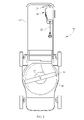
- FIG. 4 is a close up view of the controls for the hybrid mower of FIG. 1 with the interlock handle switch activated;
- FIG. 5 is a bottom view of the hybrid mower of the present invention depicted in FIG. 1 in combination with the AC power input plug;
- FIG. 6 is a circuit diagram of one option of a power control circuit for use with the hybrid mower with boost conserve feature of FIG. 1 ;
- FIG. 7 is a circuit diagram of one option of the power inverter and hybrid control depicted in FIG. 6 for the lawnmower depicted in FIG. 1 ;
- FIG. 8 is one option of the power control circuit for use with the hybrid mower with boost conserve feature depicted in FIG. 1 ;
- FIG. 9 is one option of the power control circuit for use with the hybrid mower with boost conserve feature for the lawnmower depicted in FIG. 1 ;
- FIG. 10 is one option of the power control circuit for use with the hybrid mower with boost conserve feature as depicted in FIG. 1 ;
- FIG. 11 is a bottom view of an alternative mower design having dual blade construction
- FIG. 12 is a schematic of one option of the power control circuit and motor design for one embodiment of a dual motor electric mower
- FIG. 13 is a schematic of one option of the power control circuit and motor design for one embodiment of a dual motor electric mower.
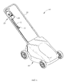
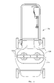
- a hybrid electric lawnmower is described herein and set forth in the claims and is partially depicted in the perspective view of FIG. 1 wherein the hybrid mower 10 is shown having a deck 50 with an outwardly extending handle 55 . Positioned on the outwardly extending handle 55 is a plurality of controls 20 , the controls 20 incorporating a control box 24 , an AC plug 22 and an AC receptacle 23 . Additionally, contained within the deck 50 are a number of features including, but not limited to, the power control and supply described herein as well as a DC motor, a blade, and other necessary features for making the electric lawnmower described herein operable to function as desired.
- Such function and structure include the DC motor to drive the blade, the DC motor powered by alternative power supplies which include 120VAC line voltage or DC power supply such as a batter pack.
- the motor drives the blade and the power supply system of the hybrid electric mower allows the user to select the power source whether it be AC power supply or DC power supply. In either selection, the power control system of the electric mower provides adequate voltage to the motor. Further, a selection is available for the user of the present embodiment to drive the motor in either conserve or boost mode, conserve mode utilizing less power from the power source as boost mode thereby increasing charge time for each full battery charge under such selection, should the DC operation mode be selected, although both conserve and boost mode may be operable in AC operating mode also.
- Further design enhancements may include the addition of a second electric motor in order to increase the cutting width of the electric lawn mower without increasing the blade diameter.
- Increasing blade diameter is problematic in that the total amount of air resistance with longer blades increases substantially the power drain on the battery due to substantial air movement resistance.
- the hybrid mower with a boost conserve feature of the present embodiment is depicted in FIG. 1 with the deck 50 on a plurality of wheels such that the hybrid mower 10 may roll, be powered or be pushed over terrain required to be cut by the blade 51 .
- the specific configuration of the hybrid mower 10 of the present embodiment, as depicted in FIG. 1 is not necessarily limiting in that the many structures and switches which are depicted may be positioned on multiple surfaces or in multiple positions on the hybrid mower 10 and thus, the particular location and limitation of the depictions and structure set forth are considered to be merely exemplary.
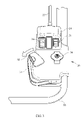
- the hybrid mower 10 of the present embodiment incorporates controls near the handle 55 such that they may be readily accessible to the operator of the mower 10 .
- These handles and controls include a power selection switch 21 , a boost and conserve switch 26 , both of which may be located on the control box 24 .
- Integrated within the control box 24 may also be a circuit breaker 28 , a clutch release 32 and a blade clutch handle 31 , the blade clutch handle 31 acting as an interlock handle switch to engage and disengage the DC motor 56 from rotating the blade 51 .
- the controls 20 on the control box 24 is also shown with the controls 20 on the control box 24 which is the AC power line 22 which may be directly plugged into AC line voltage which is typically 60 Hz 120 Volts.
- the AC power line 22 has a plug receptacle 23 for directly connecting to an extension cord or other device in order to provide AC electrical power to the hybrid mower 10 of the present embodiment.
- the hybrid mower 10 of the present embodiment is designed to be operated on either AC line voltage from an AC power source such as a wall plug or other AC source, or from a DC battery pack which is mounted on the deck 50 or in close conductive and operative relationship with the DC motor 56 depicted.
- the hybrid mower 10 of the present embodiment is so designed that the operator may operatively select functionality of the hybrid mower 10 and the motor 56 by either AC or DC power, the DC alternative coming from the battery pack 52 which may be rechargeable.
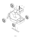
- the rechargeable battery pack 52 is mounted, as depicted in FIG. 2 , on the deck 50 .
- the hybrid mower with boost and conserve feature 10 of the present embodiment includes an option a boost conserve switch 26 which provides the functionality of increasing or decreasing the voltage provided to the DC motor 56 thereby increasing or decreasing the rotational speed of the blade 51 based upon the setting of the boost conserve switch 26 .
- the boost conserve switch 26 may increase or decrease the voltage and thereby increase or decrease the actual drain on the battery pack 52 or other power supply due to the increased current provided to the DC motor 56 .
- the battery pack 52 may be brought in electrical conductivity with the DC motor 56 and the boost and conserve switch 26 may be placed in a conserve switch setting so as to reduce the rotational speed of the blade 51 thereby decreasing the rate of drain of the battery pack 52 and also increasing the run and operation time of the hybrid mower 10 of the present embodiment per charge.
- the DC motor running based upon AC line voltage may use less current while running at such user selection.
- the boost and conserve feature as shown and depicted in the examples and as is effectuated in the present embodiment through the use of the boost conserve toggle switch 26 of FIG. 3 may be integrated with either power selection of the AC power input line or DC power input line to the DC motor 52 . Further descriptions and implementations of such examples will be described hereinafter.
- the controls 20 of the hybrid mower 10 of the present embodiment is depicted with a blade clutch handle 31 and a clutch release 32 such that the blade clutch handle 31 must be operatively held in close relationship to the handle 55 as is commonly understood and known by those of skill in the art in order to engage the DC motor 56 and correspondingly the blade 51 .
- the blade clutch handle 51 when placed and held in close relationship to the handle 55 of FIG. 3 , engages an interlock handle switch as will be described herein which may be a double throw switch, and which operates to act as a user's dead man switch in order to disengage the DC motor if released.
- the interlock handle switch as depicted herein is integrated with the blade clutch handle 31 and acts to operatively disengage the DC motor and also cause resistive breaking of the motor and thus the blade upon release of the handle 31 .
- the present embodiment is directed towards a hybrid electric lawnmower which has a boost and conserve feature.
- Electric lawnmowers, and particularly battery powered mowers have historically had limited mowing time per charge and have had increased weight due to the battery pack.
- prior alternatives had been a corded electric mower with the corresponding restriction of managing a cord and limited power from the household current.
- it has been difficult to mow larger lawns due to the limited mowing time per charge and possibly due to greater height of the lawn which would correspondingly reduce the charge and run time for the battery pack.
- the hybrid control system depicted allows for the hybrid mower 10 to be powered from regular household AC line voltage or from a DC voltage battery pack.
- the battery pack may be designed to have a lower operating voltage available which may be lower than the average peak voltage of the household current. This arrangement may be provided in order to allow the mower to run in a possible conservation mode in order to preserve battery run time under less demanding grass conditions.
- the hybrid mower 10 of the present embodiment may selectively be operated in a boost or power mode, the boost mode allowing the mulching of taller grass or pick up various debris or pine cones from the yard during operation.
- the hybrid mower 10 of the present embodiment may be used without the battery pack so as to be more easily maneuverable in sloped areas due to the reduced weight of not having the battery pack 52 installed. It may also be easier to stow the mower and charge the battery pack 52 separately or alternatively charging the battery when the mower 10 is still in operation.
- the DC motor 56 depicted in FIG. 2 , may be a permanent magnet type DC motor and may be designed to receive power from the battery and/or from the hybrid power controller which will be described herein.
- the DC motor 56 may be provided to power the rotating blade 51 while cutting vegetation and the motor 56 may act as a generator in order to provide resistive breaking after deactivation of the inter-lock handle switch described thereby providing a resistive load to stop the blade quickly once the blade interlock handle 31 is released.
- the motor 56 shown in FIG. 2 may be designed to further provide a fan to promote cooling of the DC motor 56 thereby providing air circulation across the brushes and through the motor.
- Alternative embodiments with multiple motors or with multiple commutators selectively operating in series or in parallel may also be provided.
- the blade 51 may be provided in order to mulch or cut vegetation.
- Typical blade tip speeds of about 16,000 to 19,000 ft. per minute non-cutting with a blade tip speed during cutting of vegetation of between 12,000 to 18,000 ft. per minute with a proportionate horsepower rating for the DC motor of about 1.5. Higher speeds may be indicated when operating from AC line voltage while lower speeds may be recognized operating off of Battery DC voltage.
- the run time can be considerably longer with a battery life expected to be increased by 50% and wherein the speed of the DC motor 56 correspondingly decreases to drive the blade 51 at approximately 14,000 ft. per minute blade speed as measured at the tip of the blade.
- the various speeds of the blade 51 can correspond to a plurality of voltage outputs from the hybrid power supply as seen by the DC motor 56 .
- a voltage of sixty-six or seventy-two volts DC may be presented to the DC motor with a 300 watt/hr batter charge capacity.
- the power consumption may be significantly reduced by providing 60 volts or less to the DC motor 56 .
- boost and conserve selection switch 26 which, as can be seen from the examples depicted herein, may be a single pole double throw switch as shown in order to increase the voltage through the various means depicted and described in the multiple examples hereof
- the corresponding blade speed may be less than 15,000 ft. per minute blade tip measurement and preferably at 14,000 ft. per minute blade tip measurement or less thereby significantly increasing the battery pack charge run time should the battery pack be in operation and the power selection switch 21 be selected in DC mode as depicted in FIG. 3 .
- the 60 volts may be provided to the DC motor which, as depicted in the embodiment of FIG. 2 , the battery pack 52 may be provided with a series of five batteries connected in series, each of the batteries providing 12 volts.
- boost/conserve switch 26 be operated in the boost mode while the power switch 21 is in the DC mode
- additional or secondary battery which may be integrated with or separated from the battery pack 52 depicted in the exemplary drawing, may be brought in series with the battery pack 52 power supply thereby increasing the voltage to 66 or 72 volts, depending on the ultimate desirability and blade speed to be operated.
- variations may be provided in the configuration and implementation while running in DC mode for the battery pack depicted herein as this example is provided merely for descriptive purposes only and many other embodiments including bringing batteries in parallel, series, or providing additional power sources may be utilized.
- One other aspect of the present embodiment of the hybrid mower 10 of the present embodiment is the ability to provide a user selectable power supply to a DC motor driving the blade 51 .
- a DC motor 56 is provided to rotate blade 51 on the mower deck 50 due to its energy use and supply characteristics.
- a user selectable alternative power supply or power selection switch 21 is provided in order that the DC motor 56 may be user switchable from power sources, namely from an AC 120 volt 60 Hz power input representing line voltage should an extension cord or line voltage be readily accessible or alternatively, to a battery pack DC voltage provided on board of the mower, both power supplies selectable by the operator and both power supplies driving the same motor mounted on the lawnmower housing or deck 50 .
- the power control circuit 60 could include a solid state relay which, as an example, has a zero crossing circuit for voltage detection to activate a triac or other relay device to automatically connect the electric motors to line voltage, when plugged into the power control circuit.
- Such user selectable power selection can thus be automated by a automated voltage or other detection circuit or may be actuated by the switch 21 herein described.
- a power control circuit 60 is depicted providing, among other things, the boost and conserve power features of the present embodiment.
- the DC electric motor 56 is shown in electrical connectivity with the various power control circuit elements 60 , 100 which include the inter-lock handle switch 31 , for example being a double pole double throw switch, a circuit breaker 28 being, as depicted herein, a 35 amp breaker, a boost/conserve switch 26 , in this example being a single pole double throw switch, a power selection switch 21 , in this example being a single pole double throw switch, a battery pack 52 which is depicted as a 60 volt DC battery pack providing 60 volts presented to the motor 56 when operatively selected by the power selection switch 21 , and a hybrid AC/DC controller 100 which serves as a power inverter or step down controller for converting the line voltage 120 VAC presented by the plug 23 .
- the inter-lock handle switch 31 for example being a double pole double throw switch
- a circuit breaker 28 being, as depicted herein,
- the battery pack is shown as sharing a common ground with other portions of the power control circuit but may be in electrical connectivity with the power control circuit in many known and understood manners without actual connected electrical wiring as long as the user operation of the lawn mower is actuated through activation of the various switches.
- the boost selection switch 26 provides an increased voltage to the motor 56 by virtue of modifying an input resistive value or timing signal value to the pulse width modulation control unit 120 , which will be described herein, in order to alter the gating of the IGBT thereby affecting the voltage wave form at the output of the power inverter or step down controller 100 .
- the in rush current limiter may be provided as shown in order to prevent oversaturation of the circuit during the initial startup and energizing of the circuit.
- the rectifier 110 as is commonly understood rectifies the voltage from AC to DC, in this case utilizing a full bridge rectifier as shown.
- a full bridge rectifier as shown.
- many different forms of providing a step down controller are known in the art and the depictions set forth are not to be considered unduly limiting.
- the design consists of the AC wall plug 23 which connects to the hybrid AC/DC controller 100 acting as a voltage converter which in turn is connected to a single pole double throw power selection switch 21 and a single pole double throw boost switch 26 .
- the boost switch 26 is the boost conserve switch depicted and described herein and it provides resistive loads to the CMOS micro-controller for the pulse width modulation control 120 depicted when selected and opens the contacts when off.
- the power selection switch 21 toggles the DC motor between the output of the step down controller 100 and the DC battery voltage source 52 .
- the output of the power selection switch 21 feeds a voltage meter shown which may be connected in parallel with the double pole double throw inter-lock handle switch 31 , the inter-lock handle switch 31 toggling between shorting the DC motor 56 through resister R 1 to ground and connecting the output of the power selection switch 21 through a circuit breaker 28 to the DC motor 56 .
- the boost switch 26 may provide increased voltage to the motor 56 when the hybrid mower 10 of the present embodiment is plugged in and running off of line voltage AC power.
- Such boost may be effectuated by modifying the pulse width modulation control 120 through alteration of the input resistive load at input pin 7 of the micro-controller shown in FIG. 7 . More description of the power inverter and/or step down controller 100 of the presently inventive power supply will be set forth herein.
- this embodiment provides an AC wall plug 23 which connects to an AC voltage to the hybrid AC/DC controller 100 which in turn is connected to the power selection switch 21 which allows toggling between output of the AC/DC hybrid controller 100 when in the AC selection and to a boost conserve switch 26 and alternative power source when in the DC position.
- the boost conserve switch 26 toggles between shorting the positive side of the battery source 52 directly to the boost switch 26 went off and connecting the battery source 52 in series with the secondary or boost battery 64 before connecting to the power selection switch or AC/DC switch 21 .
- the power selection switch 21 then feeds a voltage meter V which is connected in parallel with an inter-lock handle switch 31 , here depicted as a double pole double throw switch.
- the inter-lock handle switch 31 toggles between shorting the DC motor 56 through a resistor R 1 to ground and connecting the output of the power selection switch 21 through the circuit breaker 28 to the DC motor 56 .
- additional voltage is provided to the DC motor 56 when the hybrid mower is positioned in the DC power selection option and activation of the boost switch 26 thereby providing an additional 6 volts DC to the 60 volts DC provided by the battery 52 .
- a secondary battery 64 provides additional voltage to the motor thereby increasing the motor speed and corresponding blade speed through actuation of the boost/conserve switch 26 to the boost setting.
- the power control circuit or power supply 160 depicted in FIG. 8 allows the operator while in the DC battery operation mode to increase the operating speed of the motor 56 corresponding to the additional voltage provided by the secondary battery 64 .
- Controls are also provided allowing the operator to select between the operation of the motor 56 through the use of line voltage, namely 120 VAC, or through the use of the battery pack 52 .
- a secondary boost battery 64 which is provided as separate to the battery pack 52 , but it may be more practical to provide a secondary boost battery 64 in combination with and contiguous to the battery pack 52 as assembled and shown in the figures.
- the secondary boost battery 64 may be continuous with the battery pack 52 or may be separate but is provided to add additional voltage to the motor 56 in order to modify the operating output voltage of the power supply as presented to the motor 56 .
- the hybrid AC/DC controller 100 as shown provides both power inverter and step down capabilities in order to modify and regulate the 120 VAC to the proper voltage required to run the DC motor 56 .
- the controller 100 acts as an inverter via rectifier 110 and also to properly modulate the voltage via the PWM controller 120 and associated gates.
- the power inverter and step down controller 100 may be part of the power supply or power control module 60 , 160 , 260 and 360 as needed, or may be excluded, depending on the voltage characteristics of the input line voltage and the requirements of the electric motor implemented in the present design.
- FIG. 9 An alternative construction for the power control is the power supply circuit 260 depicted in FIG. 9 wherein both 120 VAC may be provided to supply power to the motor 56 while optionally a 60 volt DC battery may be provided as operatively selectable by the user through the power selection switch 21 a .
- the boost switch 26 a is operative to bring in series a secondary battery 64 which is 6 volts DC (when set in “BOTH” mode) with the voltage provided by the hybrid controller 100 of the power supply or the battery pack 52 .
- the secondary battery 64 as previously described and as depicted in this embodiment of the power control circuit 260 , may be in combination with the battery pack or secondary and separate thereof.
- the 6 volt battery is brought into the circuit in series with the DC output of the hybrid control 100 or with the battery pack 52 .
- many variations for the structure, assembly and actual value of the secondary battery 64 for all embodiments may be provided in order to increase the voltage to the motor 56 .
- the power selection switch 21 a further provides for three settings allowing user selectable options of powering the DC motor 56 by either 120 VAC, direct battery pack connection or a hybrid BOTH connection.
- the hybrid AC to DC control 100 is depicted regulates and modulates the voltage for proper supplying of voltage to the DC motor 56 .
- the power selection switch 21 a provides for a DC operation whereby the motor 56 is operated merely by the battery pack 52 .
- a third option is placement of the power selection switch 21 a into the BOTH mode wherein there may be a limited amount of power contribution from the battery. In such instance, voltage drops caused by increased load on the motor 56 may result in increased contribution from the battery pack 52 .
- the boost conserve switch 26 a may be provided for contribution of additional voltage from the secondary battery 64 when the power selection switch 21 a is placed in either the BOTH or DC mode. In such an instance, the secondary battery 64 is brought in series with the voltage contribution from either the power supply 100 or the battery pack 52 .
- the power supply circuit 360 consist of a 120 VAC wall plug 23 which connects to the hybrid AC controller 100 which in turn is connected to an exemplary single pole double throw boost switch 26 thereby allowing the circuit to bypass boost battery 64 when off or be connected to the boost battery 64 when on. Additionally, the circuit continues to an exemplary single pole double throw power selection switch 21 which toggles between output of the speed selection switch 26 when in the AC position and the DC battery voltage source 52 when in the DC position.
- the power selection switch 21 feeds a voltage meter V which is connected in parallel with an exemplary double pole double throw inter-lock handle 31 , the inter-lock handle switch 31 toggling between short in the DC motor 56 through a resistor R 1 to ground and connecting the output of the power selection switch 26 through a circuit breaker 66 to the DC motor 56 .
- the boost or secondary battery 64 is brought in parallel with the power pack 52 or with the output of the hybrid controller 100 which may increase the current capacity for the motor when in higher speed or boost mode.
- power control module or power supply may be provided and are described herein.
- hybrid power controller power supply, power control module, step down controller or hybrid controller
- these terms are collectively meant to imply providing electricity to the motor placed on the mower housing.
- No single element set forth in the exemplary embodiments provided herein, namely the power supply elements of the switches, battery packs, circuit breakers, inverters and modulation elements are to be unnecessarily applied to the interpretation of these terms.
- the power supply circuit collectively described herein may be implemented through the use of a significant number of alternative structures for regulation, modulation, controlling or limiting the proper voltage or power to the motor implemented in the examples herein.
- the hybrid controller 100 receives as input 120 volts AC which, in this example, is inverted utilizing a full bridge rectifier 110 depicted in FIG. 7 .
- An in rush current limiter is provided also to prevent current surges during initial loading of the circuit and prevent further damage or over-saturation.
- a number of different inverter designs may be used in order to provide voltage rectification. As depicted in the present example, a full bridge rectifier may be utilized but this may be replaced with other known inverter circuitry as is available and known in the art.
- an optional boost switch may be provided which may correspond to the boost switch 26 depicted in FIG. 6 .
- the boost switch may be operable to modify the input to the pulse width modulation controller 120 which defines the voltage output for the step down controller 100 .
- a micro-controller is utilized in order to set the appropriate pulse rate for the PWM control and feeds into the insulated gate bi-polar transistor (IGBT) which provides the switching or pulse gate driver 122 for the DC output of the hybrid AC/DC control 100 .
- the hybrid controller 100 incorporates, but does not necessarily require, the utilization of voltage rectification and a voltage rectifier as is necessary in combination with variations of voltage modification such as a pulse width modifier.
- step down voltage and control multiple options for step down voltage and control are known and may be utilized such as diode controls, triac controls, MOSFET controls and the like. Many of these are well known in the art and may be utilized in the step down controller and power inverter in combination as described herein.
- the pulse width modulation control circuit 120 receives as input in one possible embodiment the ability to modify the voltage by use of the boost switch.
- the boost switch in this embodiment modifies the reference signal fed into pin 7 of the micro-controller for the reference value which operates to modify the gating of the IGBT and therefore, the voltage characteristics of the DC output depicted.
- the boost mode depicted provides the alternative function of a boost integrated with the power inverter and step down controller. As shown integrated with the controller 100 in FIG. 6 , the boost switch can be alternatively provided in many connections and this integrated boost switch may be integrated with many of the other alternative embodiments.
- the power control module of the present embodiment may utilize power input of 120 VAC and which incorporates many switches and controls for electrically connecting the DC motor to either the 60 volt DC battery or the DC output of the hybrid power controller.
- This may include utilization of a power source switch as indicated wherein the power source switch effectively has a first power input as a connection of the power control module of the DC output of the power inverter and step down controller 100 or receive as a second input the 60 volt DC of the battery pack, the power selection switch providing the ability of the operator to switch between 120 VAC power and 60 VDC power from the battery pack.
- the power selection switch may be directly connected to the DC motor, in this exemplary embodiment a 60 volt DC motor which operates the blade.
- the 60 volt DC motor may be operationally modified by utilization of a boost switch which is optional in many embodiments depicted herein, the boost switch changing voltage applied to the DC motor from 60 volts by an incremental value thereby increasing rotational speed of the blade as necessary by the operator.
- boost switch which is optional in many embodiments depicted herein, the boost switch changing voltage applied to the DC motor from 60 volts by an incremental value thereby increasing rotational speed of the blade as necessary by the operator.
- Such increase in blade speed may be necessitated by thicker grass or due to other items necessarily being mulched by the hybrid mower 10 of the present embodiment.
- This boost/conserve function which is shown herein provides the ability through the many embodiments disclosed to increase the voltage of the power control module and thereby increases the rotational speed of the blades.
- this may be desirable for short periods of time and may provide a first power output of the power control module, the first power output higher than a second power output, the second power output being a conserve feature wherein the DC motor draws less current and thereby increases the battery life charge of the battery pack.
- the increase rotational speed (boost) feature may be implemented also with 120 VAC wall power by increasing the DC voltage output of the hybrid AC/DC control 100 or by adding supplemental DC power supply from the operating batteries, whether the primary or secondary.
- the electric lawnmower 500 has a first and a second blade 551 A and 551 B mounted to a housing 550 .
- Driving each of the blades, 551 A and 551 B are a first and second motor 552 A and 552 B as depicted in FIGS. 12 and 13 .
- the dual motor alternative construction as is depicted may substantially use similar power control circuitry with the modification in the series or parallel connection of the DC motors 552 A and 552 B to the power supply voltage.
- the DC motors with either 120VAC line power which is current rectified or with the battery pack supplied DC electrical power.
- two blades may be provided to cut vegetation within and below the deck 550 of the electric lawnmower 500 .
- a total cutting width of approximately 21 inches may be provided wherein each of the blades may be about 10.4 inches.
- air movement load goes up exponentially as related to the blade speed thus adding a significantly higher load in addition to the normal vegetation cutting resistance load.
- the DC electric motors may be preferably placed in parallel as is depicted in FIG. 12 in certain operations, such as when operated by the battery pack, and possibly in series in others, such as when connected to higher line voltage.
- the DC motors may be placed in either operation as is deemed necessary.
- power usage may not become an issue when providing line voltage through the hybrid AC to DC controller wherein the AC current is rectified for operation of the DC motors depicted.
- the dual DC motors 552 A and 552 B for the power control and supply system 520 of the present embodiment depicts the DC motors in parallel as shown.
- a circuit breaker may be provided in combination with the interlock handle switch as previously described in order to operationally connect and disconnect the motors as selected by the user through the blade clutch handle 31 .
- an AC/DC operational switch may be provided for selection of either power supply, either AC line voltage or DC battery power supply as previously described.
- a hybrid AC/DC controller may be utilized to implement rectification of the 120 VAC to adequate supply of DC current to the motors 552 A and 552 B.
- the boost switch may be provided in combination with the hybrid controller or separately as previously described as combinations of these individual elements may be selected to one of ordinary skill in the art and generally is considered to be taught within the operational specifications hereof
- the dual blade DC motor combination may provide a 21 inch path of cutting vegetation wherein similar rotational speeds of 16,000 to 19,000 feet per minute blade speed may be experienced either on battery or on the AC line voltage with the higher rotational speed indicated when operating using line voltage.
- Such rotational speed indicates a potential of 5,800 to 6,900 RPM.
- These speeds typify the efficiency of the motor during a non-cutting environment.
- the rotational speed of the blade tip may be 12,000 to 18,000 feet per minute, again with the higher rotational speeds indicated when operating on line voltage. These speeds relate to approximately 4,300 to 6,500 RPM on each of the two blades providing 21 inch cutting diameter.
- Similar motors may be provided as previously described for implementation of the electric lawnmower of the present invention.
- the horsepower at cutting speed may be anywhere from 1.5 to 2.0 HP with the battery capacity of approximately 480 watt hours as necessary. Excellent cutting at these speeds with either the single motor or dual motor implementation may be experienced with adequate blade speed, cutting action and suction experienced within the lawnmower deck or housing. Mulching may also be accomplished when operating at these speeds and may be increased by implementation of the boost feature previously described which would be available to both DC electric motors during operation in this embodiment if implemented in one of the many various boost and conserver implementations previously described. Referencing again FIG. 12 , both motors are depicted in parallel combination with the motors seeing approximately 60 volts from the power supply.
- the user may select either AC or DC operation which places the two motors 552 a and 552 b in either series or parallel configuration.
- DC mode the battery 52 supplies constant current and may result in better performance of the motors.
- the motors are in parallel and as one motor is loaded disproportionately the second motor may slow down due to the reduced power available from the battery pack caused by the internal resistance of the power supply design and motor configuration and higher amperage.
- the power supply and control circuit 560 indicates that the dual DC motors 552 A and 552 B are connected to the output of the AC/DC power selection switch 521 which toggles the power supply of the circuit from the full bridge rectifier 501 when in the AC position and to the DC battery source 52 when in the DC position as is depicted.
- the output of the power selection switch 521 feeds the voltage meter shown which is connected in parallel with the double pole, double throw interlock handle switch 31 .
- the interlock handle switch 31 toggles between short in the DC motors 552 A and 552 B through a resistor, R 1 to ground and connecting the output of the power selection switch 521 , a three pole double throw switch in this disclosed embodiment, through circuit breaker 28 to the dual DC motors 552 A and 552 B.
- the power selection switch 521 When the power selection switch 521 is in the AC selection position, the dual motors M 1 and M 2 are connected in series thereby splitting the voltage output of the rectifier. In such operation, the full bridge rectifier may provide 120VDC with 60V the seen by each motor.
- the AC/DC power selection switch 521 is in the DC position, the motors M 1 and M 2 are connected in parallel thereby each sharing in the DC voltage output of the battery pack.
- the battery being a constant current power supply, may provide better performance of the DC motors M 1 and M 2 in parallel and thus the connection as is described may be provided with the capability of switching between parallel and series connectivity of the motors M 1 and M 2 depending on the power source.
- a full bridge rectifier or possibly other current rectification is depicted wherein the 120VAC is input into the hybrid controller (not depicted as previously shown for simplicity).
- the full bridge rectifier in this embodiment may readily be replaced by known current rectification circuitry which have been previously disclosed herein or which are known in the art.
- the rectifier depicted may be replaced by other current rectification means to rectify the current from AC to DC.
- These known systems include but are not limited to pulse width modulation which may readily be implemented herein.
- the total current going through many of the switches and electronic circuit elements presented herein may be one half of that in the parallel or battery mode given the embodiments depicted as a result of the rectification of the current and positioning of the loads.
- the battery pack provides 60VDC which is shared by the dual motors in parallel and the AC input line provides 120VDC to be split by the dual motors in series in the disclosed embodiments.
- the response to uneven loading also may be more desirable as previously described in parallel as opposed to in series mode since, when in series mode, as one motor is disproportionately loaded and slows down, the other motor will speed up.
- a boost and conserve switch and feature may be implemented in conjunction with the hybrid controller shown.
- many differing combinations of the boost and conserve feature previously described may be well understood to be applicable to either design and power supply shown.
- a secondary battery pack may be utilized as discussed herein to increase the voltage output of the DC operation and power supply thereby increasing the blade speed for both motors while also allowing battery use to be conserved in a second state thereby increasing overall run life per charge.
- increased voltage may be provided directly from the hybrid controller as depicted when drawing power from AC power supply.
- alternative constructions may be implemented in the embodiment shown in the various Figures and embodiments.
Abstract
Description
- This application is a continuation in part of and claims priority to U.S. patent application Ser. No. 11/550,104 filed Oct. 17, 2006, and is a continuation in part of and claims priority to U.S. patent application Ser. No. 11/550,476, filed Oct. 18, 2006.
- The present invention is related to an electric lawnmower and more particularly to an electric lawnmower having a boost/conserve power feature, a dual mode power supplying providing power to a lawn mower motor as well as dual electric motors powering the cutting blades.
-
FIG. 1 is a perspective view of the hybrid mower with power boost conserve features of the present invention; -
FIG. 2 is an exploded view of the hybrid mower ofFIG. 1 ; -
FIG. 3 is a close up view of the controls for the hybrid mower ofFIG. 1 ; -
FIG. 4 is a close up view of the controls for the hybrid mower ofFIG. 1 with the interlock handle switch activated; -
FIG. 5 is a bottom view of the hybrid mower of the present invention depicted inFIG. 1 in combination with the AC power input plug; -
FIG. 6 is a circuit diagram of one option of a power control circuit for use with the hybrid mower with boost conserve feature ofFIG. 1 ; -
FIG. 7 is a circuit diagram of one option of the power inverter and hybrid control depicted inFIG. 6 for the lawnmower depicted inFIG. 1 ; -
FIG. 8 is one option of the power control circuit for use with the hybrid mower with boost conserve feature depicted inFIG. 1 ; -
FIG. 9 is one option of the power control circuit for use with the hybrid mower with boost conserve feature for the lawnmower depicted inFIG. 1 ; -
FIG. 10 is one option of the power control circuit for use with the hybrid mower with boost conserve feature as depicted inFIG. 1 ; -
FIG. 11 is a bottom view of an alternative mower design having dual blade construction; -
FIG. 12 is a schematic of one option of the power control circuit and motor design for one embodiment of a dual motor electric mower; -
FIG. 13 is a schematic of one option of the power control circuit and motor design for one embodiment of a dual motor electric mower. - A hybrid electric lawnmower is described herein and set forth in the claims and is partially depicted in the perspective view of
FIG. 1 wherein thehybrid mower 10 is shown having adeck 50 with an outwardly extendinghandle 55. Positioned on the outwardly extendinghandle 55 is a plurality ofcontrols 20, thecontrols 20 incorporating acontrol box 24, anAC plug 22 and anAC receptacle 23. Additionally, contained within thedeck 50 are a number of features including, but not limited to, the power control and supply described herein as well as a DC motor, a blade, and other necessary features for making the electric lawnmower described herein operable to function as desired. Such function and structure include the DC motor to drive the blade, the DC motor powered by alternative power supplies which include 120VAC line voltage or DC power supply such as a batter pack. The motor drives the blade and the power supply system of the hybrid electric mower allows the user to select the power source whether it be AC power supply or DC power supply. In either selection, the power control system of the electric mower provides adequate voltage to the motor. Further, a selection is available for the user of the present embodiment to drive the motor in either conserve or boost mode, conserve mode utilizing less power from the power source as boost mode thereby increasing charge time for each full battery charge under such selection, should the DC operation mode be selected, although both conserve and boost mode may be operable in AC operating mode also. - Further design enhancements may include the addition of a second electric motor in order to increase the cutting width of the electric lawn mower without increasing the blade diameter. Increasing blade diameter is problematic in that the total amount of air resistance with longer blades increases substantially the power drain on the battery due to substantial air movement resistance.
- While many options and various embodiments are depicted herein for operation of the hybrid lawnmower with power boost and conserve features, it is to be understood that a wide variety of alternative structures may be utilized in order to incorporate the novel functionality and structures described and claimed. Further, while certain electrical connections and circuits are described for providing operable functionality, it is to be understood that one of ordinary skill in the art would understand the disclosure and functionality described herein, as well as the embodiments and variations described, and include or replace operative alternative structures to perform the same or similar claimed functional elements. As such, the embodiments and particular elements set forth in the description herein are not deemed to be restrictive and are merely provided within the limits of the teachings hereof to be exemplary and should not unnecessarily narrow or limit the controls and electronics which are used to describe various embodiments and examples set forth.
- The hybrid mower with a boost conserve feature of the present embodiment is depicted in
FIG. 1 with thedeck 50 on a plurality of wheels such that thehybrid mower 10 may roll, be powered or be pushed over terrain required to be cut by theblade 51. The specific configuration of thehybrid mower 10 of the present embodiment, as depicted inFIG. 1 , is not necessarily limiting in that the many structures and switches which are depicted may be positioned on multiple surfaces or in multiple positions on thehybrid mower 10 and thus, the particular location and limitation of the depictions and structure set forth are considered to be merely exemplary. - The
hybrid mower 10 of the present embodiment incorporates controls near thehandle 55 such that they may be readily accessible to the operator of themower 10. These handles and controls, more clearly and specifically disclosed inFIG. 3 , include apower selection switch 21, a boost andconserve switch 26, both of which may be located on thecontrol box 24. Integrated within thecontrol box 24 may also be acircuit breaker 28, aclutch release 32 and ablade clutch handle 31, theblade clutch handle 31 acting as an interlock handle switch to engage and disengage theDC motor 56 from rotating theblade 51. Also shown with thecontrols 20 on thecontrol box 24 is theAC power line 22 which may be directly plugged into AC line voltage which is typically 60Hz 120 Volts. TheAC power line 22 has aplug receptacle 23 for directly connecting to an extension cord or other device in order to provide AC electrical power to thehybrid mower 10 of the present embodiment. - The
hybrid mower 10 of the present embodiment is designed to be operated on either AC line voltage from an AC power source such as a wall plug or other AC source, or from a DC battery pack which is mounted on thedeck 50 or in close conductive and operative relationship with theDC motor 56 depicted. Thehybrid mower 10 of the present embodiment is so designed that the operator may operatively select functionality of thehybrid mower 10 and themotor 56 by either AC or DC power, the DC alternative coming from thebattery pack 52 which may be rechargeable. Therechargeable battery pack 52 is mounted, as depicted inFIG. 2 , on thedeck 50. Additionally, as depicted in thecontrols 20, the hybrid mower with boost andconserve feature 10 of the present embodiment includes an option aboost conserve switch 26 which provides the functionality of increasing or decreasing the voltage provided to theDC motor 56 thereby increasing or decreasing the rotational speed of theblade 51 based upon the setting of theboost conserve switch 26. As can be commonly understood, theboost conserve switch 26 may increase or decrease the voltage and thereby increase or decrease the actual drain on thebattery pack 52 or other power supply due to the increased current provided to theDC motor 56. Thus, as the hybrid mower with powerboost conserve feature 10 of the present embodiment is run in the DC power selection option depicted by the DC selection shown inFIG. 3 and selected by thepower selection switch 21, thebattery pack 52 may be brought in electrical conductivity with theDC motor 56 and the boost andconserve switch 26 may be placed in a conserve switch setting so as to reduce the rotational speed of theblade 51 thereby decreasing the rate of drain of thebattery pack 52 and also increasing the run and operation time of thehybrid mower 10 of the present embodiment per charge. Alternatively, the DC motor running based upon AC line voltage may use less current while running at such user selection. Thus, the boost and conserve feature as shown and depicted in the examples and as is effectuated in the present embodiment through the use of the boostconserve toggle switch 26 ofFIG. 3 may be integrated with either power selection of the AC power input line or DC power input line to theDC motor 52. Further descriptions and implementations of such examples will be described hereinafter. - As shown in
FIG. 3 , thecontrols 20 of thehybrid mower 10 of the present embodiment is depicted with ablade clutch handle 31 and aclutch release 32 such that theblade clutch handle 31 must be operatively held in close relationship to thehandle 55 as is commonly understood and known by those of skill in the art in order to engage theDC motor 56 and correspondingly theblade 51. The blade clutch handle 51, when placed and held in close relationship to thehandle 55 ofFIG. 3 , engages an interlock handle switch as will be described herein which may be a double throw switch, and which operates to act as a user's dead man switch in order to disengage the DC motor if released. It is desirable in order to be able to discontinue rotation of theblade 51 upon release of a manually actuatable handle within a limited and short period of time. Thus, the interlock handle switch as depicted herein is integrated with theblade clutch handle 31 and acts to operatively disengage the DC motor and also cause resistive breaking of the motor and thus the blade upon release of thehandle 31. - Turning now to particular embodiments and examples as depicted herein, the present embodiment is directed towards a hybrid electric lawnmower which has a boost and conserve feature. Electric lawnmowers, and particularly battery powered mowers, have historically had limited mowing time per charge and have had increased weight due to the battery pack. Thus, prior alternatives had been a corded electric mower with the corresponding restriction of managing a cord and limited power from the household current. When operating off the battery pack, it has been difficult to mow larger lawns due to the limited mowing time per charge and possibly due to greater height of the lawn which would correspondingly reduce the charge and run time for the battery pack.
- In the present
inventive hybrid mower 10 depicted, the hybrid control system depicted allows for thehybrid mower 10 to be powered from regular household AC line voltage or from a DC voltage battery pack. The battery pack may be designed to have a lower operating voltage available which may be lower than the average peak voltage of the household current. This arrangement may be provided in order to allow the mower to run in a possible conservation mode in order to preserve battery run time under less demanding grass conditions. Alternatively, when the mower is plugged in to AC household current or line voltage or when additional voltage is tapped from the battery pack or from a battery associated with the battery pack, thehybrid mower 10 of the present embodiment may selectively be operated in a boost or power mode, the boost mode allowing the mulching of taller grass or pick up various debris or pine cones from the yard during operation. - It may also be desirable in one of the present inventive embodiments, to provide a
battery pack 52 which is easily removable from thelawnmower deck 50, as is depicted inFIG. 2 . Thehybrid mower 10 of the present embodiment may be used without the battery pack so as to be more easily maneuverable in sloped areas due to the reduced weight of not having thebattery pack 52 installed. It may also be easier to stow the mower and charge thebattery pack 52 separately or alternatively charging the battery when themower 10 is still in operation. TheDC motor 56, depicted inFIG. 2 , may be a permanent magnet type DC motor and may be designed to receive power from the battery and/or from the hybrid power controller which will be described herein. TheDC motor 56 may be provided to power therotating blade 51 while cutting vegetation and themotor 56 may act as a generator in order to provide resistive breaking after deactivation of the inter-lock handle switch described thereby providing a resistive load to stop the blade quickly once the blade interlock handle 31 is released. Themotor 56 shown inFIG. 2 may be designed to further provide a fan to promote cooling of theDC motor 56 thereby providing air circulation across the brushes and through the motor. Alternative embodiments with multiple motors or with multiple commutators selectively operating in series or in parallel may also be provided. - As previously described, the
blade 51 may be provided in order to mulch or cut vegetation. Typical blade tip speeds of about 16,000 to 19,000 ft. per minute non-cutting with a blade tip speed during cutting of vegetation of between 12,000 to 18,000 ft. per minute with a proportionate horsepower rating for the DC motor of about 1.5. Higher speeds may be indicated when operating from AC line voltage while lower speeds may be recognized operating off of Battery DC voltage. Alternatively, in a low power or conservation mode, the run time can be considerably longer with a battery life expected to be increased by 50% and wherein the speed of theDC motor 56 correspondingly decreases to drive theblade 51 at approximately 14,000 ft. per minute blade speed as measured at the tip of the blade. The various speeds of theblade 51 can correspond to a plurality of voltage outputs from the hybrid power supply as seen by theDC motor 56. Namely, to provide higher speed functionality of the blade, a voltage of sixty-six or seventy-two volts DC may be presented to the DC motor with a 300 watt/hr batter charge capacity. Alternatively, in conservation or low speed mode, thereby corresponding to higher battery pack run time duration or less current draw from the power supply, the power consumption may be significantly reduced by providing 60 volts or less to theDC motor 56. These various power consumption modes may be provided through the use of the boost and conserveselection switch 26 which, as can be seen from the examples depicted herein, may be a single pole double throw switch as shown in order to increase the voltage through the various means depicted and described in the multiple examples hereof - Thus, in conservative mode the corresponding blade speed may be less than 15,000 ft. per minute blade tip measurement and preferably at 14,000 ft. per minute blade tip measurement or less thereby significantly increasing the battery pack charge run time should the battery pack be in operation and the
power selection switch 21 be selected in DC mode as depicted inFIG. 3 . In such an instance, the 60 volts may be provided to the DC motor which, as depicted in the embodiment ofFIG. 2 , thebattery pack 52 may be provided with a series of five batteries connected in series, each of the batteries providing 12 volts. Alternatively, should the boost/conserveswitch 26 be operated in the boost mode while thepower switch 21 is in the DC mode, and additional or secondary battery which may be integrated with or separated from thebattery pack 52 depicted in the exemplary drawing, may be brought in series with thebattery pack 52 power supply thereby increasing the voltage to 66 or 72 volts, depending on the ultimate desirability and blade speed to be operated. Of course, variations may be provided in the configuration and implementation while running in DC mode for the battery pack depicted herein as this example is provided merely for descriptive purposes only and many other embodiments including bringing batteries in parallel, series, or providing additional power sources may be utilized. - While this example of the conserve and boost switch has been provided in the operation of DC mode, alternative embodiments and increase in motor speed may be provided while also running in AC mode will be described herein. Such embodiments may include increasing the step down voltage from the power supply controller as presented to the DC motor or alternatively bringing in series the secondary battery while also operating in AC mode thereby increasing the DC voltage presented to the motor and resulting in an increase rotational speed of the blade. Thus alternative embodiments are shown and depicted wherein the power supply of the present embodiment generates DC power to the motor and wherein the boost or increased voltage may be derived from either the power supply by various techniques known and depicted, or by providing additional voltage from the battery pack or secondary batter, either of which may result in increased operational speed of the motor and blade speed.
- One other aspect of the present embodiment of the
hybrid mower 10 of the present embodiment is the ability to provide a user selectable power supply to a DC motor driving theblade 51. In the presently depictedhybrid mower 10 of the present embodiment, aDC motor 56 is provided to rotateblade 51 on themower deck 50 due to its energy use and supply characteristics. A user selectable alternative power supply orpower selection switch 21 is provided in order that theDC motor 56 may be user switchable from power sources, namely from anAC 120volt 60 Hz power input representing line voltage should an extension cord or line voltage be readily accessible or alternatively, to a battery pack DC voltage provided on board of the mower, both power supplies selectable by the operator and both power supplies driving the same motor mounted on the lawnmower housing ordeck 50. Such an option is highly desirable and unique in that the user may selectively operate the mower from various user selectable inputs representing alternative power inputs, a first power input being provided at thepower selection switch 21 representing a power input line from abattery pack 52, and a second power input being provided at thepower selection switch 21 representing theAC line 22. Further, as an alternative design element, thepower control circuit 60 could include a solid state relay which, as an example, has a zero crossing circuit for voltage detection to activate a triac or other relay device to automatically connect the electric motors to line voltage, when plugged into the power control circuit. Such user selectable power selection can thus be automated by a automated voltage or other detection circuit or may be actuated by theswitch 21 herein described. - Turning to an exemplary embodiment shown in
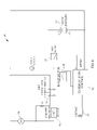
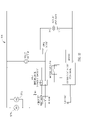
FIG. 6 wherein apower control circuit 60 is depicted providing, among other things, the boost and conserve power features of the present embodiment. The DCelectric motor 56 is shown in electrical connectivity with the various powercontrol circuit elements inter-lock handle switch 31, for example being a double pole double throw switch, acircuit breaker 28 being, as depicted herein, a 35 amp breaker, a boost/conserveswitch 26, in this example being a single pole double throw switch, apower selection switch 21, in this example being a single pole double throw switch, abattery pack 52 which is depicted as a 60 volt DC battery pack providing 60 volts presented to themotor 56 when operatively selected by thepower selection switch 21, and a hybrid AC/DC controller 100 which serves as a power inverter or step down controller for converting theline voltage 120 VAC presented by theplug 23. The battery pack is shown as sharing a common ground with other portions of the power control circuit but may be in electrical connectivity with the power control circuit in many known and understood manners without actual connected electrical wiring as long as the user operation of the lawn mower is actuated through activation of the various switches. In this present example, theboost selection switch 26 provides an increased voltage to themotor 56 by virtue of modifying an input resistive value or timing signal value to the pulse widthmodulation control unit 120, which will be described herein, in order to alter the gating of the IGBT thereby affecting the voltage wave form at the output of the power inverter or step downcontroller 100. The in rush current limiter may be provided as shown in order to prevent oversaturation of the circuit during the initial startup and energizing of the circuit. Therectifier 110 as is commonly understood rectifies the voltage from AC to DC, in this case utilizing a full bridge rectifier as shown. However, many different forms of providing a step down controller are known in the art and the depictions set forth are not to be considered unduly limiting. - As depicted in
FIG. 6 , the design consists of theAC wall plug 23 which connects to the hybrid AC/DC controller 100 acting as a voltage converter which in turn is connected to a single pole double throwpower selection switch 21 and a single pole doublethrow boost switch 26. Theboost switch 26 is the boost conserve switch depicted and described herein and it provides resistive loads to the CMOS micro-controller for the pulsewidth modulation control 120 depicted when selected and opens the contacts when off. Thepower selection switch 21 toggles the DC motor between the output of the step downcontroller 100 and the DCbattery voltage source 52. The output of thepower selection switch 21 feeds a voltage meter shown which may be connected in parallel with the double pole double throwinter-lock handle switch 31, theinter-lock handle switch 31 toggling between shorting theDC motor 56 through resister R1 to ground and connecting the output of thepower selection switch 21 through acircuit breaker 28 to theDC motor 56. - In this embodiment as depicted in
FIG. 6 , theboost switch 26 may provide increased voltage to themotor 56 when thehybrid mower 10 of the present embodiment is plugged in and running off of line voltage AC power. Such boost may be effectuated by modifying the pulsewidth modulation control 120 through alteration of the input resistive load atinput pin 7 of the micro-controller shown inFIG. 7 . More description of the power inverter and/or step downcontroller 100 of the presently inventive power supply will be set forth herein. - Turning to an additional embodiment for the
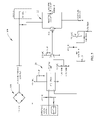
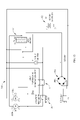
power supply circuit 160 of the present embodiment inFIG. 8 , this embodiment provides anAC wall plug 23 which connects to an AC voltage to the hybrid AC/DC controller 100 which in turn is connected to thepower selection switch 21 which allows toggling between output of the AC/DC hybrid controller 100 when in the AC selection and to a boost conserveswitch 26 and alternative power source when in the DC position. The boost conserveswitch 26 toggles between shorting the positive side of thebattery source 52 directly to theboost switch 26 went off and connecting thebattery source 52 in series with the secondary or boostbattery 64 before connecting to the power selection switch or AC/DC switch 21. Thepower selection switch 21 then feeds a voltage meter V which is connected in parallel with aninter-lock handle switch 31, here depicted as a double pole double throw switch. Theinter-lock handle switch 31 toggles between shorting theDC motor 56 through a resistor R1 to ground and connecting the output of thepower selection switch 21 through thecircuit breaker 28 to theDC motor 56. - As depicted, in the example shown in
FIG. 8 , additional voltage is provided to theDC motor 56 when the hybrid mower is positioned in the DC power selection option and activation of theboost switch 26 thereby providing an additional 6 volts DC to the 60 volts DC provided by thebattery 52. Asecondary battery 64 provides additional voltage to the motor thereby increasing the motor speed and corresponding blade speed through actuation of the boost/conserveswitch 26 to the boost setting. Thus, the power control circuit orpower supply 160 depicted inFIG. 8 allows the operator while in the DC battery operation mode to increase the operating speed of themotor 56 corresponding to the additional voltage provided by thesecondary battery 64. Controls are also provided allowing the operator to select between the operation of themotor 56 through the use of line voltage, namely 120 VAC, or through the use of thebattery pack 52. Depicted herein is asecondary boost battery 64 which is provided as separate to thebattery pack 52, but it may be more practical to provide asecondary boost battery 64 in combination with and contiguous to thebattery pack 52 as assembled and shown in the figures. Thus, thesecondary boost battery 64 may be continuous with thebattery pack 52 or may be separate but is provided to add additional voltage to themotor 56 in order to modify the operating output voltage of the power supply as presented to themotor 56. - The hybrid AC/
DC controller 100 as shown provides both power inverter and step down capabilities in order to modify and regulate the 120 VAC to the proper voltage required to run theDC motor 56. However, these functions are provided to be only exemplary. Thecontroller 100 acts as an inverter viarectifier 110 and also to properly modulate the voltage via thePWM controller 120 and associated gates. The power inverter and step downcontroller 100 may be part of the power supply orpower control module - An alternative construction for the power control is the
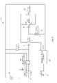
power supply circuit 260 depicted inFIG. 9 wherein both 120 VAC may be provided to supply power to themotor 56 while optionally a 60 volt DC battery may be provided as operatively selectable by the user through thepower selection switch 21 a. As depicted in this example, theboost switch 26 a is operative to bring in series asecondary battery 64 which is 6 volts DC (when set in “BOTH” mode) with the voltage provided by thehybrid controller 100 of the power supply or thebattery pack 52. Thesecondary battery 64, as previously described and as depicted in this embodiment of thepower control circuit 260, may be in combination with the battery pack or secondary and separate thereof. Additionally, as shown in the example, the 6 volt battery is brought into the circuit in series with the DC output of thehybrid control 100 or with thebattery pack 52. Also, many variations for the structure, assembly and actual value of thesecondary battery 64 for all embodiments may be provided in order to increase the voltage to themotor 56. As depicted inFIG. 9 , thepower selection switch 21 a further provides for three settings allowing user selectable options of powering theDC motor 56 by either 120 VAC, direct battery pack connection or a hybrid BOTH connection. When operating in the strictly 120 VAC mode, the hybrid AC toDC control 100 is depicted regulates and modulates the voltage for proper supplying of voltage to theDC motor 56. Alternatively, thepower selection switch 21 a provides for a DC operation whereby themotor 56 is operated merely by thebattery pack 52. A third option is placement of thepower selection switch 21 a into the BOTH mode wherein there may be a limited amount of power contribution from the battery. In such instance, voltage drops caused by increased load on themotor 56 may result in increased contribution from thebattery pack 52. Additionally, as depicted in the embodiment shown, the boost conserveswitch 26 a may be provided for contribution of additional voltage from thesecondary battery 64 when thepower selection switch 21 a is placed in either the BOTH or DC mode. In such an instance, thesecondary battery 64 is brought in series with the voltage contribution from either thepower supply 100 or thebattery pack 52. - Turning to
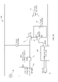
FIG. 10 , an alternative construction and embodiment of the power control andsupply circuit 360 is depicted. In the example depicted, thepower supply circuit 360 consist of a 120VAC wall plug 23 which connects to thehybrid AC controller 100 which in turn is connected to an exemplary single pole doublethrow boost switch 26 thereby allowing the circuit to bypassboost battery 64 when off or be connected to theboost battery 64 when on. Additionally, the circuit continues to an exemplary single pole double throwpower selection switch 21 which toggles between output of thespeed selection switch 26 when in the AC position and the DCbattery voltage source 52 when in the DC position. Thepower selection switch 21 feeds a voltage meter V which is connected in parallel with an exemplary double pole doublethrow inter-lock handle 31, theinter-lock handle switch 31 toggling between short in theDC motor 56 through a resistor R1 to ground and connecting the output of thepower selection switch 26 through acircuit breaker 66 to theDC motor 56. In this example of thepower control circuit 360, the boost orsecondary battery 64 is brought in parallel with thepower pack 52 or with the output of thehybrid controller 100 which may increase the current capacity for the motor when in higher speed or boost mode. - Multiple variations of power control module or power supply may be provided and are described herein. When mentioned herein as a hybrid power controller, power supply, power control module, step down controller or hybrid controller, these terms are collectively meant to imply providing electricity to the motor placed on the mower housing. No single element set forth in the exemplary embodiments provided herein, namely the power supply elements of the switches, battery packs, circuit breakers, inverters and modulation elements are to be unnecessarily applied to the interpretation of these terms. In fact, the power supply circuit collectively described herein may be implemented through the use of a significant number of alternative structures for regulation, modulation, controlling or limiting the proper voltage or power to the motor implemented in the examples herein. No unnecessary limitation should be interpreted from the particular use of the term controller, inverter, regulator or regulation or modulation as depicted herein, as one of ordinary skill in the art would be enabled through the teachings hereof to provide significant variations to the particular embodiments and examples disclosed in the figures and stated in the described examples.
- Turning to the exemplary power inverter and in combination step down
controller 100 which acts as a portion of the power control module, thehybrid controller 100 receives asinput 120 volts AC which, in this example, is inverted utilizing afull bridge rectifier 110 depicted inFIG. 7 . An in rush current limiter is provided also to prevent current surges during initial loading of the circuit and prevent further damage or over-saturation. A number of different inverter designs may be used in order to provide voltage rectification. As depicted in the present example, a full bridge rectifier may be utilized but this may be replaced with other known inverter circuitry as is available and known in the art. - In addition, as depicted in
FIG. 7 , an optional boost switch may be provided which may correspond to theboost switch 26 depicted inFIG. 6 . In the present exemplary embodiment, the boost switch may be operable to modify the input to the pulsewidth modulation controller 120 which defines the voltage output for the step downcontroller 100. As shown, a micro-controller is utilized in order to set the appropriate pulse rate for the PWM control and feeds into the insulated gate bi-polar transistor (IGBT) which provides the switching orpulse gate driver 122 for the DC output of the hybrid AC/DC control 100. Thus, thehybrid controller 100 incorporates, but does not necessarily require, the utilization of voltage rectification and a voltage rectifier as is necessary in combination with variations of voltage modification such as a pulse width modifier. However, multiple options for step down voltage and control are known and may be utilized such as diode controls, triac controls, MOSFET controls and the like. Many of these are well known in the art and may be utilized in the step down controller and power inverter in combination as described herein. Additionally, as depicted, the pulse widthmodulation control circuit 120 receives as input in one possible embodiment the ability to modify the voltage by use of the boost switch. The boost switch in this embodiment modifies the reference signal fed intopin 7 of the micro-controller for the reference value which operates to modify the gating of the IGBT and therefore, the voltage characteristics of the DC output depicted. The boost mode depicted provides the alternative function of a boost integrated with the power inverter and step down controller. As shown integrated with thecontroller 100 inFIG. 6 , the boost switch can be alternatively provided in many connections and this integrated boost switch may be integrated with many of the other alternative embodiments. - As is known, many variations of a step down controller and inverter may be utilized and in general, the power control module of the present embodiment may utilize power input of 120 VAC and which incorporates many switches and controls for electrically connecting the DC motor to either the 60 volt DC battery or the DC output of the hybrid power controller. This may include utilization of a power source switch as indicated wherein the power source switch effectively has a first power input as a connection of the power control module of the DC output of the power inverter and step down
controller 100 or receive as a second input the 60 volt DC of the battery pack, the power selection switch providing the ability of the operator to switch between 120 VAC power and 60 VDC power from the battery pack. The power selection switch may be directly connected to the DC motor, in this exemplary embodiment a 60 volt DC motor which operates the blade. The 60 volt DC motor may be operationally modified by utilization of a boost switch which is optional in many embodiments depicted herein, the boost switch changing voltage applied to the DC motor from 60 volts by an incremental value thereby increasing rotational speed of the blade as necessary by the operator. Such increase in blade speed, as previously indicated, may be necessitated by thicker grass or due to other items necessarily being mulched by thehybrid mower 10 of the present embodiment. This boost/conserve function which is shown herein provides the ability through the many embodiments disclosed to increase the voltage of the power control module and thereby increases the rotational speed of the blades. As indicated, this may be desirable for short periods of time and may provide a first power output of the power control module, the first power output higher than a second power output, the second power output being a conserve feature wherein the DC motor draws less current and thereby increases the battery life charge of the battery pack. However, such feature does not have to be implemented, as is clearly seen herein, only with the use of DC operation and DC power input as it is apparent that the increase rotational speed (boost) feature may be implemented also with 120 VAC wall power by increasing the DC voltage output of the hybrid AC/DC control 100 or by adding supplemental DC power supply from the operating batteries, whether the primary or secondary. - Turning now to
FIGS. 11-13 , an alternative embodiment of the electric lawnmower of the present invention is depicted. In such an alternative construction, theelectric lawnmower 500 has a first and a second blade 551A and 551B mounted to ahousing 550. Driving each of the blades, 551A and 551B are a first and second motor 552A and 552B as depicted inFIGS. 12 and 13 . As is commonly understood, the dual motor alternative construction as is depicted, may substantially use similar power control circuitry with the modification in the series or parallel connection of the DC motors 552A and 552B to the power supply voltage. As is understood, it is desirable to provide the DC motors with either 120VAC line power which is current rectified or with the battery pack supplied DC electrical power. In the construction and multiple embodiments provided, two blades may be provided to cut vegetation within and below thedeck 550 of theelectric lawnmower 500. A total cutting width of approximately 21 inches may be provided wherein each of the blades may be about 10.4 inches. As is commonly understood, by attempting to cut a relatively large diameter with a single blade, such as the entire 21 inches of the housing width, excessive battery drain and power consumption will be experienced due to the known issue of air movement resistance encountered by the blade. The air movement load goes up exponentially as related to the blade speed thus adding a significantly higher load in addition to the normal vegetation cutting resistance load. The faster the blade rotates and the longer the blade causes a significant proportion of the power supply to be used in movement of air as opposed to cutting of vegetation. Thus, for cutting of wider diameters, it may be preferable to utilize two motors and blades working in tandem. By utilizing two motors as opposed to a single motor with an increased rotational speed, significant power savings may be experienced and run time lengths for the power supply battery as well as power consumption in both DC and AC operations will be significantly reduced. Additionally, as is known in the art, when using dual motors 552A and 552B, such dual motor implementation may preferably not be used in series in conjunction with battery operation due to the motors running at half speed, i.e. sharing the battery pack supplied voltage in series. Thus, in preferred implementation, although not necessarily required, for dual motor use, the DC electric motors may be preferably placed in parallel as is depicted inFIG. 12 in certain operations, such as when operated by the battery pack, and possibly in series in others, such as when connected to higher line voltage. However, the DC motors may be placed in either operation as is deemed necessary. Also, power usage may not become an issue when providing line voltage through the hybrid AC to DC controller wherein the AC current is rectified for operation of the DC motors depicted. - As depicted in
FIG. 12 , the dual DC motors 552A and 552B for the power control andsupply system 520 of the present embodiment, depicts the DC motors in parallel as shown. A circuit breaker may be provided in combination with the interlock handle switch as previously described in order to operationally connect and disconnect the motors as selected by the user through the bladeclutch handle 31. Further, an AC/DC operational switch may be provided for selection of either power supply, either AC line voltage or DC battery power supply as previously described. Further, a hybrid AC/DC controller may be utilized to implement rectification of the 120 VAC to adequate supply of DC current to the motors 552A and 552B. Further, the boost switch may be provided in combination with the hybrid controller or separately as previously described as combinations of these individual elements may be selected to one of ordinary skill in the art and generally is considered to be taught within the operational specifications hereof - In an embodiment, the dual blade DC motor combination may provide a 21 inch path of cutting vegetation wherein similar rotational speeds of 16,000 to 19,000 feet per minute blade speed may be experienced either on battery or on the AC line voltage with the higher rotational speed indicated when operating using line voltage. Such rotational speed indicates a potential of 5,800 to 6,900 RPM. These speeds typify the efficiency of the motor during a non-cutting environment. In actual cutting of vegetation, the rotational speed of the blade tip may be 12,000 to 18,000 feet per minute, again with the higher rotational speeds indicated when operating on line voltage. These speeds relate to approximately 4,300 to 6,500 RPM on each of the two blades providing 21 inch cutting diameter. Similar motors may be provided as previously described for implementation of the electric lawnmower of the present invention. Further, the horsepower at cutting speed may be anywhere from 1.5 to 2.0 HP with the battery capacity of approximately 480 watt hours as necessary. Excellent cutting at these speeds with either the single motor or dual motor implementation may be experienced with adequate blade speed, cutting action and suction experienced within the lawnmower deck or housing. Mulching may also be accomplished when operating at these speeds and may be increased by implementation of the boost feature previously described which would be available to both DC electric motors during operation in this embodiment if implemented in one of the many various boost and conserver implementations previously described. Referencing again
FIG. 12 , both motors are depicted in parallel combination with the motors seeing approximately 60 volts from the power supply. When the motors are in such parallel connectivity, as one motor is loaded disproportionately due to various factors from either air resistance or vegetation and cutting resistance, the second motor slows down due to the reduced power available from the battery caused by the internal resistance and the higher amperage of the power supply as is depicted. Such self adjustment of the motor and hence blade speeds provides an automated self regulation of both motors. - Given the power supply and control embodiment depicted in
FIG. 13 , the user may select either AC or DC operation which places the twomotors battery 52 supplies constant current and may result in better performance of the motors. Further, when placed in DC mode, the motors are in parallel and as one motor is loaded disproportionately the second motor may slow down due to the reduced power available from the battery pack caused by the internal resistance of the power supply design and motor configuration and higher amperage. - Turning to the alternative construction and embodiment of the power supply and control circuitry of
FIG. 13 , the power supply andcontrol circuit 560 indicates that the dual DC motors 552A and 552B are connected to the output of the AC/DCpower selection switch 521 which toggles the power supply of the circuit from thefull bridge rectifier 501 when in the AC position and to theDC battery source 52 when in the DC position as is depicted. The output of thepower selection switch 521 feeds the voltage meter shown which is connected in parallel with the double pole, double throw interlock handleswitch 31. The interlock handleswitch 31 toggles between short in the DC motors 552A and 552B through a resistor, R1 to ground and connecting the output of thepower selection switch 521, a three pole double throw switch in this disclosed embodiment, throughcircuit breaker 28 to the dual DC motors 552A and 552B. When thepower selection switch 521 is in the AC selection position, the dual motors M1 and M2 are connected in series thereby splitting the voltage output of the rectifier. In such operation, the full bridge rectifier may provide 120VDC with 60V the seen by each motor. When the AC/DCpower selection switch 521 is in the DC position, the motors M1 and M2 are connected in parallel thereby each sharing in the DC voltage output of the battery pack. The battery, being a constant current power supply, may provide better performance of the DC motors M1 and M2 in parallel and thus the connection as is described may be provided with the capability of switching between parallel and series connectivity of the motors M1 and M2 depending on the power source. Further, as disclosed inFIG. 13 , a full bridge rectifier or possibly other current rectification is depicted wherein the 120VAC is input into the hybrid controller (not depicted as previously shown for simplicity). The full bridge rectifier in this embodiment may readily be replaced by known current rectification circuitry which have been previously disclosed herein or which are known in the art. Thus, the rectifier depicted may be replaced by other current rectification means to rectify the current from AC to DC. These known systems include but are not limited to pulse width modulation which may readily be implemented herein. - When in AC mode as selected from the user selectable power selection switch shown in
FIG. 13 , the total current going through many of the switches and electronic circuit elements presented herein may be one half of that in the parallel or battery mode given the embodiments depicted as a result of the rectification of the current and positioning of the loads. In other words, as shown inFIG. 13 , the battery pack provides 60VDC which is shared by the dual motors in parallel and the AC input line provides 120VDC to be split by the dual motors in series in the disclosed embodiments. The response to uneven loading also may be more desirable as previously described in parallel as opposed to in series mode since, when in series mode, as one motor is disproportionately loaded and slows down, the other motor will speed up. The actual speed modification of the motors in series however may be mitigated due to the nature of the air resistance to the blades and the significant amount of energy and load required to move the air in the mower housing. The relationship between air movement resistance and blade speed is an exponential relationship thus adding a significantly higher load the faster the blade thus tending to cause the blades to operate at similar speeds in these embodiments. However, either combination of either series or parallel connection of the two DC motors as is depicted may readily be implemented and such a description is set forth herein is not deemed limiting as a preferable implementation as one of ordinary skill in the art may implement series or parallel connectivity of the motor as the system necessarily requires. - In both configurations of the dual motor design depicted, the ability and functionality of the boost and conserve features are still present in that the blade speed for both motors may be reduced in a conserve mode, particularly when operating off of the DC battery power supply in order to increase charge life. As shown in
FIG. 12 , a boost and conserve switch and feature may be implemented in conjunction with the hybrid controller shown. However, many differing combinations of the boost and conserve feature previously described may be well understood to be applicable to either design and power supply shown. In conjunction with the power supply and control depicted in either embodiment, a secondary battery pack may be utilized as discussed herein to increase the voltage output of the DC operation and power supply thereby increasing the blade speed for both motors while also allowing battery use to be conserved in a second state thereby increasing overall run life per charge. Alternatively, increased voltage may be provided directly from the hybrid controller as depicted when drawing power from AC power supply. Similarly alternative constructions may be implemented in the embodiment shown in the various Figures and embodiments. - Many configurations are available for the hybrid mower discussed herein. While the hybrid mower has been described for many embodiments, the invention presented is not limited to the specific structures provided. The invention and claims are intended to cover various modifications and equivalent arrangements included within the spirit and scope of the appended claims and teachings hereof The scope of the claims is to be accorded the broadest interpretation so as to encompass all such modifications and equivalent structures and functions.
Claims (19)
Priority Applications (9)
| Application Number | Priority Date | Filing Date | Title |
|---|---|---|---|
| US11/670,932 US7728534B2 (en) | 2006-10-17 | 2007-02-02 | Hybrid electric lawnmower |
| US11/899,616 US20080120955A1 (en) | 2006-10-17 | 2007-09-05 | Hybrid electric lawnmower |
| US11/906,546 US20080086997A1 (en) | 2006-10-17 | 2007-10-01 | Hybrid electric device |
| US11/906,541 US7884560B2 (en) | 2006-10-17 | 2007-10-01 | Hybrid electric device |
| PCT/US2007/022101 WO2008048615A2 (en) | 2006-10-17 | 2007-10-16 | Hybrid electric device |
| PCT/US2007/022107 WO2008048618A2 (en) | 2006-10-17 | 2007-10-16 | Hybrid electric device |
| US12/077,079 US8732896B2 (en) | 2006-10-17 | 2008-03-14 | Hybrid electric cleaning device |
| US12/077,049 US7741793B2 (en) | 2006-10-17 | 2008-03-14 | Hybrid electric device |
| US14/282,806 US9787225B2 (en) | 2006-10-17 | 2014-05-20 | Hybrid electric device |
Applications Claiming Priority (3)
| Application Number | Priority Date | Filing Date | Title |
|---|---|---|---|
| US11/550,104 US7479754B2 (en) | 2006-10-17 | 2006-10-17 | Hybrid electric lawnmower |
| US11/550,476 US7482768B2 (en) | 2006-10-17 | 2006-10-18 | Hybrid electric lawnmower having dual power supply |
| US11/670,932 US7728534B2 (en) | 2006-10-17 | 2007-02-02 | Hybrid electric lawnmower |
Related Parent Applications (2)
| Application Number | Title | Priority Date | Filing Date |
|---|---|---|---|
| US11/550,104 Continuation-In-Part US7479754B2 (en) | 2006-10-17 | 2006-10-17 | Hybrid electric lawnmower |
| US11/550,476 Continuation-In-Part US7482768B2 (en) | 2006-10-17 | 2006-10-18 | Hybrid electric lawnmower having dual power supply |
Related Child Applications (1)
| Application Number | Title | Priority Date | Filing Date |
|---|---|---|---|
| US11/899,616 Continuation-In-Part US20080120955A1 (en) | 2006-10-17 | 2007-09-05 | Hybrid electric lawnmower |
Publications (2)
| Publication Number | Publication Date |
|---|---|
| US20080098703A1 true US20080098703A1 (en) | 2008-05-01 |
| US7728534B2 US7728534B2 (en) | 2010-06-01 |
Family
ID=39328495
Family Applications (1)
| Application Number | Title | Priority Date | Filing Date |
|---|---|---|---|
| US11/670,932 Active 2028-03-20 US7728534B2 (en) | 2006-10-17 | 2007-02-02 | Hybrid electric lawnmower |
Country Status (1)
| Country | Link |
|---|---|
| US (1) | US7728534B2 (en) |
Cited By (14)
| Publication number | Priority date | Publication date | Assignee | Title |
|---|---|---|---|---|
| US20100275564A1 (en) * | 2008-04-25 | 2010-11-04 | Florin Baetica | Mower |
| US20110088362A1 (en) * | 2008-04-25 | 2011-04-21 | Rosa Richard P | Mower |
| US8336282B2 (en) * | 2010-07-28 | 2012-12-25 | Deere & Company | Robotic mower housing |
| US20130167495A1 (en) * | 2009-04-17 | 2013-07-04 | Positec Power Tools (Suzhou) Co., Ltd. | Self-propelled lawn mower |
| US20130239533A1 (en) * | 2012-03-07 | 2013-09-19 | Robert Bosch Gmbh | Lawn-care apparatus |
| US20140067172A1 (en) * | 2012-08-31 | 2014-03-06 | Troy W. Harris, III | Electric Lawn Tractor Power Management System And Method |
| CN104798542A (en) * | 2015-03-24 | 2015-07-29 | 浙江亚特电器有限公司 | Double-power mowing machine |
| US9254563B2 (en) | 2010-06-08 | 2016-02-09 | Hitachi Koki Co., Ltd. | Power tool |
| CN107072148A (en) * | 2014-11-14 | 2017-08-18 | 创科实业有限公司 | Mixed type ac/dc hay mover with ac/dc converting system |
| WO2018039171A1 (en) * | 2016-08-22 | 2018-03-01 | Sunrise Global Marketing | Air compressor and method of operation |
| US9991825B1 (en) * | 2014-11-24 | 2018-06-05 | The Toro Company | Outdoor power equipment system with modular motor and modular battery |
| US10230078B2 (en) * | 2016-11-30 | 2019-03-12 | Honda Motor Co., Ltd. | Electric power equipment |
| US11258218B2 (en) * | 2018-08-02 | 2022-02-22 | Kubota Corporation | Battery connector assembly and battery device |
| US11889794B2 (en) | 2020-12-30 | 2024-02-06 | Milwaukee Electric Tool Corporation | Handheld blower |
Families Citing this family (22)
| Publication number | Priority date | Publication date | Assignee | Title |
|---|---|---|---|---|
| US9722334B2 (en) * | 2010-04-07 | 2017-08-01 | Black & Decker Inc. | Power tool with light unit |
| US20130069578A1 (en) * | 2011-09-21 | 2013-03-21 | Chao-Chin Yao | Brushless Ceiling Fan Motor Power Control System |
| EP2763878B1 (en) * | 2011-10-03 | 2020-08-05 | Husqvarna Ab | Battery powered vehicle with immobilizing charger plug |
| US8727233B2 (en) | 2011-10-17 | 2014-05-20 | Champion Power Equipment, Inc. | Pressure spray washer and control |
| US9127658B2 (en) | 2011-11-04 | 2015-09-08 | Briggs & Stratton Corporation | Internal combustion engine including starting system powered by lithium-ion battery |
| US8733072B2 (en) | 2011-11-04 | 2014-05-27 | Briggs & Stratton Corporation | Starter system for an engine |
| US8857138B2 (en) | 2011-11-04 | 2014-10-14 | Briggs & Stratton Corporation | Starter system for an engine |
| US9427859B2 (en) | 2013-01-08 | 2016-08-30 | Techtrnoic Outdoor Products Technology Limited | Motor system for dual voltage devices |
| US10130962B2 (en) | 2013-10-10 | 2018-11-20 | Briggs & Stratton Corporation | Wirelessly controlled trigger start and chemical tank change-over for pressure washers |
| US9338940B2 (en) | 2014-02-27 | 2016-05-17 | Honda Motor Co., Ltd. | Drive systems and methods for implementing engine stall protection in a self-propelled machine |
| EP3114717A1 (en) | 2014-03-06 | 2017-01-11 | Briggs & Stratton Corporation | Rechargeable battery system for replacement of lead-acid battery |
| CN105471146A (en) | 2014-09-04 | 2016-04-06 | 苏州宝时得电动工具有限公司 | Electric tool |
| US9616893B2 (en) | 2014-10-15 | 2017-04-11 | Honda Motor Co., Ltd. | Automatic turn-sensing ground speed reduction systems and related methods for walk-behind machines |
| CN104969722B (en) * | 2015-06-11 | 2017-07-07 | 浙江亚特电器有限公司 | A kind of power-operated mower |
| US10063097B2 (en) | 2015-10-16 | 2018-08-28 | Kohler Co. | Segmented waveform converter on controlled field variable speed generator |
| US10778123B2 (en) | 2015-10-16 | 2020-09-15 | Kohler Co. | Synchronous inverter |
| US10148207B2 (en) | 2015-10-16 | 2018-12-04 | Kohler Co. | Segmented waveform converter on controlled field variable speed generator |
| US10148202B2 (en) | 2015-10-16 | 2018-12-04 | Kohler Co. | Hybrid device with segmented waveform converter |
| USD795181S1 (en) | 2016-06-15 | 2017-08-22 | Briggs & Stratton Corporation | Battery |
| USD833486S1 (en) | 2017-09-07 | 2018-11-13 | The Toro Company | Lawn mower powerhead |
| US11173780B2 (en) | 2018-01-04 | 2021-11-16 | Delta Systems, Inc. | Hybrid mower with electric blade control system |
| US11427091B1 (en) | 2019-04-29 | 2022-08-30 | Parker-Hannifin Corporation | Electric drive system for a mower |
Citations (92)
| Publication number | Priority date | Publication date | Assignee | Title |
|---|---|---|---|---|
| US1490127A (en) * | 1921-04-09 | 1924-04-15 | John W Peters | Lawn mower |
| US1954579A (en) * | 1930-10-03 | 1934-04-10 | Smith Robert Bigham | Electric lawn mower |
| US2185659A (en) * | 1938-09-02 | 1940-01-02 | Chernow Paul | Automatic electric lawn mower |
| US2237521A (en) * | 1939-11-06 | 1941-04-08 | Pearl G Frazier | Power unit for driving lawn mowers |
| US2417613A (en) * | 1944-08-22 | 1947-03-18 | John M Radabaugh | Electric motor control and differential gear drive for lawn mowers |
| US2458200A (en) * | 1946-05-03 | 1949-01-04 | Lester C Renfroe | Electric lawn mower and hedge clipper |
| US2498609A (en) * | 1948-01-12 | 1950-02-21 | Reil Ben | Automatic electric wire roller for electric power lawn mowers |
| US2498796A (en) * | 1946-08-30 | 1950-02-28 | Milton B Downer | Lawn mower |
| US2547328A (en) * | 1946-03-09 | 1951-04-03 | Erich J Koch | Lawn shaver |
| US2549317A (en) * | 1946-08-06 | 1951-04-17 | Myron P Laughlin | Lawn mower |
| US2592856A (en) * | 1950-04-03 | 1952-04-15 | Clarence E Brockman | Handle means and support structure for power lawn mowers |
| US2633688A (en) * | 1952-02-12 | 1953-04-07 | Huffman Mfg Company | Lawn mower handle extension for electric cord |
| US2700862A (en) * | 1953-06-24 | 1955-02-01 | Huffman Mfg Company | Lawn mower with safety device |
| US2702448A (en) * | 1953-08-19 | 1955-02-22 | Smith Philip | Battery powered disk type lawn mower |
| US2867960A (en) * | 1955-05-13 | 1959-01-13 | Silex Co | Lawn trimmer and edger with wheel adjusting means |
| USRE24594E (en) * | 1959-01-27 | Battery powered disk type lawn mower | ||
| US2926478A (en) * | 1956-03-28 | 1960-03-01 | Sunbeam Corp | Multiple blade rotary power mower |
| US2929926A (en) * | 1957-04-10 | 1960-03-22 | Motorola Inc | Radio receiver with automatic gain control operating over wide range |
| US2970419A (en) * | 1958-10-07 | 1961-02-07 | Lieberman Samuel | Turf edge trimmer and hedge clipper |
| US2979878A (en) * | 1960-05-20 | 1961-04-18 | Louis J Kaposta | Rotary mower for producing scalloped cutting effect |
| US3017733A (en) * | 1959-10-27 | 1962-01-23 | Elmer E Evans | Lawn edger |
| US3028717A (en) * | 1957-07-31 | 1962-04-10 | Scott & Sons Co O M | Power mower |
| US3077066A (en) * | 1960-12-19 | 1963-02-12 | Warren K Van Hook | Lawn mower |
| US3128840A (en) * | 1962-04-23 | 1964-04-14 | Barrett Electronics Corp | Random control for power-driven unit |
| US3230695A (en) * | 1957-07-31 | 1966-01-25 | Scott & Sons Co O M | Safety controls for an electrical powered lawn mower |
| US3298163A (en) * | 1961-08-28 | 1967-01-17 | Sunbeam Corp | Rotary electric lawn mower |
| US3375338A (en) * | 1965-12-17 | 1968-03-26 | Atlas Tool & Mfg Company | Extension cord control assembly for electric mower |
| US3496706A (en) * | 1967-07-12 | 1970-02-24 | Sunbeam Corp | Electric rotary lawnmower and grass collection bag |
| US3500085A (en) * | 1969-02-26 | 1970-03-10 | Ambac Ind | Electric motor and rectifier assembly |
| US3500620A (en) * | 1967-05-05 | 1970-03-17 | Black & Decker Mfg Co | Electric lawnmower construction |
| US3564186A (en) * | 1968-09-04 | 1971-02-16 | Toro Mfg Corp | Switch control mechanism |
| US3570226A (en) * | 1967-08-05 | 1971-03-16 | Hanning Elektro Werke | Electrically driven lawnmower |
| US3570227A (en) * | 1969-01-16 | 1971-03-16 | Mowbot Inc | Self-propelled random motion lawnmower |
| US3631659A (en) * | 1969-06-18 | 1972-01-04 | Philips Corp | Lawn mower |
| US3641749A (en) * | 1970-10-05 | 1972-02-15 | Black & Decker Mfg Co | Baffle for electric lawnmower |
| US3789939A (en) * | 1971-09-07 | 1974-02-05 | E Geislinger | Apparatus for programming movement of a cart |
| US4003190A (en) * | 1975-08-07 | 1977-01-18 | Briggs & Stratton Corporation | Safety device for walk-behind rotary mowers |
| US4008423A (en) * | 1975-02-11 | 1977-02-15 | Gould Inc. | Electrically propelled vehicle |
| US4081737A (en) * | 1975-06-03 | 1978-03-28 | Hiroyasu Miyahara | Secondary battery charger and heater |
| US4145864A (en) * | 1977-01-06 | 1979-03-27 | Brewster Jr Albert H | Battery powered lawnmower |
| US4181206A (en) * | 1978-01-23 | 1980-01-01 | Briggs & Stratton Corporation | Back-up safety system for machine having rotatable part declutched by dead man control |
| US4244160A (en) * | 1978-12-21 | 1981-01-13 | Deere & Company | Ignition interlock system for self-propelled walk-behind lawn mower |
| US4318266A (en) * | 1980-12-15 | 1982-03-09 | Max Taube | Remotely controlled self-propelled power lawn mower |
| US4321523A (en) * | 1978-10-05 | 1982-03-23 | The Gates Rubber Company | Battery charger and power supply circuitry |
| US4371906A (en) * | 1979-06-28 | 1983-02-01 | Black & Decker Inc. | Overspeed protective apparatus for a portable tool |
| US4430604A (en) * | 1982-03-24 | 1984-02-07 | Echlin Inc. | Rectifier switch for electric lawn mowers |
| US4503370A (en) * | 1982-10-26 | 1985-03-05 | Black & Decker Inc. | Electronic clutch for electric tools of selectable speed |
| US4893067A (en) * | 1987-05-06 | 1990-01-09 | Black & Decker Inc. | Direct current motor speed control |
| US4905300A (en) * | 1987-05-21 | 1990-02-27 | Black & Decker Inc. | Motor control and power systems and methods of operation thereof |
| US4987729A (en) * | 1990-04-10 | 1991-01-29 | Paytas Anthony R | Solar powered mower |
| US4990843A (en) * | 1988-06-27 | 1991-02-05 | Electrolux Mecatronik Aktiebolag | Reluctance motor |
| US5085043A (en) * | 1990-06-01 | 1992-02-04 | Black & Decker Inc. | Electro-mechanical interlock and module system for lawn mower or other electrical device |
| US5086491A (en) * | 1989-11-24 | 1992-02-04 | Black & Decker, Inc. | Electronic control circuit for a/c motors |
| USD333309S (en) * | 1990-06-01 | 1993-02-16 | Black & Decker, Inc. | Lawn mower with bag |
| US5379991A (en) * | 1992-02-12 | 1995-01-10 | Gerb Schwingungsisolierungen Gmbh & Co. Kg. | Horizontally and vertically acting viscous vibration damper |
| US5388176A (en) * | 1992-04-06 | 1995-02-07 | Briggs & Stratton Corp. | DC motor speed control system |
| USD356581S (en) * | 1993-10-20 | 1995-03-21 | Ryobi Motor Products, Corp. | Electric lawn mower |
| US5490370A (en) * | 1992-08-18 | 1996-02-13 | Black & Decker Inc. | Battery operated electric machines |
| US5602459A (en) * | 1988-07-13 | 1997-02-11 | Electronic Development Inc. | Fuel saving multi-battery charging system and method |
| US5606851A (en) * | 1993-09-22 | 1997-03-04 | Briggs & Stratton Corporation | Battery-powered lawn cutting system |
| US5610499A (en) * | 1988-07-13 | 1997-03-11 | Electronic Development, Inc. | Multi-battery fuel saving and emission reduction system for automotive vehicles |
| US5713189A (en) * | 1995-08-16 | 1998-02-03 | Ransomes America Corporation | Interactive brake system for electric riding mower |
| USD390576S (en) * | 1996-06-11 | 1998-02-10 | Makita Corporation | Mower |
| US5727372A (en) * | 1996-05-30 | 1998-03-17 | The Toro Company | On-board charging system for electric lawn mower |
| US5731673A (en) * | 1993-07-06 | 1998-03-24 | Black & Decker Inc. | Electrical power tool having a motor control circuit for increasing the effective torque output of the power tool |
| US5730397A (en) * | 1996-08-09 | 1998-03-24 | Van Niekerk; Phillippus Rudolf | Electric lawnmower cable supporting device |
| US5864223A (en) * | 1996-11-05 | 1999-01-26 | Meyer; Dennis R. | Battery life extender apparatus |
| USD419163S (en) * | 1995-07-24 | 2000-01-18 | Black & Decker Inc. | Mower shroud |
| US6018231A (en) * | 1997-10-02 | 2000-01-25 | Black & Decker Inc. | Battery charging system |
| US6018937A (en) * | 1997-01-14 | 2000-02-01 | Honda Giken Kogyo Kabushiki Kaisha | Lawn maintenance apparatus having a rotatable, key operated switch |
| US6019010A (en) * | 1996-01-10 | 2000-02-01 | Jeffrey Robert Lucking | Gear-selection mechanisms and a gearbox |
| USD421265S (en) * | 1997-08-27 | 2000-02-29 | Honda Giken Kogyo Kabushiki Kaisha | Lawn mower |
| US6039598A (en) * | 1998-01-26 | 2000-03-21 | Mtd Products Inc. | Electric equipment interconnection |
| US6170241B1 (en) * | 1996-04-26 | 2001-01-09 | Tecumseh Products Company | Microprocessor controlled motor controller with current limiting protection |
| US6172437B1 (en) * | 1999-04-07 | 2001-01-09 | Black & Decker Inc. | Hybrid AC/DC motor |
| US6170173B1 (en) * | 1999-05-18 | 2001-01-09 | Gayford Caston | Method and apparatus for fluid flow transfer in shoes |
| US6195970B1 (en) * | 1996-04-10 | 2001-03-06 | WOLF-GERäTE VERTRIEBSGESELLSCHAFT GMBH KG | Tool with an electric motor as the drive |
| US6202396B1 (en) * | 1998-06-16 | 2001-03-20 | Black & Decker Inc. | Lawn mower wheel mechanism |
| US6359344B1 (en) * | 2000-09-12 | 2002-03-19 | Lincoln Global, Inc. | Electric generating domestic implement |
| US6523334B1 (en) * | 2000-10-26 | 2003-02-25 | Textron Inc. | Battery-powered walk-behind greensmower |
| US6525509B1 (en) * | 1998-01-08 | 2003-02-25 | Aktiebolaget Electrolux | Docking system for a self-propelled working tool |
| US6531850B1 (en) * | 2001-08-20 | 2003-03-11 | Deere & Company | Load controller utilizing alternator field excitation |
| US6707268B1 (en) * | 2002-10-15 | 2004-03-16 | Arvinmeritor Technology, Llc | Alternative drive power arrangement having an electric motor with multiple armatures |
| US6850029B1 (en) * | 1999-08-17 | 2005-02-01 | Black & Decker, Inc. | Electrical machines |
| US6857253B2 (en) * | 1995-11-13 | 2005-02-22 | Ransomes America Corporation | Electric riding mower with motor generator set and noise abatement |
| US6983583B2 (en) * | 2003-11-21 | 2006-01-10 | Ariens Company | Lawnmower tilt sensor apparatus and method |
| US6987328B2 (en) * | 2002-11-22 | 2006-01-17 | Honda Motor Company, Ltd. | Power equipment apparatus having a power generation system |
| USD513756S1 (en) * | 2004-08-11 | 2006-01-24 | Gardena Manufacturing Gmbh | Lawnmower |
| US7007446B2 (en) * | 2000-10-26 | 2006-03-07 | Textron Inc. | Battery-powered walk-behind greensmower |
| US7015662B2 (en) * | 2003-02-28 | 2006-03-21 | Honda Motor Co. Ltd. | Engine operated machine |
| US7017327B2 (en) * | 2003-12-10 | 2006-03-28 | Deere & Company | Hybrid electric tool carrier |
| US7168227B2 (en) * | 2004-05-21 | 2007-01-30 | Textron Inc. | Internal combustion engine traction drive with electric cutting unit drive for walking greens mower |
Family Cites Families (213)
| Publication number | Priority date | Publication date | Assignee | Title |
|---|---|---|---|---|
| USRE18944E (en) | 1933-09-12 | Power operated lawn mower | ||
| US963146A (en) | 1909-09-04 | 1910-07-05 | William W Harrison | Motor-driven lawn-mower. |
| US1115350A (en) | 1913-08-28 | 1914-10-27 | Timothy D Vincent | Lawn-mower. |
| US1383178A (en) | 1920-02-02 | 1921-06-28 | William E Voges | Tractor lawn-cutter |
| US1357396A (en) | 1920-02-06 | 1920-11-02 | Gater Roy | Lawn-mower |
| US1401156A (en) | 1920-06-05 | 1921-12-27 | Moto Mower Company | Lawn-mower |
| US1387578A (en) | 1920-06-07 | 1921-08-16 | Emil E Yost | Power-driven lawn-mower |
| US1558465A (en) | 1923-04-06 | 1925-10-27 | Herbert H Dahl | Lawn mower |
| US1603637A (en) | 1924-12-08 | 1926-10-19 | Ott Charles Walter | Electric lawn mower |
| US1567055A (en) | 1925-03-28 | 1925-12-29 | Huff Mfg Company | Electric lawn mower |
| US1674847A (en) | 1925-07-20 | 1928-06-26 | Henry Watson & Sons Ltd | Electrically-driven lawn mower |
| US1643656A (en) | 1925-10-01 | 1927-09-27 | Coldwell Lawn Mower Company | Electric lawn mower |
| US1669471A (en) | 1926-08-03 | 1928-05-15 | Electric Vacuum Lawn Mower Com | Vacuum lawn mower |
| US1725487A (en) | 1927-10-05 | 1929-08-20 | Steinmetz Electric Lawn Mower | Lawn mower |
| US1819791A (en) | 1927-11-17 | 1931-08-18 | Reed Matthew Howard | Power unit adapted to be applied to lawn mowers |
| US1827559A (en) | 1929-06-15 | 1931-10-13 | Beazley Power Mower Co | Power operated lawn mower |
| US1823215A (en) | 1929-09-21 | 1931-09-15 | William D Seal | Electric lawn mower and hedge trimmer |
| US1866380A (en) | 1930-10-08 | 1932-07-05 | Glow Electric Company | Lawn mower |
| US1829690A (en) | 1931-01-12 | 1931-10-27 | Alvin M Turner | Electric lawn mower |
| US2052535A (en) | 1936-03-26 | 1936-08-25 | Smith Corp A O | Automobile frame |
| US2167222A (en) | 1938-08-01 | 1939-07-25 | Richmond Foundry & Mfg Co Inc | Lawn mower |
| US2298135A (en) | 1940-10-31 | 1942-10-06 | William C Klein | Rotary reel electric lawn mower |
| US2469022A (en) | 1945-05-22 | 1949-05-03 | Walker Ronald William | Computer for determining the correct proportions of ingredients for a selected mixture |
| US2514278A (en) | 1945-09-04 | 1950-07-04 | Dunn Albert | Mowing apparatus |
| US2485729A (en) | 1946-01-03 | 1949-10-25 | George A Gentry | Rotary grass cutter |
| US2597735A (en) | 1946-09-13 | 1952-05-20 | Sunbeam Corp | Lawn mower |
| US2480944A (en) | 1947-02-19 | 1949-09-06 | John J Malpass | Electric lawn mower |
| US2521262A (en) | 1947-09-25 | 1950-09-05 | William T Smith | Electric motor-driven lawn mower |
| US2554790A (en) | 1948-09-09 | 1951-05-29 | Hays Mfg Co | Flow control device |
| US2708977A (en) | 1950-08-02 | 1955-05-24 | John J Scheppe | Lawn mower electric driving and steering control mechanism |
| US2709882A (en) | 1951-04-20 | 1955-06-07 | Huffman Mfg Company | Lawn mower control apparatus |
| US2690892A (en) | 1951-06-15 | 1954-10-05 | Bar Samuel W La | Electric lawn mower extension cord bar |
| US2724229A (en) | 1952-07-31 | 1955-11-22 | Wallis W Graham | Rotary lawn trimmer with skids |
| US2728182A (en) | 1953-01-09 | 1955-12-27 | Roy B Fulton | Electric lawn mower with automatic reel |
| US2716559A (en) | 1953-01-19 | 1955-08-30 | Johnston Lawn Mower Corp | Reversible handle for lawn mowers and the like |
| US2941346A (en) | 1953-11-02 | 1960-06-21 | Perry Edward Gordon | Method and apparatus for the remote control of a lawn mower |
| US2770085A (en) | 1953-12-11 | 1956-11-13 | Myron P Laughlin | Power mower with frusto-spherical ground shoe |
| US2766573A (en) | 1954-01-04 | 1956-10-16 | Gen Motors Corp | Mower with air-cooled electric motor and cutting disc |
| US2793484A (en) | 1954-03-09 | 1957-05-28 | Huffman Mfg Company | Rotary disc mower cutter mounting means |
| US2793485A (en) | 1954-04-05 | 1957-05-28 | Porter Cable Machine Co | Grass trimmer |
| US2763116A (en) | 1954-08-04 | 1956-09-18 | Donald E Flinchbaugh | Wheel mounting for lawn mower |
| US2938323A (en) | 1956-02-07 | 1960-05-31 | Brown & Root | Combined mower, edger, and trimmer |
| US2906081A (en) | 1957-03-15 | 1959-09-29 | Clifford H Flanigan | Blade speed controller for electric lawn mower |
| US2908128A (en) | 1957-11-26 | 1959-10-13 | Daniel A Mauro | Cutting device for rotary mowers |
| US2909885A (en) | 1958-05-21 | 1959-10-27 | Smith Philip | Battery powered disk type lawn mower |
| US2983057A (en) | 1958-07-07 | 1961-05-09 | Albert H Erickson | Blower head attachment for a rotary lawn mower |
| US3034275A (en) | 1958-07-28 | 1962-05-15 | Diehl Mfg Co | Combination unit grass edger and trimmer |
| US2942397A (en) | 1958-09-15 | 1960-06-28 | Charley E Clark | Power-driven, grass-cutting and grassrenovating machine |
| US3035386A (en) | 1958-11-12 | 1962-05-22 | Sunbeam Corp | Power operated lawn mower |
| US3217824A (en) | 1961-05-11 | 1965-11-16 | Jepson Ivar | Electric lawn mower with improved grounding means |
| US3144258A (en) | 1961-08-28 | 1964-08-11 | Sunbeam Corp | Rotary electric lawn mower |
| US3147987A (en) | 1962-08-22 | 1964-09-08 | Sunbeam Corp | Adjustable wheel support for a lawn mower |
| US3212244A (en) | 1963-03-07 | 1965-10-19 | Barton M Wilgus | Power mower |
| US3221481A (en) | 1963-08-19 | 1965-12-07 | Sunbeam Corp | Combination lawn edger and trimmer |
| US3271939A (en) | 1963-12-19 | 1966-09-13 | Union Carbide Corp | Powered unit for a lawn mower or similar device |
| US3550714A (en) | 1964-10-20 | 1970-12-29 | Mowbot Inc | Lawn mower |
| US3350864A (en) | 1965-03-26 | 1967-11-07 | Black & Decker Mfg Co | Power-operated lawn trimmer-edger |
| US3456430A (en) | 1966-07-05 | 1969-07-22 | Sunbeam Corp | Electric rotary lawnmower |
| US3485017A (en) | 1967-03-17 | 1969-12-23 | Black & Decker Mfg Co | Folding handle for lawn mower |
| US3485018A (en) | 1967-04-04 | 1969-12-23 | Black & Decker Mfg Co | Lawn mower deck housing |
| US3481123A (en) | 1967-04-10 | 1969-12-02 | Black & Decker Mfg Co | Handle mount for lawn mower |
| US3696593A (en) | 1968-09-04 | 1972-10-10 | Toro Mfg Corp | Electric start for mowers |
| US3593505A (en) | 1968-09-04 | 1971-07-20 | Toro Mfg Corp | Mower motor cooling system |
| US3583138A (en) | 1968-10-02 | 1971-06-08 | Sunbeam Corp | Lawn mower grass bag |
| US3593950A (en) | 1968-10-15 | 1971-07-20 | Toro Mfg Corp | Cord strain relief device |
| US3659170A (en) | 1968-12-13 | 1972-04-25 | Mcculloch Corp | Direct coupled power sources and braking means for tools such as lawn mowers |
| US3603065A (en) | 1969-09-26 | 1971-09-07 | Black & Decker Mfg Co | Cam safe switch actuator |
| US3581480A (en) | 1969-09-30 | 1971-06-01 | Black & Decker Mfg Co | Multiple-function receptacle and interconnecting plugs therefor |
| US3613338A (en) | 1969-10-01 | 1971-10-19 | Black & Decker Mfg Co | Lawn mower handle mounting assembly |
| US3657868A (en) | 1970-03-23 | 1972-04-25 | Thermad Inc | Impact actuated mowing machine |
| US3617786A (en) | 1970-05-13 | 1971-11-02 | Black & Decker Mfg Co | Electric motor commutator end construction |
| US3732671A (en) | 1971-08-31 | 1973-05-15 | Deere & Co | Electric drive riding mower |
| US3731471A (en) | 1972-03-22 | 1973-05-08 | Deere & Co | Safe starting system for lawn and garden equipment |
| US3733794A (en) | 1972-03-22 | 1973-05-22 | Deere & Co | Safe starting system for lawn and garden equipment |
| US3800902A (en) | 1972-09-26 | 1974-04-02 | R Keller | Method and apparatus for the control of self-propelled apparatus |
| US3924389A (en) | 1973-03-27 | 1975-12-09 | Stanley B Kita | Automatic lawn mower |
| US3955653A (en) | 1974-04-25 | 1976-05-11 | The Toro Company | Rotary mower blade arrester apparatus |
| US3948024A (en) | 1974-09-20 | 1976-04-06 | Deere & Company | Implement position control system |
| US3970913A (en) | 1974-12-16 | 1976-07-20 | Briggs & Stratton Corporation | State-of-charge indicator for voltage-regulated battery charger |
| US3916280A (en) | 1975-01-09 | 1975-10-28 | Briggs & Stratton Corp | Battery charger with state-of-charge indicator |
| US3980068A (en) | 1975-03-25 | 1976-09-14 | Jacobsen Manufacturing Company | Gasoline powered machine having two electric circuit switches |
| US3969875A (en) | 1975-04-18 | 1976-07-20 | Mtd Products Inc. | Safety grounding circuits |
| USD249266S (en) | 1977-02-24 | 1978-09-05 | Fuso Keigokin Co., Ltd. | Lawn mower |
| US4178741A (en) | 1978-08-17 | 1979-12-18 | The Toro Company | Safety system for riding mower |
| US4236494A (en) | 1978-09-21 | 1980-12-02 | Outboard Marine Corporation | Electronically controlled C.D. ignition and interlocking shut-off system |
| US4294327A (en) | 1978-12-15 | 1981-10-13 | Delta Systems, Inc. | Safety interlock for machine and engine with magneto ignition |
| US4267914A (en) | 1979-04-26 | 1981-05-19 | Black & Decker Inc. | Anti-kickback power tool control |
| US4307325A (en) | 1980-01-28 | 1981-12-22 | Black & Decker Inc. | Digital control system for electric motors in power tools and the like |
| US4412158A (en) | 1980-02-21 | 1983-10-25 | Black & Decker Inc. | Speed control circuit for an electric power tool |
| US4333302A (en) | 1981-03-13 | 1982-06-08 | Ronald Thomas | Combined A.C./D.C. electric lawn mower |
| US4447786A (en) | 1982-02-12 | 1984-05-08 | Black & Decker Inc. | Waveform synthesizer and motor controller |
| US4489267A (en) | 1982-02-12 | 1984-12-18 | Black & Decker Inc. | Waveform synthesizer and motor controller |
| NL8204628A (en) | 1982-11-30 | 1984-06-18 | Philips Nv | DEVICE FOR SIGNALING A PARTICULAR CHARGING STATE OF A BATTERY BATTERY. |
| US4527101A (en) | 1983-11-23 | 1985-07-02 | Black & Decker Inc. | Universal electric motor speed sensing by using Fourier transform method |
| US4628233A (en) | 1984-03-23 | 1986-12-09 | Black & Decker Inc. | Microprocessor based motor control |
| US4550277A (en) | 1984-09-24 | 1985-10-29 | Black & Decker Inc. | Overload detection and warning system for electric motors in power tools and the like |
| GB8611932D0 (en) | 1986-05-16 | 1986-06-25 | Ransomes Sims & Jefferies Plc | Grass cutting machine |
| USRE33376E (en) | 1987-05-29 | 1990-10-09 | International Paper Company | Non-foil composite structures for packaging juice |
| US4764715A (en) | 1987-06-15 | 1988-08-16 | Motorola, Inc. | Electronic service timer for an appliance |
| US4887415A (en) | 1988-06-10 | 1989-12-19 | Martin Robert L | Automated lawn mower or floor polisher |
| US4870811A (en) | 1988-11-28 | 1989-10-03 | Steele Robert M | Gasoline powered electrical lawn mower |
| US5028853A (en) | 1989-01-23 | 1991-07-02 | Square D Company | Switch actuation circuit and arrangement |
| SE464213B (en) | 1989-07-28 | 1991-03-18 | Electrolux Mecatronik Ab | PROCEDURE AND DEVICE FOR SENSOR-FREE CONTROL OF AN ELECTRIC ENGINE |
| US4964265A (en) | 1989-09-11 | 1990-10-23 | Young Carl W | Remotely controlled lawn mower |
| US5227710A (en) | 1989-12-28 | 1993-07-13 | The Alexander J. Lewus Revocable Inter Vivos (Living) Trust | Multiple speed single phase motor |
| USD330210S (en) | 1990-06-01 | 1992-10-13 | Black & Decker, Inc. | Lawn mower |
| US5208519A (en) | 1991-02-07 | 1993-05-04 | Briggs & Stratton Corporation | Electronic speed governor |
| JP3037794B2 (en) | 1991-09-25 | 2000-05-08 | 本田技研工業株式会社 | Glass harvester full detection device for reapers |
| US5325650A (en) | 1991-10-31 | 1994-07-05 | Honda Giken Kogyo Kabushiki Kaisha | Apparatus for controlling traveling of mower |
| AU116042S (en) | 1992-01-21 | 1992-12-22 | Ryobi Ltd | Electric mowing machine |
| US5203147A (en) | 1992-01-22 | 1993-04-20 | Ryobi Motor Products Corp. | Lawn mower activation switch |
| AU116308S (en) | 1992-02-12 | 1993-02-09 | Black & Decker Inc | A lawn mower |
| USD347640S (en) | 1992-04-27 | 1994-06-07 | Ryobi Motor Products Corporation | Electric lawn mower |
| IT1258950B (en) | 1992-06-05 | 1996-03-11 | Black & Decker Inc | CONTROLLED BRAKING DEVICE FOR ELECTRIC MOTORS, IN PARTICULAR OF PORTABLE TOOLS |
| HU213000B (en) | 1992-07-16 | 1997-01-28 | Suller | Environmentally safe cutting mechanism for stalks or stems of plants and/or grass-like vegetation |
| JPH0638575A (en) | 1992-07-17 | 1994-02-10 | Honda Motor Co Ltd | Torque controller for alternating current motor |
| US5301494A (en) | 1992-07-24 | 1994-04-12 | Ryobi Motor Products Corp. | Recharging system for a battery operated tool having an on-board transformer |
| US5410229A (en) | 1992-07-31 | 1995-04-25 | Black & Decker Inc. | Motor speed control circuit with electronic clutch |
| US6424799B1 (en) | 1993-07-06 | 2002-07-23 | Black & Decker Inc. | Electrical power tool having a motor control circuit for providing control over the torque output of the power tool |
| US5757154A (en) | 1993-07-09 | 1998-05-26 | Ryobi Motor Products Corp. | Electric motor braking circuit arrangement |
| US5819513A (en) | 1993-09-22 | 1998-10-13 | Briggs & Stratton Corporation | Power head assembly for electric grass cutting device |
| US5894715A (en) | 1993-09-22 | 1999-04-20 | Briggs & Stratton Corporation | Mounting apparatus for connecting a power head to a device |
| USD357690S (en) | 1993-11-10 | 1995-04-25 | Gobel Doris M | Electric string cutting lawn mower |
| US5584723A (en) | 1993-11-17 | 1996-12-17 | Trim-A-Lawn Corporation | Rechargeable battery assembly |
| US5572856A (en) | 1994-02-18 | 1996-11-12 | Ku; Chingyu J. | Remotely controlled lawn mower |
| US5455886A (en) | 1994-05-26 | 1995-10-03 | Ryobi Motor Products Corporation | Electrical implement with variable speed control |
| US5703450A (en) | 1994-06-27 | 1997-12-30 | Josephs; Harold | Safety guard for pedestrian-operated machines having rotatable blades |
| USD361771S (en) | 1994-07-19 | 1995-08-29 | John Ledingham | Lawnmower |
| US5442901A (en) | 1994-07-22 | 1995-08-22 | Ryobi North America | Self-propelled mower |
| CA2150663A1 (en) | 1994-07-22 | 1996-01-23 | William Ishmael | Control system |
| US5787693A (en) | 1994-10-28 | 1998-08-04 | Black & Decker Inc. | Universal, retrofittable powerhead for small gasoline engine power implements |
| US6479958B1 (en) | 1995-01-06 | 2002-11-12 | Black & Decker Inc. | Anti-kickback and breakthrough torque control for power tool |
| CA2150531A1 (en) | 1995-03-04 | 1996-12-01 | Chen-Chi Yang | Electricity driven device and method for increasing the rotational inertia of a rotary object or the blade of a lawn mower |
| US6114833A (en) | 1995-04-14 | 2000-09-05 | Lester Electrical Of Nebraska, Inc. | Monitoring and controlling system for battery and battery charger |
| US6170179B1 (en) | 1995-06-07 | 2001-01-09 | Karen A. Paytas | Battery powered electric snow thrower |
| US5638668A (en) | 1995-06-26 | 1997-06-17 | The Toro Company | Lawn mower having nested deck and liner |
| US5638667A (en) | 1995-06-26 | 1997-06-17 | The Toro Company | Mulching mower |
| USD375963S (en) | 1995-07-18 | 1996-11-26 | Briggs & Stratton Corporation | Power head for a cordless electric lawnmower |
| GB2303719B (en) | 1995-07-26 | 2000-01-26 | Black & Decker Inc | An energy management system for a cordless vegetation cutter |
| DE19528167C1 (en) | 1995-08-01 | 1996-08-29 | Wolf Geraete Gmbh Vertrieb | Lawn mower with battery charged electric motor |
| DE19528427C2 (en) | 1995-08-02 | 2000-02-17 | Wolf Geraete Gmbh Vertrieb | Safety switching device for a motor-driven garden tool |
| US5794422A (en) | 1995-11-13 | 1998-08-18 | Ransomes America Corporation | Electric drive mower with motor generator set |
| US6220005B1 (en) | 1995-11-14 | 2001-04-24 | Mtd Products Inc | Electric mower switch |
| JPH09201126A (en) | 1995-11-24 | 1997-08-05 | Honda Motor Co Ltd | Electric mower |
| JP3553277B2 (en) | 1996-01-18 | 2004-08-11 | 株式会社マキタ | Battery-powered electric equipment charger |
| US5761892A (en) | 1996-02-26 | 1998-06-09 | Quiroga; Osvaldo R. | Rotary mower |
| US5757162A (en) | 1996-02-28 | 1998-05-26 | Weber; Harold J. | Method and apparatus for operating an electric induction motor with a long and lossy extension cord |
| USD381665S (en) | 1996-05-31 | 1997-07-29 | The Toro Company | Lawn mower |
| US5775074A (en) | 1996-08-08 | 1998-07-07 | Walter; Dennis G. | Versatile power mechanism for use with a plurality of outdoor appliances |
| US5775473A (en) | 1996-08-08 | 1998-07-07 | Jose Cordero | Cord retractor |
| JP3160759B2 (en) | 1996-09-17 | 2001-04-25 | 本田技研工業株式会社 | Electric lawn mower |
| US5934053A (en) | 1996-11-01 | 1999-08-10 | Fillman; Alan R. | Removable battery tray system for an electrically powered mower |
| JP3433069B2 (en) | 1997-01-14 | 2003-08-04 | 本田技研工業株式会社 | Electric lawn mower |
| US5934051A (en) | 1997-02-06 | 1999-08-10 | Textron, Inc. | Solid state mow system for electrically powered mower |
| US5974347A (en) | 1997-03-14 | 1999-10-26 | Nelson; Russell G. | Automated lawn mower |
| USD426836S (en) | 1997-04-03 | 2000-06-20 | Black & Decker Inc. | Mower shroud |
| US6009358A (en) | 1997-06-25 | 1999-12-28 | Thomas G. Xydis | Programmable lawn mower |
| US6558829B1 (en) | 1997-10-06 | 2003-05-06 | Reveo, Inc. | Appliance with refuelable and rechargeable metal-air fuel cell battery power supply unit integrated therein |
| US5911670A (en) | 1997-12-15 | 1999-06-15 | Paul G. Angott | Self-guided lawn mower |
| US5994857A (en) | 1998-02-11 | 1999-11-30 | Deere & Company | Lawn and garden tractor interlock circuit |
| US5969507A (en) | 1998-04-06 | 1999-10-19 | Meyer; Dennis R. | Battery life extender apparatus |
| GB9812933D0 (en) | 1998-06-16 | 1998-08-12 | Black & Decker Inc | Tool system |
| GB2338392A (en) | 1998-06-16 | 1999-12-22 | Black & Decker Inc | Switch for battery powered lawn mower. |
| US6105348A (en) | 1998-06-30 | 2000-08-22 | Honda Giken Kogyo Kabushiki Kaisha | Safety cut-off system for use in walk-behind power tool |
| GB9814998D0 (en) | 1998-07-11 | 1998-09-09 | Black & Decker Inc | Wheel locking mechanism |
| USD422605S (en) | 1998-07-23 | 2000-04-11 | Ariens Company | Portion of a lawnmower |
| DE19844439C2 (en) | 1998-09-28 | 2000-12-21 | Wolf Garten Gmbh & Co Kg | Walk-behind motor lawn mower |
| US6571542B1 (en) | 1999-03-25 | 2003-06-03 | Textron Inc. | Electric drive mower with interchangeable power sources |
| US6286609B1 (en) | 1999-12-10 | 2001-09-11 | Black & Decker Inc. | AC/DC chopper for power tool |
| JP4515573B2 (en) | 1999-12-20 | 2010-08-04 | 澤藤電機株式会社 | Drive unit for vibration type compressor |
| WO2001086798A1 (en) | 2000-05-05 | 2001-11-15 | Advanced Materials Corporation | Motor controller system for battery-powered motors |
| JP3077019U (en) | 2000-05-08 | 2001-05-11 | 新暉貿易有限公司 | Intelligent switch for battery |
| US6269617B1 (en) | 2000-05-19 | 2001-08-07 | Daniel R. Blanchard | Lawn mower with laser cutting apparatus |
| US6374584B1 (en) | 2000-05-19 | 2002-04-23 | Daniel R. Blanchard | Reel type laser lawn mower |
| JP3520033B2 (en) | 2000-06-30 | 2004-04-19 | 株式会社クボタ | Work vehicle |
| USD450064S1 (en) | 2000-08-11 | 2001-11-06 | Black & Decker Inc. | Mower |
| USD449840S1 (en) | 2000-08-11 | 2001-10-30 | Black & Decker Inc. | Mower |
| US6316891B1 (en) | 2000-08-15 | 2001-11-13 | Deere & Company | Interlock circuit for a lawn and garden tractor |
| US6479964B2 (en) | 2000-10-04 | 2002-11-12 | Aerodyne Research, Inc. | Power pack for cordless tools and electronics |
| US6591593B1 (en) * | 2000-10-23 | 2003-07-15 | Dennis Brandon | Electric riding lawn mower powered by an internal combustion engine and generator system |
| US6425231B1 (en) | 2000-12-19 | 2002-07-30 | Gursel George Yilmaz | Multifunctional recycling lawn mower |
| JP3835258B2 (en) | 2001-01-09 | 2006-10-18 | 日産自動車株式会社 | Motor fan control device |
| US6604348B2 (en) | 2001-02-06 | 2003-08-12 | Deere & Company | Mower with engine-driven blade and electrical propulsion |
| USD457897S1 (en) | 2001-03-28 | 2002-05-28 | Jenn Feng Industrial Co., Ltd. | Lawn mower |
| USD460973S1 (en) | 2001-03-28 | 2002-07-30 | Jenn Feng Industrial Co., Ltd. | Lawn mower |
| US6427429B1 (en) | 2001-04-23 | 2002-08-06 | William Brabenec | Multiple string lawnmower |
| US6487837B1 (en) | 2001-06-05 | 2002-12-03 | Textron Inc. | Articularly mounted battery-powered walk-behind reel lawnmower |
| USD460083S1 (en) | 2001-06-08 | 2002-07-09 | Louis E Rosse | Lawnmower with rechargeable battery |
| US6874306B2 (en) | 2001-08-03 | 2005-04-05 | Viv Engineering Inc. | Hand-pushed mower |
| US6943510B2 (en) | 2001-08-06 | 2005-09-13 | Black & Decker Inc. | Excitation circuit and control method for flux switching motor |
| JP3776773B2 (en) | 2001-08-22 | 2006-05-17 | 本田技研工業株式会社 | Electric lawn mower |
| JP3776772B2 (en) | 2001-08-22 | 2006-05-17 | 本田技研工業株式会社 | Electric lawn mower |
| TWM278226U (en) | 2001-08-22 | 2005-10-21 | Honda Motor Co Ltd | Electric lawn mower |
| US6734647B2 (en) | 2001-10-30 | 2004-05-11 | Honda Giken Kogyo Kabushiki Kaisha | Working machine |
| US6798160B2 (en) | 2001-11-02 | 2004-09-28 | Honda Giken Kogyo Kabushiki Kaisha | Electric working machine |
| US6668530B2 (en) | 2002-03-13 | 2003-12-30 | Generac Power Systems, Inc. | Grass-cutting tractor with improved operating features |
| US6728607B1 (en) | 2002-10-03 | 2004-04-27 | Deere & Company | Method and system for determining an energy-efficient path of a machine |
| US7111443B2 (en) | 2002-10-11 | 2006-09-26 | The Toro Copmany | Walk reel mower with electric drive and automatic slow down system |
| US7023159B2 (en) | 2002-10-18 | 2006-04-04 | Black & Decker Inc. | Method and device for braking a motor |
| US6779749B2 (en) | 2002-11-21 | 2004-08-24 | Gilbert Laporta | Cord take-up reel for electric powered lawn mower |
| WO2004057166A2 (en) * | 2002-11-22 | 2004-07-08 | Honda Motor Company, Ltd. | Hybrid power equipment |
| US6886317B2 (en) | 2003-01-25 | 2005-05-03 | Global Neighbor Incorporated | Low energy sickle mower and system using controlled gap thin blade shear process and torque management |
| JP4114788B2 (en) | 2003-03-13 | 2008-07-09 | 本田技研工業株式会社 | Hybrid working machine |
| JP4014523B2 (en) | 2003-03-13 | 2007-11-28 | 本田技研工業株式会社 | Hybrid working machine |
| MXPA05013014A (en) | 2003-06-02 | 2006-08-23 | Magnetic Applic Inc | Controller for permanent magnet alternator. |
| USD489734S1 (en) | 2003-06-10 | 2004-05-11 | Macauto Industrial Co., Ltd. | Lawn mower |
| US6946762B2 (en) | 2003-08-26 | 2005-09-20 | Deere & Co. | Electric motor drive for a reel mower |
| US7116065B2 (en) | 2003-10-28 | 2006-10-03 | Honda Motor Co., Ltd. | Electric vehicle |
| JP3974570B2 (en) | 2003-10-28 | 2007-09-12 | 本田技研工業株式会社 | Driving control method for electric vehicle |
| AU300170S (en) | 2004-02-05 | 2004-09-27 | Grey Technology Ltd | Cordless cylinder mower |
| USD508924S1 (en) | 2004-02-14 | 2005-08-30 | Gardena Manufacturing Gmbh | Lawn mower |
| US7051498B2 (en) | 2004-05-21 | 2006-05-30 | Textron Inc. | Traction enhancement system for turf mowers |
| USD523805S1 (en) | 2004-09-16 | 2006-06-27 | The Toro Company | Combined wheel face and tire for a lawn mower |
-
2007
- 2007-02-02 US US11/670,932 patent/US7728534B2/en active Active
Patent Citations (93)
| Publication number | Priority date | Publication date | Assignee | Title |
|---|---|---|---|---|
| USRE24594E (en) * | 1959-01-27 | Battery powered disk type lawn mower | ||
| US1490127A (en) * | 1921-04-09 | 1924-04-15 | John W Peters | Lawn mower |
| US1954579A (en) * | 1930-10-03 | 1934-04-10 | Smith Robert Bigham | Electric lawn mower |
| US2185659A (en) * | 1938-09-02 | 1940-01-02 | Chernow Paul | Automatic electric lawn mower |
| US2237521A (en) * | 1939-11-06 | 1941-04-08 | Pearl G Frazier | Power unit for driving lawn mowers |
| US2417613A (en) * | 1944-08-22 | 1947-03-18 | John M Radabaugh | Electric motor control and differential gear drive for lawn mowers |
| US2547328A (en) * | 1946-03-09 | 1951-04-03 | Erich J Koch | Lawn shaver |
| US2458200A (en) * | 1946-05-03 | 1949-01-04 | Lester C Renfroe | Electric lawn mower and hedge clipper |
| US2549317A (en) * | 1946-08-06 | 1951-04-17 | Myron P Laughlin | Lawn mower |
| US2498796A (en) * | 1946-08-30 | 1950-02-28 | Milton B Downer | Lawn mower |
| US2498609A (en) * | 1948-01-12 | 1950-02-21 | Reil Ben | Automatic electric wire roller for electric power lawn mowers |
| US2592856A (en) * | 1950-04-03 | 1952-04-15 | Clarence E Brockman | Handle means and support structure for power lawn mowers |
| US2633688A (en) * | 1952-02-12 | 1953-04-07 | Huffman Mfg Company | Lawn mower handle extension for electric cord |
| US2700862A (en) * | 1953-06-24 | 1955-02-01 | Huffman Mfg Company | Lawn mower with safety device |
| US2702448A (en) * | 1953-08-19 | 1955-02-22 | Smith Philip | Battery powered disk type lawn mower |
| US2867960A (en) * | 1955-05-13 | 1959-01-13 | Silex Co | Lawn trimmer and edger with wheel adjusting means |
| US2926478A (en) * | 1956-03-28 | 1960-03-01 | Sunbeam Corp | Multiple blade rotary power mower |
| US2929926A (en) * | 1957-04-10 | 1960-03-22 | Motorola Inc | Radio receiver with automatic gain control operating over wide range |
| US3028717A (en) * | 1957-07-31 | 1962-04-10 | Scott & Sons Co O M | Power mower |
| US3230695A (en) * | 1957-07-31 | 1966-01-25 | Scott & Sons Co O M | Safety controls for an electrical powered lawn mower |
| US2970419A (en) * | 1958-10-07 | 1961-02-07 | Lieberman Samuel | Turf edge trimmer and hedge clipper |
| US3017733A (en) * | 1959-10-27 | 1962-01-23 | Elmer E Evans | Lawn edger |
| US2979878A (en) * | 1960-05-20 | 1961-04-18 | Louis J Kaposta | Rotary mower for producing scalloped cutting effect |
| US3077066A (en) * | 1960-12-19 | 1963-02-12 | Warren K Van Hook | Lawn mower |
| US3298163A (en) * | 1961-08-28 | 1967-01-17 | Sunbeam Corp | Rotary electric lawn mower |
| US3128840A (en) * | 1962-04-23 | 1964-04-14 | Barrett Electronics Corp | Random control for power-driven unit |
| US3375338A (en) * | 1965-12-17 | 1968-03-26 | Atlas Tool & Mfg Company | Extension cord control assembly for electric mower |
| US3500620A (en) * | 1967-05-05 | 1970-03-17 | Black & Decker Mfg Co | Electric lawnmower construction |
| US3496706A (en) * | 1967-07-12 | 1970-02-24 | Sunbeam Corp | Electric rotary lawnmower and grass collection bag |
| US3570226A (en) * | 1967-08-05 | 1971-03-16 | Hanning Elektro Werke | Electrically driven lawnmower |
| US3564186A (en) * | 1968-09-04 | 1971-02-16 | Toro Mfg Corp | Switch control mechanism |
| US3570227A (en) * | 1969-01-16 | 1971-03-16 | Mowbot Inc | Self-propelled random motion lawnmower |
| US3500085A (en) * | 1969-02-26 | 1970-03-10 | Ambac Ind | Electric motor and rectifier assembly |
| US3631659A (en) * | 1969-06-18 | 1972-01-04 | Philips Corp | Lawn mower |
| US3641749A (en) * | 1970-10-05 | 1972-02-15 | Black & Decker Mfg Co | Baffle for electric lawnmower |
| US3789939A (en) * | 1971-09-07 | 1974-02-05 | E Geislinger | Apparatus for programming movement of a cart |
| US4008423A (en) * | 1975-02-11 | 1977-02-15 | Gould Inc. | Electrically propelled vehicle |
| US4081737A (en) * | 1975-06-03 | 1978-03-28 | Hiroyasu Miyahara | Secondary battery charger and heater |
| US4003190A (en) * | 1975-08-07 | 1977-01-18 | Briggs & Stratton Corporation | Safety device for walk-behind rotary mowers |
| US4145864A (en) * | 1977-01-06 | 1979-03-27 | Brewster Jr Albert H | Battery powered lawnmower |
| US4181206A (en) * | 1978-01-23 | 1980-01-01 | Briggs & Stratton Corporation | Back-up safety system for machine having rotatable part declutched by dead man control |
| US4321523A (en) * | 1978-10-05 | 1982-03-23 | The Gates Rubber Company | Battery charger and power supply circuitry |
| US4244160A (en) * | 1978-12-21 | 1981-01-13 | Deere & Company | Ignition interlock system for self-propelled walk-behind lawn mower |
| US4371906A (en) * | 1979-06-28 | 1983-02-01 | Black & Decker Inc. | Overspeed protective apparatus for a portable tool |
| US4318266A (en) * | 1980-12-15 | 1982-03-09 | Max Taube | Remotely controlled self-propelled power lawn mower |
| US4430604A (en) * | 1982-03-24 | 1984-02-07 | Echlin Inc. | Rectifier switch for electric lawn mowers |
| US4503370A (en) * | 1982-10-26 | 1985-03-05 | Black & Decker Inc. | Electronic clutch for electric tools of selectable speed |
| US4893067A (en) * | 1987-05-06 | 1990-01-09 | Black & Decker Inc. | Direct current motor speed control |
| US4905300A (en) * | 1987-05-21 | 1990-02-27 | Black & Decker Inc. | Motor control and power systems and methods of operation thereof |
| US4990843A (en) * | 1988-06-27 | 1991-02-05 | Electrolux Mecatronik Aktiebolag | Reluctance motor |
| US5610499A (en) * | 1988-07-13 | 1997-03-11 | Electronic Development, Inc. | Multi-battery fuel saving and emission reduction system for automotive vehicles |
| US5602459A (en) * | 1988-07-13 | 1997-02-11 | Electronic Development Inc. | Fuel saving multi-battery charging system and method |
| US5086491A (en) * | 1989-11-24 | 1992-02-04 | Black & Decker, Inc. | Electronic control circuit for a/c motors |
| US4987729A (en) * | 1990-04-10 | 1991-01-29 | Paytas Anthony R | Solar powered mower |
| US5085043A (en) * | 1990-06-01 | 1992-02-04 | Black & Decker Inc. | Electro-mechanical interlock and module system for lawn mower or other electrical device |
| USD333309S (en) * | 1990-06-01 | 1993-02-16 | Black & Decker, Inc. | Lawn mower with bag |
| US5379991A (en) * | 1992-02-12 | 1995-01-10 | Gerb Schwingungsisolierungen Gmbh & Co. Kg. | Horizontally and vertically acting viscous vibration damper |
| US5388176A (en) * | 1992-04-06 | 1995-02-07 | Briggs & Stratton Corp. | DC motor speed control system |
| US5490370A (en) * | 1992-08-18 | 1996-02-13 | Black & Decker Inc. | Battery operated electric machines |
| US5731673A (en) * | 1993-07-06 | 1998-03-24 | Black & Decker Inc. | Electrical power tool having a motor control circuit for increasing the effective torque output of the power tool |
| US5606851A (en) * | 1993-09-22 | 1997-03-04 | Briggs & Stratton Corporation | Battery-powered lawn cutting system |
| USD356581S (en) * | 1993-10-20 | 1995-03-21 | Ryobi Motor Products, Corp. | Electric lawn mower |
| USD419163S (en) * | 1995-07-24 | 2000-01-18 | Black & Decker Inc. | Mower shroud |
| US5713189A (en) * | 1995-08-16 | 1998-02-03 | Ransomes America Corporation | Interactive brake system for electric riding mower |
| US6857253B2 (en) * | 1995-11-13 | 2005-02-22 | Ransomes America Corporation | Electric riding mower with motor generator set and noise abatement |
| US6019010A (en) * | 1996-01-10 | 2000-02-01 | Jeffrey Robert Lucking | Gear-selection mechanisms and a gearbox |
| US6195970B1 (en) * | 1996-04-10 | 2001-03-06 | WOLF-GERäTE VERTRIEBSGESELLSCHAFT GMBH KG | Tool with an electric motor as the drive |
| US6170241B1 (en) * | 1996-04-26 | 2001-01-09 | Tecumseh Products Company | Microprocessor controlled motor controller with current limiting protection |
| US5727372A (en) * | 1996-05-30 | 1998-03-17 | The Toro Company | On-board charging system for electric lawn mower |
| USD390576S (en) * | 1996-06-11 | 1998-02-10 | Makita Corporation | Mower |
| US5730397A (en) * | 1996-08-09 | 1998-03-24 | Van Niekerk; Phillippus Rudolf | Electric lawnmower cable supporting device |
| US5864223A (en) * | 1996-11-05 | 1999-01-26 | Meyer; Dennis R. | Battery life extender apparatus |
| US6018937A (en) * | 1997-01-14 | 2000-02-01 | Honda Giken Kogyo Kabushiki Kaisha | Lawn maintenance apparatus having a rotatable, key operated switch |
| USD421265S (en) * | 1997-08-27 | 2000-02-29 | Honda Giken Kogyo Kabushiki Kaisha | Lawn mower |
| US6018231A (en) * | 1997-10-02 | 2000-01-25 | Black & Decker Inc. | Battery charging system |
| US6525509B1 (en) * | 1998-01-08 | 2003-02-25 | Aktiebolaget Electrolux | Docking system for a self-propelled working tool |
| US6039598A (en) * | 1998-01-26 | 2000-03-21 | Mtd Products Inc. | Electric equipment interconnection |
| US6202396B1 (en) * | 1998-06-16 | 2001-03-20 | Black & Decker Inc. | Lawn mower wheel mechanism |
| US6172437B1 (en) * | 1999-04-07 | 2001-01-09 | Black & Decker Inc. | Hybrid AC/DC motor |
| US6170173B1 (en) * | 1999-05-18 | 2001-01-09 | Gayford Caston | Method and apparatus for fluid flow transfer in shoes |
| US6850029B1 (en) * | 1999-08-17 | 2005-02-01 | Black & Decker, Inc. | Electrical machines |
| US6867561B1 (en) * | 1999-08-17 | 2005-03-15 | Black & Decker, Inc. | Electrical machine |
| US6359344B1 (en) * | 2000-09-12 | 2002-03-19 | Lincoln Global, Inc. | Electric generating domestic implement |
| US6523334B1 (en) * | 2000-10-26 | 2003-02-25 | Textron Inc. | Battery-powered walk-behind greensmower |
| US7007446B2 (en) * | 2000-10-26 | 2006-03-07 | Textron Inc. | Battery-powered walk-behind greensmower |
| US6531850B1 (en) * | 2001-08-20 | 2003-03-11 | Deere & Company | Load controller utilizing alternator field excitation |
| US6707268B1 (en) * | 2002-10-15 | 2004-03-16 | Arvinmeritor Technology, Llc | Alternative drive power arrangement having an electric motor with multiple armatures |
| US6987328B2 (en) * | 2002-11-22 | 2006-01-17 | Honda Motor Company, Ltd. | Power equipment apparatus having a power generation system |
| US7015662B2 (en) * | 2003-02-28 | 2006-03-21 | Honda Motor Co. Ltd. | Engine operated machine |
| US6983583B2 (en) * | 2003-11-21 | 2006-01-10 | Ariens Company | Lawnmower tilt sensor apparatus and method |
| US7017327B2 (en) * | 2003-12-10 | 2006-03-28 | Deere & Company | Hybrid electric tool carrier |
| US7168227B2 (en) * | 2004-05-21 | 2007-01-30 | Textron Inc. | Internal combustion engine traction drive with electric cutting unit drive for walking greens mower |
| USD513756S1 (en) * | 2004-08-11 | 2006-01-24 | Gardena Manufacturing Gmbh | Lawnmower |
Cited By (20)
| Publication number | Priority date | Publication date | Assignee | Title |
|---|---|---|---|---|
| US20100275564A1 (en) * | 2008-04-25 | 2010-11-04 | Florin Baetica | Mower |
| US20110088362A1 (en) * | 2008-04-25 | 2011-04-21 | Rosa Richard P | Mower |
| US8429885B2 (en) * | 2008-04-25 | 2013-04-30 | Black & Decker Inc. | Cordless mower including cooling air flow arrangement |
| US8653786B2 (en) * | 2008-04-25 | 2014-02-18 | Black & Decker Inc. | Cordless mower including battery with two charging connectors |
| US20130167495A1 (en) * | 2009-04-17 | 2013-07-04 | Positec Power Tools (Suzhou) Co., Ltd. | Self-propelled lawn mower |
| US9254563B2 (en) | 2010-06-08 | 2016-02-09 | Hitachi Koki Co., Ltd. | Power tool |
| US8336282B2 (en) * | 2010-07-28 | 2012-12-25 | Deere & Company | Robotic mower housing |
| US20130239533A1 (en) * | 2012-03-07 | 2013-09-19 | Robert Bosch Gmbh | Lawn-care apparatus |
| US9711767B2 (en) * | 2012-03-07 | 2017-07-18 | Robert Bosch Gmbh | Lawn-care apparatus with an accessible battery compartment |
| US9192096B2 (en) * | 2012-08-31 | 2015-11-24 | Deere & Company | Electric lawn tractor power management system and method |
| CN103660997A (en) * | 2012-08-31 | 2014-03-26 | 迪尔公司 | Electric lawn tractor power management system and method |
| US20140067172A1 (en) * | 2012-08-31 | 2014-03-06 | Troy W. Harris, III | Electric Lawn Tractor Power Management System And Method |
| CN107072148A (en) * | 2014-11-14 | 2017-08-18 | 创科实业有限公司 | Mixed type ac/dc hay mover with ac/dc converting system |
| US9991825B1 (en) * | 2014-11-24 | 2018-06-05 | The Toro Company | Outdoor power equipment system with modular motor and modular battery |
| CN104798542A (en) * | 2015-03-24 | 2015-07-29 | 浙江亚特电器有限公司 | Double-power mowing machine |
| WO2018039171A1 (en) * | 2016-08-22 | 2018-03-01 | Sunrise Global Marketing | Air compressor and method of operation |
| US20190219044A1 (en) * | 2016-08-22 | 2019-07-18 | Sunrise Global Marketing | Air compressor and method of operation |
| US10230078B2 (en) * | 2016-11-30 | 2019-03-12 | Honda Motor Co., Ltd. | Electric power equipment |
| US11258218B2 (en) * | 2018-08-02 | 2022-02-22 | Kubota Corporation | Battery connector assembly and battery device |
| US11889794B2 (en) | 2020-12-30 | 2024-02-06 | Milwaukee Electric Tool Corporation | Handheld blower |
Also Published As
| Publication number | Publication date |
|---|---|
| US7728534B2 (en) | 2010-06-01 |
Similar Documents
| Publication | Publication Date | Title |
|---|---|---|
| US7728534B2 (en) | Hybrid electric lawnmower | |
| US7479754B2 (en) | Hybrid electric lawnmower | |
| US20080120955A1 (en) | Hybrid electric lawnmower | |
| US7741793B2 (en) | Hybrid electric device | |
| US9787225B2 (en) | Hybrid electric device | |
| US7884560B2 (en) | Hybrid electric device | |
| US8076873B1 (en) | Hybrid outdoor power equipment | |
| US8732896B2 (en) | Hybrid electric cleaning device | |
| US9257925B2 (en) | Speed control for power tools | |
| US20080006015A1 (en) | Motor-driven grass mower | |
| US5906088A (en) | Electric lawn mower | |
| US20130167495A1 (en) | Self-propelled lawn mower | |
| CN102356365B (en) | Electric operating machine | |
| JP2006507447A (en) | Power unit with power generation system | |
| ATE303715T1 (en) | ARTICULATED, BATTERY POWERED, WALK-HELD BALD LAWN MOWER | |
| CN101447757A (en) | Method for controlling battery-powered mower | |
| US20210337727A1 (en) | Lawn mower | |
| US8723453B2 (en) | Work apparatus having an electric drive motor | |
| JP2023032914A (en) | Electric working machine | |
| US20160256027A1 (en) | Constant Voltage Circuit Module with A Voltage Compensating Unit to Perform Stepless Speed Regulation on a Motor | |
| CN201355803Y (en) | Control device of battery-powered mower | |
| CN111745598A (en) | Electric tool, battery pack and electric tool combination | |
| JP2010017118A (en) | Lawn mower | |
| TWI403060B (en) | Motor speed control device for electric lawn mower | |
| JP5686235B2 (en) | Electric tool |
Legal Events
| Date | Code | Title | Description |
|---|---|---|---|
| AS | Assignment |
Owner name: MTD PRODUCTS INC, OHIO Free format text: ASSIGNMENT OF ASSIGNORS INTEREST;ASSIGNORS:DESA SPECIALTY LLC;DESA LLC;DESA IP LLC;AND OTHERS;REEL/FRAME:022783/0405 Effective date: 20090515 Owner name: MTD PRODUCTS INC,OHIO Free format text: ASSIGNMENT OF ASSIGNORS INTEREST;ASSIGNORS:DESA SPECIALTY LLC;DESA LLC;DESA IP LLC;AND OTHERS;REEL/FRAME:022783/0405 Effective date: 20090515 |
|
| STCF | Information on status: patent grant |
Free format text: PATENTED CASE |
|
| FPAY | Fee payment |
Year of fee payment: 4 |
|
| AS | Assignment |
Owner name: MTD PRODUCTS INC, OHIO Free format text: CORRECTIVE ASSIGNMENT TO CORRECT THE ASSIGNMENT SIGNATURE PAGE PREVIOUSLY RECORDED ON REEL 036331 FRAME 0197. ASSIGNOR(S) HEREBY CONFIRMS THE INCORRECT SIGNATURE PAGE WAS PREVIOUSLY SUBMITTED.;ASSIGNORS:DESA SPECIALTY LLC;DESA LLC;DESA IP LLC;AND OTHERS;REEL/FRAME:036586/0332 Effective date: 20090515 |
|
| MAFP | Maintenance fee payment |
Free format text: PAYMENT OF MAINTENANCE FEE, 8TH YEAR, LARGE ENTITY (ORIGINAL EVENT CODE: M1552) Year of fee payment: 8 |
|
| MAFP | Maintenance fee payment |
Free format text: PAYMENT OF MAINTENANCE FEE, 12TH YEAR, LARGE ENTITY (ORIGINAL EVENT CODE: M1553); ENTITY STATUS OF PATENT OWNER: LARGE ENTITY Year of fee payment: 12 |