US20080098760A1 - Heat pump system and controls - Google Patents
Heat pump system and controls Download PDFInfo
- Publication number
- US20080098760A1 US20080098760A1 US11/589,621 US58962106A US2008098760A1 US 20080098760 A1 US20080098760 A1 US 20080098760A1 US 58962106 A US58962106 A US 58962106A US 2008098760 A1 US2008098760 A1 US 2008098760A1
- Authority
- US
- United States
- Prior art keywords
- pump system
- heat exchanger
- heat
- compressor
- heat pump
- Prior art date
- Legal status (The legal status is an assumption and is not a legal conclusion. Google has not performed a legal analysis and makes no representation as to the accuracy of the status listed.)
- Abandoned
Links
- 238000010438 heat treatment Methods 0.000 claims abstract description 220
- XLYOFNOQVPJJNP-UHFFFAOYSA-N water Substances O XLYOFNOQVPJJNP-UHFFFAOYSA-N 0.000 claims abstract description 139
- 238000001816 cooling Methods 0.000 claims abstract description 59
- 239000003507 refrigerant Substances 0.000 claims description 133
- 239000003570 air Substances 0.000 claims description 109
- 239000008399 tap water Substances 0.000 claims description 30
- 235000020679 tap water Nutrition 0.000 claims description 30
- 230000003213 activating effect Effects 0.000 claims description 28
- 238000004891 communication Methods 0.000 claims description 21
- 230000009849 deactivation Effects 0.000 claims description 15
- 238000000034 method Methods 0.000 claims description 11
- 239000012080 ambient air Substances 0.000 claims description 9
- 230000004044 response Effects 0.000 claims description 8
- 230000004913 activation Effects 0.000 claims description 4
- 239000012530 fluid Substances 0.000 claims 17
- 230000002441 reversible effect Effects 0.000 claims 15
- 238000012544 monitoring process Methods 0.000 claims 2
- 238000007726 management method Methods 0.000 description 12
- 230000006835 compression Effects 0.000 description 5
- 238000007906 compression Methods 0.000 description 5
- 230000007423 decrease Effects 0.000 description 5
- 230000008569 process Effects 0.000 description 5
- 230000003247 decreasing effect Effects 0.000 description 4
- 230000006870 function Effects 0.000 description 4
- 230000007704 transition Effects 0.000 description 4
- 238000001704 evaporation Methods 0.000 description 3
- 238000002347 injection Methods 0.000 description 3
- 239000007924 injection Substances 0.000 description 3
- 238000009434 installation Methods 0.000 description 3
- 230000003993 interaction Effects 0.000 description 3
- 230000008901 benefit Effects 0.000 description 2
- 230000001186 cumulative effect Effects 0.000 description 2
- 230000001351 cycling effect Effects 0.000 description 2
- 238000010257 thawing Methods 0.000 description 2
- 238000012546 transfer Methods 0.000 description 2
- 230000004075 alteration Effects 0.000 description 1
- 230000008859 change Effects 0.000 description 1
- 230000009977 dual effect Effects 0.000 description 1
- 230000005611 electricity Effects 0.000 description 1
- 238000001914 filtration Methods 0.000 description 1
- 238000005461 lubrication Methods 0.000 description 1
- 230000007246 mechanism Effects 0.000 description 1
- 230000005012 migration Effects 0.000 description 1
- 238000013508 migration Methods 0.000 description 1
- 230000004048 modification Effects 0.000 description 1
- 238000012986 modification Methods 0.000 description 1
- 238000012806 monitoring device Methods 0.000 description 1
- 230000002028 premature Effects 0.000 description 1
- 230000000750 progressive effect Effects 0.000 description 1
- 230000000630 rising effect Effects 0.000 description 1
- 230000000153 supplemental effect Effects 0.000 description 1
Images


Classifications
-
- F—MECHANICAL ENGINEERING; LIGHTING; HEATING; WEAPONS; BLASTING
- F25—REFRIGERATION OR COOLING; COMBINED HEATING AND REFRIGERATION SYSTEMS; HEAT PUMP SYSTEMS; MANUFACTURE OR STORAGE OF ICE; LIQUEFACTION SOLIDIFICATION OF GASES
- F25B—REFRIGERATION MACHINES, PLANTS OR SYSTEMS; COMBINED HEATING AND REFRIGERATION SYSTEMS; HEAT PUMP SYSTEMS
- F25B1/00—Compression machines, plants or systems with non-reversible cycle
- F25B1/10—Compression machines, plants or systems with non-reversible cycle with multi-stage compression
-
- F—MECHANICAL ENGINEERING; LIGHTING; HEATING; WEAPONS; BLASTING
- F25—REFRIGERATION OR COOLING; COMBINED HEATING AND REFRIGERATION SYSTEMS; HEAT PUMP SYSTEMS; MANUFACTURE OR STORAGE OF ICE; LIQUEFACTION SOLIDIFICATION OF GASES
- F25B—REFRIGERATION MACHINES, PLANTS OR SYSTEMS; COMBINED HEATING AND REFRIGERATION SYSTEMS; HEAT PUMP SYSTEMS
- F25B29/00—Combined heating and refrigeration systems, e.g. operating alternately or simultaneously
- F25B29/003—Combined heating and refrigeration systems, e.g. operating alternately or simultaneously of the compression type system
-
- F—MECHANICAL ENGINEERING; LIGHTING; HEATING; WEAPONS; BLASTING
- F25—REFRIGERATION OR COOLING; COMBINED HEATING AND REFRIGERATION SYSTEMS; HEAT PUMP SYSTEMS; MANUFACTURE OR STORAGE OF ICE; LIQUEFACTION SOLIDIFICATION OF GASES
- F25B—REFRIGERATION MACHINES, PLANTS OR SYSTEMS; COMBINED HEATING AND REFRIGERATION SYSTEMS; HEAT PUMP SYSTEMS
- F25B13/00—Compression machines, plants or systems, with reversible cycle
-
- F—MECHANICAL ENGINEERING; LIGHTING; HEATING; WEAPONS; BLASTING
- F25—REFRIGERATION OR COOLING; COMBINED HEATING AND REFRIGERATION SYSTEMS; HEAT PUMP SYSTEMS; MANUFACTURE OR STORAGE OF ICE; LIQUEFACTION SOLIDIFICATION OF GASES
- F25B—REFRIGERATION MACHINES, PLANTS OR SYSTEMS; COMBINED HEATING AND REFRIGERATION SYSTEMS; HEAT PUMP SYSTEMS
- F25B2313/00—Compression machines, plants or systems with reversible cycle not otherwise provided for
- F25B2313/003—Indoor unit with water as a heat sink or heat source
-
- F—MECHANICAL ENGINEERING; LIGHTING; HEATING; WEAPONS; BLASTING
- F25—REFRIGERATION OR COOLING; COMBINED HEATING AND REFRIGERATION SYSTEMS; HEAT PUMP SYSTEMS; MANUFACTURE OR STORAGE OF ICE; LIQUEFACTION SOLIDIFICATION OF GASES
- F25B—REFRIGERATION MACHINES, PLANTS OR SYSTEMS; COMBINED HEATING AND REFRIGERATION SYSTEMS; HEAT PUMP SYSTEMS
- F25B2313/00—Compression machines, plants or systems with reversible cycle not otherwise provided for
- F25B2313/008—Refrigerant heaters
-
- F—MECHANICAL ENGINEERING; LIGHTING; HEATING; WEAPONS; BLASTING
- F25—REFRIGERATION OR COOLING; COMBINED HEATING AND REFRIGERATION SYSTEMS; HEAT PUMP SYSTEMS; MANUFACTURE OR STORAGE OF ICE; LIQUEFACTION SOLIDIFICATION OF GASES
- F25B—REFRIGERATION MACHINES, PLANTS OR SYSTEMS; COMBINED HEATING AND REFRIGERATION SYSTEMS; HEAT PUMP SYSTEMS
- F25B2313/00—Compression machines, plants or systems with reversible cycle not otherwise provided for
- F25B2313/023—Compression machines, plants or systems with reversible cycle not otherwise provided for using multiple indoor units
- F25B2313/0234—Compression machines, plants or systems with reversible cycle not otherwise provided for using multiple indoor units in series arrangements
-
- F—MECHANICAL ENGINEERING; LIGHTING; HEATING; WEAPONS; BLASTING
- F25—REFRIGERATION OR COOLING; COMBINED HEATING AND REFRIGERATION SYSTEMS; HEAT PUMP SYSTEMS; MANUFACTURE OR STORAGE OF ICE; LIQUEFACTION SOLIDIFICATION OF GASES
- F25B—REFRIGERATION MACHINES, PLANTS OR SYSTEMS; COMBINED HEATING AND REFRIGERATION SYSTEMS; HEAT PUMP SYSTEMS
- F25B2313/00—Compression machines, plants or systems with reversible cycle not otherwise provided for
- F25B2313/027—Compression machines, plants or systems with reversible cycle not otherwise provided for characterised by the reversing means
- F25B2313/02741—Compression machines, plants or systems with reversible cycle not otherwise provided for characterised by the reversing means using one four-way valve
-
- F—MECHANICAL ENGINEERING; LIGHTING; HEATING; WEAPONS; BLASTING
- F25—REFRIGERATION OR COOLING; COMBINED HEATING AND REFRIGERATION SYSTEMS; HEAT PUMP SYSTEMS; MANUFACTURE OR STORAGE OF ICE; LIQUEFACTION SOLIDIFICATION OF GASES
- F25B—REFRIGERATION MACHINES, PLANTS OR SYSTEMS; COMBINED HEATING AND REFRIGERATION SYSTEMS; HEAT PUMP SYSTEMS
- F25B2339/00—Details of evaporators; Details of condensers
- F25B2339/04—Details of condensers
- F25B2339/047—Water-cooled condensers
-
- F—MECHANICAL ENGINEERING; LIGHTING; HEATING; WEAPONS; BLASTING
- F25—REFRIGERATION OR COOLING; COMBINED HEATING AND REFRIGERATION SYSTEMS; HEAT PUMP SYSTEMS; MANUFACTURE OR STORAGE OF ICE; LIQUEFACTION SOLIDIFICATION OF GASES
- F25B—REFRIGERATION MACHINES, PLANTS OR SYSTEMS; COMBINED HEATING AND REFRIGERATION SYSTEMS; HEAT PUMP SYSTEMS
- F25B2400/00—General features or devices for refrigeration machines, plants or systems, combined heating and refrigeration systems or heat-pump systems, i.e. not limited to a particular subgroup of F25B
- F25B2400/04—Refrigeration circuit bypassing means
- F25B2400/0401—Refrigeration circuit bypassing means for the compressor
-
- F—MECHANICAL ENGINEERING; LIGHTING; HEATING; WEAPONS; BLASTING
- F25—REFRIGERATION OR COOLING; COMBINED HEATING AND REFRIGERATION SYSTEMS; HEAT PUMP SYSTEMS; MANUFACTURE OR STORAGE OF ICE; LIQUEFACTION SOLIDIFICATION OF GASES
- F25B—REFRIGERATION MACHINES, PLANTS OR SYSTEMS; COMBINED HEATING AND REFRIGERATION SYSTEMS; HEAT PUMP SYSTEMS
- F25B2400/00—General features or devices for refrigeration machines, plants or systems, combined heating and refrigeration systems or heat-pump systems, i.e. not limited to a particular subgroup of F25B
- F25B2400/04—Refrigeration circuit bypassing means
- F25B2400/0403—Refrigeration circuit bypassing means for the condenser
-
- F—MECHANICAL ENGINEERING; LIGHTING; HEATING; WEAPONS; BLASTING
- F25—REFRIGERATION OR COOLING; COMBINED HEATING AND REFRIGERATION SYSTEMS; HEAT PUMP SYSTEMS; MANUFACTURE OR STORAGE OF ICE; LIQUEFACTION SOLIDIFICATION OF GASES
- F25B—REFRIGERATION MACHINES, PLANTS OR SYSTEMS; COMBINED HEATING AND REFRIGERATION SYSTEMS; HEAT PUMP SYSTEMS
- F25B2400/00—General features or devices for refrigeration machines, plants or systems, combined heating and refrigeration systems or heat-pump systems, i.e. not limited to a particular subgroup of F25B
- F25B2400/13—Economisers
-
- F—MECHANICAL ENGINEERING; LIGHTING; HEATING; WEAPONS; BLASTING
- F25—REFRIGERATION OR COOLING; COMBINED HEATING AND REFRIGERATION SYSTEMS; HEAT PUMP SYSTEMS; MANUFACTURE OR STORAGE OF ICE; LIQUEFACTION SOLIDIFICATION OF GASES
- F25B—REFRIGERATION MACHINES, PLANTS OR SYSTEMS; COMBINED HEATING AND REFRIGERATION SYSTEMS; HEAT PUMP SYSTEMS
- F25B2600/00—Control issues
- F25B2600/02—Compressor control
- F25B2600/025—Compressor control by controlling speed
- F25B2600/0252—Compressor control by controlling speed with two speeds
-
- F—MECHANICAL ENGINEERING; LIGHTING; HEATING; WEAPONS; BLASTING
- F25—REFRIGERATION OR COOLING; COMBINED HEATING AND REFRIGERATION SYSTEMS; HEAT PUMP SYSTEMS; MANUFACTURE OR STORAGE OF ICE; LIQUEFACTION SOLIDIFICATION OF GASES
- F25B—REFRIGERATION MACHINES, PLANTS OR SYSTEMS; COMBINED HEATING AND REFRIGERATION SYSTEMS; HEAT PUMP SYSTEMS
- F25B2600/00—Control issues
- F25B2600/25—Control of valves
- F25B2600/2509—Economiser valves
-
- F—MECHANICAL ENGINEERING; LIGHTING; HEATING; WEAPONS; BLASTING
- F25—REFRIGERATION OR COOLING; COMBINED HEATING AND REFRIGERATION SYSTEMS; HEAT PUMP SYSTEMS; MANUFACTURE OR STORAGE OF ICE; LIQUEFACTION SOLIDIFICATION OF GASES
- F25B—REFRIGERATION MACHINES, PLANTS OR SYSTEMS; COMBINED HEATING AND REFRIGERATION SYSTEMS; HEAT PUMP SYSTEMS
- F25B2700/00—Sensing or detecting of parameters; Sensors therefor
- F25B2700/19—Pressures
- F25B2700/193—Pressures of the compressor
- F25B2700/1931—Discharge pressures
-
- F—MECHANICAL ENGINEERING; LIGHTING; HEATING; WEAPONS; BLASTING
- F25—REFRIGERATION OR COOLING; COMBINED HEATING AND REFRIGERATION SYSTEMS; HEAT PUMP SYSTEMS; MANUFACTURE OR STORAGE OF ICE; LIQUEFACTION SOLIDIFICATION OF GASES
- F25B—REFRIGERATION MACHINES, PLANTS OR SYSTEMS; COMBINED HEATING AND REFRIGERATION SYSTEMS; HEAT PUMP SYSTEMS
- F25B2700/00—Sensing or detecting of parameters; Sensors therefor
- F25B2700/21—Temperatures
- F25B2700/2104—Temperatures of an indoor room or compartment
-
- F—MECHANICAL ENGINEERING; LIGHTING; HEATING; WEAPONS; BLASTING
- F25—REFRIGERATION OR COOLING; COMBINED HEATING AND REFRIGERATION SYSTEMS; HEAT PUMP SYSTEMS; MANUFACTURE OR STORAGE OF ICE; LIQUEFACTION SOLIDIFICATION OF GASES
- F25B—REFRIGERATION MACHINES, PLANTS OR SYSTEMS; COMBINED HEATING AND REFRIGERATION SYSTEMS; HEAT PUMP SYSTEMS
- F25B2700/00—Sensing or detecting of parameters; Sensors therefor
- F25B2700/21—Temperatures
- F25B2700/2106—Temperatures of fresh outdoor air
-
- F—MECHANICAL ENGINEERING; LIGHTING; HEATING; WEAPONS; BLASTING
- F25—REFRIGERATION OR COOLING; COMBINED HEATING AND REFRIGERATION SYSTEMS; HEAT PUMP SYSTEMS; MANUFACTURE OR STORAGE OF ICE; LIQUEFACTION SOLIDIFICATION OF GASES
- F25B—REFRIGERATION MACHINES, PLANTS OR SYSTEMS; COMBINED HEATING AND REFRIGERATION SYSTEMS; HEAT PUMP SYSTEMS
- F25B2700/00—Sensing or detecting of parameters; Sensors therefor
- F25B2700/21—Temperatures
- F25B2700/2115—Temperatures of a compressor or the drive means therefor
- F25B2700/21152—Temperatures of a compressor or the drive means therefor at the discharge side of the compressor
-
- F—MECHANICAL ENGINEERING; LIGHTING; HEATING; WEAPONS; BLASTING
- F25—REFRIGERATION OR COOLING; COMBINED HEATING AND REFRIGERATION SYSTEMS; HEAT PUMP SYSTEMS; MANUFACTURE OR STORAGE OF ICE; LIQUEFACTION SOLIDIFICATION OF GASES
- F25B—REFRIGERATION MACHINES, PLANTS OR SYSTEMS; COMBINED HEATING AND REFRIGERATION SYSTEMS; HEAT PUMP SYSTEMS
- F25B2700/00—Sensing or detecting of parameters; Sensors therefor
- F25B2700/21—Temperatures
- F25B2700/2116—Temperatures of a condenser
- F25B2700/21161—Temperatures of a condenser of the fluid heated by the condenser
-
- F—MECHANICAL ENGINEERING; LIGHTING; HEATING; WEAPONS; BLASTING
- F25—REFRIGERATION OR COOLING; COMBINED HEATING AND REFRIGERATION SYSTEMS; HEAT PUMP SYSTEMS; MANUFACTURE OR STORAGE OF ICE; LIQUEFACTION SOLIDIFICATION OF GASES
- F25B—REFRIGERATION MACHINES, PLANTS OR SYSTEMS; COMBINED HEATING AND REFRIGERATION SYSTEMS; HEAT PUMP SYSTEMS
- F25B40/00—Subcoolers, desuperheaters or superheaters
- F25B40/04—Desuperheaters
-
- F—MECHANICAL ENGINEERING; LIGHTING; HEATING; WEAPONS; BLASTING
- F25—REFRIGERATION OR COOLING; COMBINED HEATING AND REFRIGERATION SYSTEMS; HEAT PUMP SYSTEMS; MANUFACTURE OR STORAGE OF ICE; LIQUEFACTION SOLIDIFICATION OF GASES
- F25B—REFRIGERATION MACHINES, PLANTS OR SYSTEMS; COMBINED HEATING AND REFRIGERATION SYSTEMS; HEAT PUMP SYSTEMS
- F25B47/00—Arrangements for preventing or removing deposits or corrosion, not provided for in another subclass
- F25B47/02—Defrosting cycles
- F25B47/022—Defrosting cycles hot gas defrosting
- F25B47/025—Defrosting cycles hot gas defrosting by reversing the cycle
Definitions
- the present invention relates generally to heating and cooling systems and more specifically to a heating and cooling system with multiple compressors, multiple heat outputs and the control system for managing the system.
- Heat pump systems have found widespread application for heating and cooling homes and businesses. Because heat pump systems utilize the same primary components for both heating and cooling, they eliminate the need for separate heating and cooling systems and are therefore economical to install and use. Heat pump systems are also highly efficient, resulting in decreased energy costs to the consumer. As a result, the demand for heat pump systems in residential and business applications has continued to grow in recent years.
- a heat pump system draws heat energy from the outdoor air to heat an indoor space. Even at low ambient temperatures, heat may be drawn from the outdoor environment by evaporating refrigerant in an outdoor evaporator. The evaporated refrigerant is then compressed by one or more compressors and then cycled to an indoor condenser where the energy of the compressed refrigerant is released to the indoor space. The refrigerant is then cycled back to the outdoor evaporator to repeat the cycle.
- prior art systems have controlled multiple compressors based on limited system inputs.
- the '148 and '871 patents issued to Shaw disclose dual compressor systems that select compressor output in response to decreases and/or increases in outdoor ambient temperature.
- the '871 patent issued to Shaw discloses a system that selects compressor output in response to a multi-step indoor thermostat and the system low side pressure, which pressure is commensurate with outdoor ambient air temperature during all heating cycle modes of operation.
- These control methodologies may lead to frequent calls for changes in compressor output, which will cause one or both of the compressors to cycle on and off.
- a system control that more effectively manages when compressors are turned on and off is desirable. Such a system may lead to increased compressor run times in a consistent output condition, which increases the life of the compressors and overall system efficiency.
- Prior art systems have disclosed the use of multiple compressors to provide heat for an indoor forced air heat exchanger.
- additional heating capacity is present that may also be utilized for an additional indoor heating system such as a hydronic floor system.
- the heat pump system may also provide energy for a tap water heater.
- these additional heating components integrated into the heat pump system, the potential output of the compressors may be more fully realized, providing further justification for the cost of the system.
- these additional heating components may be used to absorb excess energy produced by the compressors to address and limit high pressure and temperature conditions.
- compressor run time can be increased. With the compressors cycling on and off less frequently, the life span and efficiency of the compressors is increased.
- heat pump systems installed in very cold climates may require some form of back up heating to address the very coldest conditions.
- Prior art systems have not effectively integrated control of the back up heating system with the control of the heat pump system.
- the back up heating system which performs at lower efficiency, is over utilized as compared to the heat pump system, leading to increased energy costs. If the two systems are effectively integrated and controlled, the higher efficiency of the heat pump system may be more fully utilized even during the coldest months of the year.
- Load Management Control allows a utility company to remotely and temporarily shut down certain users' heating and cooling systems at times when the utility is experiencing peak loads. Because this capability is desirable for utility companies, energy consumers that implement this feature may receive decreased energy rates, tax incentives or other consideration.
- an auxiliary heating system with a different energy source such as a gas furnace, is typically required to provide heat when the utility initiates a system shut down in cold weather conditions. Control of this alternative heating source is preferably integrated with control of the heat pump system so that the system effectively and efficiently transitions to the alternative heat source when a shut down command is received, and also easily transitions back to the main heating system when the shut down condition terminates.
- an object of the present invention is to provide a heat pump system for use in colder climates that is economical to install and use.
- An additional object of the present invention is to provide a heat pump system with multiple compressors that effectively controls the compressors to maximize system efficiency and utilize the full output potential of the compressors.
- a further object of the present invention is to provide a heat pump system with multiple heat outputs including a forced air heater, a hydronic floor heating system and/or a water heater.
- Yet another object of the present invention is to provide a heat pump control system that may easily and effectively divert compressor energy to multiple heat outputs to fully utilize the output of the compressors, address high pressure and temperature conditions, increase compressor run times, decrease compressor cycling and maximize the overall efficiency of the system.
- Still another object of the present invention is to provide a heat pump control system that effectively integrates a back up heating system for use in the very coldest conditions.
- a still further object of the present invention is to provide a heat pump system that effectively integrates utility Load Management Control.
- an object of the present invention is to provide a heat pump system that may effectively defrost the outdoor coil.
- an object of the present invention is to provide a heat pump system that provides energy for heating tap water when the system is in use for either heating or cooling, and also minimizes the use of the water heater element under all conditions.
- the preferred embodiment of the present invention provides increased heating capacity through the use of a primary compressor, a booster compressor and an economizer.
- the system effectively utilizes this heating capacity with three heat exchangers that provide 1) indoor air heating or cooling, 2) hydronic floor heating and 3) tap water heating.
- the heat energy generated by the system may be easily diverted between the indoor air heating system, the hydronic floor heating system and the water heater to provide maximum comfort and energy utilization, store energy for later use and address fluctuations in the energy output of the system.
- the system utilizes a novel control system that: 1) prevents unsafe operating parameters; 2) ensures comfortable indoor heating and cooling; 3) utilizes any excess energy present in the system, or stores that energy for later use, by diverting the energy to the hydronic floor heating system and/or the water heater and 4) provides for long run times of the system at optimal conditions to prevent unnecessary and intermittent start up of the compressors.
- the system further includes a backup heating source that is effectively integrated and controlled by the system.
- Load Management Control is also provided so that the system may be shut down remotely by a utility company.
- FIG. 1 is a schematic of the preferred embodiment of the heating and cooling system of the present invention.
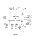
- FIG. 2( a ) is a schematic of the System Control of the present invention.
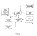
- FIG. 2( b ) is a schematic showing the interaction of the Heat Pump Manager with System Control of the present invention.
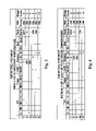
- FIG. 3 is a chart showing the decision process employed by System Control when it receives a call for heat from the indoor thermostat when the outdoor ambient temperature is high.
- FIG. 4 is a chart showing the decision process employed by System Control when it receives a call for heat from the indoor thermostat when the outdoor ambient temperature is medium.
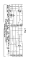
- FIG. 5 is a chart showing the decision process employed by System Control when it receives a call for heat from the indoor thermostat when the outdoor ambient temperature is low.
- FIG. 1 is a schematic of one embodiment of the heating and cooling system 10 of the present invention.
- the primary components of the system include a primary compressor 12 , a booster compressor 14 , a first condenser 16 , a second condenser 18 , a third condenser 20 , an economizer 22 , an evaporator 24 and a 4-way valve 26 .
- the primary compressor 12 is preferably a scroll-type two-speed compressor that may be operated at two discrete discharge pressure settings.
- the booster compressor 14 is preferably a single-speed compressor that may be operated at a single discharge pressure setting.
- the two compressors may be operated in series or the booster compressor 14 may be bypassed by opening booster compressor bypass valve 28 .
- a temperature sensor (HIT) monitors the temperature and a pressure sensor (HI) monitors the pressure of the refrigerant exiting the primary compressor 12 .
- the system is operated in one of three compressor output modes.
- the primary compressor 12 may be operated at low output.
- the primary compressor 12 may be operated at high output.
- both the booster compressor 14 and the primary compressor 12 may be operated with the primary compressor operating at high output.
- Compressed refrigerant from the compressors is directed to the third condenser 20 on the compressor side of system.
- the third condenser 20 the high-pressure condensed refrigerant transfers heat to water that is circulated by a water heater pump 30 to a water heater 32 .
- the water heater 32 utilizes the heat from the third condenser 20 to heat tap water for home or business use.
- the water heater 32 also includes a conventional heating element 34 that may also be used to heat the tap water.
- a temperature monitor (WH-RT) 116 senses the temperature of the water returning to the third condenser 20 from the water heater 32 . Because the third condenser 20 is located on the compressor side of the 4-way valve 26 , the third condenser may provide heat for water heating regardless of whether the system is in heating or cooling mode.
- WH-RT temperature monitor
- the refrigerant flows from the 4-way valve 26 to the first condenser 16 , which provides heat for a hydronic floor heating system 36 .
- a buffer tank pump 38 circulates water through the first condenser 16 and draws heat from the refrigerant to heat the water stored in a buffer tank 40 .
- a hydronic floor heating system pump 42 circulates the heated water from the buffer tank 40 to a hydronic loop 43 to heat the floor of an indoor space. Additional hydronic circuits with independent pumps or zone valves may also be provided to supply additional zones with hydronic heating from the buffer tank.
- a temperature monitor (WIT) 114 senses the temperature of the water in the buffer tank 40 .
- a temperature monitor (W-ST) 115 monitors the temperature of the water circulated through the first condenser 16 .
- the buffer tank 40 may not be required.
- the hydronic floor system water may be circulated in direct heat exchange relationship with the first condenser 16 to provide heat for the hydronic floor system without the need for a buffer tank.
- the WIT 114 and W-ST 115 temperature monitors are placed in the same hot water pipe.
- the refrigerant flows to a second condenser 18 , which provides air heating for an indoor space.
- a second condenser 18 which is the function it performs in heating mode
- the second condenser 18 operates as an evaporator in cooling mode.
- a blower 44 directs air over the second condenser 18 and draws heat from the refrigerant.
- the blower 44 is preferably a forced air ECM variable speed blower.
- a temperature monitor (ST) 111 senses the temperature of the air being heated by the second condenser 18 .
- the refrigerant flows to a receiver 50 and then to an economizer 22 .
- a portion of the refrigerant flow may be diverted through an expansion valve 46 and back to the economizer 22 in heat exchange relationship with original refrigerant flow.
- the diverted flow then flows from the economizer 22 to a mixing chamber 48 on the compression side of the system where the two phase refrigerant is mixed with superheated vapor leaving the booster compressor 14 prior to entering the primary compressor 12 .
- the remainder of the refrigerant flows to the evaporator 24 where a fan 51 blows air over the evaporator 24 to draw heat into the system.
- a fan 51 blows air over the evaporator 24 to draw heat into the system.
- the evaporator operates as a condenser in cooling mode.
- a temperature monitor (OT) 110 senses the outdoor temperature at the outdoor evaporator.
- a temperature monitor (ET) also senses the evaporating temperature of the refrigerant at the evaporator.
- the refrigerant flows through the 4-way valve 26 and back to the compression side of the system to repeat the cycle.
- An oil filtering and equalization system is also provided on the compression side of the system. Refrigerant leaving the compressors may have oil from the compressors entrained in the refrigerant which will degrade system performance. The oil is separated from the refrigerant by an oil separator 52 and oil filter 54 and returned to the suction side of the primary compressor 12 at point 56 to guarantee lubrication for the compressor.
- Oil may also tend to migrate from one compressor to the other depending on the operating conditions of the system.
- an oil equalization valve 58 is provided that is opened in certain conditions when the compressors are turned off to allow the oil level between the compressors to equalize.
- An accumulator 60 is also provided that regulates refrigerant flow to the compressors and protects the compressors from damage during startup.
- An auxiliary 120 ( FIG. 2( a )) or backup electric resistance heating system is also provided that may be used when the primary system components cannot provide adequate heating in extreme cold conditions or to remove load from the compressors under any operating conditions. If a remote utility Load Management Control receiver is implemented with the present system, as described in detail below, a heating system with a different energy source, such as a gas furnace, may also be provided so that the system may utilize this alternative energy heat source when shut down by the Load Management Control receiver.
- a heating system with a different energy source such as a gas furnace
- cooling mode only the primary compressor 12 is operated, and it may be operated at either high or low capacity.
- the direction of flow is reversed so that the compressed refrigerant flows in the opposite direction on the heat exchange side of the system.
- the compressed refrigerant flows from the 4-way valve 26 to the evaporator 24 (now operating as a condenser) where heat is released to the outdoors.
- the refrigerant then flows to the second condenser 18 (now operating as an evaporator) and the refrigerant draws heat from the indoor air space.
- the first condenser 16 is bypassed by opening valve 62 and closing valve 64 , and refrigerant flows from the second condenser 18 to the 4-way valve 26 and back to the compression side of the system to repeat the cycle.
- Defrost mode is similar to cooling mode, except that the first condenser 16 is not bypassed.
- the 4-way valve 26 is reversed and compressed refrigerant is circulated to the evaporator 24 to defrost the coil.
- the refrigerant then flows to the second condenser 18 , where the blower 44 is turned off, and then to the first condenser 16 .
- valve 62 is closed and valve 64 is opened.
- a temperature monitor (FT) senses the temperature of the refrigerant entering the first condenser 16 .
- the refrigerant draws heat from the water circulating to the hydronic floor heating buffer tank 40 .
- the refrigerant then flows through the 4-way valve 26 and back to the compression side of the system to repeat the cycle.
- the heat from the first condenser 16 is delivered to the evaporator 24 to defrost the coil.
- the system returns to heating mode.
- the heating and cooling system 10 of the present invention includes temperature sensors throughout the system.
- the system also includes sensors that can shut off electrical power to one or both of the compressors under certain conditions.
- a mechanical safety sensor (HP) 68 detects the pressure of the refrigerant leaving the primary compressor 12 and will shut off the compressors if the pressure exceeds a certain maximum.
- a mechanical disk thermostat (HT) 70 detects the temperature of the refrigerant leaving the primary compressor 12 and will shut off the compressor if the temperature exceeds a certain maximum.
- Additional pressure sensors are also located throughout the system and continuously monitor the pressure at various points in the system.
- the preferred embodiment of the system includes an indoor thermostat 112 (AIR-W, AIR-Y or AIR-G) that is a conventional, 4-wire, RWGY thermostat with a single-step setting for heat (AIR-W) and a single-step setting for cooling (AIR-Y). If set to heating, the indoor thermostat monitors the temperature of the indoor air space and calls for heating (AIR-W) at a temperature set at the thermostat. If set to cooling, the indoor thermostat 112 monitors the temperature of the indoor air space and calls for cooling (AIR-Y) at a temperature set at the thermostat.
- the hydronic floor heating system 36 includes a thermostat (LOOP-W) 113 ( FIG. 2( a )). This thermostat monitors the temperature of the hydronic floor heating system 36 and activates the pump 42 when the hydronic floor system requires heat. Upon request from the thermostat (LOOP-W) 113 , the pump 42 circulates heated water from the buffer tank 40 to the hydronic floor system 36 .
- LOOP-W thermostat
- FIG. 2( a ) is a schematic of the control system of the present invention.
- the primary inputs to the System Control 100 are received from an outdoor temperature monitor (OT) 110 , an air supply temperature monitor (ST) 111 , an indoor thermostat 112 , LOOP-W 113 , a temperature monitor for the water in the buffer tank (WIT) 114 , a temperature monitor for the water in first condenser (W-ST) 115 , a temperature monitor for the water in the third condenser (WH-RT) 116 , the utility load management 117 , the standby heat 121 and the Heat Pump Manager (HPM) 102 (collectively, “the inputs”).
- OT outdoor temperature monitor
- ST air supply temperature monitor
- ST indoor thermostat 112
- LOOP-W 113 a temperature monitor for the water in the buffer tank
- WIT buffer tank
- W-ST first condenser
- WH-RT temperature monitor for the water in the third condenser
- the utility load management 117
- the primary outputs from the system control 100 may be sent to the ECM Blower 44 , the buffer tank pump 38 , the water heater pump 30 , the HPM 102 , the standby heat 121 , the auxiliary electric 120 and the water heater 32 (collectively, “the outputs”).
- the System Control 100 receives inputs from the monitoring devices throughout the system, processes these signals, and makes a “request” to the Heat Pump Manager (HPM) 102 for an operational compressor sequence. As will be described in detail below, the System Control 100 is designed to maximize system efficiency. Through use of decision tables, the System Control 100 processes the inputs to control the outputs so that excess energy may be transferred within the system for maximum performance.
- HPM Heat Pump Manager
- FIG. 2( b ) is a schematic showing the interaction of the Heat Pump Manager 102 with System Control 100 of the present invention.
- This schematic shows the interconnectivity between the System Control 100 and the HPM 102 and the various components of the present invention.
- the various components include the System Control 100 , the Heat Pump Manager (HPM) 102 , the standby heat 121 , the utility load management 117 , the outdoor unit 25 , the water heater 32 , the relays 125 , the blower 44 , the limits 127 and the compressors 126 .
- the outdoor unit 25 includes evaporator 24 , fan 51 and temperature monitor ET (as shown in FIG. 1) .
- Relays 125 include the buffer tank pump 38 , the water heater pump 30 , the auxiliary heat 120 and the water heater 32 .
- the HPM 102 communicates with the compressors 127 , which includes the primary compressor 12 and the booster compressor 14 . Furthermore, the HPM 102 utilizes the Limits 127 , which includes high pressure (HP) 68 and high temperature (HT) 70 within the system. The HPM 102 monitors the Limits 127 to ensure safe operating conditions and system efficiency.
- FIG. 2( b ) also shows the HPM 102 interacting with the outdoor unit 25 . When the defrost mode is activated, the HPM 102 controls the outdoor unit 25 , the compressors 126 and the limits 127 as will be further described below.
- System Control 100 and HPM 102 are separate computers or controllers. However, the functions of System Control 100 and HPM 102 may be integrated into a single computer or controller and remain within the scope of the present invention.
- the HPM 102 may override or modify the operating parameters set by the System Control 100 based on additional calculations performed by the HPM 102 and/or preset operating limits for certain system components.
- the HPM 102 thus sets the “actual,” or real time, stage code for the system and prevents unsafe or less than optimal operating conditions.
- the system uses eight Stage Codes that correspond to certain operating configurations for the compressors:
- the system is activated when the indoor thermostat 112 calls for heating (AIR-W) or cooling (AIR-Y), or when the buffer tank 40 requires heating.
- the Indoor thermometer calls for heating (AIR-W)
- the System Control 100 determines a Request Stage Code and indoor air blower 44 speed based on the outdoor temperature (OT).
- OT outdoor temperature
- a symbol e.g., “OT” together with a reference number is used to designate the temperature monitor.
- the symbol designates the temperature readout on the corresponding temperature monitor.
- OT 110 designates the outdoor temperature monitor and “OT” alone designates the temperature readout from the outdoor temperature monitor.
- System Control 100 requests Stage Code 1 (primary compressor 12 on low) from the HPM 102 and sets the indoor air blower 44 speed to low. If the outdoor temperature (OT) is medium ( ⁇ 55° F. and >20° F.), System Control 100 requests Stage Code 2 (primary compressor 12 on high) and sets the indoor air blower 44 speed to medium. If the outdoor temperature (OT) is low ( ⁇ 20° F.), System Control 100 requests Stage Code 3 (primary compressor 12 on high and booster compressor 14 on) and sets the indoor air blower 44 speed to high. System Control 100 then controls the blower 44 , the buffer tank pump 38 , the water heater pump 30 and potentially the auxiliary heating elements according to the decision tables shown in FIGS. 3-5 .
- System Control 100 sets the indoor air blower speed and the output of the compressors, which in turn determine the BTU delivery into the indoor air space. Although the outdoor temperature determines the initial blower and compressor settings, System Control 100 may then alter these parameters, along with BTU delivery to the buffer tank 40 and the water heater 32 , to maximize indoor air comfort and system efficiency. If the indoor air thermostat (AIR-W) is not satisfied after a preset time, System Control 100 may increase the blower speed and increase the Request Stage Code to the HPM 102 for the compressors. If both the blower 44 and the compressors 126 are in highest output mode and the indoor air thermostat 112 remains unsatisfied, System Control 100 may add auxiliary heating to satisfy the indoor air thermostat 112 call for heat.
- AIR-W indoor air thermostat
- System Control 100 monitors the air supply temperature (ST) at the indoor blower 44 . If ST is either too low to heat the indoor air space or too high for efficient compressor operation, System Control 100 may either change the Request Stage Code for the compressors or activate or deactivate the buffer tank pump 38 and/or the water heater pump 30 .
- System Control 100 attempts to keep the buffer tank pump 38 and the water heater pump 30 running to utilize any excess energy within the system. Also, by diverting energy to the buffer tank 40 and the water heater 32 whenever possible, compressor run time is increased, which decreases the wear and tear on the compressors caused by frequent start ups. Thus, whenever ST appears to be sufficient to satisfy the call for heat, the buffer tank pump 38 and the water heater pump 30 are activated or kept running. However, if ST goes low, the buffer tank pump 38 and/or the water heater pump 30 may be deactivated so that sufficient energy is available for heating the indoor air space.
- FIGS. 3-5 The decision steps utilized by System Control 100 after receiving a call for heat from the indoor air thermostat 112 (AIR-W) are shown in FIGS. 3-5 .
- ST is the temperature of the air being heated by the second condenser 18 at the indoor air blower 44 .
- L, M, H are low, medium and high set points for the ST temperature, which are preferably set at 92° F., 96° F. and 102° F. respectively.
- the “ ⁇ ” and “+” signs refer to the ST temperature dropping below (“ ⁇ ”) or rising above (“+”) the associated set point.
- Timer is an internal timer in the System Control 100 that measures the length of time since the indoor thermostat 112 has called for heat, thus providing a measure of time since the indoor thermostat 112 has remained unsatisfied.
- MU 1 is a shorter timer, preferably 15 minutes, and MU 2 is a longer timer, preferably 45 minutes.
- W-ST is the temperature of the water circulated to the buffer tank 40 by the buffer tank pump 38 . If this temperature exceeds a certain set point, preferably 105° F., the system attempts to divert heat from the buffer tank 40 .
- “Blower” is the forced air ECM variable speed indoor air blower 44 .
- auxiliary heating system 120 is an auxiliary heating system 120 that may be activated if heating requirements cannot be met by the system.
- the auxiliary heating system 120 may be any type of alternative heating component or system including an electrical resistance heater, a gas furnace or other type of heating. Auxiliary heating may be provided at low (EL 1 ) or high (EL 2 ) output.
- Tank pump is the buffer tank pump 38 .
- the buffer tank pump 38 is activated whenever possible to divert energy to the buffer tank 40 , and also as a control mechanism to address high temperature and pressure conditions in the system.
- WH Pump is the water heater pump 30 .
- the water heater pump is nearly always set to “ON” whenever the system is running so that heat may be provided to the water heater 32 for water heating.
- the water heater pump 30 may be deactivated.
- Stage Code is the Stage Code requested by System Control 100 , which may be modified by the HPM 102 as will be described in detail below.
- the “+” symbol means that the system component is activated and the “ ⁇ ” symbol means that the system component is deactivated.
- “ON” or “OFF” means that the system component is already on or off, or, in some instances, is turned on or off in that decision step.
- the asterisk “*” symbol indicates a system parameter that is monitored and may trigger the activation or deactivation of a system component.
- “IF” indicates a system parameter that is monitored and must be satisfied to allow the activation or deactivation of a system component.
- System Control 100 when the System Control 100 receives a call for heat from the indoor air thermometer (AIR-W) and the outdoor temperature (OT) is high (>55° F.), System Control 100 activates the indoor air blower 44 on low speed and requests Stage Code 1 (primary compressor 12 on low) from the HPM 102 , as shown in Line 1 . System Control 100 then monitors the system parameters to determine if changes to the system should be made to increase the BTU's delivered to the indoor air space or to improve system performance and efficiency.
- AIR-W indoor air thermometer
- OT outdoor temperature
- System Control 100 activates the buffer tank pump 38 to divert energy to the buffer tank 40 .
- ST falls below the low temperature set point, meaning that energy is needed to heat the indoor air space
- the buffer tank pump 38 is terminated. If the temperature of the water being circulated to the buffer tank exceeds 105° F., as shown in Line 4 , the blower speed is increased to medium to divert energy to the indoor air space.
- the indoor blower is set to high to divert additional energy to the indoor air space. If the indoor thermostat 112 remains unsatisfied after 45 minutes (MU 2 ), as shown in Line 6 , System Control 100 sets the blower speed to high and requests Stage Code 2 (primary compressor 12 set to high) from the HPM 102 .
- System Control 100 when the System Control 100 receives a call for heat from the indoor air thermometer (AIR-W) and the outdoor temperature (OT) is medium ( ⁇ 55° F. and >20° F.), System Control 100 activates the indoor air blower 44 on medium speed and requests Stage Code 2 (primary compressor 12 on high) from the HPM 102 , as shown in Line 7 . Then, as shown in Line 8 , if the temperature of the air at the indoor air blower (ST) exceeds the medium set point, System Control 100 activates the buffer tank pump 38 to divert energy to the buffer tank 40 . As shown in Line 9 , if ST falls below the low temperature set point, the buffer tank pump 38 is terminated.
- AIR-W indoor air thermometer
- OT outdoor temperature
- Stage Code 2 primary compressor 12 on high
- System Control 100 sets the blower speed to high and requests Stage Code 3 (primary compressor 12 set to high and booster compressor 14 activated) from the HPM 102 .
- System Control 100 when the System Control 100 receives a call for heat from the indoor air thermometer (AIR-W) and the outdoor temperature (OT) is low ( ⁇ 20° F.), System Control 100 activates the indoor air blower 44 on high speed, requests Stage Code 3 (primary compressor 12 on high and booster compressor activated) from the HPM 102 and leaves the water heater pump 30 off, as shown in Line 12 . System Control 100 then steps down the table in progressive steps as needed.
- AIR-W indoor air thermometer
- OT outdoor temperature
- System Control 100 activates the water heater pump 30 to divert energy to the water heater 32 to provide heat for water heating. As shown in Line 14 , if ST then falls below the medium temperature set point, the water heater pump 30 is terminated. As shown in Line 15 , if ST exceeds the high set point, System Control 100 activates both the buffer tank pump 38 and the water heater pump 30 . As shown in Line 16 , if ST drops below the medium set point when both the buffer tank pump 38 and the water heater pump 30 are running, both are deactivated.
- the system may also be activated when the buffer tank 40 requires heating.
- the hydronic floor heating system 36 includes a thermostat (LOOP-W) 113 that activates the pump 42 and notifies System Control 100 when the hydronic loop 43 requires heat.
- System Control 100 then waits three minutes. This delay allows the water to circulate from the buffer tank 40 to the hydronic loop 43 before determining whether the buffer tank 40 requires heating. The delay also gives the system time to potentially divert excess energy to the buffer tank 40 under normal operation of the system, thereby avoiding premature, unnecessary and intermittent start up of the compressors. After three minutes, System Control 100 continuously monitors the temperature of the water in the buffer tank 40 through WIT 114 .
- System Control 100 checks whether AIR-W is ON, which would indicate that the indoor air space requires heating. If AIR-W is ON, indoor air heating takes precedence over hydronic floor heating and System Control 100 continues to follow the decision steps detailed above. If AIR-W is OFF after the delay, meaning that the indoor air space does not require heating, System Control 100 may then activate the buffer tank 38 to provide heat to the buffer tank 40 .
- the goal of the system is to utilize the third condenser 20 rather the element 34 to heat the water in the water heater 32 because the heat pump provides more efficient heating that the heating element of a conventional water heater.
- the water heater pump 30 runs under most conditions when the primary compressor 12 or both compressors are running.
- the element 34 is interrupted whenever possible so that the third condenser 20 , rather than the water heater element 34 , is providing energy to the water heater.
- the water heater pump 30 is interrupted or left off. As shown in FIG. 5 at line 12 , the water heater pump 30 is left off when the system is activated upon a call for heat at a low outdoor temperature. As shown in FIG. 5 at lines 14 and 16 , the water heater pump 30 is deactivated when the temperature of the air at the indoor air blower (ST) drops below the medium temperature set point. As shown in FIG. 5 at lines 18 and 19 , the water heater pump 30 is not run when the indoor air thermostat 112 is not satisfied after either the short (MU 1 ) or longer (MU 2 ) time period.
- ST indoor air blower
- the water heater pump 30 is also interrupted when the temperature of the water circulating to the water heater (WH-RT) exceeds a certain temperature (125°). (However, when Stage Code 4 is activated as explained below, the water heater pump 30 is activated despite the high temperature of WH-RT.)
- the element 34 provides heat for water heating whenever the system is not running. To achieve the goal of utilizing heat from the third condenser 20 rather than the element 34 whenever possible, the element 34 is interrupted whenever the system starts or stops. A timer is then started. At the expiration of the timer, the element 34 then is allowed to decide for itself based on its own thermometer whether to turn on and heat the water in the water heater 32 .
- the heat pump should provide sufficient energy to heat the water in the water heater 32 within this time period so that, at the expiration of the timer, the element 34 will not need to provide heating. However, if a significant amount of hot water is being used, the element 34 may provide additional heating at the expiration of the timer.
- a longer timer 120 minutes is started. This timer prevents the element 34 from activating at the end of a heat pump cycle when the system may be restarting within a short time period. If the system does not restart, however, heating control is returned to the element and the conventional water heater thermostat.
- the element deactivation timer at system shutdown should typically be longer than the element deactivation timer at system startup. At system startup, the system is providing heat to the water heater. The timer may be shorter so that the element can determine whether supplemental heating is required, such as, for example, when someone is draining the hot water and the heat pump cannot keep up.
- the inventor currently contemplates setting the shutdown timer at 120 minutes and the startup timer at 30 minutes, but these settings depend on the water heater tank size, household domestic hot water use and other factors.
- Element interrupts may also be incorporated based on the outside air temperature (OT).
- OT outside air temperature
- the heat pump system should provide sufficient heating for water in the water heater 32 under all system conditions so that element heating is never required.
- the system may require that energy be diverted from the water heater 32 to the indoor air space for to satisfy indoor air comfort requirements.
- element heating of the water for domestic use may be more frequently required.
- the element 34 is not interrupted and the element is free to cycle on its own internal thermostat.
- HPM 102 may override the system parameters set by System Control 100 and provide internal control of the system components and compressors. These overrides may occur to prevent unsafe operating conditions or to increase the operating efficiency of the system.
- Stage Code 4 activates the buffer tank pump 38 and the water heater pump 30 for thirty seconds if they are not already activated. Activation of these pumps draws energy from the system in an attempt to prevent the pressure and temperature from going over limit and utilizes this excess energy for the hydronic floor heating system 36 and/or the water heater 32 .
- Stage Code 4 operates as a safety control while simultaneously increasing the efficiency of the system.
- the HPM 102 constantly calculates a high side/low side (HI/LO) pressure ratio to further control the system.
- the HPM 102 reads the pressure transducer at the outlet of the primary compressor (HP).
- the HPM 102 monitors the evaporating temperature of the refrigerant at the evaporator (ET) at all times to ensure that the compressors are always running in an efficient mode. Based on input from ET, the HPM may override a stage code request from System Control that would place the system in an inefficient operating mode.
- ET evaporator
- the HPM 102 will decrease the Stage Code (converting from Stage Code 3 to 2, or from Stage Code 2 to 1) if the system generates a pressure (HI) greater than 500 psig or a temperature (HIT) greater than 220° at the outlet of the primary compressor.
- HI pressure
- HIT temperature
- the HPM 102 attempts to address a high pressure or high temperature condition by reducing the output of the compressors before taking more drastic steps.
- the HPM 102 performs a “soft hold,” which is an auto reset of the system. Under this condition, the entire system shuts down, resets and starts up again.
- the HPM 102 will also perform a soft hold if the primary compressor exceeds 30A during a heating cycle or if the amps of the primary compressor increase more than 30% in 10 seconds.
- a soft hold may also be initiated in defrost mode if the temperature (FT) of the refrigerant entering the first condenser 16 is below a predetermined point to prevent potential freeze-up during defrost.
- the system hardware may also perform a “hard hold,” or complete system shut down, if the system generates a pressure (HP) greater than 600 psig or a temperature (HT) greater than 250° F. at the outlet of the primary compressor.
- HPM 102 will also perform a hard hold if three soft hold restarts occur within 12 hours.
- the HPM 102 In addition to controlling the system compressors to maximize the efficiency and safety of the system, the HPM 102 also controls the economizer 22 to further optimize performance of the system.
- the HPM 102 precisely regulates the flow of refrigerant through the economizer 22 based on the temperature or pressure of the refrigerant leaving the primary compressor 12 .
- the HPM 102 opens the expansion valve 46 2% to provide a flow of refrigerant through the economizer.
- the HPM 102 opens the expansion valve 46 an additional 2%.
- a 22% injection flow is provided.
- the HPM 102 also reads the temperature at the primary compressor outlet (HIT) and, starting at 170°, opens the valve 46 diverting flow to the economizer 2% for every 3° increase in temperature. This causes, for example, an injection of 18% at 194° F. The actual injection is the larger of the two percentages that result from the HPM's calculations.
- HIT primary compressor outlet
- the system is activated when the indoor thermostat 112 calls for cooling.
- the booster compressor 14 is not used.
- the primary compressor 12 is used at low speed (Stage Code 5) or high speed (Stage Code 6) if additional cooling capacity is required.
- Stage Code 6 may be activated after a predetermined time, preferably 90 minutes, if Stage Code 5 fails to satisfy the thermostat (AIR-Y).
- the HPM 102 In cooling mode, all pressure and temperature calculations are disabled. However, the HPM 102 will convert from Stage Code 6 operation to Stage Code 5 operation if the system generates a pressure (HP) greater than 480 psig or a temperature (HT) greater than 200° F. at the outlet of the primary compressor. The HPM 102 will also perform a soft hold if the temperature at the outlet of the primary compressor (HIT) exceeds 230° F., the primary compressor 12 exceeds 30A during a heating cycle or the amps of the primary compressor increase more than 20% in 20 seconds. The safety settings for a hard hold also remain active.
- HP pressure
- HT temperature
- the HPM 102 may activate the defrost mode one of three ways. First, if the outside temperature (OT) has been 40° F. or less for 2 hours of cumulative system run time or 15° F. or less for 4 hours of cumulative system run time, the defrost cycle is activated. Second, the evaporator 24 includes a pressure differential switch that may activate the defrost cycle. Third, the defrost cycle may be manually activated. During a defrost cycle, the system disables all compressor, pressure and staging calculations and decisions.
- the compressors 12 and 14 and the outdoor fan 51 are turned off and the buffer tank pump 38 is activated.
- the 4-way valve 26 is reversed and the primary compressor 12 is activated.
- the refrigerant then flows through the first condenser 16 to transfer heat from the buffer tank 40 to the refrigerant that is cycled to the evaporator 24 to defrost the coil.
- the outdoor fan 51 is turned back on, the 4-way valve 26 is reversed and the buffer tank pump 38 is turned off or allowed to return to whatever mode it was in prior to the defrost cycle.
- the present invention is also compatible and easily integrated with utility Load Management Control.
- Load Management Control or LMC, allows a utility company to remotely and temporarily shut down certain users' heating and cooling systems at times when the utility is experiencing peak loads. This flexibility in addressing peak load conditions is a great advantage to utility companies.
- a utility company In exchange for the right and ability to remotely shut down a user's heating and cooling system, a utility company will typically provide reduced electricity rates, which is of course an advantage to the consumer.
- the system includes a remote receiver or communication device provided by the utility company.
- the utility company may communicate with the remote receiver via a telephone line, radio waves, the internet or other means.
- the remote receiver is integrated with System Control 100 so that, when the remote receiver receives a signal from the utility company, the remote receiver instructs System Control 100 to place the heating and cooling system on standby. System control 100 then shuts down the system (including any auxiliary electrical heating) for a set period of time, or until a restart signal is received from the utility company through the remote receiver.
- An auxiliary heating system 120 with a different energy source is typically provided to provide heat when Load Management Control initiates a system shut down in cold weather conditions.
- This backup heating source is an integral part of the system and controlled by the System Control 100 . By providing this control, the system can easily transition to the backup heating source when a shut down command is received, and also easily transition back to the main heating system when the shut down condition terminates.
- the present system is designed to provide three outputs-forced air heating and cooling for an indoor air space, water heating for a hydronic heating system and water heating for a conventional tap water heater.
- the novel system configuration and control diverts energy among these three outputs to maximize comfort, increase system efficiency, control high system load conditions, maximize compressor run times and utilize excess system energy.
- the preferred embodiment of the present invention utilizes three outputs to achieve these goals, these goals may also be achieved with only two of the three outputs.
- alternative embodiments of the present invention include systems with forced air heating and cooling combined with hydronic floor heating, forced air heating and cooling combined with tap water heating and hydronic floor heating combined with tap water heating.
Abstract
A heat pump system is disclosed that utilizes one or two compressors and multiple heat exchangers to provide forced air heating, radiant heating and/or water heating for an interior space. A controller directs energy to these multiple system outputs to provide maximum comfort, effectively utilize any excess energy, address fluctuations in energy output, prevent unsafe operating conditions and avoid intermittent compressor operation. The system may provide energy for a water heater in both heating and cooling mode, and control operation of the water heater to utilize system energy whenever possible and avoid use of a conventional water heater heating element. Load Management Control is also provided so that the system may be shut down remotely by a utility company.
Description
- This application is a Continuation-in-Part of Application Serial No. US 2005/0252226 A1, entitled “Heating/Cooling System” and filed May 11, 2005, the contents of which are incorporated herein by reference.
- The present invention relates generally to heating and cooling systems and more specifically to a heating and cooling system with multiple compressors, multiple heat outputs and the control system for managing the system.
- Heat pump systems have found widespread application for heating and cooling homes and businesses. Because heat pump systems utilize the same primary components for both heating and cooling, they eliminate the need for separate heating and cooling systems and are therefore economical to install and use. Heat pump systems are also highly efficient, resulting in decreased energy costs to the consumer. As a result, the demand for heat pump systems in residential and business applications has continued to grow in recent years.
- The use of conventional heat pump systems in colder climates, however, presents significant challenges. In heating mode, a heat pump system draws heat energy from the outdoor air to heat an indoor space. Even at low ambient temperatures, heat may be drawn from the outdoor environment by evaporating refrigerant in an outdoor evaporator. The evaporated refrigerant is then compressed by one or more compressors and then cycled to an indoor condenser where the energy of the compressed refrigerant is released to the indoor space. The refrigerant is then cycled back to the outdoor evaporator to repeat the cycle.
- At very low temperatures, however, it becomes increasingly difficult to draw heat from the outdoor environment. In addition, at very low temperatures, the outdoor heat exchange coil is very susceptible to frost build up, which limits air flow across the coil. As a result, the performance and efficiency of heat pump systems decreases drastically at very low ambient temperatures when heating capacity is most needed. To address this issue, increased compressor capacity is required for heat pump systems installed in colder climates. Single compressor systems have been utilized that can provide heating at low to moderate ambient temperatures, but such systems typically demonstrate decreased efficiency and performance at higher temperatures. Such systems must cycle on and off frequently at higher ambient temperatures, resulting in a reduced lifespan for the compressor and decreased system efficiency. Variable speed compressors have been used to address this problem, but these types of compressors are expensive and lead to increased installation costs for the system.
- Multiple compressor systems have been proposed to adapt the heat pump concept for use in colder climates. These systems utilize a primary compressor for heating and cooling in moderate temperatures, and also include a booster compressor to provide increased capacity at very low temperatures. An economizer, which utilizes a diverted portion of the refrigerant flow to subcool the refrigerant flowing to the evaporator, may also be used to provide increased heating capacity at very cold temperatures. Systems utilizing multiple compressors and an economizer are disclosed, for example, in U.S. Pat. Nos. 5,927,088, 6,276,148 and 6,931,871 issued to Shaw. Although the systems disclosed in these patents address the need to provide increased heating capacity at very cold temperatures, those of skill in the art have continued to seek sophisticated methods that effectively control the multiple compressors to maximize system efficiency and utilize the full output potential of the compressors.
- In particular, prior art systems have controlled multiple compressors based on limited system inputs. For example, the '148 and '871 patents issued to Shaw disclose dual compressor systems that select compressor output in response to decreases and/or increases in outdoor ambient temperature. The '871 patent issued to Shaw discloses a system that selects compressor output in response to a multi-step indoor thermostat and the system low side pressure, which pressure is commensurate with outdoor ambient air temperature during all heating cycle modes of operation. These control methodologies, however, may lead to frequent calls for changes in compressor output, which will cause one or both of the compressors to cycle on and off. Although important to prevent unsafe and inefficient compressor operation, a system control that more effectively manages when compressors are turned on and off is desirable. Such a system may lead to increased compressor run times in a consistent output condition, which increases the life of the compressors and overall system efficiency.
- Prior art systems have disclosed the use of multiple compressors to provide heat for an indoor forced air heat exchanger. With multiple compressors, however, additional heating capacity is present that may also be utilized for an additional indoor heating system such as a hydronic floor system. The heat pump system may also provide energy for a tap water heater. With these additional heating components integrated into the heat pump system, the potential output of the compressors may be more fully realized, providing further justification for the cost of the system. Further, if properly configured and controlled, these additional heating components may be used to absorb excess energy produced by the compressors to address and limit high pressure and temperature conditions. Also, with multiple heating components receiving energy input from the compressors, compressor run time can be increased. With the compressors cycling on and off less frequently, the life span and efficiency of the compressors is increased.
- Despite the increased capacity provided by multiple compressors, heat pump systems installed in very cold climates may require some form of back up heating to address the very coldest conditions. Prior art systems, however, have not effectively integrated control of the back up heating system with the control of the heat pump system. As a result, the back up heating system, which performs at lower efficiency, is over utilized as compared to the heat pump system, leading to increased energy costs. If the two systems are effectively integrated and controlled, the higher efficiency of the heat pump system may be more fully utilized even during the coldest months of the year.
- Finally, those of skill in the art have sought a heat pump system that effectively integrates utility Load Management Control. Load Management Control, or LMC, allows a utility company to remotely and temporarily shut down certain users' heating and cooling systems at times when the utility is experiencing peak loads. Because this capability is desirable for utility companies, energy consumers that implement this feature may receive decreased energy rates, tax incentives or other consideration. To implement LMC, an auxiliary heating system with a different energy source, such as a gas furnace, is typically required to provide heat when the utility initiates a system shut down in cold weather conditions. Control of this alternative heating source is preferably integrated with control of the heat pump system so that the system effectively and efficiently transitions to the alternative heat source when a shut down command is received, and also easily transitions back to the main heating system when the shut down condition terminates.
- Accordingly, an object of the present invention is to provide a heat pump system for use in colder climates that is economical to install and use.
- An additional object of the present invention is to provide a heat pump system with multiple compressors that effectively controls the compressors to maximize system efficiency and utilize the full output potential of the compressors.
- A further object of the present invention is to provide a heat pump system with multiple heat outputs including a forced air heater, a hydronic floor heating system and/or a water heater.
- Yet another object of the present invention is to provide a heat pump control system that may easily and effectively divert compressor energy to multiple heat outputs to fully utilize the output of the compressors, address high pressure and temperature conditions, increase compressor run times, decrease compressor cycling and maximize the overall efficiency of the system.
- Still another object of the present invention is to provide a heat pump control system that effectively integrates a back up heating system for use in the very coldest conditions.
- A still further object of the present invention is to provide a heat pump system that effectively integrates utility Load Management Control.
- Additionally, an object of the present invention is to provide a heat pump system that may effectively defrost the outdoor coil.
- Finally, an object of the present invention is to provide a heat pump system that provides energy for heating tap water when the system is in use for either heating or cooling, and also minimizes the use of the water heater element under all conditions.
- The preferred embodiment of the present invention provides increased heating capacity through the use of a primary compressor, a booster compressor and an economizer. The system effectively utilizes this heating capacity with three heat exchangers that provide 1) indoor air heating or cooling, 2) hydronic floor heating and 3) tap water heating. In addition to providing additional heating capabilities, the heat energy generated by the system may be easily diverted between the indoor air heating system, the hydronic floor heating system and the water heater to provide maximum comfort and energy utilization, store energy for later use and address fluctuations in the energy output of the system.
- The system utilizes a novel control system that: 1) prevents unsafe operating parameters; 2) ensures comfortable indoor heating and cooling; 3) utilizes any excess energy present in the system, or stores that energy for later use, by diverting the energy to the hydronic floor heating system and/or the water heater and 4) provides for long run times of the system at optimal conditions to prevent unnecessary and intermittent start up of the compressors.
- The system further includes a backup heating source that is effectively integrated and controlled by the system. Load Management Control is also provided so that the system may be shut down remotely by a utility company.
-
FIG. 1 is a schematic of the preferred embodiment of the heating and cooling system of the present invention. -
FIG. 2( a) is a schematic of the System Control of the present invention. -
FIG. 2( b) is a schematic showing the interaction of the Heat Pump Manager with System Control of the present invention. -
FIG. 3 is a chart showing the decision process employed by System Control when it receives a call for heat from the indoor thermostat when the outdoor ambient temperature is high. -
FIG. 4 is a chart showing the decision process employed by System Control when it receives a call for heat from the indoor thermostat when the outdoor ambient temperature is medium. -
FIG. 5 is a chart showing the decision process employed by System Control when it receives a call for heat from the indoor thermostat when the outdoor ambient temperature is low. -
FIG. 1 is a schematic of one embodiment of the heating andcooling system 10 of the present invention. The primary components of the system include aprimary compressor 12, abooster compressor 14, afirst condenser 16, asecond condenser 18, athird condenser 20, aneconomizer 22, anevaporator 24 and a 4-way valve 26. - The
primary compressor 12 is preferably a scroll-type two-speed compressor that may be operated at two discrete discharge pressure settings. Thebooster compressor 14 is preferably a single-speed compressor that may be operated at a single discharge pressure setting. The two compressors may be operated in series or thebooster compressor 14 may be bypassed by opening boostercompressor bypass valve 28. A temperature sensor (HIT) monitors the temperature and a pressure sensor (HI) monitors the pressure of the refrigerant exiting theprimary compressor 12. - In the preferred embodiment of the present invention, and depending upon the heating and cooling demands on the system, the system is operated in one of three compressor output modes. First, the
primary compressor 12 may be operated at low output. Second, theprimary compressor 12 may be operated at high output. Third, both thebooster compressor 14 and theprimary compressor 12 may be operated with the primary compressor operating at high output. These compressor output modes and the system controls that determine which mode to utilize at any given time will be described in detail below. - Compressed refrigerant from the compressors is directed to the
third condenser 20 on the compressor side of system. In thethird condenser 20, the high-pressure condensed refrigerant transfers heat to water that is circulated by awater heater pump 30 to awater heater 32. Thewater heater 32 utilizes the heat from thethird condenser 20 to heat tap water for home or business use. Thewater heater 32 also includes aconventional heating element 34 that may also be used to heat the tap water. A temperature monitor (WH-RT) 116 senses the temperature of the water returning to thethird condenser 20 from thewater heater 32. Because thethird condenser 20 is located on the compressor side of the 4-way valve 26, the third condenser may provide heat for water heating regardless of whether the system is in heating or cooling mode. - In heating mode, the refrigerant flows from the 4-
way valve 26 to thefirst condenser 16, which provides heat for a hydronicfloor heating system 36. Abuffer tank pump 38 circulates water through thefirst condenser 16 and draws heat from the refrigerant to heat the water stored in abuffer tank 40. A hydronic floorheating system pump 42 circulates the heated water from thebuffer tank 40 to a hydronic loop 43 to heat the floor of an indoor space. Additional hydronic circuits with independent pumps or zone valves may also be provided to supply additional zones with hydronic heating from the buffer tank. A temperature monitor (WIT) 114 senses the temperature of the water in thebuffer tank 40. A temperature monitor (W-ST) 115 monitors the temperature of the water circulated through thefirst condenser 16. - In certain installation configurations where the hydronic floor has sufficient capacity (minimum radiant floor size of at least 35,000 Btu/hr, or approximately 1800 sq. ft.), the
buffer tank 40 may not be required. In these installations, the hydronic floor system water may be circulated in direct heat exchange relationship with thefirst condenser 16 to provide heat for the hydronic floor system without the need for a buffer tank. In this arrangement, theWIT 114 and W-ST 115 temperature monitors are placed in the same hot water pipe. - After the first condenser, the refrigerant flows to a
second condenser 18, which provides air heating for an indoor space. Although referred to herein as a “condenser,” which is the function it performs in heating mode, thesecond condenser 18 operates as an evaporator in cooling mode. Ablower 44 directs air over thesecond condenser 18 and draws heat from the refrigerant. Theblower 44 is preferably a forced air ECM variable speed blower. A temperature monitor (ST) 111 senses the temperature of the air being heated by thesecond condenser 18. - After the
second condenser 18, the refrigerant flows to areceiver 50 and then to aneconomizer 22. After theeconomizer 22, a portion of the refrigerant flow may be diverted through anexpansion valve 46 and back to theeconomizer 22 in heat exchange relationship with original refrigerant flow. The diverted flow then flows from theeconomizer 22 to a mixingchamber 48 on the compression side of the system where the two phase refrigerant is mixed with superheated vapor leaving thebooster compressor 14 prior to entering theprimary compressor 12. - The remainder of the refrigerant flows to the
evaporator 24 where a fan 51 blows air over theevaporator 24 to draw heat into the system. Although referred to herein as an “evaporator,” which is the function it performs in heating mode, the evaporator operates as a condenser in cooling mode. A temperature monitor (OT) 110 senses the outdoor temperature at the outdoor evaporator. A temperature monitor (ET) also senses the evaporating temperature of the refrigerant at the evaporator. - After the
evaporator 24, the refrigerant flows through the 4-way valve 26 and back to the compression side of the system to repeat the cycle. An oil filtering and equalization system is also provided on the compression side of the system. Refrigerant leaving the compressors may have oil from the compressors entrained in the refrigerant which will degrade system performance. The oil is separated from the refrigerant by anoil separator 52 andoil filter 54 and returned to the suction side of theprimary compressor 12 at point 56 to guarantee lubrication for the compressor. - Oil may also tend to migrate from one compressor to the other depending on the operating conditions of the system. To address oil migration, an
oil equalization valve 58 is provided that is opened in certain conditions when the compressors are turned off to allow the oil level between the compressors to equalize. Anaccumulator 60 is also provided that regulates refrigerant flow to the compressors and protects the compressors from damage during startup. - An auxiliary 120 (
FIG. 2( a)) or backup electric resistance heating system is also provided that may be used when the primary system components cannot provide adequate heating in extreme cold conditions or to remove load from the compressors under any operating conditions. If a remote utility Load Management Control receiver is implemented with the present system, as described in detail below, a heating system with a different energy source, such as a gas furnace, may also be provided so that the system may utilize this alternative energy heat source when shut down by the Load Management Control receiver. - In cooling mode, only the
primary compressor 12 is operated, and it may be operated at either high or low capacity. At the 4-way valve 26, the direction of flow is reversed so that the compressed refrigerant flows in the opposite direction on the heat exchange side of the system. Thus, the compressed refrigerant flows from the 4-way valve 26 to the evaporator 24 (now operating as a condenser) where heat is released to the outdoors. The refrigerant then flows to the second condenser 18 (now operating as an evaporator) and the refrigerant draws heat from the indoor air space. In cooling mode, thefirst condenser 16 is bypassed by openingvalve 62 and closingvalve 64, and refrigerant flows from thesecond condenser 18 to the 4-way valve 26 and back to the compression side of the system to repeat the cycle. - Defrost mode is similar to cooling mode, except that the
first condenser 16 is not bypassed. When the system is in heating mode and the outdoor evaporator requires defrosting, the 4-way valve 26 is reversed and compressed refrigerant is circulated to theevaporator 24 to defrost the coil. The refrigerant then flows to thesecond condenser 18, where theblower 44 is turned off, and then to thefirst condenser 16. To direct the flow of the refrigerant to thefirst condenser 16,valve 62 is closed andvalve 64 is opened. A temperature monitor (FT) senses the temperature of the refrigerant entering thefirst condenser 16. At thefirst condenser 16, the refrigerant draws heat from the water circulating to the hydronic floorheating buffer tank 40. The refrigerant then flows through the 4-way valve 26 and back to the compression side of the system to repeat the cycle. Thus, the heat from thefirst condenser 16 is delivered to theevaporator 24 to defrost the coil. When defrosting is completed, the system returns to heating mode. - As described above, the heating and
cooling system 10 of the present invention includes temperature sensors throughout the system. The system also includes sensors that can shut off electrical power to one or both of the compressors under certain conditions. A mechanical safety sensor (HP) 68 detects the pressure of the refrigerant leaving theprimary compressor 12 and will shut off the compressors if the pressure exceeds a certain maximum. Similarly, a mechanical disk thermostat (HT) 70 detects the temperature of the refrigerant leaving theprimary compressor 12 and will shut off the compressor if the temperature exceeds a certain maximum. Additional pressure sensors are also located throughout the system and continuously monitor the pressure at various points in the system. - The preferred embodiment of the system includes an indoor thermostat 112 (AIR-W, AIR-Y or AIR-G) that is a conventional, 4-wire, RWGY thermostat with a single-step setting for heat (AIR-W) and a single-step setting for cooling (AIR-Y). If set to heating, the indoor thermostat monitors the temperature of the indoor air space and calls for heating (AIR-W) at a temperature set at the thermostat. If set to cooling, the
indoor thermostat 112 monitors the temperature of the indoor air space and calls for cooling (AIR-Y) at a temperature set at the thermostat. - The hydronic
floor heating system 36 includes a thermostat (LOOP-W) 113 (FIG. 2( a)). This thermostat monitors the temperature of the hydronicfloor heating system 36 and activates thepump 42 when the hydronic floor system requires heat. Upon request from the thermostat (LOOP-W) 113, thepump 42 circulates heated water from thebuffer tank 40 to thehydronic floor system 36. -
FIG. 2( a) is a schematic of the control system of the present invention. The primary inputs to theSystem Control 100 are received from an outdoor temperature monitor (OT) 110, an air supply temperature monitor (ST) 111, anindoor thermostat 112, LOOP-W 113, a temperature monitor for the water in the buffer tank (WIT) 114, a temperature monitor for the water in first condenser (W-ST) 115, a temperature monitor for the water in the third condenser (WH-RT) 116, theutility load management 117, thestandby heat 121 and the Heat Pump Manager (HPM) 102 (collectively, “the inputs”). The primary outputs from thesystem control 100 may be sent to theECM Blower 44, thebuffer tank pump 38, thewater heater pump 30, theHPM 102, thestandby heat 121, theauxiliary electric 120 and the water heater 32 (collectively, “the outputs”). - The
System Control 100 receives inputs from the monitoring devices throughout the system, processes these signals, and makes a “request” to the Heat Pump Manager (HPM) 102 for an operational compressor sequence. As will be described in detail below, theSystem Control 100 is designed to maximize system efficiency. Through use of decision tables, theSystem Control 100 processes the inputs to control the outputs so that excess energy may be transferred within the system for maximum performance. -
FIG. 2( b) is a schematic showing the interaction of theHeat Pump Manager 102 withSystem Control 100 of the present invention. This schematic shows the interconnectivity between theSystem Control 100 and theHPM 102 and the various components of the present invention. The various components include theSystem Control 100, the Heat Pump Manager (HPM) 102, thestandby heat 121, theutility load management 117, theoutdoor unit 25, thewater heater 32, therelays 125, theblower 44, thelimits 127 and thecompressors 126. Theoutdoor unit 25 includesevaporator 24, fan 51 and temperature monitor ET (as shown inFIG. 1) .Relays 125 include thebuffer tank pump 38, thewater heater pump 30, theauxiliary heat 120 and thewater heater 32. - As shown in
FIG. 2( b), theHPM 102 communicates with thecompressors 127, which includes theprimary compressor 12 and thebooster compressor 14. Furthermore, theHPM 102 utilizes theLimits 127, which includes high pressure (HP) 68 and high temperature (HT) 70 within the system. TheHPM 102 monitors theLimits 127 to ensure safe operating conditions and system efficiency.FIG. 2( b) also shows theHPM 102 interacting with theoutdoor unit 25. When the defrost mode is activated, theHPM 102 controls theoutdoor unit 25, thecompressors 126 and thelimits 127 as will be further described below. - In the preferred embodiment of the present invention,
System Control 100 andHPM 102 are separate computers or controllers. However, the functions ofSystem Control 100 andHPM 102 may be integrated into a single computer or controller and remain within the scope of the present invention. - The
HPM 102 may override or modify the operating parameters set by theSystem Control 100 based on additional calculations performed by theHPM 102 and/or preset operating limits for certain system components. TheHPM 102 thus sets the “actual,” or real time, stage code for the system and prevents unsafe or less than optimal operating conditions. - The system uses eight Stage Codes that correspond to certain operating configurations for the compressors:
-
0 System is off 1 Heat - primary compressor on low 2 Heat - primary compressor on high 3 Heat - primary compressor on high, booster compressor on 4 Add Load capacity 5 Cool - primary compressor on low 6 Cool - primary compressor on high 7 System hold - safety or performance interrupt - The system is activated when the
indoor thermostat 112 calls for heating (AIR-W) or cooling (AIR-Y), or when thebuffer tank 40 requires heating. When the indoor thermometer calls for heating (AIR-W), theSystem Control 100 determines a Request Stage Code andindoor air blower 44 speed based on the outdoor temperature (OT). In the figures, a symbol (e.g., “OT”) together with a reference number is used to designate the temperature monitor. However, when the symbol alone is used, the symbol designates the temperature readout on the corresponding temperature monitor. Thus, for example,OT 110 designates the outdoor temperature monitor and “OT” alone designates the temperature readout from the outdoor temperature monitor. - If the outdoor temperature (OT) is high (>500),
System Control 100 requests Stage Code 1 (primary compressor 12 on low) from theHPM 102 and sets theindoor air blower 44 speed to low. If the outdoor temperature (OT) is medium (<55° F. and >20° F.),System Control 100 requests Stage Code 2 (primary compressor 12 on high) and sets theindoor air blower 44 speed to medium. If the outdoor temperature (OT) is low (<20° F.),System Control 100 requests Stage Code 3 (primary compressor 12 on high andbooster compressor 14 on) and sets theindoor air blower 44 speed to high.System Control 100 then controls theblower 44, thebuffer tank pump 38, thewater heater pump 30 and potentially the auxiliary heating elements according to the decision tables shown inFIGS. 3-5 . - Thus, based on the outdoor temperature,
System Control 100 sets the indoor air blower speed and the output of the compressors, which in turn determine the BTU delivery into the indoor air space. Although the outdoor temperature determines the initial blower and compressor settings,System Control 100 may then alter these parameters, along with BTU delivery to thebuffer tank 40 and thewater heater 32, to maximize indoor air comfort and system efficiency. If the indoor air thermostat (AIR-W) is not satisfied after a preset time,System Control 100 may increase the blower speed and increase the Request Stage Code to theHPM 102 for the compressors. If both theblower 44 and thecompressors 126 are in highest output mode and theindoor air thermostat 112 remains unsatisfied,System Control 100 may add auxiliary heating to satisfy theindoor air thermostat 112 call for heat. - To maximize system efficiency,
System Control 100 monitors the air supply temperature (ST) at theindoor blower 44. If ST is either too low to heat the indoor air space or too high for efficient compressor operation,System Control 100 may either change the Request Stage Code for the compressors or activate or deactivate thebuffer tank pump 38 and/or thewater heater pump 30. - For best system efficiency,
System Control 100 attempts to keep thebuffer tank pump 38 and thewater heater pump 30 running to utilize any excess energy within the system. Also, by diverting energy to thebuffer tank 40 and thewater heater 32 whenever possible, compressor run time is increased, which decreases the wear and tear on the compressors caused by frequent start ups. Thus, whenever ST appears to be sufficient to satisfy the call for heat, thebuffer tank pump 38 and thewater heater pump 30 are activated or kept running. However, if ST goes low, thebuffer tank pump 38 and/or thewater heater pump 30 may be deactivated so that sufficient energy is available for heating the indoor air space. - The decision steps utilized by
System Control 100 after receiving a call for heat from the indoor air thermostat 112 (AIR-W) are shown inFIGS. 3-5 . Within these tables, “ST” is the temperature of the air being heated by thesecond condenser 18 at theindoor air blower 44. In the ST columns, L, M, H are low, medium and high set points for the ST temperature, which are preferably set at 92° F., 96° F. and 102° F. respectively. The “−” and “+” signs refer to the ST temperature dropping below (“−”) or rising above (“+”) the associated set point. - “Timer” is an internal timer in the
System Control 100 that measures the length of time since theindoor thermostat 112 has called for heat, thus providing a measure of time since theindoor thermostat 112 has remained unsatisfied. MU1 is a shorter timer, preferably 15 minutes, and MU2 is a longer timer, preferably 45 minutes. - “W-ST” is the temperature of the water circulated to the
buffer tank 40 by thebuffer tank pump 38. If this temperature exceeds a certain set point, preferably 105° F., the system attempts to divert heat from thebuffer tank 40. - “Blower” is the forced air ECM variable speed
indoor air blower 44. The air blower speed (L, M or H), which is set bySystem Control 100, determines BTU delivery into the indoor air space (BTU=1.08×CFM×temperature differential). - “Aux” is an
auxiliary heating system 120 that may be activated if heating requirements cannot be met by the system. Theauxiliary heating system 120 may be any type of alternative heating component or system including an electrical resistance heater, a gas furnace or other type of heating. Auxiliary heating may be provided at low (EL1) or high (EL2) output. - “Tank pump” is the
buffer tank pump 38. Thebuffer tank pump 38 is activated whenever possible to divert energy to thebuffer tank 40, and also as a control mechanism to address high temperature and pressure conditions in the system. - “WH Pump” is the
water heater pump 30. As explained below, the water heater pump is nearly always set to “ON” whenever the system is running so that heat may be provided to thewater heater 32 for water heating. However, when additional heat is needed to heat the indoor air space, or if the temperature water circulated to thewater heater 32 exceeds a certain temperature, preferably 135° F., thewater heater pump 30 may be deactivated. - “Stage Code” is the Stage Code requested by
System Control 100, which may be modified by theHPM 102 as will be described in detail below. - Within
FIGS. 3-5 , the “+” symbol means that the system component is activated and the “−” symbol means that the system component is deactivated. “ON” or “OFF” means that the system component is already on or off, or, in some instances, is turned on or off in that decision step. The asterisk “*” symbol indicates a system parameter that is monitored and may trigger the activation or deactivation of a system component. “IF” indicates a system parameter that is monitored and must be satisfied to allow the activation or deactivation of a system component. After activating or deactivating a system component as shown inFIGS. 3-5 ,System Control 100 waits two minutes before making further system changes as provided in the tables. - Referring to
FIG. 3 , when theSystem Control 100 receives a call for heat from the indoor air thermometer (AIR-W) and the outdoor temperature (OT) is high (>55° F.),System Control 100 activates theindoor air blower 44 on low speed and requests Stage Code 1 (primary compressor 12 on low) from theHPM 102, as shown inLine 1.System Control 100 then monitors the system parameters to determine if changes to the system should be made to increase the BTU's delivered to the indoor air space or to improve system performance and efficiency. - As shown in
Line 2 ofFIG. 3 , if the temperature of the air at the indoor air blower (ST) exceeds the medium set point,System Control 100 activates thebuffer tank pump 38 to divert energy to thebuffer tank 40. As shown inLine 3, if ST falls below the low temperature set point, meaning that energy is needed to heat the indoor air space, thebuffer tank pump 38 is terminated. If the temperature of the water being circulated to the buffer tank exceeds 105° F., as shown inLine 4, the blower speed is increased to medium to divert energy to the indoor air space. If ST exceeds the high temperature set point or the water being circulated to the buffer tank exceeds 105° F., as shown inLine 5, the indoor blower is set to high to divert additional energy to the indoor air space. If theindoor thermostat 112 remains unsatisfied after 45 minutes (MU2), as shown inLine 6,System Control 100 sets the blower speed to high and requests Stage Code 2 (primary compressor 12 set to high) from theHPM 102. - Referring to
FIG. 4 , when theSystem Control 100 receives a call for heat from the indoor air thermometer (AIR-W) and the outdoor temperature (OT) is medium (<55° F. and >20° F.),System Control 100 activates theindoor air blower 44 on medium speed and requests Stage Code 2 (primary compressor 12 on high) from theHPM 102, as shown inLine 7. Then, as shown inLine 8, if the temperature of the air at the indoor air blower (ST) exceeds the medium set point,System Control 100 activates thebuffer tank pump 38 to divert energy to thebuffer tank 40. As shown inLine 9, if ST falls below the low temperature set point, thebuffer tank pump 38 is terminated. If the temperature of the water being circulated to thebuffer tank 40 exceeds 105° F., as shown inLine 10, the blower speed is increased to high to divert energy to the indoor air space. If theindoor thermostat 112 remains unsatisfied after 45 minutes (MU2), as shown inLine 11,System Control 100 sets the blower speed to high and requests Stage Code 3 (primary compressor 12 set to high andbooster compressor 14 activated) from theHPM 102. - Referring to
FIG. 5 , when theSystem Control 100 receives a call for heat from the indoor air thermometer (AIR-W) and the outdoor temperature (OT) is low (<20° F.),System Control 100 activates theindoor air blower 44 on high speed, requests Stage Code 3 (primary compressor 12 on high and booster compressor activated) from theHPM 102 and leaves thewater heater pump 30 off, as shown inLine 12.System Control 100 then steps down the table in progressive steps as needed. - As shown in
Line 13, if the temperature of the air at the indoor air blower (ST) exceeds the high set point,System Control 100 activates thewater heater pump 30 to divert energy to thewater heater 32 to provide heat for water heating. As shown inLine 14, if ST then falls below the medium temperature set point, thewater heater pump 30 is terminated. As shown inLine 15, if ST exceeds the high set point,System Control 100 activates both thebuffer tank pump 38 and thewater heater pump 30. As shown inLine 16, if ST drops below the medium set point when both thebuffer tank pump 38 and thewater heater pump 30 are running, both are deactivated. Referring toLine 17, if the temperature of the water being circulated to thebuffer tank 40 exceeds 105° F., thebuffer tank pump 38 and thewater heater pump 30 are activated. Referring toLine 18, if the indoor thermostat remains unsatisfied after 15 minutes (MU1) with the ST temperature below the high set point, auxiliary heating is activated at low output and thebuffer tank pump 38 is activated. Referring toLine 19, if the addition of the low output auxiliary heating fails to satisfy theindoor thermostat 112 after 45 minutes (MU2), high output auxiliary heating is activated and thebuffer tank pump 38 is deactivated. Finally, as shown inLine 20, if the ST temperature exceeds the high set point, both thebuffer tank pump 38 and thewater heater pump 30 are activated. - The system may also be activated when the
buffer tank 40 requires heating. As noted above, the hydronicfloor heating system 36 includes a thermostat (LOOP-W) 113 that activates thepump 42 and notifiesSystem Control 100 when the hydronic loop 43 requires heat.System Control 100 then waits three minutes. This delay allows the water to circulate from thebuffer tank 40 to the hydronic loop 43 before determining whether thebuffer tank 40 requires heating. The delay also gives the system time to potentially divert excess energy to thebuffer tank 40 under normal operation of the system, thereby avoiding premature, unnecessary and intermittent start up of the compressors. After three minutes,System Control 100 continuously monitors the temperature of the water in thebuffer tank 40 throughWIT 114. - If WIT is below a predetermined point, meaning that the
buffer tank 40 requires heating,System Control 100 checks whether AIR-W is ON, which would indicate that the indoor air space requires heating. If AIR-W is ON, indoor air heating takes precedence over hydronic floor heating andSystem Control 100 continues to follow the decision steps detailed above. If AIR-W is OFF after the delay, meaning that the indoor air space does not require heating,System Control 100 may then activate thebuffer tank 38 to provide heat to thebuffer tank 40. - With respect to the interaction of
System Control 100 with thewater heater 32, the goal of the system is to utilize thethird condenser 20 rather theelement 34 to heat the water in thewater heater 32 because the heat pump provides more efficient heating that the heating element of a conventional water heater. To achieve this goal, the water heater pump 30 runs under most conditions when theprimary compressor 12 or both compressors are running. When the system is active, theelement 34 is interrupted whenever possible so that thethird condenser 20, rather than thewater heater element 34, is providing energy to the water heater. - However, when the outdoor temperature is very low and energy is needed to heat the indoor air space, the
water heater pump 30 is interrupted or left off. As shown inFIG. 5 atline 12, thewater heater pump 30 is left off when the system is activated upon a call for heat at a low outdoor temperature. As shown inFIG. 5 atlines water heater pump 30 is deactivated when the temperature of the air at the indoor air blower (ST) drops below the medium temperature set point. As shown inFIG. 5 atlines water heater pump 30 is not run when theindoor air thermostat 112 is not satisfied after either the short (MU1) or longer (MU2) time period. Thewater heater pump 30 is also interrupted when the temperature of the water circulating to the water heater (WH-RT) exceeds a certain temperature (125°). (However, whenStage Code 4 is activated as explained below, thewater heater pump 30 is activated despite the high temperature of WH-RT.) Theelement 34, of course, provides heat for water heating whenever the system is not running. To achieve the goal of utilizing heat from thethird condenser 20 rather than theelement 34 whenever possible, theelement 34 is interrupted whenever the system starts or stops. A timer is then started. At the expiration of the timer, theelement 34 then is allowed to decide for itself based on its own thermometer whether to turn on and heat the water in thewater heater 32. - When the system starts, a shorter timer (30 minutes) is started. Under normal conditions with the heat pump running, the heat pump should provide sufficient energy to heat the water in the
water heater 32 within this time period so that, at the expiration of the timer, theelement 34 will not need to provide heating. However, if a significant amount of hot water is being used, theelement 34 may provide additional heating at the expiration of the timer. - When the system stops, a longer timer (120 minutes) is started. This timer prevents the
element 34 from activating at the end of a heat pump cycle when the system may be restarting within a short time period. If the system does not restart, however, heating control is returned to the element and the conventional water heater thermostat. - The element deactivation timer at system shutdown should typically be longer than the element deactivation timer at system startup. At system startup, the system is providing heat to the water heater. The timer may be shorter so that the element can determine whether supplemental heating is required, such as, for example, when someone is draining the hot water and the heat pump cannot keep up. The inventor currently contemplates setting the shutdown timer at 120 minutes and the startup timer at 30 minutes, but these settings depend on the water heater tank size, household domestic hot water use and other factors.
- Element interrupts may also be incorporated based on the outside air temperature (OT). At temperatures above 0° F., the heat pump system should provide sufficient heating for water in the
water heater 32 under all system conditions so that element heating is never required. At temperatures below 0° F., however, the system may require that energy be diverted from thewater heater 32 to the indoor air space for to satisfy indoor air comfort requirements. As a result, element heating of the water for domestic use may be more frequently required. Thus, at low outdoor temperatures, theelement 34 is not interrupted and the element is free to cycle on its own internal thermostat. - As noted above, the
HPM 102 may override the system parameters set bySystem Control 100 and provide internal control of the system components and compressors. These overrides may occur to prevent unsafe operating conditions or to increase the operating efficiency of the system. - First, whenever the system generates a high pressure 68 (HP) greater than 420 psig or a high temperature 70 (HT) greater than 200° F. at the outlet of the primary compressor, the
HPM 102 overrides whatever Request Stage Code has been determined bySystem Control 100 and activatesStage Code 4.Stage Code 4 activates thebuffer tank pump 38 and thewater heater pump 30 for thirty seconds if they are not already activated. Activation of these pumps draws energy from the system in an attempt to prevent the pressure and temperature from going over limit and utilizes this excess energy for the hydronicfloor heating system 36 and/or thewater heater 32. Thus,Stage Code 4 operates as a safety control while simultaneously increasing the efficiency of the system. - Second, the
HPM 102 constantly calculates a high side/low side (HI/LO) pressure ratio to further control the system. For the high side pressure, theHPM 102 reads the pressure transducer at the outlet of the primary compressor (HP). For the low side pressure, theHPM 102 reads the temperature at the evaporator (ET) and converts this reading to pressure using the formula P=A+BT+CT2+DT3 where P=pressure [bar], T=temperature [K] and A, B, C & D are constants (For R410A: A=−195.3, B=2.58, C=−0.01165 and D=18.02E-6). - Using this HI/LO pressure ratio, if
System Control 100requests Stage Code 1 operation and the pressure ratio is greater than 5.5 (averaged over 10 seconds), theHPM 102 converts to StageCode 2 and operates theprimary compressor 12 at high speed. IfSystem Control 100requests Stage Code 2 operation and the pressure ratio is greater than 6.5 (averaged over 10 seconds), theHPM 102 converts toStage Code 3 operation and activates thebooster compressor 14. - Third, the
HPM 102 monitors the evaporating temperature of the refrigerant at the evaporator (ET) at all times to ensure that the compressors are always running in an efficient mode. Based on input from ET, the HPM may override a stage code request from System Control that would place the system in an inefficient operating mode. - Fourth, as safety controls, the
HPM 102 will decrease the Stage Code (converting fromStage Code 3 to 2, or fromStage Code 2 to 1) if the system generates a pressure (HI) greater than 500 psig or a temperature (HIT) greater than 220° at the outlet of the primary compressor. Thus, theHPM 102 attempts to address a high pressure or high temperature condition by reducing the output of the compressors before taking more drastic steps. - As further safety controls, if the system generates a pressure (HI) greater than 520 psig or a temperature (HIT) greater than 230° F. at the outlet of the primary compressor, the
HPM 102 performs a “soft hold,” which is an auto reset of the system. Under this condition, the entire system shuts down, resets and starts up again. TheHPM 102 will also perform a soft hold if the primary compressor exceeds 30A during a heating cycle or if the amps of the primary compressor increase more than 30% in 10 seconds. A soft hold may also be initiated in defrost mode if the temperature (FT) of the refrigerant entering thefirst condenser 16 is below a predetermined point to prevent potential freeze-up during defrost. The system hardware may also perform a “hard hold,” or complete system shut down, if the system generates a pressure (HP) greater than 600 psig or a temperature (HT) greater than 250° F. at the outlet of the primary compressor. TheHPM 102 will also perform a hard hold if three soft hold restarts occur within 12 hours. - In addition to controlling the system compressors to maximize the efficiency and safety of the system, the
HPM 102 also controls theeconomizer 22 to further optimize performance of the system. TheHPM 102 precisely regulates the flow of refrigerant through theeconomizer 22 based on the temperature or pressure of the refrigerant leaving theprimary compressor 12. Starting at 440 psig (HI), theHPM 102 opens theexpansion valve 46 2% to provide a flow of refrigerant through the economizer. Then, for each increase in pressure of 4 psig, theHPM 102 opens theexpansion valve 46 an additional 2%. Thus, for example, at 460 psig, a 22% injection flow is provided. TheHPM 102 also reads the temperature at the primary compressor outlet (HIT) and, starting at 170°, opens thevalve 46 diverting flow to theeconomizer 2% for every 3° increase in temperature. This causes, for example, an injection of 18% at 194° F. The actual injection is the larger of the two percentages that result from the HPM's calculations. - With respect to the control of the system in cooling mode, the system is activated when the
indoor thermostat 112 calls for cooling. In cooling mode, thebooster compressor 14 is not used. Theprimary compressor 12 is used at low speed (Stage Code 5) or high speed (Stage Code 6) if additional cooling capacity is required.Stage Code 6 may be activated after a predetermined time, preferably 90 minutes, ifStage Code 5 fails to satisfy the thermostat (AIR-Y). - In cooling mode, all pressure and temperature calculations are disabled. However, the
HPM 102 will convert fromStage Code 6 operation to StageCode 5 operation if the system generates a pressure (HP) greater than 480 psig or a temperature (HT) greater than 200° F. at the outlet of the primary compressor. TheHPM 102 will also perform a soft hold if the temperature at the outlet of the primary compressor (HIT) exceeds 230° F., theprimary compressor 12 exceeds 30A during a heating cycle or the amps of the primary compressor increase more than 20% in 20 seconds. The safety settings for a hard hold also remain active. - The
HPM 102 may activate the defrost mode one of three ways. First, if the outside temperature (OT) has been 40° F. or less for 2 hours of cumulative system run time or 15° F. or less for 4 hours of cumulative system run time, the defrost cycle is activated. Second, theevaporator 24 includes a pressure differential switch that may activate the defrost cycle. Third, the defrost cycle may be manually activated. During a defrost cycle, the system disables all compressor, pressure and staging calculations and decisions. - When defrost mode is activated, the
compressors buffer tank pump 38 is activated. After thirty seconds, the 4-way valve 26 is reversed and theprimary compressor 12 is activated. As described above, the refrigerant then flows through thefirst condenser 16 to transfer heat from thebuffer tank 40 to the refrigerant that is cycled to theevaporator 24 to defrost the coil. At the end of the defrost cycle, the outdoor fan 51 is turned back on, the 4-way valve 26 is reversed and thebuffer tank pump 38 is turned off or allowed to return to whatever mode it was in prior to the defrost cycle. - The present invention is also compatible and easily integrated with utility Load Management Control. Load Management Control, or LMC, allows a utility company to remotely and temporarily shut down certain users' heating and cooling systems at times when the utility is experiencing peak loads. This flexibility in addressing peak load conditions is a great advantage to utility companies. In exchange for the right and ability to remotely shut down a user's heating and cooling system, a utility company will typically provide reduced electricity rates, which is of course an advantage to the consumer.
- To enable the Load Management Control function, the system includes a remote receiver or communication device provided by the utility company. The utility company may communicate with the remote receiver via a telephone line, radio waves, the internet or other means. The remote receiver is integrated with
System Control 100 so that, when the remote receiver receives a signal from the utility company, the remote receiver instructsSystem Control 100 to place the heating and cooling system on standby.System control 100 then shuts down the system (including any auxiliary electrical heating) for a set period of time, or until a restart signal is received from the utility company through the remote receiver. - An
auxiliary heating system 120 with a different energy source, such as a gas furnace, is typically provided to provide heat when Load Management Control initiates a system shut down in cold weather conditions. This backup heating source is an integral part of the system and controlled by theSystem Control 100. By providing this control, the system can easily transition to the backup heating source when a shut down command is received, and also easily transition back to the main heating system when the shut down condition terminates. - The present system is designed to provide three outputs-forced air heating and cooling for an indoor air space, water heating for a hydronic heating system and water heating for a conventional tap water heater. As noted above, the novel system configuration and control diverts energy among these three outputs to maximize comfort, increase system efficiency, control high system load conditions, maximize compressor run times and utilize excess system energy. Although the preferred embodiment of the present invention utilizes three outputs to achieve these goals, these goals may also be achieved with only two of the three outputs. Thus, alternative embodiments of the present invention include systems with forced air heating and cooling combined with hydronic floor heating, forced air heating and cooling combined with tap water heating and hydronic floor heating combined with tap water heating.
- Other alterations, variations and combinations are possible that fall within the scope of the present invention. For example, as described above, the System Control may be integrated into a single computer or controller and remain within the scope fo the present invention. Although the preferred embodiments of the present invention have been described, those skilled in the art will recognize other modifications that may be made that would nonetheless fall within the scope of the present invention. Therefore, the present invention should not be limited to the apparatus and method described. Instead, the scope of the present invention should be consistent with the invention claimed below.
Claims (76)
1. A heat pump system including:
a primary compressor;
a first heat exchanger;
a second heat exchanger;
a third heat exchanger;
a fourth heat exchanger;
a conduit system connecting the primary compressor, the first heat exchanger, the second heat exchanger, the third heat exchanger and the fourth heat exchanger, the conduit system circulating a refrigerant through the primary compressor, the first heat exchanger, the second heat exchanger, the third heat exchanger and the fourth heat exchanger;
a first blower to direct indoor air into heat exchange relationship with the first heat exchanger to provide forced air heating or cooling for an indoor air space;
a second blower to direct outdoor air into heat exchange relationship with the second heat exchanger to provide energy to the system for heating or remove energy from the system for cooling;
a radiant heating system in heat exchange relationship with the third heat exchanger to provide radiant heating for an indoor space;
a water heating system in heat exchange relationship with the fourth heat exchanger to provide heating for tap water.
2. The heat pump system of claim 1 , the heat pump system further including:
a booster compressor connected to the conduit system, the conduit system also circulating the refrigerant through the booster compressor.
3. The heat pump system of claim 2 wherein the primary compressor and the booster compressor are connected in series by the conduit system.
4. The heat pump system of claim 3 wherein the conduit system includes a booster compressor bypass section so that the primary compressor may be selectively operated without the booster compressor or in series with the booster compressor.
5. The heat pump system of claim 1 , the heat pump system further including:
a controller;
the radiant heating system including a first pump to circulate a fluid in heat exchange relationship with the third heat exchanger;
the water heating system including a second pump to circulate a fluid in heat exchange relationship with the fourth heat exchanger.
6. The heat pump system of claim 5 wherein the controller selectively operates the first blower, the first pump and the second pump in response to the heating needs of the indoor air space.
7. The heat pump system of claim 5 wherein the controller operates the first pump to provide radiant heating for the indoor space but deactivates the first pump when heat is needed for the indoor air space.
8. The heat pump system of claim 5 wherein the controller operates the second pump to provide heating for tap water but deactivates the second pump when heat is needed for the indoor air space.
9. The heat pump system of claim 5 , the heat pump system further including:
an indoor air thermostat;
the controller including an internal timer, the controller starting the timer and activating the primary compressor, the first blower and the second blower upon receipt of a signal from the indoor air thermostat;
the controller thereafter selectively operating the first blower, the first pump and the second pump upon expiration of the timer.
10. The heat pump system of claim 5 , wherein the first blower may be operated at a plurality of speeds to provide a plurality of forced air heating or cooling outputs.
11. The heat pump system of claim 10 wherein the controller selectively operates the speed of the first blower in response to the heating needs of the indoor air space.
12. The heat pump system of claim 10 , the heat pump system further including:
an indoor air thermostat;
the controller including an internal timer, the controller starting the timer and activating the primary compressor, the first blower and the second blower upon receipt of a signal from the indoor air thermostat;
the controller thereafter increasing the speed of the first blower upon expiration of the timer.
13. The heat pump system of claim 1 , the heat pump system further including:
a controller;
an indoor air thermostat:
a sensor for measuring the temperature of outdoor ambient air;
the first blower including a plurality of speed settings to provide a plurality of forced air heating or cooling outputs;
the controller activating the primary compressor and the second blower upon receipt of a signal from the indoor air thermostat;
the controller also activating the first blower at a predetermined setting based on the temperature of outdoor ambient air upon receipt of a signal from the indoor air thermostat.
14. The heat pump system of claim 1 , the heat pump system further including:
a reversible valve connected to the conduit system, the conduit system also circulating the refrigerant through the reversible valve;
the primary compressor and the fourth heat exchanger being located on the compressor side of the reversible valve and the first heat exchanger, second heat exchanger and the third heat exchanger being located on the other side of the reversible valve so that the flow of the refrigerant through the first heat exchanger, the second heat exchanger and the third heat exchanger may be reversed, thus allowing the heat pump system to provide indoor heating when the refrigerant flows in one direction and indoor cooling when the refrigerant flows in the other direction;
the fourth heat exchanger being located on the compressor side of the reversible valve so that the water heating system may provide heating for tap water when the heat pump system is providing indoor heating or cooling.
15. The heat pump system of claim 2 , the heat pump system further including:
a controller;
the controller selectively operating the primary compressor and the booster compressor in response to the heating needs of the indoor air space.
16. The heat pump system of claim 2 , the heat pump system further including:
a controller;
an indoor air thermostat;
the controller including an internal timer, the controller starting the timer and activating the primary compressor, the first blower and the second blower upon receipt of a signal from the indoor air thermostat;
the controller thereafter activating the booster compressor upon expiration of the timer.
17. The heat pump system of claim 3 , the booster compressor having a single output setting and the primary compressor having two settings, a low output setting and a high output setting;
the primary compressor and the booster compressor operating in one of three compressor output modes, a first output mode with the primary compressor on low output and the booster compressor off, a second output mode with the primary compressor on high output and the booster compressor off, and a third output mode with the primary compressor on high output and the booster compressor on.
18. The heat pump system of claim 17 , the heat pump system further including:
a controller;
an indoor air thermostat:
the controller activating the compressors in one of the three compressor output modes upon receipt of a signal from the indoor air thermostat.
19. The heat pump system of claim 18 , the heat pump system further including;
a sensor for measuring the temperature of outdoor ambient air;
the compressor output mode upon activation being determined by the controller based on the temperature of the outdoor ambient air.
20. The heat pump system of claim 18 , the controller activating the compressors in the first output mode when the temperature of the outdoor ambient air is above a high predetermined temperature set point, in the second output mode when the temperature of the outdoor ambient air is below the high predetermined temperature set point but above a low predetermined temperature set point and in the third output mode when the temperature of the outdoor ambient air is below the low predetermined temperature set point.
21. The heat pump system of claim 18 , the controller including an internal timer, the controller starting the timer upon receipt of a signal from the indoor air thermostat and, upon expiration of the timer, changing the compressors from the first output mode to the second output mode or from the second output mode to the third output mode.
22. The heat pump system of claim 18 having a high pressure side and a low pressure side, the heat pump system further including:
a first sensor for measuring a parameter commensurate with the pressure of the refrigerant on the high pressure side of the heat pump system;
a second sensor for measuring a parameter commensurate with the pressure of the refrigerant on the low pressure side of the heat pump system;
the controller receiving a first input from the first sensor and determining an actual or approximate pressure of the refrigerant on the high pressure side of the heat pump system;
the controller receiving a second input from the second sensor and determining an actual or approximate pressure of the refrigerant on the low pressure side of the heat pump system;
the controller calculating a ratio of the pressure of the refrigerant on the high pressure side of the heat pump system to the pressure of the refrigerant on the low pressure side of the heat pump system;
the controller changing the compressors from the first output mode to the second output mode or from the second output mode to the third output mode when the ratio exceeds a certain predetermined limit.
23. The heat pump system of claim 22 wherein the primary compressor has an outlet and the first sensor is a pressure transducer that measures pressure of the refrigerant on the high pressure side of the heat pump system at the outlet of the primary compressor.
24. The heat pump system of claim 22 wherein the second sensor is a temperature monitor that measures the temperature of the refrigerant at the second heat exchanger.
25. The heat pump system of claim 18 having a high pressure side and a low pressure side, the heat pump system further including:
a first sensor for measuring a parameter commensurate with the pressure or temperature of the refrigerant on the high pressure side of the heat pump system;
the controller receiving a first input from the first sensor and determining an actual or approximate pressure or temperature of the refrigerant on the high pressure side of the heat pump system;
the controller changing the compressors from the second output mode to the first output mode or from the third output mode to the second output mode when the pressure or temperature of the refrigerant on the high pressure side of the heat pump system exceeds a certain predetermined limit.
26. The heat pump system of claim 18 having a high pressure side and a low pressure side, the heat pump system further including:
a first sensor for measuring the temperature or pressure of the refrigerant on the high pressure side of the system;
the controller receiving a first input from the first sensor and determining an actual or approximate pressure or temperature of the refrigerant on the high pressure side of the heat pump system;
the controller deactivating the compressors when the pressure or temperature of the refrigerant on the high pressure side of the heat pump system exceeds a certain predetermined limit.
27. The heat pump system of claim 18 having a high pressure side and a low pressure side, the system further including:
a first pump to circulate a fluid in heat exchange relationship with the third heat exchanger;
a first sensor for measuring a parameter commensurate with the pressure or temperature of the refrigerant on the high pressure side of the heat pump system;
the controller receiving a first input from the first sensor and determining an actual or approximate pressure or temperature of the refrigerant on the high pressure side of the heat pump system;
the controller activating the first pump when the pressure or temperature of the refrigerant on the high pressure side of the heat pump system exceeds a certain predetermined limit.
28. The heat pump system of claim 18 having a high pressure side and a low pressure side, the heat pump system further including:
a pump to circulate a fluid in heat exchange relationship with the fourth heat exchanger;
a first sensor for measuring a parameter commensurate with the pressure or temperature of the refrigerant on the high pressure side of the heat pump system;
the controller receiving a first input from the first sensor and determining an actual or approximate pressure or temperature of the refrigerant on the high pressure side of the heat pump system;
the controller activating the pump when the pressure or temperature of the refrigerant on the high pressure side of the heat pump system exceeds a certain predetermined limit.
29. The heat pump system of claim 5 having a high pressure side and a low pressure side, the heat pump system further including:
a first sensor for measuring a parameter commensurate with the pressure or temperature of the refrigerant on the high pressure side of the heat pump system;
the controller receiving a first input from the first sensor and determining an actual or approximate pressure or temperature of the refrigerant on the high pressure side of the heat pump system;
the controller activating the first pump when the pressure or temperature of the refrigerant on the high pressure side of the heat pump system exceeds a certain predetermined limit.
30. The heat pump system of claim 5 having a high pressure side and a low pressure side, the heat pump system further including:
a first sensor for measuring a parameter commensurate with the pressure or temperature of the refrigerant on the high pressure side of the heat pump system;
the controller receiving a first input from the first sensor and determining an actual or approximate pressure or temperature of the refrigerant on the high pressure side of the heat pump system;
the controller activating the second pump when the pressure or temperature of the refrigerant on the high pressure side of the heat pump system exceeds a certain predetermined limit.
31. The heat pump system of claim 1 , the heat pump system further including:
a controller;
a receiver, the receiver being in communication with a utility provider to receive a deactivation signal indicating that the heat pump system must be deactivated, the receiver further being in communication with the controller to send a shut down signal to the controller;
the controller deactivating the heat pump system upon receipt of the shut down signal from the receiver.
32. The heat pump system of claim 2 , the heat pump system further including:
a controller;
a receiver, the receiver being in communication with a utility provider to receive a deactivation signal indicating that the heat pump system must be deactivated, the receiver further being in communication with the controller to send a shut down signal to the controller;
the controller deactivating the heat pump system upon receipt of the shut down signal from the receiver.
33. The heat pump system of claim 5 , the heat pump system further including:
a receiver, the receiver being in communication with a utility provider to receive a deactivation signal indicating that the heat pump system must be deactivated, the receiver further being in communication with the controller to send a shut down signal to the controller;
the controller deactivating the heat pump system upon receipt of the shut down signal from the receiver.
34. The heat pump system of claim 14 , the heat pump system further including:
a controller;
a receiver, the receiver being in communication with a utility provider to receive a deactivation signal indicating that the heat pump system must be deactivated, the receiver further being in communication with the controller to send a shut down signal to the controller;
the controller deactivating the heat pump system upon receipt of the shut down signal from the receiver.
35. The heat pump system of claim 18 , the heat pump system further including:
a receiver, the receiver being in communication with a utility provider to receive a deactivation signal indicating that the heat pump system must be deactivated, the receiver further being in communication with the controller to send a shut down signal to the controller;
the controller deactivating the heat pump system upon receipt of the shut down signal from the receiver.
36. A heat pump system including:
a primary compressor;
a booster compressor;
a first heat exchanger for heating and/or cooling an indoor space;
a second heat exchanger for collecting energy from or dissipating energy to an outdoor space;
a third heat exchanger;
a water heating system in heat exchange relationship with the third heat exchanger to provide heating for tap water;
a conduit system connecting the primary compressor, the booster compressor, the first heat exchanger, the second heat exchanger and the third heat exchanger, the conduit system circulating a refrigerant through the primary compressor, the booster compressor, the first heat exchanger, the second heat exchanger and the third heat exchanger.
37. The heat pump system of claim 36 , the heat pump system further including:
a controller;
the water heating system including a pump to circulate a fluid in heat exchange relationship with the third heat exchanger;
the controller operating the pump to provide heating for tap water but deactivating the pump when the heat pump system cannot provide sufficient heating or cooling for the indoor space.
38. The heat pump system of claim 36 , the heat pump system further including:
a reversible valve connected to the conduit system, the conduit system also circulating the refrigerant through the reversible valve;
the primary compressor, the booster compressor and the third heat exchanger being located on the compressor side of the reversible valve and the first heat exchanger and the second heat exchanger being located on the other side of the reversible valve so that the flow of the refrigerant through the first heat exchanger and the second heat exchanger may be reversed, thus allowing the heat pump system to provide indoor heating when the refrigerant flows in one direction and indoor cooling when the refrigerant flows in the other direction;
the third heat exchanger being located on the compressor side of the reversible valve so that the water heating system may provide heating for tap water when the heat pump system is providing indoor heating or cooling.
39. The heat pump system of claim 36 , the heat pump system further including:
a pump to circulate a fluid in heat exchange relationship with the third heat exchanger;
a first sensor for measuring a parameter commensurate with the pressure or temperature of the refrigerant;
the controller receiving a first input from the first sensor and determining an actual or approximate pressure or temperature of the refrigerant;
the controller activating the pump when the pressure or temperature of the refrigerant exceeds a certain predetermined limit.
40. The heat pump system of claim 36 , the booster compressor having a single output setting and the primary compressor having two settings, a low output setting and a high output setting;
the primary compressor and the booster compressor operating in one of three compressor output modes, a first output mode with the primary compressor on low output and the booster compressor off, a second output mode with the primary compressor on high output and the booster compressor off, and a third output mode with the primary compressor on high output and the booster compressor on.
41. The heat pump system of claim 40 , the heat pump system further including:
a controller;
an indoor air thermostat:
the controller activating the compressors in one of the three compressor output modes upon receipt of a signal from the indoor air thermostat.
42. The heat pump system of claim 41 , the heat pump system further including:
a first sensor for measuring a parameter commensurate with the pressure or temperature of the refrigerant;
the controller receiving a first input from the first sensor and determining an actual or approximate pressure or temperature of the refrigerant;
a pump to circulate a fluid in heat exchange relationship with the third heat exchanger;
the controller activating the pump when the pressure or temperature of the refrigerant exceeds a certain predetermined limit.
43. The heat pump system of claim 36 , the heat pump system further including:
a controller;
a receiver, the receiver being in communication with a utility provider to receive a deactivation signal indicating that the heat pump system must be deactivated, the receiver further being in communication with the controller to send a shut down signal to the controller;
the controller deactivating the heat pump system upon receipt of the shut down signal from the receiver.
44. A heat pump system including:
a compressor;
a first heat exchanger for heating and/or cooling an indoor space;
a second heat exchanger for collecting energy from or dissipating energy to an outdoor space;
a third heat exchanger;
a refrigerant conduit system connecting the compressor, the first heat exchanger, the second heat exchanger and the third heat exchanger, the refrigerant conduit system circulating a refrigerant through the compressor, the first heat exchanger, the second heat exchanger and the third heat exchanger;
a water heating system including a water heater with a tap water inlet, a tap water outlet and a heating element;
the water heater functioning to hold tap water and heat tap water with the heating element;
the heating element being controlled by a water heater thermostat;
the water heating system further including a heating loop and a pump, the pump circulating a fluid in the heating loop in heat exchange relationship with the third heat exchanger to deliver heat from the third heat exchanger to the water heater to provide an alternative heating source for the tap water in the water heater;
an indoor thermostat;
a controller including a timer;
the controller activating the compressor upon receipt of a signal from the indoor thermostat;
the controller assuming control of the heating element of the water heater upon receipt of a signal from the indoor thermostat to prevent operation of the heating element and returning control of the heating element to the water heater thermostat upon expiration of the timer.
45. The heat pump system of claim 44 further including a second compressor.
46. A method of operating a heat pump system having a compressor, a first heat exchanger, a second heat exchanger, a third heat exchanger and a water heater, including the steps of:
a) operating the compressor to circulate a refrigerant in a refrigerant conduit system connecting the compressor, the first heat exchanger, the second heat exchanger and the third heat exchanger in response to a signal from an indoor thermostat;
b) operating a pump in response to the same signal from the indoor thermostat to circulate a fluid in heat exchange relationship with the third heat exchanger to provide heat to the water heater for heating tap water, the water heater also having a conventional water heater heating element and a water heater thermostat to heat tap water when the pump is not operating;
c) deactivating the water heater heating element for a predetermined time in response to the same signal from the indoor thermostat so that the heat pump system may provide heat to the water heater to heat tap water without intervention of the water heater heating element;
d) activating the water heater heating element after the predetermined time so that the conventional heating element may provide heat to the water heater if called for by the water heater thermostat.
47. A method of operating a heat pump system having a compressor, a first heat exchanger, a second heat exchanger, a third heat exchanger and a water heater, including the steps of:
a) operating the compressor to circulate a refrigerant in a refrigerant conduit system connecting the compressor, the first heat exchanger, the second heat exchanger and the third heat exchanger;
b) operating a pump to circulate a fluid in heat exchange relationship with the third heat exchanger to provide heat to the water heater for heating tap water, the water heater also having a conventional water heater heating element and a water heater thermostat to heat tap water when the pump is not operating;
c) deactivating the compressor;
d) deactivating the pump;
e) deactivating the water heater heating element for a predetermined time upon deactivation of the compressor and pump to prevent the water heater heating element from heating the tap water in the water heater during the predetermined time when the compressor may be reactivated;
f) activating the water heater heating element after the predetermined time so that the conventional heating element may provide heat to the water heater if called for by the water heater thermostat.
48. A heat pump system including:
a compressor;
a first heat exchanger;
a second heat exchanger;
a third heat exchanger;
a refrigerant conduit system connecting the compressor, the first heat exchanger, the second heat exchanger and the third heat exchanger, the refrigerant conduit system circulating a refrigerant through the compressor, the first heat exchanger, the second heat exchanger and the third heat exchanger;
a first blower to direct indoor air into heat exchange relationship with the first heat exchanger to provide forced air heating or cooling for an indoor air space;
a second blower to direct outdoor air into heat exchange relationship with the second heat exchanger to provide energy to the system for heating or remove energy from the system for cooling;
a radiant heating system in heat exchange relationship with the third heat exchanger to provide radiant heating for an indoor space;
the radiant heating system including a buffer tank, a first pump and a first loop, the first pump circulating a fluid in heat exchange relationship with the third heat exchanger to provide heat for the buffer tank;
the radiant heating system further including a radiant heating loop pump and a radiant heating loop, the radiant heating loop pump circulating a fluid from the buffer tank to the radiant heating loop to provide heating for an indoor space;
the radiant heating system further including a radiant heating thermostat and a buffer tank temperature sensor;
a controller with a timer, the timer being started upon a call for heat from the radiant heating thermostat;
the controller operating the radiant heating loop pump upon receipt of a call for heating from the radiant heating thermostat;
the controller thereafter operating the first pump to provide heat to the buffer tank after expiration of the timer if the compressor is operating and if the buffer tank temperature sensor is below a predetermined temperature set point.
49. A method of operating a heat pump system having a compressor, a first heat exchanger, a second heat exchanger, a third heat exchanger, a radiant heating loop and a buffer tank, including the steps of:
a) monitoring a radiant heating thermostat;
b) upon receipt of a call for heat from the radiant heating thermostat, starting a timer and activating a radiant heating loop pump to provide heat to the radiant heating loop from the buffer tank;
c) upon expiration of the timer, monitoring a buffer tank temperature sensor;
d) if the buffer tank temperature sensor is below a predetermined temperature set point after expiration of the timer and the compressor is operating, activating a first pump to circulate a fluid in heat exchange relationship with the third heat exchanger to provide heat to the buffer tank;
e) if the buffer tank temperature sensor is below a predetermined temperature set point after expiration of the timer and the compressor is not operating, activating the compressor and the first pump to circulate a fluid in heat exchange relationship with the third heat exchanger to provide heat to the buffer tank.
50. A heat pump system including:
a primary compressor;
a booster compressor;
a first heat exchanger for heating and/or cooling an indoor space;
a second heat exchanger for collecting energy from or dissipating energy to an outdoor space;
a conduit system connecting the primary compressor, the booster compressor, the first heat exchanger and the second heat exchanger, the conduit system circulating a refrigerant through the primary compressor, the booster compressor, the first heat exchanger and the second heat exchanger;
the booster compressor having a single output setting and the primary compressor having two settings, a low output setting and a high output setting;
the primary compressor and the booster compressor operating in one of three compressor output modes, a first output mode with the primary compressor on low output and the booster compressor off, a second output mode with the primary compressor on high output and the booster compressor off, and a third output mode with the primary compressor on high output and the booster compressor on.
a first controller;
a second controller;
the first controller establishing a request code for one of the three compressor output modes based on a first system parameter and sending the request code to the second controller;
the second controller evaluating the request code received from the first controller and potentially changing the actual compressor output mode based on a second system parameter.
51. The heat pump system of claim 50 wherein the first system parameter is the outdoor ambient air temperature.
52. The heat pump system of claim 50 , the heat pump system further including:
an indoor air thermostat;
the first controller including an internal timer, the internal timer being started upon receipt by the first controller of a signal from the indoor air thermostat;
the first system parameter being the expiration of the timer.
53. The heat pump system of claim 50 having a high pressure side and a low pressure side, the second system parameter being the ratio of the pressure of the refrigerant on the high pressure side to the pressure of the refrigerant on the low pressure side of the heat pump system.
54. The heat pump system of claim 51 having a high pressure side and a low pressure side, the second system parameter being the ratio of the pressure of the refrigerant on the high pressure side to the pressure of the refrigerant on the low pressure side of the heat pump system.
55. The heat pump system of claim 52 having a high pressure side and a low pressure side, the second system parameter being the ratio of the pressure of the refrigerant on the high pressure side to the pressure of the refrigerant on the low pressure side of the heat pump system.
56. The heat pump system of claim 50 wherein the second parameter is the pressure of the refrigerant.
57. The heat pump system of claim 51 wherein the second parameter is the pressure of the refrigerant.
58. The heat pump system of claim 52 wherein the second parameter is the pressure of the refrigerant.
59. The heat pump system of claim 50 wherein the second parameter is the temperature of the refrigerant.
60. The heat pump system of claim 51 wherein the second parameter is the temperature of the refrigerant.
61. The heat pump system of claim 52 wherein the second parameter is the temperature of the refrigerant.
62. The heat pump system of claim 50 wherein the second parameter is the percentage increase in the amperage of the primary compressor over a predetermined period of time.
63. The heat pump system of claim 51 wherein the second parameter is the percentage increase in the amperage of the primary compressor over a predetermined period of time.
64. The heat pump system of claim 52 wherein the second parameter is the percentage increase in the amperage of the primary compressor over a predetermined period of time.
65. The heat pump system of claim 50 , the heat pump system further including:
a receiver, the receiver being in communication with a utility provider to receive a deactivation signal indicating that the heat pump system must be deactivated, the receiver further being in communication with the controller to send a shut down signal to the controller;
the controller deactivating the heat pump system upon receipt of the shut down signal from the receiver.
66. A heat pump system including:
a primary compressor;
a booster compressor;
a first heat exchanger;
a second heat exchanger;
a conduit system connecting the primary compressor, the booster compressor, the first heat exchanger and the second heat exchanger, the conduit system circulating a refrigerant through the primary compressor, the booster compressor, the first heat exchanger and the second heat exchanger;
the booster compressor having a single output setting and the primary compressor having two settings, a low output setting and a high output setting;
the primary compressor and the booster compressor operating in one of three compressor output modes, a first output mode with the primary compressor on low output and the booster compressor off, a second output mode with the primary compressor on high output and the booster compressor off, and a third output mode with the primary compressor on high output and the booster compressor on.
a controller;
an indoor air thermostat:
the controller activating the compressors in one of the three compressor output modes upon receipt of a signal from the indoor air thermostat.
the controller including an internal timer, the controller starting the timer upon receipt of a signal from the indoor air thermostat and, upon expiration of the timer, changing the compressors from the first output mode to the second output mode or from the second output mode to the third output mode.
67. A heat pump system including:
a primary compressor;
a booster compressor;
a first heat exchanger;
a second heat exchanger;
a conduit system connecting the primary compressor, the booster compressor, the first heat exchanger and the second heat exchanger, the conduit system circulating a refrigerant through the primary compressor, the booster compressor, the first heat exchanger and the second heat exchanger;
the booster compressor having a single output setting and the primary compressor having two settings, a low output setting and a high output setting;
the primary compressor and the booster compressor operating in one of three compressor output modes, a first output mode with the primary compressor on low output and the booster compressor off, a second output mode with the primary compressor on high output and the booster compressor off, and a third output mode with the primary compressor on high output and the booster compressor on.
a controller;
an indoor air thermostat:
the controller activating the compressors in one of the three compressor output modes upon receipt of a signal from the indoor air thermostat.
the heat pump system having a high pressure side and a low pressure side;
a first sensor for measuring a parameter commensurate with the pressure of the refrigerant on the high pressure side of the heat pump system;
a second sensor for measuring a parameter commensurate with the pressure of the refrigerant on the low pressure side of the heat pump system;
the controller receiving a first input from the first sensor and determining an actual or approximate pressure of the refrigerant on the high pressure side of the heat pump system;
the controller receiving a second input from the second sensor and determining an actual or approximate pressure of the refrigerant on the low pressure side of the heat pump system;
the controller calculating a ratio of the pressure of the refrigerant on the high pressure side of the heat pump system to the pressure on the low pressure side of the heat pump system;
the controller changing the compressors from the first output mode to the second output mode or from the second output mode to the third output mode when the ratio exceeds a certain predetermined limit.
68. The heat pump system of claim 67 wherein the primary compressor has an outlet and the first sensor is a pressure transducer that measures pressure of the refrigerant on the high pressure side of the heat pump system at the outlet of the primary compressor.
69. The heat pump system of claim 67 wherein the second sensor is a temperature monitor that measures the temperature of the refrigerant at the second heat exchanger.
70. A heat pump system including:
a primary compressor;
a booster compressor;
a first heat exchanger;
a second heat exchanger;
a third heat exchanger;
a conduit system connecting the primary compressor, the booster compressor, the first heat exchanger, the second heat exchanger and the third heat exchanger, the conduit system circulating a refrigerant through the primary compressor, the first heat exchanger, the second heat exchanger and the third heat exchanger;
a first blower to direct indoor air into heat exchange relationship with the first heat exchanger to provide forced air heating or cooling for an indoor air space;
a second blower to direct outdoor air into heat exchange relationship with the second heat exchanger to provide energy to the system for heating or remove energy from the system for cooling;
a first pump to circulate a fluid in heat exchange relationship with the third heat exchanger;
the booster compressor having a single output setting and the primary compressor having two settings, a low output setting and a high output setting;
the primary compressor and the booster compressor operating in one of three compressor output modes, a first output mode with the primary compressor on low output and the booster compressor off, a second output mode with the primary compressor on high output and the booster compressor off, and a third output mode with the primary compressor on high output and the booster compressor on.
a controller;
an indoor air thermostat:
the controller activating the compressors in one of the three compressor output modes upon receipt of a signal from the indoor air thermostat.
a first sensor for measuring a parameter commensurate with the pressure or temperature of the refrigerant;
the controller receiving a first input from the first sensor and determining an actual or approximate pressure or temperature of the refrigerant;
the controller activating the first pump when the pressure or temperature of the refrigerant exceeds a certain predetermined limit.
71. A heat pump system including:
a compressor;
a first heat exchanger for heating and/or cooling an indoor space;
a second heat exchanger for collecting energy from or dissipating energy to an outdoor space;
a third heat exchanger;
a water heating system in heat exchange relationship with the third heat exchanger to provide heating for tap water;
a conduit system connecting the compressor, the first heat exchanger, the second heat exchanger and the third heat exchanger, the conduit system circulating a refrigerant through the compressor, the first heat exchanger, the second heat exchanger and the third heat exchanger;
a controller;
the water heating system including a pump to circulate a fluid in heat exchange relationship with the third heat exchanger;
the controller operating the pump to provide heating for tap water but deactivating the pump when the heat pump system cannot provide sufficient heating or cooling for the indoor space.
72. A heat pump system including:
a compressor;
a first heat exchanger for heating and/or cooling an indoor space;
a second heat exchanger for collecting energy from or dissipating energy to an outdoor space;
a third heat exchanger;
a water heating system in heat exchange relationship with the third heat exchanger to provide heating for tap water;
a conduit system connecting the compressor, the first heat exchanger, the second heat exchanger and the third heat exchanger, the conduit system circulating a refrigerant through the compressor, the first heat exchanger, the second heat exchanger and the third heat exchanger;
a reversible valve connected to the conduit system, the conduit system also circulating the refrigerant through the reversible valve;
the compressor and the third heat exchanger being located on the compressor side of the reversible valve and the first heat exchanger and the second heat exchanger being located on the other side of the reversible valve so that the flow of the refrigerant through the first heat exchanger and the second heat exchanger may be reversed, thus allowing the heat pump system to provide indoor heating when the refrigerant flows in one direction and indoor cooling when the refrigerant flows in the other direction;
the third heat exchanger being located on the compressor side of the reversible valve so that the water heating system may provide heating for tap water when the heat pump system is providing indoor heating or cooling.
73. A heat pump system including:
a compressor;
a first heat exchanger for heating and/or cooling an indoor space;
a second heat exchanger for collecting energy from or dissipating energy to an outdoor space;
a third heat exchanger;
a water heating system in heat exchange relationship with the third heat exchanger to provide heating for tap water;
a conduit system connecting the compressor, the first heat exchanger, the second heat exchanger and the third heat exchanger, the conduit system circulating a refrigerant through the compressor, the first heat exchanger, the second heat exchanger and the third heat exchanger;
a pump to circulate a fluid in heat exchange relationship with the third heat exchanger;
a first sensor for measuring a parameter commensurate with the pressure or temperature of the refrigerant;
the controller receiving a first input from the first sensor and determining an actual or approximate pressure or temperature of the refrigerant;
the controller activating the pump when the pressure or temperature of the refrigerant exceeds a certain predetermined limit.
74. The heat pump system of claim 71 , the heat pump system further including:
a controller;
a receiver, the receiver being in communication with a utility provider to receive a deactivation signal indicating that the heat pump system must be deactivated, the receiver further being in communication with the controller to send a shut down signal to the controller;
the controller deactivating the heat pump system upon receipt of the shut down signal from the receiver.
75. The heat pump system of claim 72 , the heat pump system further including:
a controller;
a receiver, the receiver being in communication with a utility provider to receive a deactivation signal indicating that the heat pump system must be deactivated, the receiver further being in communication with the controller to send a shut down signal to the controller;
the controller deactivating the heat pump system upon receipt of the shut down signal from the receiver.
76. The heat pump system of claim 73 , the heat pump system further including:
a controller;
a receiver, the receiver being in communication with a utility provider to receive a deactivation signal indicating that the heat pump system must be deactivated, the receiver further being in communication with the controller to send a shut down signal to the controller;
the controller deactivating the heat pump system upon receipt of the shut down signal from the receiver.
Priority Applications (4)
| Application Number | Priority Date | Filing Date | Title |
|---|---|---|---|
| US11/589,621 US20080098760A1 (en) | 2006-10-30 | 2006-10-30 | Heat pump system and controls |
| US11/975,800 US7802441B2 (en) | 2004-05-12 | 2007-10-22 | Heat pump with accumulator at boost compressor output |
| US11/975,795 US20080264075A1 (en) | 2004-05-12 | 2007-10-22 | Heat pump system with extended run time boost compressor |
| US11/975,765 US7849700B2 (en) | 2004-05-12 | 2007-10-22 | Heat pump with forced air heating regulated by withdrawal of heat to a radiant heating system |
Applications Claiming Priority (1)
| Application Number | Priority Date | Filing Date | Title |
|---|---|---|---|
| US11/589,621 US20080098760A1 (en) | 2006-10-30 | 2006-10-30 | Heat pump system and controls |
Related Parent Applications (1)
| Application Number | Title | Priority Date | Filing Date |
|---|---|---|---|
| US11/126,660 Continuation-In-Part US7716943B2 (en) | 2004-05-12 | 2005-05-11 | Heating/cooling system |
Related Child Applications (4)
| Application Number | Title | Priority Date | Filing Date |
|---|---|---|---|
| US11/975,765 Continuation-In-Part US7849700B2 (en) | 2004-05-12 | 2007-10-22 | Heat pump with forced air heating regulated by withdrawal of heat to a radiant heating system |
| US11/975,800 Continuation-In-Part US7802441B2 (en) | 2004-05-12 | 2007-10-22 | Heat pump with accumulator at boost compressor output |
| US11/975,795 Continuation-In-Part US20080264075A1 (en) | 2004-05-12 | 2007-10-22 | Heat pump system with extended run time boost compressor |
| US12/626,356 Continuation-In-Part US20100168050A1 (en) | 2004-02-17 | 2009-11-25 | Compounds having antiangiogenic activity |
Publications (1)
| Publication Number | Publication Date |
|---|---|
| US20080098760A1 true US20080098760A1 (en) | 2008-05-01 |
Family
ID=39328518
Family Applications (1)
| Application Number | Title | Priority Date | Filing Date |
|---|---|---|---|
| US11/589,621 Abandoned US20080098760A1 (en) | 2004-05-12 | 2006-10-30 | Heat pump system and controls |
Country Status (1)
| Country | Link |
|---|---|
| US (1) | US20080098760A1 (en) |
Cited By (35)
| Publication number | Priority date | Publication date | Assignee | Title |
|---|---|---|---|---|
| US20080022706A1 (en) * | 2006-07-31 | 2008-01-31 | Sanyo Electric Co. Ltd. | Two-stage expansion refrigerating device |
| US20080184726A1 (en) * | 2007-02-06 | 2008-08-07 | Serge Dube | Defrost refrigeration system |
| US20080276638A1 (en) * | 2004-05-12 | 2008-11-13 | Electro Industries, Inc. | Heat pump with forced air heating regulated by withdrawal of heat to a radiant heating system |
| US20090308372A1 (en) * | 2008-06-11 | 2009-12-17 | Honeywell International Inc. | Selectable efficiency versus comfort for modulating furnace |
| FR2951250A1 (en) * | 2009-10-13 | 2011-04-15 | Danfoss Commercial Compressors | REFRIGERATION SYSTEM AND HEAT PUMP UNIT COMPRISING SUCH A SYSTEM |
| US20110120180A1 (en) * | 2009-11-20 | 2011-05-26 | Sim Won Chin | Heat pump |
| EP2339272A1 (en) * | 2009-12-18 | 2011-06-29 | Climaveneta S.p.A. | Thermo-frigorific unit and its control method |
| US20110314852A1 (en) * | 2009-03-19 | 2011-12-29 | Daikin Industries, Ltd. | Air conditioner |
| US20110314851A1 (en) * | 2009-03-19 | 2011-12-29 | Daikin Industries, Ltd. | Air conditioner |
| US20120023978A1 (en) * | 2010-07-28 | 2012-02-02 | Chae Sunam | Refrigerator and driving method thereof |
| US20120211195A1 (en) * | 2011-02-18 | 2012-08-23 | Heise Lorne R | Control for Geothermal Heating System |
| WO2013004974A1 (en) * | 2011-07-06 | 2013-01-10 | Electricite De France | Method for balancing lubricant levels in a multi-stage compression unit of a heat exchange system, and heat exchange system implementing such a method |
| US8385729B2 (en) | 2009-09-08 | 2013-02-26 | Rheem Manufacturing Company | Heat pump water heater and associated control system |
| US8560127B2 (en) | 2011-01-13 | 2013-10-15 | Honeywell International Inc. | HVAC control with comfort/economy management |
| US20140083123A1 (en) * | 2011-06-29 | 2014-03-27 | Mitsubishi Electric Corporation | Air-conditioning apparatus |
| JP2014105891A (en) * | 2012-11-26 | 2014-06-09 | Panasonic Corp | Refrigeration cycle device and hot-water generating device including the same |
| US20140182329A1 (en) * | 2011-11-07 | 2014-07-03 | Mitsubishi Electric Corporation | Air-conditioning apparatus |
| EP2375196A3 (en) * | 2010-04-12 | 2014-12-17 | Wolf GmbH | Regulation device and method for regulating a heat pump assembly |
| CN104315742A (en) * | 2014-11-05 | 2015-01-28 | 合肥工业大学 | Electric automobile air conditioning heat pump system with economizer and control method thereof |
| US20150033779A1 (en) * | 2012-03-15 | 2015-02-05 | Pas, Inc. | Multi-split Heat Pump for Heating, Cooling, and Water Heating |
| US20150040592A1 (en) * | 2013-08-08 | 2015-02-12 | Fujitsu General Limited | Outdoor unit of air conditioner and air conditioner |
| US20150114829A1 (en) * | 2012-05-22 | 2015-04-30 | Xergy Incorporated | Electrochemical compressor based heating element and hybrid hot water heater employing same |
| US9062903B2 (en) | 2012-01-09 | 2015-06-23 | Thermo King Corporation | Economizer combined with a heat of compression system |
| CN106152588A (en) * | 2015-04-21 | 2016-11-23 | 珠海格力电器股份有限公司 | Low-temp. spraying enthalpy unit |
| US20170045238A1 (en) * | 2015-08-12 | 2017-02-16 | General Electric Company | Method for operating a heat pump water heater appliance |
| WO2018077622A1 (en) * | 2016-10-31 | 2018-05-03 | Danfoss Värmepumpar Ab | A method for controlling a compressor of a heat pump |
| US10072856B1 (en) * | 2013-03-06 | 2018-09-11 | Auburn University | HVAC apparatus, method, and system |
| US10495248B2 (en) * | 2011-09-26 | 2019-12-03 | Lennox Industries Inc. | Controller, method of operating a water source heat pump and a water source heat pump |
| US10802459B2 (en) | 2015-04-27 | 2020-10-13 | Ademco Inc. | Geo-fencing with advanced intelligent recovery |
| US20210285692A1 (en) * | 2017-03-31 | 2021-09-16 | Carrier Corporation | Multiple stage refrigeration system and control method thereof |
| US20220136712A1 (en) * | 2020-11-02 | 2022-05-05 | Rheem Manufacturing Company | Combined space and water heating systems |
| WO2022189826A1 (en) * | 2021-03-06 | 2022-09-15 | Elhami Arman | Heat transfer system for facilitating transfer of heat to air and water with one heat pump |
| US11566797B2 (en) * | 2014-11-21 | 2023-01-31 | Yanmar Power Technology Co., Ltd. | Heat pump |
| US11629878B2 (en) * | 2018-02-06 | 2023-04-18 | Scientific Environmental Design, Inc. | HVAC system for enhanced source-to-load matching in low load structures |
| US11644141B2 (en) | 2011-09-26 | 2023-05-09 | Lennox Industries Inc. | Controller, method of operating a water source heat pump and a water source heat pump |
Citations (70)
| Publication number | Priority date | Publication date | Assignee | Title |
|---|---|---|---|---|
| US4023043A (en) * | 1974-08-16 | 1977-05-10 | Megatherm Corporation | Computerized peak-shaving system for alleviating electric utility peak loads |
| US4033738A (en) * | 1976-03-12 | 1977-07-05 | Westinghouse Electric Corporation | Heat pump system with multi-stage centrifugal compressors |
| US4055965A (en) * | 1976-09-08 | 1977-11-01 | Society Messier | Heat pump installation |
| US4105064A (en) * | 1976-11-08 | 1978-08-08 | Carrier Corporation | Two stage compressor heating |
| US4157649A (en) * | 1978-03-24 | 1979-06-12 | Carrier Corporation | Multiple compressor heat pump with coordinated defrost |
| US4167965A (en) * | 1977-07-22 | 1979-09-18 | Carrier Corporation | Integral water-refrigerant-air heat exchange system |
| US4240404A (en) * | 1979-03-29 | 1980-12-23 | Antonino Franchina | Heat pump having a timer activated furnace |
| US4341345A (en) * | 1980-02-19 | 1982-07-27 | Honeywell Inc. | Method and apparatus for power load shedding |
| US4420947A (en) * | 1981-07-10 | 1983-12-20 | System Homes Company, Ltd. | Heat pump air conditioning system |
| US4553401A (en) * | 1982-03-05 | 1985-11-19 | Fisher Ralph H | Reversible cycle heating and cooling system |
| US4554795A (en) * | 1983-11-14 | 1985-11-26 | Tyler Refrigeration Corporation | Compressor oil return system for refrigeration apparatus and method |
| US4567733A (en) * | 1983-10-05 | 1986-02-04 | Hiross, Inc. | Economizing air conditioning system of increased efficiency of heat transfer selectively from liquid coolant or refrigerant to air |
| US4575001A (en) * | 1983-10-11 | 1986-03-11 | Cantherm Heating Ltd. | Heat pump system |
| US4586351A (en) * | 1984-05-18 | 1986-05-06 | Mitsubishi Denki Kabushiki Kaisha | Heat pump with multiple compressors |
| US4594858A (en) * | 1984-01-11 | 1986-06-17 | Copeland Corporation | Highly efficient flexible two-stage refrigeration system |
| US4672822A (en) * | 1984-12-18 | 1987-06-16 | Mitsubishi Denki Kabushiki Kaisha | Refrigerating cycle apparatus |
| US4741674A (en) * | 1986-11-24 | 1988-05-03 | American Standard Inc. | Manifold arrangement for isolating a non-operating compressor |
| US4940079A (en) * | 1988-08-11 | 1990-07-10 | Phenix Heat Pump Systems, Inc. | Optimal control system for refrigeration-coupled thermal energy storage |
| US5029449A (en) * | 1990-02-23 | 1991-07-09 | Gas Research Institute | Heat pump booster compressor arrangement |
| US5062274A (en) * | 1989-07-03 | 1991-11-05 | Carrier Corporation | Unloading system for two compressors |
| US5081846A (en) * | 1990-09-21 | 1992-01-21 | Carrier Corporation | Control of space heating and water heating using variable speed heat pump |
| US5094598A (en) * | 1989-06-14 | 1992-03-10 | Hitachi, Ltd. | Capacity controllable compressor apparatus |
| US5095712A (en) * | 1991-05-03 | 1992-03-17 | Carrier Corporation | Economizer control with variable capacity |
| US5369958A (en) * | 1992-10-15 | 1994-12-06 | Mitsubishi Denki Kabushiki Kaisha | Air conditioner |
| US5417076A (en) * | 1993-11-16 | 1995-05-23 | Reefco Manufacturing Corporation | Cooling system automatically configurable to operate in cascade or single compressor mode |
| US5425244A (en) * | 1993-11-16 | 1995-06-20 | Reefco Manufacturing Corporation | Double circuited evaporator cooling system automatically configurable to operate in cascade or single compressor mode |
| US5509715A (en) * | 1995-04-17 | 1996-04-23 | Scharpf; Mike A. | Protected flooring |
| US5582022A (en) * | 1993-12-14 | 1996-12-10 | Carrier Corporation | Economizer control for two-stage compressor systems |
| US5626027A (en) * | 1994-12-21 | 1997-05-06 | Carrier Corporation | Capacity control for multi-stage compressors |
| US5755104A (en) * | 1995-12-28 | 1998-05-26 | Store Heat And Produce Energy, Inc. | Heating and cooling systems incorporating thermal storage, and defrost cycles for same |
| US5839886A (en) * | 1996-05-10 | 1998-11-24 | Shaw; David N. | Series connected primary and booster compressors |
| US5845502A (en) * | 1996-07-22 | 1998-12-08 | Lockheed Martin Energy Research Corporation | Heat pump having improved defrost system |
| US5894735A (en) * | 1996-09-05 | 1999-04-20 | Yamaha Hatsudoki Kabushiki Kaisha | Heat pump system using energy-supplying mechanism to control refrigerant pressure |
| US5927088A (en) * | 1996-02-27 | 1999-07-27 | Shaw; David N. | Boosted air source heat pump |
| US5953926A (en) * | 1997-08-05 | 1999-09-21 | Tennessee Valley Authority | Heating, cooling, and dehumidifying system with energy recovery |
| US5970728A (en) * | 1998-04-10 | 1999-10-26 | Hebert; Thomas H. | Multiple compressor heat pump or air conditioner |
| US5983660A (en) * | 1998-01-15 | 1999-11-16 | Geofurnace Systems, Inc. | Defrost subcircuit for air-to-air heat pump |
| US6070660A (en) * | 1997-02-18 | 2000-06-06 | Hoffman Controls Corp. | Variable speed fan motor control for forced air heating/cooling system |
| US6079219A (en) * | 1998-03-31 | 2000-06-27 | Sanyo Electric Co., Ltd. | Air conditioner |
| US6233951B1 (en) * | 1998-12-17 | 2001-05-22 | Daniel Cardill | Heating, cooling and de-humidification system for buildings |
| US6276148B1 (en) * | 2000-02-16 | 2001-08-21 | David N. Shaw | Boosted air source heat pump |
| US6370896B1 (en) * | 1998-11-18 | 2002-04-16 | Denso Corporation | Hot water supply system |
| US6385980B1 (en) * | 2000-11-15 | 2002-05-14 | Carrier Corporation | High pressure regulation in economized vapor compression cycles |
| US6385981B1 (en) * | 2000-03-16 | 2002-05-14 | Mobile Climate Control Industries Inc. | Capacity control of refrigeration systems |
| US6412293B1 (en) * | 2000-10-11 | 2002-07-02 | Copeland Corporation | Scroll machine with continuous capacity modulation |
| US6425264B1 (en) * | 2001-08-16 | 2002-07-30 | Praxair Technology, Inc. | Cryogenic refrigeration system |
| US6430494B1 (en) * | 1999-06-30 | 2002-08-06 | Nissan Motor Co., Ltd. | Preceding vehicle following control apparatus and method for automotive vehicle |
| US6450771B1 (en) * | 1994-11-23 | 2002-09-17 | Coltec Industries Inc | System and method for controlling rotary screw compressors |
| US6453689B2 (en) * | 2000-03-02 | 2002-09-24 | Sanyo Electric Co., Ltd | Refrigerating/air-conditioning apparatus and control method therefor |
| US6467289B2 (en) * | 2000-06-05 | 2002-10-22 | Denso Corporation | Hot-water supply system with heat pump cycle |
| US6467288B2 (en) * | 2000-06-28 | 2002-10-22 | Denso Corporation | Heat-pump water heater |
| US6505476B1 (en) * | 1999-10-28 | 2003-01-14 | Denso Corporation | Refrigerant cycle system with super-critical refrigerant pressure |
| US6508073B2 (en) * | 2000-04-19 | 2003-01-21 | Denso Corporation | Hot water supply system with heat pump cycle |
| US6519957B2 (en) * | 2001-03-26 | 2003-02-18 | Lg Electronics, Inc. | Method for controlling air conditioner having multi-compressor |
| US6519967B1 (en) * | 2001-08-03 | 2003-02-18 | Grasso Gmbh Refrigeration Technology | Arrangement for cascade refrigeration system |
| US6557361B1 (en) * | 2002-03-26 | 2003-05-06 | Praxair Technology Inc. | Method for operating a cascade refrigeration system |
| US6568199B1 (en) * | 2002-01-22 | 2003-05-27 | Carrier Corporation | Method for optimizing coefficient of performance in a transcritical vapor compression system |
| US6574977B2 (en) * | 2000-07-21 | 2003-06-10 | Nippon Soken, Inc. | Heat pump cycle |
| US6615602B2 (en) * | 2001-05-22 | 2003-09-09 | Ken Wilkinson | Heat pump with supplemental heat source |
| US6640889B1 (en) * | 2002-03-04 | 2003-11-04 | Visteon Global Technologies, Inc. | Dual loop heat and air conditioning system |
| US6698234B2 (en) * | 2002-03-20 | 2004-03-02 | Carrier Corporation | Method for increasing efficiency of a vapor compression system by evaporator heating |
| US6862892B1 (en) * | 2003-08-19 | 2005-03-08 | Visteon Global Technologies, Inc. | Heat pump and air conditioning system for a vehicle |
| US6928828B1 (en) * | 2004-01-22 | 2005-08-16 | Carrier Corporation | Tandem compressors with economized operation |
| US6931871B2 (en) * | 2003-08-27 | 2005-08-23 | Shaw Engineering Associates, Llc | Boosted air source heat pump |
| US20050252226A1 (en) * | 2004-05-12 | 2005-11-17 | Seefeldt William J | Heating/cooling system |
| US7003964B2 (en) * | 2003-05-29 | 2006-02-28 | Solomon Fred D | Heat pump system |
| US20060168973A1 (en) * | 2005-02-03 | 2006-08-03 | Donald Lewis | Cold climate air-source heat pump |
| US20060266074A1 (en) * | 2005-05-27 | 2006-11-30 | Purdue Research Foundation | Heat pump system with multi-stage compression |
| US20060266063A1 (en) * | 2005-05-27 | 2006-11-30 | Purdue Research Foundation | Heat pump system with multi-stage compression |
| US7213405B2 (en) * | 2005-05-10 | 2007-05-08 | Hussmann Corporation | Two-stage linear compressor |
-
2006
- 2006-10-30 US US11/589,621 patent/US20080098760A1/en not_active Abandoned
Patent Citations (71)
| Publication number | Priority date | Publication date | Assignee | Title |
|---|---|---|---|---|
| US4023043A (en) * | 1974-08-16 | 1977-05-10 | Megatherm Corporation | Computerized peak-shaving system for alleviating electric utility peak loads |
| US4033738A (en) * | 1976-03-12 | 1977-07-05 | Westinghouse Electric Corporation | Heat pump system with multi-stage centrifugal compressors |
| US4055965A (en) * | 1976-09-08 | 1977-11-01 | Society Messier | Heat pump installation |
| US4105064A (en) * | 1976-11-08 | 1978-08-08 | Carrier Corporation | Two stage compressor heating |
| US4167965A (en) * | 1977-07-22 | 1979-09-18 | Carrier Corporation | Integral water-refrigerant-air heat exchange system |
| US4157649A (en) * | 1978-03-24 | 1979-06-12 | Carrier Corporation | Multiple compressor heat pump with coordinated defrost |
| US4240404A (en) * | 1979-03-29 | 1980-12-23 | Antonino Franchina | Heat pump having a timer activated furnace |
| US4341345A (en) * | 1980-02-19 | 1982-07-27 | Honeywell Inc. | Method and apparatus for power load shedding |
| US4420947A (en) * | 1981-07-10 | 1983-12-20 | System Homes Company, Ltd. | Heat pump air conditioning system |
| US4553401A (en) * | 1982-03-05 | 1985-11-19 | Fisher Ralph H | Reversible cycle heating and cooling system |
| US4567733A (en) * | 1983-10-05 | 1986-02-04 | Hiross, Inc. | Economizing air conditioning system of increased efficiency of heat transfer selectively from liquid coolant or refrigerant to air |
| US4575001A (en) * | 1983-10-11 | 1986-03-11 | Cantherm Heating Ltd. | Heat pump system |
| US4554795A (en) * | 1983-11-14 | 1985-11-26 | Tyler Refrigeration Corporation | Compressor oil return system for refrigeration apparatus and method |
| US4594858A (en) * | 1984-01-11 | 1986-06-17 | Copeland Corporation | Highly efficient flexible two-stage refrigeration system |
| US4586351A (en) * | 1984-05-18 | 1986-05-06 | Mitsubishi Denki Kabushiki Kaisha | Heat pump with multiple compressors |
| US4672822A (en) * | 1984-12-18 | 1987-06-16 | Mitsubishi Denki Kabushiki Kaisha | Refrigerating cycle apparatus |
| US4741674A (en) * | 1986-11-24 | 1988-05-03 | American Standard Inc. | Manifold arrangement for isolating a non-operating compressor |
| US4940079A (en) * | 1988-08-11 | 1990-07-10 | Phenix Heat Pump Systems, Inc. | Optimal control system for refrigeration-coupled thermal energy storage |
| US5094598A (en) * | 1989-06-14 | 1992-03-10 | Hitachi, Ltd. | Capacity controllable compressor apparatus |
| US5062274A (en) * | 1989-07-03 | 1991-11-05 | Carrier Corporation | Unloading system for two compressors |
| US5029449A (en) * | 1990-02-23 | 1991-07-09 | Gas Research Institute | Heat pump booster compressor arrangement |
| US5081846A (en) * | 1990-09-21 | 1992-01-21 | Carrier Corporation | Control of space heating and water heating using variable speed heat pump |
| US5095712A (en) * | 1991-05-03 | 1992-03-17 | Carrier Corporation | Economizer control with variable capacity |
| US5369958A (en) * | 1992-10-15 | 1994-12-06 | Mitsubishi Denki Kabushiki Kaisha | Air conditioner |
| US5417076A (en) * | 1993-11-16 | 1995-05-23 | Reefco Manufacturing Corporation | Cooling system automatically configurable to operate in cascade or single compressor mode |
| US5425244A (en) * | 1993-11-16 | 1995-06-20 | Reefco Manufacturing Corporation | Double circuited evaporator cooling system automatically configurable to operate in cascade or single compressor mode |
| US5582022A (en) * | 1993-12-14 | 1996-12-10 | Carrier Corporation | Economizer control for two-stage compressor systems |
| US6450771B1 (en) * | 1994-11-23 | 2002-09-17 | Coltec Industries Inc | System and method for controlling rotary screw compressors |
| US5626027A (en) * | 1994-12-21 | 1997-05-06 | Carrier Corporation | Capacity control for multi-stage compressors |
| US5509715A (en) * | 1995-04-17 | 1996-04-23 | Scharpf; Mike A. | Protected flooring |
| US5755104A (en) * | 1995-12-28 | 1998-05-26 | Store Heat And Produce Energy, Inc. | Heating and cooling systems incorporating thermal storage, and defrost cycles for same |
| US5927088A (en) * | 1996-02-27 | 1999-07-27 | Shaw; David N. | Boosted air source heat pump |
| US5839886A (en) * | 1996-05-10 | 1998-11-24 | Shaw; David N. | Series connected primary and booster compressors |
| US5845502A (en) * | 1996-07-22 | 1998-12-08 | Lockheed Martin Energy Research Corporation | Heat pump having improved defrost system |
| US5894735A (en) * | 1996-09-05 | 1999-04-20 | Yamaha Hatsudoki Kabushiki Kaisha | Heat pump system using energy-supplying mechanism to control refrigerant pressure |
| US6070660A (en) * | 1997-02-18 | 2000-06-06 | Hoffman Controls Corp. | Variable speed fan motor control for forced air heating/cooling system |
| US5953926A (en) * | 1997-08-05 | 1999-09-21 | Tennessee Valley Authority | Heating, cooling, and dehumidifying system with energy recovery |
| US5983660A (en) * | 1998-01-15 | 1999-11-16 | Geofurnace Systems, Inc. | Defrost subcircuit for air-to-air heat pump |
| US6079219A (en) * | 1998-03-31 | 2000-06-27 | Sanyo Electric Co., Ltd. | Air conditioner |
| US5970728A (en) * | 1998-04-10 | 1999-10-26 | Hebert; Thomas H. | Multiple compressor heat pump or air conditioner |
| US6494051B2 (en) * | 1998-11-18 | 2002-12-17 | Denso Corporation | Hot water supply system |
| US6370896B1 (en) * | 1998-11-18 | 2002-04-16 | Denso Corporation | Hot water supply system |
| US6233951B1 (en) * | 1998-12-17 | 2001-05-22 | Daniel Cardill | Heating, cooling and de-humidification system for buildings |
| US6430494B1 (en) * | 1999-06-30 | 2002-08-06 | Nissan Motor Co., Ltd. | Preceding vehicle following control apparatus and method for automotive vehicle |
| US6505476B1 (en) * | 1999-10-28 | 2003-01-14 | Denso Corporation | Refrigerant cycle system with super-critical refrigerant pressure |
| US6276148B1 (en) * | 2000-02-16 | 2001-08-21 | David N. Shaw | Boosted air source heat pump |
| US6453689B2 (en) * | 2000-03-02 | 2002-09-24 | Sanyo Electric Co., Ltd | Refrigerating/air-conditioning apparatus and control method therefor |
| US6385981B1 (en) * | 2000-03-16 | 2002-05-14 | Mobile Climate Control Industries Inc. | Capacity control of refrigeration systems |
| US6508073B2 (en) * | 2000-04-19 | 2003-01-21 | Denso Corporation | Hot water supply system with heat pump cycle |
| US6467289B2 (en) * | 2000-06-05 | 2002-10-22 | Denso Corporation | Hot-water supply system with heat pump cycle |
| US6467288B2 (en) * | 2000-06-28 | 2002-10-22 | Denso Corporation | Heat-pump water heater |
| US6574977B2 (en) * | 2000-07-21 | 2003-06-10 | Nippon Soken, Inc. | Heat pump cycle |
| US6412293B1 (en) * | 2000-10-11 | 2002-07-02 | Copeland Corporation | Scroll machine with continuous capacity modulation |
| US6385980B1 (en) * | 2000-11-15 | 2002-05-14 | Carrier Corporation | High pressure regulation in economized vapor compression cycles |
| US6519957B2 (en) * | 2001-03-26 | 2003-02-18 | Lg Electronics, Inc. | Method for controlling air conditioner having multi-compressor |
| US6615602B2 (en) * | 2001-05-22 | 2003-09-09 | Ken Wilkinson | Heat pump with supplemental heat source |
| US6519967B1 (en) * | 2001-08-03 | 2003-02-18 | Grasso Gmbh Refrigeration Technology | Arrangement for cascade refrigeration system |
| US6425264B1 (en) * | 2001-08-16 | 2002-07-30 | Praxair Technology, Inc. | Cryogenic refrigeration system |
| US6568199B1 (en) * | 2002-01-22 | 2003-05-27 | Carrier Corporation | Method for optimizing coefficient of performance in a transcritical vapor compression system |
| US6640889B1 (en) * | 2002-03-04 | 2003-11-04 | Visteon Global Technologies, Inc. | Dual loop heat and air conditioning system |
| US6698234B2 (en) * | 2002-03-20 | 2004-03-02 | Carrier Corporation | Method for increasing efficiency of a vapor compression system by evaporator heating |
| US6557361B1 (en) * | 2002-03-26 | 2003-05-06 | Praxair Technology Inc. | Method for operating a cascade refrigeration system |
| US7003964B2 (en) * | 2003-05-29 | 2006-02-28 | Solomon Fred D | Heat pump system |
| US6862892B1 (en) * | 2003-08-19 | 2005-03-08 | Visteon Global Technologies, Inc. | Heat pump and air conditioning system for a vehicle |
| US6931871B2 (en) * | 2003-08-27 | 2005-08-23 | Shaw Engineering Associates, Llc | Boosted air source heat pump |
| US6928828B1 (en) * | 2004-01-22 | 2005-08-16 | Carrier Corporation | Tandem compressors with economized operation |
| US20050252226A1 (en) * | 2004-05-12 | 2005-11-17 | Seefeldt William J | Heating/cooling system |
| US20060168973A1 (en) * | 2005-02-03 | 2006-08-03 | Donald Lewis | Cold climate air-source heat pump |
| US7213405B2 (en) * | 2005-05-10 | 2007-05-08 | Hussmann Corporation | Two-stage linear compressor |
| US20060266074A1 (en) * | 2005-05-27 | 2006-11-30 | Purdue Research Foundation | Heat pump system with multi-stage compression |
| US20060266063A1 (en) * | 2005-05-27 | 2006-11-30 | Purdue Research Foundation | Heat pump system with multi-stage compression |
Cited By (54)
| Publication number | Priority date | Publication date | Assignee | Title |
|---|---|---|---|---|
| US20080276638A1 (en) * | 2004-05-12 | 2008-11-13 | Electro Industries, Inc. | Heat pump with forced air heating regulated by withdrawal of heat to a radiant heating system |
| US7849700B2 (en) * | 2004-05-12 | 2010-12-14 | Electro Industries, Inc. | Heat pump with forced air heating regulated by withdrawal of heat to a radiant heating system |
| US20080022706A1 (en) * | 2006-07-31 | 2008-01-31 | Sanyo Electric Co. Ltd. | Two-stage expansion refrigerating device |
| US20080184726A1 (en) * | 2007-02-06 | 2008-08-07 | Serge Dube | Defrost refrigeration system |
| US10337747B2 (en) | 2008-06-11 | 2019-07-02 | Ademco Inc. | Selectable efficiency versus comfort for modulating furnace |
| US20090308372A1 (en) * | 2008-06-11 | 2009-12-17 | Honeywell International Inc. | Selectable efficiency versus comfort for modulating furnace |
| US9316413B2 (en) * | 2008-06-11 | 2016-04-19 | Honeywell International Inc. | Selectable efficiency versus comfort for modulating furnace |
| US9074782B2 (en) * | 2009-03-19 | 2015-07-07 | Daikin Industries, Ltd. | Air conditioner with electromagnetic induction heating unit |
| US9046275B2 (en) * | 2009-03-19 | 2015-06-02 | Daikin Industries, Ltd. | Air conditioner with electromagnetic induction heating unit |
| US20110314852A1 (en) * | 2009-03-19 | 2011-12-29 | Daikin Industries, Ltd. | Air conditioner |
| US20110314851A1 (en) * | 2009-03-19 | 2011-12-29 | Daikin Industries, Ltd. | Air conditioner |
| US8385729B2 (en) | 2009-09-08 | 2013-02-26 | Rheem Manufacturing Company | Heat pump water heater and associated control system |
| FR2951250A1 (en) * | 2009-10-13 | 2011-04-15 | Danfoss Commercial Compressors | REFRIGERATION SYSTEM AND HEAT PUMP UNIT COMPRISING SUCH A SYSTEM |
| WO2011045522A1 (en) * | 2009-10-13 | 2011-04-21 | Danfoss Commercial Compressors | Refrigeration system and heat pump unit including such a system |
| CN102648383A (en) * | 2009-10-13 | 2012-08-22 | 丹佛斯商业压缩机公司 | Refrigeration system and heat pump unit including such a system |
| US20110120180A1 (en) * | 2009-11-20 | 2011-05-26 | Sim Won Chin | Heat pump |
| EP2339272A1 (en) * | 2009-12-18 | 2011-06-29 | Climaveneta S.p.A. | Thermo-frigorific unit and its control method |
| EP2375196A3 (en) * | 2010-04-12 | 2014-12-17 | Wolf GmbH | Regulation device and method for regulating a heat pump assembly |
| US9146046B2 (en) * | 2010-07-28 | 2015-09-29 | Lg Electronics Inc. | Refrigerator and driving method thereof |
| US20120023978A1 (en) * | 2010-07-28 | 2012-02-02 | Chae Sunam | Refrigerator and driving method thereof |
| US8560127B2 (en) | 2011-01-13 | 2013-10-15 | Honeywell International Inc. | HVAC control with comfort/economy management |
| US9645589B2 (en) | 2011-01-13 | 2017-05-09 | Honeywell International Inc. | HVAC control with comfort/economy management |
| US20120211195A1 (en) * | 2011-02-18 | 2012-08-23 | Heise Lorne R | Control for Geothermal Heating System |
| US20140083123A1 (en) * | 2011-06-29 | 2014-03-27 | Mitsubishi Electric Corporation | Air-conditioning apparatus |
| US9638447B2 (en) * | 2011-06-29 | 2017-05-02 | Mitsubishi Electric Corporation | Air-conditioning apparatus |
| FR2977657A1 (en) * | 2011-07-06 | 2013-01-11 | Electricite De France | METHOD FOR BALANCING THE LUBRICANT LEVELS IN A MULTI-STAGE COMPRESSION UNIT OF A THERMAL EXCHANGE SYSTEM AND THERMAL EXCHANGE SYSTEM USING SUCH A METHOD |
| WO2013004974A1 (en) * | 2011-07-06 | 2013-01-10 | Electricite De France | Method for balancing lubricant levels in a multi-stage compression unit of a heat exchange system, and heat exchange system implementing such a method |
| US11162627B2 (en) * | 2011-09-26 | 2021-11-02 | Lennox Industries Inc. | Controller, method of operating a water source heat pump and a water source heat pump |
| US10495248B2 (en) * | 2011-09-26 | 2019-12-03 | Lennox Industries Inc. | Controller, method of operating a water source heat pump and a water source heat pump |
| US11644141B2 (en) | 2011-09-26 | 2023-05-09 | Lennox Industries Inc. | Controller, method of operating a water source heat pump and a water source heat pump |
| US20140182329A1 (en) * | 2011-11-07 | 2014-07-03 | Mitsubishi Electric Corporation | Air-conditioning apparatus |
| US9797610B2 (en) * | 2011-11-07 | 2017-10-24 | Mitsubishi Electric Corporation | Air-conditioning apparatus with regulation of injection flow rate |
| US9062903B2 (en) | 2012-01-09 | 2015-06-23 | Thermo King Corporation | Economizer combined with a heat of compression system |
| US9612042B2 (en) | 2012-01-09 | 2017-04-04 | Thermo King Corporation | Method of operating a refrigeration system in a null cycle |
| US9915450B2 (en) * | 2012-03-15 | 2018-03-13 | Pas, Inc. | Multi-split heat pump for heating, cooling, and water heating |
| US20150033779A1 (en) * | 2012-03-15 | 2015-02-05 | Pas, Inc. | Multi-split Heat Pump for Heating, Cooling, and Water Heating |
| US20150114829A1 (en) * | 2012-05-22 | 2015-04-30 | Xergy Incorporated | Electrochemical compressor based heating element and hybrid hot water heater employing same |
| EP2924375A4 (en) * | 2012-11-26 | 2016-01-06 | Panasonic Ip Man Co Ltd | Refrigeration cycle device and hot water-producing device provided therewith |
| JP2014105891A (en) * | 2012-11-26 | 2014-06-09 | Panasonic Corp | Refrigeration cycle device and hot-water generating device including the same |
| US11454407B1 (en) | 2013-03-06 | 2022-09-27 | Auburn University | HVAC apparatus, method, and system |
| US10072856B1 (en) * | 2013-03-06 | 2018-09-11 | Auburn University | HVAC apparatus, method, and system |
| US9651294B2 (en) * | 2013-08-08 | 2017-05-16 | Fujitsu General Limited | Outdoor unit of air conditioner and air conditioner |
| US20150040592A1 (en) * | 2013-08-08 | 2015-02-12 | Fujitsu General Limited | Outdoor unit of air conditioner and air conditioner |
| CN104315742A (en) * | 2014-11-05 | 2015-01-28 | 合肥工业大学 | Electric automobile air conditioning heat pump system with economizer and control method thereof |
| US11566797B2 (en) * | 2014-11-21 | 2023-01-31 | Yanmar Power Technology Co., Ltd. | Heat pump |
| CN106152588A (en) * | 2015-04-21 | 2016-11-23 | 珠海格力电器股份有限公司 | Low-temp. spraying enthalpy unit |
| US10802459B2 (en) | 2015-04-27 | 2020-10-13 | Ademco Inc. | Geo-fencing with advanced intelligent recovery |
| US20170045238A1 (en) * | 2015-08-12 | 2017-02-16 | General Electric Company | Method for operating a heat pump water heater appliance |
| WO2018077622A1 (en) * | 2016-10-31 | 2018-05-03 | Danfoss Värmepumpar Ab | A method for controlling a compressor of a heat pump |
| US20210285692A1 (en) * | 2017-03-31 | 2021-09-16 | Carrier Corporation | Multiple stage refrigeration system and control method thereof |
| US11725851B2 (en) * | 2017-03-31 | 2023-08-15 | Carrier Corporation | Multiple stage refrigeration system and control method thereof |
| US11629878B2 (en) * | 2018-02-06 | 2023-04-18 | Scientific Environmental Design, Inc. | HVAC system for enhanced source-to-load matching in low load structures |
| US20220136712A1 (en) * | 2020-11-02 | 2022-05-05 | Rheem Manufacturing Company | Combined space and water heating systems |
| WO2022189826A1 (en) * | 2021-03-06 | 2022-09-15 | Elhami Arman | Heat transfer system for facilitating transfer of heat to air and water with one heat pump |
Similar Documents
| Publication | Publication Date | Title |
|---|---|---|
| US20080098760A1 (en) | Heat pump system and controls | |
| US7849700B2 (en) | Heat pump with forced air heating regulated by withdrawal of heat to a radiant heating system | |
| US7802441B2 (en) | Heat pump with accumulator at boost compressor output | |
| US11162627B2 (en) | Controller, method of operating a water source heat pump and a water source heat pump | |
| US6467289B2 (en) | Hot-water supply system with heat pump cycle | |
| EP2051024B1 (en) | Refrigerating apparatus | |
| KR950014469B1 (en) | Multi-system air-conditioning machine in which outdoor unit isconnected to a plurality of indoor units | |
| US20080264075A1 (en) | Heat pump system with extended run time boost compressor | |
| US20050044866A1 (en) | Boosted air source heat pump | |
| JP4440883B2 (en) | Air conditioner | |
| WO2016059837A1 (en) | Heat pump heating apparatus | |
| JP2013119954A (en) | Heat pump hot water heater | |
| WO2014122735A1 (en) | Refrigeration device | |
| CA2642179A1 (en) | Heat pump system | |
| JP5516332B2 (en) | Heat pump type hot water heater | |
| KR101222300B1 (en) | Heat pump water heater | |
| JP4478052B2 (en) | Hot water heater | |
| JP5059090B2 (en) | Hot water heater | |
| JPH0634224A (en) | Room heater/cooler | |
| JP3330194B2 (en) | Air conditioner | |
| JP2950805B2 (en) | Compressor control method in air conditioning system | |
| JPH0727396A (en) | Air-conditioner | |
| US11644141B2 (en) | Controller, method of operating a water source heat pump and a water source heat pump | |
| CN114909699B (en) | Defrosting control method, central controller and heating system | |
| JP2008170045A (en) | Air-conditioning system and its operation method |
Legal Events
| Date | Code | Title | Description |
|---|---|---|---|
| STCB | Information on status: application discontinuation |
Free format text: ABANDONED -- FAILURE TO RESPOND TO AN OFFICE ACTION |