US20080098804A1 - Method for rapid seeks to the measurment surface for a scanning probe microscope - Google Patents
Method for rapid seeks to the measurment surface for a scanning probe microscope Download PDFInfo
- Publication number
- US20080098804A1 US20080098804A1 US11/553,702 US55370206A US2008098804A1 US 20080098804 A1 US20080098804 A1 US 20080098804A1 US 55370206 A US55370206 A US 55370206A US 2008098804 A1 US2008098804 A1 US 2008098804A1
- Authority
- US
- United States
- Prior art keywords
- height
- determining
- actuator
- settle
- scanning probe
- Prior art date
- Legal status (The legal status is an assumption and is not a legal conclusion. Google has not performed a legal analysis and makes no representation as to the accuracy of the status listed.)
- Granted
Links
Images


Classifications
-
- G—PHYSICS
- G01—MEASURING; TESTING
- G01Q—SCANNING-PROBE TECHNIQUES OR APPARATUS; APPLICATIONS OF SCANNING-PROBE TECHNIQUES, e.g. SCANNING PROBE MICROSCOPY [SPM]
- G01Q10/00—Scanning or positioning arrangements, i.e. arrangements for actively controlling the movement or position of the probe
- G01Q10/04—Fine scanning or positioning
- G01Q10/06—Circuits or algorithms therefor
- G01Q10/065—Feedback mechanisms, i.e. wherein the signal for driving the probe is modified by a signal coming from the probe itself
Definitions
- Typical scanning probe microscopes such as a typical atomic force microscope (AFM) only sense the probe tip position once the probe tip is in contact with the surface to be scanned.
- Typical SPMs image a measurement surface by applying a thin probe tip at the end of flexible cantilever to the measurement surface.
- variations in the probe tip height are typically detected by the use of a laser beam reflected off the back of cantilever 130 that is received by optical detector 120 .
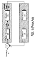
- Cantilever 130 is typically actuated by piezoelectric actuator 110 . Because optical detector 120 only senses the deflection of cantilever 130 , e, and not the absolute position of the probe tip, the control feedback loop is known as an output error only loop.
- output signal u of controller 140 is used as an estimate of the measurement surface as shown in the block diagram of FIG. 1 .
- This typically limits the bandwidth and accuracy of the measurement surface estimate u.
- “C” designates the control portion of the SPM which includes optical detector 120 and controller 140 while “P” designates the plant which includes cantilever 130 and piezoelectric actuator 110 .
- the laser beam reflected from cantilever 130 only falls near the center of optical detector 120 when the probe tip is interacting with measurement surface 105 . When the probe tip is away from measurement surface 105 , cantilever 130 is in an undeflected position. This means that the signal from optical detector 120 is independent of the probe tip height over measurement surface 105 .
- the signal detected by optical detector 120 is not useful for probe tip position information until the probe tip is close enough to measurement surface 105 to interact with surface 105 .
- rapid surface seeks to the measurement surface by a scanning probe microscope are enabled by using an actuator coupled to a position sensor.
- FIG. 1 shows a prior art embodiment
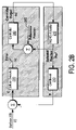
- FIG. 2 a shows an embodiment in accordance with the invention.
- FIG. 2 b shows an embodiment in accordance with the invention.
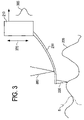
- FIG. 3 shows a measurement surface in contact with a scanning probe tip.
- FIG. 4 a schematically shows various surface height regions in accordance with the invention.
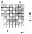
- FIG. 4 b shows surface height estimates as a function of x-y position in accordance with the invention.
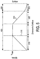
- FIG. 5 shows a seek profile in accordance with the invention.
- FIG. 6 shows an embodiment in accordance with the invention.
- FIGS. 7 a - 7 e show embodiments in accordance with the invention.
- FIG. 8 shows an embodiment in accordance with the invention.
- a more rapid movement of the probe tip to the surface may be accomplished if one has a measurement of the distance of the probe tip from the measurement surface.
- a scanning probe microscope such as an AFM with MEMS actuator 210 having a position sensor can be used to determine the distance of the probe tip from measurement surface 205 .
- the probe tip is mechanically coupled to cantilever 230 .
- MEMS actuator 210 may, for example, be a comb drive based actuator or a MEMS actuator such as described in U.S. Pat. No. 6,657,359 and incorporated herein by reference.
- Optical detector 220 is sensitive to the deflection of cantilever 230 as the attached probe tip moves over measurement surface 205 .
- the input to optical detector 220 is the interaction between the surface elevation r on measurement surface 205 and the position p of cantilever 230 which results in the movement of the reflected laser spot on optical detector 220 .
- Optical detector 220 provides an output error feedback e to controller 240 .
- Controller 240 outputs u, typically a surface estimate, to MEMS actuator 210 .
- MEMS actuator 210 is used for vertical control of cantilever 230 and includes a position detector.
- FIG. 2 b shows the situation when the probe tip is not interacting with measurement surface 205 and cantilever 230 is undeflected.
- optical detector 220 which measures the deflection of cantilever 230 provides no useful information.
- controller 240 outputs an estimate, u, of the position of MEMS actuator 210 .
- the use of the actuator position loop to improve the speed of surface seeks requires an estimate of the position of MEMS actuator 210 when the probe tip first interacts with measurement surface 205 . This then allows rapid surface seeks similar to those typically used for magnetic and optical disk drive actuators. However, those situations are distinguishable from the present problem because potentially small overshoots do not risk catastrophic failure that occurs here were the probe tip to have a “hard” contact with measurement surface 205 during a surface seek.
- FIG. 3 shows measurement surface 205 with statistical estimate 375 of the standard deviation, ⁇ , of the surface height.
- MEMS actuator 210 moves cantilever 230 in the directions of double arrow 379 with the position detector outputting actuator position signal 385 with laser beam 380 reflecting off of cantilever 230 .
- a typical value for the reference position 215 is the position of MEMS actuator 210 at which probe tip 335 interacts with measurement surface 205 as shown in FIG. 3 . In accordance with the invention, this may be obtained by initially bringing probe tip 335 down slowly to measurement surface 205 until the output (e) from optical detector 220 changes significantly.
- Optical detector 220 typically determines position by taking the sum of the intensity in two adjacent quadrants (A+B) and subtracting the sum of the intensity in the two other adjacent quadrants (C+D), e.g. (A+B) ⁇ (C+D).
- cantilever 230 is unflexed, one sum, say (A+B) is typically significantly larger than the other, (C+D).
- By tracking actuator position signal 385 an initial estimate for the surface position is obtained.
- measurement surface 205 were atomically flat and there were no noise from the position detector, the initial estimate for the surface position would typically be sufficient. However, as seen schematically in FIG. 3 , measurement surface 205 is typically not smooth at atomic dimensions.
- the initial estimate for the surface position is to be considered an estimate of the mean surface height. Estimate, s, of the standard deviation, ⁇ , of the surface height may be obtained by determining the position sensor output when surface interaction occurs with scanning probe tip 335 for multiple positions on measurement surface 205 . To avoid damage to scanning probe tip 335 by hard contact with measurement surface 205 , it is necessary to define region 430 about the estimate of mean surface height, z (see FIG. 4 a ).
- Region of safe approach 425 lies outside of region 430 and is where measurement surface 205 may be approached rapidly whereas inside region 430 , measurement surface 205 needs to be approached slowly in “settle” mode to avoid possible damage to scanning probe tip 335 .
- a safe distance for the border between region 430 and region of safe approach 425 is at the 6 ⁇ point which is shown schematically in FIG. 4 a.
- the standard deviation, ⁇ is determined by first calculating the sample estimate of the variance, ⁇ 2 , and taking the square root and N is, in general, the number of scan sample points in a defined region (which here is the scanned image) times the number of scans (which here is one).
- the sample estimate, s 2 , of the variance is given by:
- Another method for determining a value for z settle in accordance with the invention is to determine the minimum and maximum surface heights in a sample set:
- a first surface scan of measurement surface 205 can be obtained using the position detector of MEMS actuator 210 using the procedure described above.
- This first surface scan 400 can be used to provide surface height estimates and approach regions as a function of x-y position as shown in FIG. 4 b .
- darkest regions 410 indicate the greatest surface height while lightest regions 420 indicate the least surface height.
- Regions 410 and 420 may each be a single pixel or a group of pixels.
- the surface height with respect to x-y position can be used to allow faster approaches or seeks to squares on measurement surface 205 .
- the minimum and maximum surface height calculations may be performed by position as:
- z i,j settle max ⁇ z i,j +c i,j 1 ⁇ i,j, max +c i,j 2 z i,j diff ⁇ (12)
- seek or approach profile 500 may be designed as shown in FIG. 5 .
- MEMS actuator 210 initially accelerates cantilever 230 over distance 510 until switching point 515 is reached. After switching point 515 is reached, MEMS actuator 210 may travel at maximum velocity until switching point 516 is reached when MEMS actuator 210 decelerates cantilever 230 over distance 520 . In some embodiments switching point 515 and 516 may be the same point. Over distance 530 , MEMS actuator 210 slowly brings cantilever 230 into its final position.
- Other seek or approach profiles besides seek or approach profile 500 shown in FIG. 5 may be used taking into account the dynamics of the particular MEMS or other actuator used. However, any seek or approach profile generation method that is used is enabled by a position detector that senses the position of the MEMS or other actuator.
- the position of scanning probe tip 335 is typically determined by three distinct components: a high quality, relatively coarse movement stepper motor which is typically capable of moving the entire positioning stage including MEMS actuator 210 vertically on the order of a few millimeters; MEMS actuator 210 which typically is capable of moving cantilever 230 vertically on the order of about 20 ⁇ m; and cantilever 230 which typically deflects vertically on the order of about 20 nm to about 100 nm.
- the stepper motor (not shown) is mechanically coupled to MEMS actuator 210 and operates to move MEMS actuator 210 up and down as indicated by arrows 370 in FIG. 3 .
- a surface seek depends on the starting height.
- a seek region is defined given an estimate of the surface height as described by one of the methods above. If the surface height estimate is within the range of MEMS actuator 210 , then only MEMS actuator 210 is involved in the seek to measurement surface 205 . If the surface height is outside the vertical motion range of MEMS actuator 210 , the stepper motor needs to be used as well. Note, that as an alternative, the stepper motor may be coupled to the sample stage on which measurement surface 205 is located and the stepper motor operates to raise and lower the sample stage. In this example, MEMS motor 210 typically does not move up and down.
- a surface seek is performed as shown in FIG. 6 .
- a surface height estimate is determined, typically using on of the methods described above.
- a height, z settle is established at which to transition to “settle” mode.
- a surface seek is performed to the height, z settle from an initial position above measurement surface 205 that is within the range of MEMS actuator 210 .
- the surface seek to the height, z settle may be performed using any of a number of different embodiments in accordance with the invention.
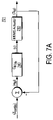
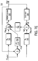
- An exemplary embodiment is shown in FIG. 7 a .
- the height, z settle is input directly as the reference position and controller feedback loop 740 and MEMS actuator 210 will operate to drive MEMS actuator 210 to the reference position, z settle .
- the availability of the output, z M , of position sensor on MEMS actuator 740 allows embodiment 701 to drive MEMS actuator 210 to the reference position, z settle .
- controller feedback loop 740 is represented by the transfer function C M,fb in the frequency domain and MEMS actuator 210 is represented by transfer function P M in the frequency domain
- the output of the position sensor, Z M (f) is related to the input, z settle (f) in the frequency domain by the transfer function where f is a general frequency variable:
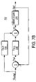
- FIG. 7 b Another exemplary embodiment is shown in FIG. 7 b .
- improved performance is typically obtained by adding feedforward block 744 as shown in FIG. 7 b .
- the addition of feedforward block 744 typically improves the dynamics by moving the reference position, z settle , into MEMS actuator 210 without the delay of passing through controller feedback loop 740 . Representing feedforward block 744 by C M,ff then gives for FIG. 7 b :
- prefilter block 747 is used in place of feedforward block 744 . If
- prefilter block 747 is represented by C M.Pf and F is the filter then
- any of the above embodiments in FIGS. 7 a - 7 c can be implemented using state space methods. This allows the application of methods such as Linear Quadratic Gaussian (LQG) or H ⁇ control with a reference input to remove the system dynamics from the response.
- LQG Linear Quadratic Gaussian
- H ⁇ control with a reference input to remove the system dynamics from the response.
- the gains are defined by the system model and the optimization criteria.
- nonlinear components such as MEMS actuator saturation can be accommodated in the state space model.
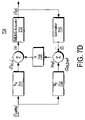
- FIG. 7 d shows an exemplary embodiment implemented using state space methods.
- block 751 implements reference input gain matrix, N u , of the state space controller and is computed from the system model and the state feedback gain, K, of block 758 .
- Reference input gain matrix, N u receives the reference height, z settle , and generates z M,u which drives the steady state error to zero.
- Estimator 755 receives the measured output of the position sensor of MEMS actuator 210 and outputs the state estimate, ⁇ circumflex over (z) ⁇ .
- the error, e M is scaled by the state feedback gain, K.
- FIG. 7 e shows an exemplary embodiment implemented similar to embodiment 704 using state space methods along with integrator 760 .
- Integrator block 760 implements the integrator in a discrete time form, for example, K 1 /(z ⁇ 1), and operates to cause the stable closed-loop system to have zero steady state error in response to a step input.
- Integrator block 760 may include an anti-windup mechanism to accommodate the situation if the control signal saturates.
- the stepper motor is typically needed as part of a surface seek when scanning probe tip 335 has been moved away to replace a sample, MEMS actuator or scanning probe tip 335 .
- the stepper motor is used in accordance with the invention to position the scanning probe tip 335 within the range of MEMS actuator 210 .
- a stepper motor is provided with a maximum speed rating.
- the position commands to the stepper motor are such that the speed ramps up to maximum speed, maintains that speed and then decelerates to zero.
- the precise shape of the trapezoidal speed curve depends on the steeper motor ratings and the distance of travel to the range of MEMS actuator 210 .
- the position commands can be prefiltered to remove any frequencies that would excite the dynamics of MEMS actuator 210 or cantilever 230 .
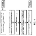
- step 810 it is determined whether the present position of the scanning probe tip 335 is outside of the range of MEMS actuator 210 . If it is not, one proceeds to step 610 in FIG. 6 .
- step 820 if the present position is outside the range of MEMS actuator 210 , determine the stepper motor position, h 1 , when the scanning probe tip 335 is at measurement surface 205 .
- step 830 determine a suitable safety margin ⁇ z safe , for example, c 3 ⁇ +c 4 z diff where c 3 and c 4 are appropriate scaling parameters.
- step 840 MEMS actuator 210 is used to move up scanning probe tip 335 a distance ⁇ z safe relative to the stepper motor.
- step 850 the stepper motor is moved into position h 1 . Note that because MEMS actuator 210 has been moved up a distance ⁇ z safe relative to the stepper motor, scanning probe tip 335 will not be at measurement surface 205 . Finally, MEMS actuator 210 is lowered as described above and shown in FIG. 6 .
- MEMS actuator 210 any appropriate actuator having a position sensor, such as a piezoelectric actuator with a position sensor, may be used in accordance with the invention.
Abstract
Description
- Typical scanning probe microscopes (SPM) such as a typical atomic force microscope (AFM) only sense the probe tip position once the probe tip is in contact with the surface to be scanned. Typical SPMs image a measurement surface by applying a thin probe tip at the end of flexible cantilever to the measurement surface. With respect to
FIG. 1 , as the probe tip moves across the measurement surface, variations in the probe tip height are typically detected by the use of a laser beam reflected off the back ofcantilever 130 that is received byoptical detector 120.Cantilever 130 is typically actuated bypiezoelectric actuator 110. Becauseoptical detector 120 only senses the deflection ofcantilever 130, e, and not the absolute position of the probe tip, the control feedback loop is known as an output error only loop. Typically, output signal u ofcontroller 140 is used as an estimate of the measurement surface as shown in the block diagram ofFIG. 1 . This typically limits the bandwidth and accuracy of the measurement surface estimate u. Note that inFIG. 1 “C” designates the control portion of the SPM which includesoptical detector 120 andcontroller 140 while “P” designates the plant which includescantilever 130 andpiezoelectric actuator 110. Furthermore, the laser beam reflected fromcantilever 130 only falls near the center ofoptical detector 120 when the probe tip is interacting withmeasurement surface 105. When the probe tip is away frommeasurement surface 105,cantilever 130 is in an undeflected position. This means that the signal fromoptical detector 120 is independent of the probe tip height overmeasurement surface 105. Hence, the signal detected byoptical detector 120 is not useful for probe tip position information until the probe tip is close enough tomeasurement surface 105 to interact withsurface 105. This typically creates difficulties for fast seeks ofmeasurement surface 105 because the speed of the approach tomeasurement surface 105 typically needs to be slow enough so that the approach can be stopped as soon asmeasurement surface 105 is detected byoptical detector 120. - In accordance with the invention, rapid surface seeks to the measurement surface by a scanning probe microscope are enabled by using an actuator coupled to a position sensor.
-
FIG. 1 shows a prior art embodiment. -
FIG. 2 a shows an embodiment in accordance with the invention. -
FIG. 2 b shows an embodiment in accordance with the invention. -
FIG. 3 shows a measurement surface in contact with a scanning probe tip. -
FIG. 4 a schematically shows various surface height regions in accordance with the invention. -
FIG. 4 b shows surface height estimates as a function of x-y position in accordance with the invention. -
FIG. 5 shows a seek profile in accordance with the invention. -
FIG. 6 shows an embodiment in accordance with the invention. -
FIGS. 7 a-7 e show embodiments in accordance with the invention. -
FIG. 8 shows an embodiment in accordance with the invention. - In accordance with the invention, a more rapid movement of the probe tip to the surface may be accomplished if one has a measurement of the distance of the probe tip from the measurement surface. As shown in the closed loop block diagram of
FIG. 2 a, a scanning probe microscope such as an AFM withMEMS actuator 210 having a position sensor can be used to determine the distance of the probe tip frommeasurement surface 205. The probe tip is mechanically coupled tocantilever 230.MEMS actuator 210 may, for example, be a comb drive based actuator or a MEMS actuator such as described in U.S. Pat. No. 6,657,359 and incorporated herein by reference.Optical detector 220 is sensitive to the deflection ofcantilever 230 as the attached probe tip moves overmeasurement surface 205. The input tooptical detector 220 is the interaction between the surface elevation r onmeasurement surface 205 and the position p ofcantilever 230 which results in the movement of the reflected laser spot onoptical detector 220.Optical detector 220 provides an output error feedback e to controller 240.Controller 240 outputs u, typically a surface estimate, toMEMS actuator 210. MEMSactuator 210 is used for vertical control ofcantilever 230 and includes a position detector.FIG. 2 b shows the situation when the probe tip is not interacting withmeasurement surface 205 andcantilever 230 is undeflected. The output fromoptical detector 220 which measures the deflection ofcantilever 230 provides no useful information. However, it is still possible to close the actuator position loop tocontroller 240 asFIG. 2 b shows by providingreference position 215 for the actuator position loop to follow. Here controller 240 outputs an estimate, u, of the position ofMEMS actuator 210. The use of the actuator position loop to improve the speed of surface seeks requires an estimate of the position ofMEMS actuator 210 when the probe tip first interacts withmeasurement surface 205. This then allows rapid surface seeks similar to those typically used for magnetic and optical disk drive actuators. However, those situations are distinguishable from the present problem because potentially small overshoots do not risk catastrophic failure that occurs here were the probe tip to have a “hard” contact withmeasurement surface 205 during a surface seek. -
FIG. 3 showsmeasurement surface 205 withstatistical estimate 375 of the standard deviation, σ, of the surface height.MEMS actuator 210 movescantilever 230 in the directions of double arrow 379 with the position detector outputtingactuator position signal 385 withlaser beam 380 reflecting off ofcantilever 230. A typical value for thereference position 215 is the position ofMEMS actuator 210 at whichprobe tip 335 interacts withmeasurement surface 205 as shown inFIG. 3 . In accordance with the invention, this may be obtained by initially bringingprobe tip 335 down slowly tomeasurement surface 205 until the output (e) fromoptical detector 220 changes significantly.Optical detector 220 typically determines position by taking the sum of the intensity in two adjacent quadrants (A+B) and subtracting the sum of the intensity in the two other adjacent quadrants (C+D), e.g. (A+B)−(C+D). Whencantilever 230 is unflexed, one sum, say (A+B) is typically significantly larger than the other, (C+D). Whenprobe tip 335 makes contact withmeasurement surface 205, the output (e) changes and the output (e) goes towards or through a zero crossing. Note that the sum of A, B, C, D is a maximum when (A+B)−(C+D)=0. When this occurs it is apparent thatprobe tip 335 is interacting withmeasurement surface 205. By trackingactuator position signal 385 an initial estimate for the surface position is obtained. - If
measurement surface 205 were atomically flat and there were no noise from the position detector, the initial estimate for the surface position would typically be sufficient. However, as seen schematically inFIG. 3 ,measurement surface 205 is typically not smooth at atomic dimensions. The initial estimate for the surface position is to be considered an estimate of the mean surface height. Estimate, s, of the standard deviation, σ, of the surface height may be obtained by determining the position sensor output when surface interaction occurs withscanning probe tip 335 for multiple positions onmeasurement surface 205. To avoid damage to scanningprobe tip 335 by hard contact withmeasurement surface 205, it is necessary to defineregion 430 about the estimate of mean surface height,z (seeFIG. 4 a). Region ofsafe approach 425 lies outside ofregion 430 and is wheremeasurement surface 205 may be approached rapidly whereas insideregion 430,measurement surface 205 needs to be approached slowly in “settle” mode to avoid possible damage to scanningprobe tip 335. For example, formeasurement surface 205 it might be established that a safe distance for the border betweenregion 430 and region ofsafe approach 425 is at the 6 σ point which is shown schematically inFIG. 4 a. - To use the above method requires an estimate of the mean surface height,
z , as well as the standard deviation, σ, about the mean surface height,z ofmeasurement surface 205. The typical estimate for mean surface height,z is given by: -
- where the standard deviation, σ, is determined by first calculating the sample estimate of the variance, σ2, and taking the square root and N is, in general, the number of scan sample points in a defined region (which here is the scanned image) times the number of scans (which here is one). The sample estimate, s2, of the variance is given by:
-
- so that the estimate of the standard deviation, σ, is given by s. Typically, the distinction between s and σ is dropped so that σ is the sample standard deviation, s. This provides a measure for the height, zsettle, where the seek operation is changed to “settle” mode and is given by:
-
z settle =z +c 1σ (3) - where c1 is an appropriate scaling constant.
- Another method for determining a value for zsettle in accordance with the invention, is to determine the minimum and maximum surface heights in a sample set:
-
- and calculate the difference, zdiff, between the minimum and maximum surface heights, zmin and zmax, respectively. This allows the determination of a value for zsettle given by:
-
z settle =z max +c 2 z diff (5) - where c2 is an appropriate scaling constant. The two methods given by Eq. (3) and Eq. (5) for zsettle may be used in combination to give, for example:
-
z settle=max{z +c 1 σ, z max +c 2 z diff} (6) - Another method of estimating the surface height becomes useful when surface scans are to be repeated. A first surface scan of
measurement surface 205 can be obtained using the position detector ofMEMS actuator 210 using the procedure described above. Thisfirst surface scan 400 can be used to provide surface height estimates and approach regions as a function of x-y position as shown inFIG. 4 b. For example,darkest regions 410 indicate the greatest surface height whilelightest regions 420 indicate the least surface height.Regions measurement surface 205. - Surface height estimates with respect to x-y position can be implemented by a variation of Eq. (1), so that the average height for an x-y position is given by:
-
- where i represents the ith x-position and j represents the jth y-position. The standard deviation at the ith x-position and the jth y-position, σi,j is given by:
-
- and this can be used to provide a measure for the height, zi,j settle, where the seek operation is changed to “settle” mode for each approach region and is given by:
-
z i,j settle =z i,j +c i,j 1σi,j (9) - where ci,j 1 is an appropriate position dependent scaling constant.
- Similarly to the above single scan method discussed above, the minimum and maximum surface height calculations may be performed by position as:
-
- and calculate the difference, Zi,j diff, between the minimum and maximum surface heights at each position, zi,j min and zi,j max, respectively. This allows the determination of a value for zi,j settle given by:
-
z i,j settle =z i,j max +c i,j 2 z i,j diff (11) - Again the two methods given by Eq. (9) and Eq. (11) for zi,j settle may be combined to give, for example:
-
z i,j settle=max{z i,j +c i,j 1σi,j, max +c i,j 2 z i,j diff} (12) - Given estimates of surface heights and regions of
safe approach 425, seek orapproach profile 500 may be designed as shown inFIG. 5 . MEMS actuator 210 initially acceleratescantilever 230 overdistance 510 until switchingpoint 515 is reached. After switchingpoint 515 is reached, MEMS actuator 210 may travel at maximum velocity until switching point 516 is reached when MEMS actuator 210 deceleratescantilever 230 overdistance 520. In someembodiments switching point 515 and 516 may be the same point. Overdistance 530, MEMS actuator 210 slowly bringscantilever 230 into its final position. Other seek or approach profiles besides seek orapproach profile 500 shown inFIG. 5 may be used taking into account the dynamics of the particular MEMS or other actuator used. However, any seek or approach profile generation method that is used is enabled by a position detector that senses the position of the MEMS or other actuator. - In accordance with the invention, the position of
scanning probe tip 335 is typically determined by three distinct components: a high quality, relatively coarse movement stepper motor which is typically capable of moving the entire positioning stage including MEMS actuator 210 vertically on the order of a few millimeters;MEMS actuator 210 which typically is capable of movingcantilever 230 vertically on the order of about 20 μm; andcantilever 230 which typically deflects vertically on the order of about 20 nm to about 100 nm. The stepper motor (not shown) is mechanically coupled toMEMS actuator 210 and operates to move MEMS actuator 210 up and down as indicated byarrows 370 inFIG. 3 . Hence, a surface seek depends on the starting height. A seek region is defined given an estimate of the surface height as described by one of the methods above. If the surface height estimate is within the range ofMEMS actuator 210, then onlyMEMS actuator 210 is involved in the seek tomeasurement surface 205. If the surface height is outside the vertical motion range ofMEMS actuator 210, the stepper motor needs to be used as well. Note, that as an alternative, the stepper motor may be coupled to the sample stage on whichmeasurement surface 205 is located and the stepper motor operates to raise and lower the sample stage. In this example,MEMS motor 210 typically does not move up and down. - When the initial position above
measurement surface 205 is within the range ofMEMS actuator 210, the stepper motor is typically not used to drive the positioning stage. This situation typically occurs if a non-raster scan is performed or the tip is moved offsurface 205 at the conclusion of a measurement. In accordance with the invention, a surface seek is performed as shown inFIG. 6 . Instep 610, a surface height estimate is determined, typically using on of the methods described above. In step 620, a height, zsettle is established at which to transition to “settle” mode. Instep 630, a surface seek is performed to the height, zsettle from an initial position abovemeasurement surface 205 that is within the range ofMEMS actuator 210. - The surface seek to the height, zsettle, may be performed using any of a number of different embodiments in accordance with the invention. An exemplary embodiment is shown in
FIG. 7 a. Inembodiment 701 shown inFIG. 7 a, the height, zsettle, is input directly as the reference position andcontroller feedback loop 740 andMEMS actuator 210 will operate to drive MEMS actuator 210 to the reference position, zsettle. The availability of the output, zM, of position sensor onMEMS actuator 740 allowsembodiment 701 to drive MEMS actuator 210 to the reference position, zsettle. Ifcontroller feedback loop 740 is represented by the transfer function CM,fb in the frequency domain andMEMS actuator 210 is represented by transfer function PM in the frequency domain, the output of the position sensor, ZM (f), is related to the input, zsettle (f) in the frequency domain by the transfer function where f is a general frequency variable: -
- Another exemplary embodiment is shown in
FIG. 7 b. Inembodiment 702 improved performance is typically obtained by adding feedforward block 744 as shown inFIG. 7 b. The addition of feedforward block 744 typically improves the dynamics by moving the reference position, zsettle, intoMEMS actuator 210 without the delay of passing throughcontroller feedback loop 740. Representing feedforward block 744 by CM,ff then gives forFIG. 7 b: -
- which if CM,ff≈PM −1 gives:
-
- Another exemplary embodiment is shown in
FIG. 7 c. Inembodiment 703,prefilter block 747 is used in place of feedforward block 744. If -
- where
prefilter block 747 is represented by CM.Pf and F is the filter then -
- Choosing the filter, F to be F=PMCM,fbFLP with FLP a low pass filter selected to remove high frequency noise gives:
-
- Any of the above embodiments in
FIGS. 7 a-7 c can be implemented using state space methods. This allows the application of methods such as Linear Quadratic Gaussian (LQG) or H∞ control with a reference input to remove the system dynamics from the response. With a state space control system, the gains are defined by the system model and the optimization criteria. Furthermore, nonlinear components such as MEMS actuator saturation can be accommodated in the state space model. -
FIG. 7 d shows an exemplary embodiment implemented using state space methods. Inembodiment 704, block 751 implements reference input gain matrix, Nu, of the state space controller and is computed from the system model and the state feedback gain, K, ofblock 758. Reference input gain matrix, Nu, receives the reference height, zsettle, and generates zM,u which drives the steady state error to zero.Estimator 755 receives the measured output of the position sensor ofMEMS actuator 210 and outputs the state estimate, {circumflex over (z)}.Block 751 implements gain matrix, Nz, which receives the reference height, zsettle, and generates the reference state, ZM,Zref which is used together with state estimate, {circumflex over (z)} to generate the error, eM=(zM,Zref−{circumflex over (z)}). The error, eM, is scaled by the state feedback gain, K. -
FIG. 7 e shows an exemplary embodiment implemented similar toembodiment 704 using state space methods along withintegrator 760.Integrator block 760 implements the integrator in a discrete time form, for example, K1/(z−1), and operates to cause the stable closed-loop system to have zero steady state error in response to a step input.Integrator block 760 receives the error, e′M=(zsettle−zM) which is output to summingblock 762.Integrator block 760 may include an anti-windup mechanism to accommodate the situation if the control signal saturates. - If the speed of the seek is pushed to the point that limits of
MEMS actuator 210 are reached, then a time optimal or Proximate Time optimal control method may be used. However, these systems are less well studied of multi-resonant systems. - The stepper motor is typically needed as part of a surface seek when scanning
probe tip 335 has been moved away to replace a sample, MEMS actuator orscanning probe tip 335. The stepper motor is used in accordance with the invention to position thescanning probe tip 335 within the range ofMEMS actuator 210. Typically, a stepper motor is provided with a maximum speed rating. Hence, the position commands to the stepper motor are such that the speed ramps up to maximum speed, maintains that speed and then decelerates to zero. The precise shape of the trapezoidal speed curve depends on the steeper motor ratings and the distance of travel to the range ofMEMS actuator 210. The position commands can be prefiltered to remove any frequencies that would excite the dynamics ofMEMS actuator 210 orcantilever 230. - In accordance with the invention, a method for a seek using the stepper motor is shown in
FIG. 8 . Instep 810, it is determined whether the present position of thescanning probe tip 335 is outside of the range ofMEMS actuator 210. If it is not, one proceeds to step 610 inFIG. 6 . In step 820, if the present position is outside the range ofMEMS actuator 210, determine the stepper motor position, h1, when thescanning probe tip 335 is atmeasurement surface 205. Instep 830, determine a suitable safety margin Δzsafe, for example, c3σ+c4zdiff where c3 and c4 are appropriate scaling parameters. Instep 840, MEMS actuator 210 is used to move up scanning probe tip 335 a distance Δzsafe relative to the stepper motor. Instep 850, the stepper motor is moved into position h1. Note that because MEMS actuator 210 has been moved up a distance Δzsafe relative to the stepper motor, scanningprobe tip 335 will not be atmeasurement surface 205. Finally, MEMS actuator 210 is lowered as described above and shown inFIG. 6 . - It should be noted that while the embodiments in accordance with the invention are described with respect to
MEMS actuator 210, it is to be understood that any appropriate actuator having a position sensor, such as a piezoelectric actuator with a position sensor, may be used in accordance with the invention.
Claims (20)
Priority Applications (1)
| Application Number | Priority Date | Filing Date | Title |
|---|---|---|---|
| US11/553,702 US7472585B2 (en) | 2006-10-27 | 2006-10-27 | Method for rapid seeks to the measurement surface for a scanning probe microscope |
Applications Claiming Priority (1)
| Application Number | Priority Date | Filing Date | Title |
|---|---|---|---|
| US11/553,702 US7472585B2 (en) | 2006-10-27 | 2006-10-27 | Method for rapid seeks to the measurement surface for a scanning probe microscope |
Publications (2)
| Publication Number | Publication Date |
|---|---|
| US20080098804A1 true US20080098804A1 (en) | 2008-05-01 |
| US7472585B2 US7472585B2 (en) | 2009-01-06 |
Family
ID=39363297
Family Applications (1)
| Application Number | Title | Priority Date | Filing Date |
|---|---|---|---|
| US11/553,702 Expired - Fee Related US7472585B2 (en) | 2006-10-27 | 2006-10-27 | Method for rapid seeks to the measurement surface for a scanning probe microscope |
Country Status (1)
| Country | Link |
|---|---|
| US (1) | US7472585B2 (en) |
Cited By (1)
| Publication number | Priority date | Publication date | Assignee | Title |
|---|---|---|---|---|
| US7511524B1 (en) * | 2007-12-28 | 2009-03-31 | Phicom Corporation | Contact tip structure of a connecting element |
Families Citing this family (6)
| Publication number | Priority date | Publication date | Assignee | Title |
|---|---|---|---|---|
| KR100869046B1 (en) * | 2007-02-09 | 2008-11-18 | 한국기계연구원 | Afm probe |
| US8904560B2 (en) * | 2007-05-07 | 2014-12-02 | Bruker Nano, Inc. | Closed loop controller and method for fast scanning probe microscopy |
| US8838257B1 (en) * | 2007-10-04 | 2014-09-16 | Marvell International Ltd. | Controller and design support apparatus |
| US9527732B2 (en) * | 2010-09-23 | 2016-12-27 | Seagate Technology Llc | Methods and devices for correcting errors in atomic force microscopy |
| US8695746B2 (en) | 2011-03-21 | 2014-04-15 | Polaris Industries Inc. | Three wheeled vehicle |
| KR101710337B1 (en) * | 2015-06-02 | 2017-02-28 | 파크시스템스 주식회사 | Measurement apparatus and method with adaptive scan rate |
Citations (6)
| Publication number | Priority date | Publication date | Assignee | Title |
|---|---|---|---|---|
| US5847383A (en) * | 1995-10-05 | 1998-12-08 | Olympus Optical Co., Ltd. | Approaching device of scanning probe microscope |
| US5852232A (en) * | 1997-01-02 | 1998-12-22 | Kla-Tencor Corporation | Acoustic sensor as proximity detector |
| US6265718B1 (en) * | 1992-03-13 | 2001-07-24 | Thermomicroscopes, Corp. | Scanning probe microscope with scan correction |
| US6960765B2 (en) * | 2000-07-24 | 2005-11-01 | Hitachi, Ltd. | Probe driving method, and probe apparatus |
| US7066014B2 (en) * | 2003-09-30 | 2006-06-27 | Iowa State University Research Foundation, Inc. | Method to transiently detect samples in atomic force microscopes |
| US20060230474A1 (en) * | 2005-04-12 | 2006-10-12 | Mininni Paul I | Method and apparatus for rapid automatic engagement of a prove |
-
2006
- 2006-10-27 US US11/553,702 patent/US7472585B2/en not_active Expired - Fee Related
Patent Citations (6)
| Publication number | Priority date | Publication date | Assignee | Title |
|---|---|---|---|---|
| US6265718B1 (en) * | 1992-03-13 | 2001-07-24 | Thermomicroscopes, Corp. | Scanning probe microscope with scan correction |
| US5847383A (en) * | 1995-10-05 | 1998-12-08 | Olympus Optical Co., Ltd. | Approaching device of scanning probe microscope |
| US5852232A (en) * | 1997-01-02 | 1998-12-22 | Kla-Tencor Corporation | Acoustic sensor as proximity detector |
| US6960765B2 (en) * | 2000-07-24 | 2005-11-01 | Hitachi, Ltd. | Probe driving method, and probe apparatus |
| US7066014B2 (en) * | 2003-09-30 | 2006-06-27 | Iowa State University Research Foundation, Inc. | Method to transiently detect samples in atomic force microscopes |
| US20060230474A1 (en) * | 2005-04-12 | 2006-10-12 | Mininni Paul I | Method and apparatus for rapid automatic engagement of a prove |
Cited By (1)
| Publication number | Priority date | Publication date | Assignee | Title |
|---|---|---|---|---|
| US7511524B1 (en) * | 2007-12-28 | 2009-03-31 | Phicom Corporation | Contact tip structure of a connecting element |
Also Published As
| Publication number | Publication date |
|---|---|
| US7472585B2 (en) | 2009-01-06 |
Similar Documents
| Publication | Publication Date | Title |
|---|---|---|
| US7472585B2 (en) | Method for rapid seeks to the measurement surface for a scanning probe microscope | |
| US9523707B2 (en) | Closed loop controller and method for fast scanning probe microscopy | |
| US6234009B1 (en) | Controlling motion of a scanning force microscope probe tip moving into engagement with a sample surface | |
| Rana et al. | A survey of methods used to control piezoelectric tube scanners in high‐speed AFM imaging | |
| US7665349B2 (en) | Method and apparatus for rapid automatic engagement of a probe | |
| EP0584440B1 (en) | Method of measuring a surface profile using an atomic force microscope | |
| US5773824A (en) | Method for improving measurement accuracy using active lateral scanning control of a probe | |
| CN109863408B (en) | Method, device and system for designing scanning tunnel microscope control system | |
| DE102016214658A1 (en) | Scanning probe microscope and method for inspecting a sample surface | |
| US20080087820A1 (en) | Probe control method for scanning probe microscope | |
| Tajaddodianfar et al. | Stability analysis of a scanning tunneling microscope control system | |
| US10041970B2 (en) | High speed adaptive-multi-loop mode imaging atomic force microscopy | |
| Habibullah et al. | A robust control approach for high-speed nanopositioning applications | |
| JP6584113B2 (en) | Spread resistance measuring method and spread resistance microscope | |
| US9766266B2 (en) | Method of advancing a probe tip of a scanning microscopy device towards a sample surface, and device therefore | |
| US9891246B2 (en) | Harmonic feedback atomic force microscopy | |
| JP4904495B2 (en) | High-band atomic force microscope | |
| US7944799B2 (en) | Optical information apparatus with gap control system | |
| US11099210B2 (en) | Feedback correction in sub-resonant tapping mode of an atomic force microscope | |
| Huang et al. | Iterative Learning Controller with Learning Gain Optimization and Online Data Adjustment for Atomic Force Microscope | |
| JP2008215930A (en) | Measuring method and measuring device of sample surface | |
| JP2004069445A (en) | Scanning type probe microscope | |
| Tuma et al. | A hybrid control approach to nanopositioning | |
| JPH11326347A (en) | Scan type probe microscope | |
| Chang | High-speed atomic force microscopy through local raster scanning |
Legal Events
| Date | Code | Title | Description |
|---|---|---|---|
| AS | Assignment |
Owner name: AGILENT TECHNOLOGIES INC, COLORADO Free format text: CORRECTIVE ASSIGNMENT TO CORRECT THE SERIAL NUMBER ON A DOCUMENT PREVIOUSLY RECORDED ON REEL 018447 FRAME 0661;ASSIGNOR:ABRAMOVITCH, DANIEL Y.;REEL/FRAME:018901/0985 Effective date: 20061027 |
|
| CC | Certificate of correction | ||
| FPAY | Fee payment |
Year of fee payment: 4 |
|
| AS | Assignment |
Owner name: KEYSIGHT TECHNOLOGIES, INC., CALIFORNIA Free format text: ASSIGNMENT OF ASSIGNORS INTEREST;ASSIGNOR:AGILENT TECHNOLOGIES, INC.;REEL/FRAME:033746/0714 Effective date: 20140801 |
|
| REMI | Maintenance fee reminder mailed | ||
| LAPS | Lapse for failure to pay maintenance fees | ||
| STCH | Information on status: patent discontinuation |
Free format text: PATENT EXPIRED DUE TO NONPAYMENT OF MAINTENANCE FEES UNDER 37 CFR 1.362 |
|
| FP | Lapsed due to failure to pay maintenance fee |
Effective date: 20170106 |