US20080128362A1 - Method of ultrasonically treating a continuous flow of fluid - Google Patents
Method of ultrasonically treating a continuous flow of fluid Download PDFInfo
- Publication number
- US20080128362A1 US20080128362A1 US11/566,681 US56668106A US2008128362A1 US 20080128362 A1 US20080128362 A1 US 20080128362A1 US 56668106 A US56668106 A US 56668106A US 2008128362 A1 US2008128362 A1 US 2008128362A1
- Authority
- US
- United States
- Prior art keywords
- fluid
- matter
- ultrasonic waves
- objects
- laminas
- Prior art date
- Legal status (The legal status is an assumption and is not a legal conclusion. Google has not performed a legal analysis and makes no representation as to the accuracy of the status listed.)
- Granted
Links
- 239000012530 fluid Substances 0.000 title claims abstract description 296
- 238000000034 method Methods 0.000 title claims abstract description 61
- 241000761557 Lamina Species 0.000 claims abstract description 54
- 238000002604 ultrasonography Methods 0.000 claims description 19
- 239000000126 substance Substances 0.000 claims description 9
- 239000003054 catalyst Substances 0.000 claims 1
- 230000003134 recirculating effect Effects 0.000 claims 1
- 238000006243 chemical reaction Methods 0.000 abstract description 9
- 230000001939 inductive effect Effects 0.000 abstract description 5
- 238000004140 cleaning Methods 0.000 abstract description 4
- 231100001231 less toxic Toxicity 0.000 abstract description 4
- 230000001954 sterilising effect Effects 0.000 abstract description 4
- 230000000415 inactivating effect Effects 0.000 abstract description 3
- 230000002147 killing effect Effects 0.000 abstract description 3
- 231100000331 toxic Toxicity 0.000 abstract description 3
- 230000002588 toxic effect Effects 0.000 abstract description 3
- 238000011282 treatment Methods 0.000 description 10
- 102000004169 proteins and genes Human genes 0.000 description 8
- 108090000623 proteins and genes Proteins 0.000 description 8
- 239000012528 membrane Substances 0.000 description 6
- 239000003153 chemical reaction reagent Substances 0.000 description 5
- 230000005484 gravity Effects 0.000 description 5
- 241000700605 Viruses Species 0.000 description 4
- 210000004027 cell Anatomy 0.000 description 4
- 230000001413 cellular effect Effects 0.000 description 4
- 239000007789 gas Substances 0.000 description 4
- 239000000463 material Substances 0.000 description 4
- 238000003491 array Methods 0.000 description 3
- -1 but not limited Substances 0.000 description 3
- 239000003795 chemical substances by application Substances 0.000 description 3
- 238000004880 explosion Methods 0.000 description 3
- 230000001965 increasing effect Effects 0.000 description 3
- 239000007787 solid Substances 0.000 description 3
- ZAMOUSCENKQFHK-UHFFFAOYSA-N Chlorine atom Chemical compound [Cl] ZAMOUSCENKQFHK-UHFFFAOYSA-N 0.000 description 2
- 102000004190 Enzymes Human genes 0.000 description 2
- 108090000790 Enzymes Proteins 0.000 description 2
- CBENFWSGALASAD-UHFFFAOYSA-N Ozone Chemical compound [O-][O+]=O CBENFWSGALASAD-UHFFFAOYSA-N 0.000 description 2
- 230000015572 biosynthetic process Effects 0.000 description 2
- 229910052801 chlorine Inorganic materials 0.000 description 2
- 239000000460 chlorine Substances 0.000 description 2
- 230000001877 deodorizing effect Effects 0.000 description 2
- 230000001419 dependent effect Effects 0.000 description 2
- 230000003628 erosive effect Effects 0.000 description 2
- 238000005204 segregation Methods 0.000 description 2
- 230000004083 survival effect Effects 0.000 description 2
- 241000894006 Bacteria Species 0.000 description 1
- WKBOTKDWSSQWDR-UHFFFAOYSA-N Bromine atom Chemical compound [Br] WKBOTKDWSSQWDR-UHFFFAOYSA-N 0.000 description 1
- 241000195493 Cryptophyta Species 0.000 description 1
- 241000233866 Fungi Species 0.000 description 1
- 240000004808 Saccharomyces cerevisiae Species 0.000 description 1
- 239000000853 adhesive Substances 0.000 description 1
- 230000001070 adhesive effect Effects 0.000 description 1
- 230000000843 anti-fungal effect Effects 0.000 description 1
- 230000000840 anti-viral effect Effects 0.000 description 1
- 229940121375 antifungal agent Drugs 0.000 description 1
- 230000003115 biocidal effect Effects 0.000 description 1
- GDTBXPJZTBHREO-UHFFFAOYSA-N bromine Substances BrBr GDTBXPJZTBHREO-UHFFFAOYSA-N 0.000 description 1
- 229910052794 bromium Inorganic materials 0.000 description 1
- 231100000481 chemical toxicant Toxicity 0.000 description 1
- 210000000805 cytoplasm Anatomy 0.000 description 1
- 230000007423 decrease Effects 0.000 description 1
- 239000010419 fine particle Substances 0.000 description 1
- 238000004519 manufacturing process Methods 0.000 description 1
- 244000005700 microbiome Species 0.000 description 1
- 102000039446 nucleic acids Human genes 0.000 description 1
- 108020004707 nucleic acids Proteins 0.000 description 1
- 150000007523 nucleic acids Chemical class 0.000 description 1
- 238000005457 optimization Methods 0.000 description 1
- 239000008188 pellet Substances 0.000 description 1
- 150000002978 peroxides Chemical class 0.000 description 1
- 239000011148 porous material Substances 0.000 description 1
- 230000002829 reductive effect Effects 0.000 description 1
- 230000000717 retained effect Effects 0.000 description 1
- 150000003839 salts Chemical class 0.000 description 1
- 235000000346 sugar Nutrition 0.000 description 1
- 150000008163 sugars Chemical class 0.000 description 1
- 238000009210 therapy by ultrasound Methods 0.000 description 1
- 239000003440 toxic substance Substances 0.000 description 1
- 230000003313 weakening effect Effects 0.000 description 1
Images

Classifications
-
- A—HUMAN NECESSITIES
- A61—MEDICAL OR VETERINARY SCIENCE; HYGIENE
- A61L—METHODS OR APPARATUS FOR STERILISING MATERIALS OR OBJECTS IN GENERAL; DISINFECTION, STERILISATION OR DEODORISATION OF AIR; CHEMICAL ASPECTS OF BANDAGES, DRESSINGS, ABSORBENT PADS OR SURGICAL ARTICLES; MATERIALS FOR BANDAGES, DRESSINGS, ABSORBENT PADS OR SURGICAL ARTICLES
- A61L2/00—Methods or apparatus for disinfecting or sterilising materials or objects other than foodstuffs or contact lenses; Accessories therefor
- A61L2/02—Methods or apparatus for disinfecting or sterilising materials or objects other than foodstuffs or contact lenses; Accessories therefor using physical phenomena
- A61L2/025—Ultrasonics
-
- A—HUMAN NECESSITIES
- A61—MEDICAL OR VETERINARY SCIENCE; HYGIENE
- A61L—METHODS OR APPARATUS FOR STERILISING MATERIALS OR OBJECTS IN GENERAL; DISINFECTION, STERILISATION OR DEODORISATION OF AIR; CHEMICAL ASPECTS OF BANDAGES, DRESSINGS, ABSORBENT PADS OR SURGICAL ARTICLES; MATERIALS FOR BANDAGES, DRESSINGS, ABSORBENT PADS OR SURGICAL ARTICLES
- A61L2/00—Methods or apparatus for disinfecting or sterilising materials or objects other than foodstuffs or contact lenses; Accessories therefor
- A61L2/02—Methods or apparatus for disinfecting or sterilising materials or objects other than foodstuffs or contact lenses; Accessories therefor using physical phenomena
-
- A—HUMAN NECESSITIES
- A61—MEDICAL OR VETERINARY SCIENCE; HYGIENE
- A61L—METHODS OR APPARATUS FOR STERILISING MATERIALS OR OBJECTS IN GENERAL; DISINFECTION, STERILISATION OR DEODORISATION OF AIR; CHEMICAL ASPECTS OF BANDAGES, DRESSINGS, ABSORBENT PADS OR SURGICAL ARTICLES; MATERIALS FOR BANDAGES, DRESSINGS, ABSORBENT PADS OR SURGICAL ARTICLES
- A61L2/00—Methods or apparatus for disinfecting or sterilising materials or objects other than foodstuffs or contact lenses; Accessories therefor
- A61L2/16—Methods or apparatus for disinfecting or sterilising materials or objects other than foodstuffs or contact lenses; Accessories therefor using chemical substances
- A61L2/18—Liquid substances or solutions comprising solids or dissolved gases
- A61L2/183—Ozone dissolved in a liquid
-
- B—PERFORMING OPERATIONS; TRANSPORTING
- B01—PHYSICAL OR CHEMICAL PROCESSES OR APPARATUS IN GENERAL
- B01J—CHEMICAL OR PHYSICAL PROCESSES, e.g. CATALYSIS OR COLLOID CHEMISTRY; THEIR RELEVANT APPARATUS
- B01J19/00—Chemical, physical or physico-chemical processes in general; Their relevant apparatus
- B01J19/08—Processes employing the direct application of electric or wave energy, or particle radiation; Apparatus therefor
- B01J19/10—Processes employing the direct application of electric or wave energy, or particle radiation; Apparatus therefor employing sonic or ultrasonic vibrations
-
- B—PERFORMING OPERATIONS; TRANSPORTING
- B08—CLEANING
- B08B—CLEANING IN GENERAL; PREVENTION OF FOULING IN GENERAL
- B08B3/00—Cleaning by methods involving the use or presence of liquid or steam
- B08B3/04—Cleaning involving contact with liquid
- B08B3/10—Cleaning involving contact with liquid with additional treatment of the liquid or of the object being cleaned, e.g. by heat, by electricity or by vibration
- B08B3/12—Cleaning involving contact with liquid with additional treatment of the liquid or of the object being cleaned, e.g. by heat, by electricity or by vibration by sonic or ultrasonic vibrations
-
- B—PERFORMING OPERATIONS; TRANSPORTING
- B01—PHYSICAL OR CHEMICAL PROCESSES OR APPARATUS IN GENERAL
- B01J—CHEMICAL OR PHYSICAL PROCESSES, e.g. CATALYSIS OR COLLOID CHEMISTRY; THEIR RELEVANT APPARATUS
- B01J2219/00—Chemical, physical or physico-chemical processes in general; Their relevant apparatus
- B01J2219/00049—Controlling or regulating processes
- B01J2219/00191—Control algorithm
-
- B—PERFORMING OPERATIONS; TRANSPORTING
- B01—PHYSICAL OR CHEMICAL PROCESSES OR APPARATUS IN GENERAL
- B01J—CHEMICAL OR PHYSICAL PROCESSES, e.g. CATALYSIS OR COLLOID CHEMISTRY; THEIR RELEVANT APPARATUS
- B01J2219/00—Chemical, physical or physico-chemical processes in general; Their relevant apparatus
- B01J2219/08—Processes employing the direct application of electric or wave energy, or particle radiation; Apparatus therefor
- B01J2219/0873—Materials to be treated
- B01J2219/0892—Materials to be treated involving catalytically active material
-
- C—CHEMISTRY; METALLURGY
- C02—TREATMENT OF WATER, WASTE WATER, SEWAGE, OR SLUDGE
- C02F—TREATMENT OF WATER, WASTE WATER, SEWAGE, OR SLUDGE
- C02F1/00—Treatment of water, waste water, or sewage
- C02F1/34—Treatment of water, waste water, or sewage with mechanical oscillations
- C02F1/36—Treatment of water, waste water, or sewage with mechanical oscillations ultrasonic vibrations
Definitions
- the present invention relates to a method of treating a continuous flow fluid that may be used to degrade matter within fluids, remove matter from fluids, separate matter within a fluid by density, sterilize fluids, and/or degrade toxic chemicals within a fluid.
- the method of the present invention may also be utilized to clean, sterilize, and/or deodorize objects submerged within a continuous flow of fluid.
- Subjecting a fluid to ultrasonic waves enables various treatments of the fluid and objects or matter within the fluid. For instance, submerging objects within a fluid subjected to ultrasonic waves can clean the objects. Placing a piece of solid matter such as, but not limited to, a salt pellet within a fluid subjected to ultrasonic waves causes erosion of the solid matter. Furthermore, matter bonded together may be separated when placed within a fluid subjected to ultrasonic waves. Ultrasonic waves traveling within a fluid may also be utilized to separate matter within fluid into bands or laminas.
- Ultrasonic waves emitted into a fluid in which an object is submerged remove matter from the object, thereby cleaning the object.
- Methods of utilizing ultrasonic, waves emitted into a fluid to clean objects within the fluid are employed by the devices disclosed in U.S. Patent Publication 2006/0086604 AI, U.S. Patent Publication 2005/0220665 AI, and U.S. Pat. No. 6,858,181 B2.
- the matter may segregate into laminas. Segregation of matter within the fluid into laminas is assisted by the ultrasonic waves emitted into the fluid. Striking the matter the ultrasonic waves cause the matter to move through the fluid and into a particular lamina. The particular lamina that matter segregates into is dependent upon, among other things, the density of the matter. Less dense matter such as, but not limited to, gases move towards the upper lamina within the fluid. The movement of gases towards the upper lamina is driven by the ultrasonic waves colliding with the gas molecules as well as the natural tendency of matter less dense than the fluid it is in to move out of the fluid.
- Denser matter such as, but not limited to, solids and dense fluids, fall out of the fluid.
- ultrasonic waves striking dense manner exert a force on the matter in the direction the ultrasonic waves are traveling through the fluid.
- the force exerted by the ultrasonic waves on dense matter is insufficient to overcome dense matter's natural tendency to sink within the fluid. Consequently, dense matter separated from lighter matter segregates in lower laminas within the fluid.
- laminas containing matter of an intermediate density may form.
- ultrasonic waves striking matter of an intermediate density exert a force on the matter.
- the force exerted by ultrasonic waves bitted into the fluid on matter of an intermediate density counteracts in whole or in part the natural tendency of the intermediate dense matter to sink.
- a method of utilizing ultrasonic waves emitted into fluid to separate matter within a fluid into laminas based on density is employed by the device disclosed in U.S. Pat. No. 6,929,750 B2.
- the breaking of bonds with ultrasonic waves emitted into a fluid can also be utilized to kill and/or inactivate organisms within the fluid such as, but not limited to, bacteria, viruses, fungi, algae, and/or yeast. Separating the molecules making up an organism's cellular membranes vibrations and cavitations create holes within an organism's cellular membranes. Chemicals may enter and/or leave the organism's cytoplasm through the holes created in the cellular membranes causing the cell to lyse and/or become poisoned. In addition to disrupting cellular membranes, ultrasonic waves emitted into a fluid may also denature or otherwise damage molecules needed by the organism for survival.
- the present invention relates to a method of utilizing ultrasonic waves emitted into a fluid to treat the fluid, matter within the fluid, and/or organisms within the fluid in a variety of manners such as, but not limited to, cleaning objects within the fluid, sterilizing the fluid and/or objects within it, separating bonded matter within the fluid, segregating matter within the fluid into discrete laminas, killing organisms within the fluid, inactivating organisms within the fluid, extracting matter from organisms within the fluid, extracting matter from other matter within the fluid, inducing chemical reactions within the fluid, and/or converting toxic matter within the fluid into a less toxic state.
- the method of the present invention comprises the steps of flowing the fluid to be treated, which may contain matter and/or organisms to be treated, through an object or plurality of objects such as, but not limited to a pipe, emptying the fluid flowing through the first object into an second object or plurality of second objects such as, but not limited to, a tank, wherein each second object possesses a cross-sectional area larger than the opening between the first objects and second objects, emitting ultrasonic waves into the fluid that are transverse or not parallel to the primary flow of fluid through the second objects as it flows through the second objects, establishing laminar flow in the fluid as the fluid flows through the second objects, and collecting the fluid in a third object or plurality of third objects such as, but not limited to, pipes.
- an object or plurality of objects such as, but not limited to a pipe
- emptying the fluid flowing through the first object into an second object or plurality of second objects such as, but not limited to, a tank, wherein each second object possesses a cross-sectional area larger than the opening between
- the openings between the first objects feeding fluid into the second objects should, have a cross-sectional area smaller than that of the second objects.
- the velocity of the fluid decreases while the overall rate of flow (volume of fluid passing through the first and second object and into the third object per unit time) remains constant.
- the reduced velocity of the fluid within the second objects increases the amount of treatment received by each volume of fluid passing through the second objects by increasing the amount of time the fluid, matter within the fluid, and/or organisms within the fluid are exposed to ultrasonic waves.
- the increased exposure to ultrasonic waves may help to increase the efficacy of the ultrasonic treatment.
- laminar flow in the fluid may be desirable to establish laminar flow in the fluid prior to exposing the fluid, matter within the fluid, and/or organisms within the fluid to ultrasonic waves.
- Establishing laminar flow in the fluid helps to ensure the creation of stable cavitations and/or ultrasonic waves within the fluid.
- Utilizing laminar flow to create stable cavitations and/or ultrasonic waves within the fluid may increase the efficacy of the treatment of the fluid, matter within the fluid, and/or organisms within the fluid by ultrasonic waves emitted into in the fluid.
- Creating a laminar flow in the fluid as the fluid flows through the second object entails allowing the fluid to flow a sufficient distance such that any turbulences created in the fluid from the fluid's entry into the second objects, the fluid's collision with obstructions within the second objects, and/or the fluid's collision with the walls of the second objects dissipate before the fluid exits the second object.
- the first element emitting ultrasonic waves into the fluid within the second object should be located at a distance from the point of the second object at which fluid enters from the first objects that is at least approximately equal to the greatest height of the openings of the first objects into the second objects.
- the length of the second objects with respect to the flow of fluid through the second objects should be at least approximately equal to twice the greatest height of the openings of the first objects into the second objects.
- Determining if a particular configuration allows for the creation of a laminar flow of the fluid through the second objects can be determined by observing fluid flowing through the second objects. Observing fluid flow through a particular configuration can be accomplished by constructing a transparent mock up of the intended configuration. A fluid containing fine particles suspended within the fluid can then be flowed through the transparent mock up.
- the elements emitting ultrasonic waves into the fluid that are not parallel to the primary flow, overall direction of flow, of fluid through the second objects may be located within any sidewall and/or similar structure the second objects may possess.
- a sidewall is any wall and/or similar structure of the second objects that is not orientated perpendicular to the primary flow of fluid through the second objects.
- any given element emitting ultrasonic waves into the fluid as the fluid flows through the second objects may emit ultrasonic waves of a particular frequency and/or amplitude or may emit ultrasonic waves varying in frequency and/or amplitude.
- the frequency of the ultrasonic waves emitted should be at least approximately 18 kHz.
- the ultrasonic waves emitted into the fluid as the fluid flows through the second objects possess a frequency between approximately 20 kHz and approximately 200 kHz or between approximately 1 MHz and approximately 5 MHz.
- the amplitude of the ultrasonic waves emitted into the fluid should be at least approximately 1 micron or greater.
- Every volume of fluid passing through the second objects should be exposed to ultrasonic waves of each frequency and/or amplitude emitted into the fluid for at least one second.
- every gallon of fluid to be treated should be exposed to ultrasonic waves of each frequency and/or amplitude emitted into the, fluid for approximately 5 seconds.
- a discrete element may be responsible for emitting ultrasonic waves of a particular frequency and/or amplitude or range of frequencies and/or amplitudes into the flowing fluid.
- the elements emitting ultrasonic waves into the fluid may be arranged such that fluid is exposed zones of ultrasonic waves of a particular frequency and/or amplitude or range of frequencies and/or amplitudes.
- Creating zones of ultrasonic waves may be accomplished by arranging the ultrasonic emitting elements into bands and/or arrays of bands responsible for emitting ultrasonic waves of a particular frequency and/or amplitude or range of frequencies and/or amplitudes into the fluid. Arranging the elements responsible for emitting ultrasonic waves of a particular frequency and/or amplitude or range of frequencies and/or amplitudes into bands and/or arrays of bands helps enable the creation of stable cavitations and/or ultrasonic waves of the desired frequencies and/or amplitudes within the fluid as the fluid flows through the second objects.
- the elements releasing ultrasonic waves into the fluid may be activated simultaneously.
- the ultrasound releasing elements, bands, and/or arrays of bands may be activated sequentially such that an element, band, and/or array is activated when the preceding transducer, band, and/or array, with respect to the flow of fluid, is deactivated.
- the elements emitting ultrasonic waves may be driven by a variety of wave patterns such as, but not limited to, square, triangle, trapezoidal, sinusoidal, and/or any combination thereof.
- the intensity of the ultrasound energy released by the ultrasound emitting elements required to treat the fluid as the fluid flows through the second objects is dependent on the depth of the fluid above the emitting element.
- the intensity required for a particular depth can be determined by placing the desired depth of fluid over an emitting element. Ultrasound energy of an ever increasing intensity can then be emitted from the element while the surface of the fluid over the element is monitored. When the desired treatment of fluid is observed at the surface of the fluid, the intensity of the ultrasound energy released into the fluid should be noted and recorded, as it corresponds to the intensity required for the given depth of fluid.
- the above procedure should be performed with a depth of fluid equal to the maximum distance from the emitting elements to the point of intersection of the ultrasonic waves. If the ultrasonic waves emitted into the fluid from multiple emitting elements intersect at a 180 degree angle, then the above procedure should be performed with a depth of fluid equal to half the distance between the emitting elements.
- Emitting ultrasonic waves of varying frequencies and/or amplitudes helps to enable treatment of fluids containing various matter and/or organisms.
- a laminar flow may be established prior to reaching the first element emitting ultrasonic waves into the fluid.
- the ultrasonic waves emitted into the fluid induce cavitations within fluid and/or vibrations within any matter and/or organism within the fluid.
- the energy released by cavitations within the fluid and the vibrations, if any, induced within any matter and/or organism present in the fluid depends upon the frequency and/or amplitude of the ultrasonic waves passing through the fluid.
- Different matter and/or organisms within fluid may be sensitive to ultrasonic waves of different frequencies and/or amplitudes. Exposing matter to ultrasonic waves of the proper frequency induces resonating vibrations within the matter. Resonating vibrations place the greatest amount of strain on the bonds within the matter, thereby making them more likely to break spontaneously and/or break when exposed to the energy released from the exploding cavitations. Likewise, the membranes and/or molecules of different organisms will vibrate in resonance when exposed to ultrasonic waves of a particular frequency and/or amplitude thereby making the organism's membranes more likely to rupture spontaneously and/or when exposed to the energy released from the exploding cavitations. Inducing resonating vibrations within the molecules of an, organism makes the organism's molecules more likely to denature spontaneously and/or when exposed to the energy released from the exploding cavitations.
- matter within the cells and/or viruses such as, but not limited to, proteins, nucleic acids, and/or sugars, are released into the fluid. Matter released from organisms within the fluid is then free to segregate into laminas. Segregation of material into different laminas of the fluid may be most efficient within regions of laminar fluid flow. Likewise, molecules released from the erosion of matter and/or from the breaking of bonds within the matter are free to segregate into laminas when separated. The laminas within the fluid may be collected with different third objects into which the fluid to be treated flows after leaving the second objects.
- the collected dense matter may be re-circulated through the second objects as to expose the matter to further treatment. Exposing the matter to several treatments within the second objects may allow more matter of a lesser density to be separated from the denser matter and/or segregate into higher laminas within the fluid. Less dense matter located within the upper laminas may be collected with an outlet pipe located near the top of the second object. Alternatively, volatile matter segregating a into the upper lamina of the fluid may be allowed to escape from the fluid through an open top of second objects and/or a porous material covering the second objects.
- Matter of an intermediate density segregating into middle laminas may be collected with an outlet pipe or similar collecting third objects located near the middle of the second objects.
- the fluid and/or laminas recovered from the second objects by the collecting third objects may be discharged and/or retained for further processing.
- Disrupting the established laminar flow of fluid during treatment may be desirable. For instance disrupting laminar flow by creating turbulences such as, but not limited to, vortices, burbles, eddies, and/or any combination thereof may allow matter segregated into discrete laminas to be remixed. Matter within laminas not disturbed by the turbulences, however, will remain segregated. Combining matter from an upper lamina and a lower lamina may be accomplished by creating a vortex within the fluid. Spiraling downward, the vortices pull matter from laminas along the length of the vortices downward to lower laminas. Creating a vortex within the fluid as the fluid flows through the second objects can be accomplished by placing an outlet or plurality of outlets in the lower portion of the second objects.
- turbulences such as, but not limited to, vortices, burbles, eddies, and/or any combination thereof may allow matter segregated into discrete laminas to
- Combining matter from adjacent laminas may be accomplished by creating eddies at the boundary of two or more laminas.
- the turbulence created by the eddy may pull matter from upper laminas into the lower laminas and matter from the lower laminas into the upper laminas.
- Creating an eddy at the upper and lower boundaries of a lamina may allow material from both lamina above and below to be pulled into the middle lamina.
- Eddies can be created by placing obstructions in the path of the fluid's flow through the second objects that the fluid cannot smoothly flow around such as, but not limited to, rectangular prisms and/or triangular prisms.
- material from several adjacent laminas may be combined by creating large burbles within the second objects that span several laminas.
- Creating a burble can be accomplished by placing an airfoil like structure in the path of the fluid that is angled with respect to the flow of fluid striking the airfoil. Turbulence disrupting laminar flow may also be created by injecting fluid into the second objects.
- Remixing matter segregated into laminas may also be accomplished with ultrasonic waves emitted into the fluid.
- Emitting ultrasonic waves into the fluid that are transverse or not parallel to the force of gravity acting on the matter within the fluid may carry matter out of a lamina into which the matter has segregated and into other laminas.
- the ultrasonic waves may direct matter within the fluid that is along the waves' path to anti-nodal points of the waves.
- ultrasonic waves not parallel to the force of gravity acting on the matter within the fluid span multiple laminas, then matter within one lamina may be carried to the laminas encompassing anti-nodal points of the wave.
- Emitting ultrasonic waves into the fluid that are not parallel to the force of gravity acting on matter within the fluid may be accomplished with ultrasonic emitting elements located within sidewalls or similar structures of the second objects and/or located within walls or similar structures of the second objects approximately perpendicular to the primary flow of fluid through the second objects.
- Selectively mixing material segregated into laminas may be desirable if chemical reactions are to take place within the fluid.
- matter within the fluid may react to form a desired product.
- formation of the desired product may be hindered by the presence of other matter within the fluid.
- the other matter may be a separate reagent, a product of the reaction producing the desired product, and/or the desired product itself.
- the other matter may react with the reagents producing the desired product thereby preventing the production of the desired product.
- reacting with the desired product the other matter may convert the desired product into an undesired product.
- Segregating the reagents, desired product, and/or other matter into discrete laminas and then selectively recombining the laminas prevents other matter that hinders and/or prevents the formation of the desired product from reacting with the reagents producing the desired product and/or from reacting with the desired product. Similarly, segregating the reagents, desired product, and/or other matter into discrete laminas allows optimization of desired chemical reactions.
- a laminar flow of fluid may be established within the fluid flowing through the second objects.
- the matter within the fluid may then be allowed to segregate into discrete laminas.
- Selectively remixing laminas containing matter that reacts to produce the desired product and/or another desired reaction may then be accomplished by creating turbulences within the fluid and/or remixing the lamina outside of the second objects.
- the matter within the combined laminas may then be allowed to react within and/or outside the second objects.
- Serially segregating, recombining, and/or reacting the matter within the fluid may be done with one configuration of first, second, and third objects and/or within several such configurations connected in series and/or in parallel.
- Reactions occurring within the second objects may be catalyzed by a variety of catalyzing agents, such as, but not limited, chemicals, microorganisms, enzymes, radio waves, microwaves, light waves, and/or any combination thereof introduced into the fluid while and/or prior to the fluid flowing through the second objects.
- a chemical such as, but not limited to, chlorine, bromine, ozone, antibiotic, antifungal, antiviral, and/or any combination thereof, may be introduced into the fluid.
- the introduced chemical may react with fluid, with matter within the fluid, and/or with organism within the fluid as to bring about a desired result.
- the chemical may react with matter within the fluid as to transform the matter into a less toxic state.
- the chemical may react with organisms within the fluid as to kill and/or inactivate the organisms.
- the energy within and/or released from cavitations within the fluid and/or vibrations of matter and/or organisms within the fluid may increase the efficacy and/or rate of the chemical reaction.
- one aspect of the present invention may be to provide a method of cleaning objects submerged in a flowing fluid.
- Another aspect of the present invention may be to provide a method of sterilizing objects submerged in a flowing fluid.
- Another aspect of the present invention may be to provide a method of deodorizing objects submerged in a flowing fluid.
- Another aspect of the preset invention may be to provide a method of sterilizing a flowing fluid flowing.
- Another aspect of the present invention may be to provide a method of inactivating organisms within a flowing fluid.
- Another aspect of the present invention may be to provide a method of killing organisms within a flowing fluid.
- Another aspect of the present invention may be to provide a method of deodorizing a flowing fluid.
- Another aspect of the present invention may be to provide a method of segregating matter within a flowing fluid flowing into laminas.
- Another aspect of the present invention may be to provide a method of converting toxic matter within a flowing fluid into a less toxic state.
- Another aspect of the present invention may be to provide a method of extracting matter from a combination of matter within a flowing fluid.
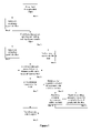
- FIG. 1 depicts a flow chart illustrating some of the possible embodiments of the method of the present invention.
- FIG. 1 is a flow chart depicting possible embodiments of the method of the present invention.
- the method begins, as indicated by Box 1 , by flowing a fluid to be treated through a it object such as, but not limited to an inlet pipe.
- the fluid to be treated then flows through an opening connecting the first object and a second object, as indicated by Box 3 , wherein the second object possesses a cross-sectional area greater than that of the opening between the first object and second object such as a tank.
- Laminar flow is then established within the fluid by allowing the fluid to flow through the second object a sufficient distance such that any turbulence within the fluid dissipates, as indicated by Box 6 .
- Establishing laminar flow in the fluid after the fluid enters the second object can be accomplished by allowing the fluid to flow a distance at least approximately equal to the greatest height of the opening connecting the first object to the second object. Placing the opening of the first object at or near the base of the second object may further assist in establishing laminar flow.
- the fluid is exposed to ultrasonic waves that are transverse or not parallel to the primary flow of fluid through the second object, as indicated by Box 7 .
- the ultrasonic waves emitted into the fluid may be a particular amplitude and/or frequency or range of amplitudes and/or frequencies.
- fluid flow through the tank it may pass through discrete zones in which ultrasonic waves of a particular amplitude and/or frequency or ultrasonic waves ranging in amplitude and/or frequency are emitted into the fluid.
- the fluid then flows from the second object into a third object such as, but not limited to an outlet pipe, as indicated by Box 8 , from which it may collected and/or re-circulated through the second object.
- the fluid should travel a distance with the second object at least approximately equal to twice the greatest height of the opening between first object and second object.
- an agent catalyzing the intended treatment of the fluid such as, but not limit to, chlorine, ozone, peroxide, ultraviolet light, an enzyme, and/or an organism may be introduced into the fluid, as indicated by Box 2 .
- a catalyzing agent may be introduced into the fluid as it flows through the second object, as indicated by Box 4 .
- the matter and/or organism within the fluid Prior to the fluid exiting the second object, the matter and/or organism within the fluid may be allowed to segregate into discrete laminas, as indicated by Box 9 .
- Laminas containing the segregated matter may then be collected by the third object oriented with respect to the second object such that the intended laminas to be collected flow into the third object.
- the segregated matter and/or organisms may be remixed by creating turbulences within the fluid, as indicated by Box 10 .
- the segregated matter and/or organisms may be remixed by emitting ultrasonic waves into the fluid that are not parallel to the force of gravity acting on the matter and/or organism within the fluid, as indicated by Box 11 .
- the fluid may then be re-exposed to ultrasonic waves and/or allowed to flow a sufficient distance such that laminar flow, if destroyed, is allowed to be reestablished in the fluid.
- Ensuring the proper flow of fluid through the second object may be accomplished by, setting the aggregate pressure of fluid entering the second object equal to the aggregate pressure of the fluid exiting second object.
- Positioning the opening the first object into the second object directly opposite the opening of the second object into the third object may assist in establishing the proper flow of fluid through the second object.
- a device employing the method of the present invention is disclosed in U.S. patent application Ser. No. 11/562,343, filed Nov. 21, 2006, the teachings of which are hereby incorporated by reference.
Abstract
Description
- The present invention relates to a method of treating a continuous flow fluid that may be used to degrade matter within fluids, remove matter from fluids, separate matter within a fluid by density, sterilize fluids, and/or degrade toxic chemicals within a fluid.
- The method of the present invention may also be utilized to clean, sterilize, and/or deodorize objects submerged within a continuous flow of fluid.
- Subjecting a fluid to ultrasonic waves enables various treatments of the fluid and objects or matter within the fluid. For instance, submerging objects within a fluid subjected to ultrasonic waves can clean the objects. Placing a piece of solid matter such as, but not limited to, a salt pellet within a fluid subjected to ultrasonic waves causes erosion of the solid matter. Furthermore, matter bonded together may be separated when placed within a fluid subjected to ultrasonic waves. Ultrasonic waves traveling within a fluid may also be utilized to separate matter within fluid into bands or laminas.
- Emitting ultrasonic waves into a fluid induces cavitations, small bubbles, within the fluid and causes objects and/or matter within the fluid to vibrate. As the ultrasound waves pass through the fluid, cavitations are spontaneously formed within the fluid. Explosion of the cavitations creates tiny areas of high pressure within the fluid Releasing high pressure into the fluid, the explosions of the cavitations provide the energy needed to treat the fluid and objects or matter within the fluid. In addition to creating cavitations, ultrasound waves emitted into a fluid vibrate matter and/or objects within the fluid. As matter and/or objects within the fluid vibrate, bonds holding the matter together and/or bond holding matter to an object weaken and sheer.
- Ultrasonic waves emitted into a fluid in which an object is submerged remove matter from the object, thereby cleaning the object. Methods of utilizing ultrasonic, waves emitted into a fluid to clean objects within the fluid are employed by the devices disclosed in U.S. Patent Publication 2006/0086604 AI, U.S. Patent Publication 2005/0220665 AI, and U.S. Pat. No. 6,858,181 B2.
- Trapping energy within cavitations, releasing energy from the explosions of cavitations, and/or inducing vibrations within matter, ultrasonic waves emitted into a fluid sheer the bonds holding matter together such as, but not limited to, adhesive bonds, mechanical bonds, ionic bonds, covalent bonds, and/or van der Waals bonds, thereby separating the matter. Ultrasonic waves passing through the fluid induce vibrations in matter within the fluid. As the matter vibrates, the bonds holding the matter together begin to stretch and sheer weakening, if not breaking, the bonds. Furthermore, matter within and/or near an exploding cavitation is exposed to tremendous changes in pressure that weakens, if not breaks, the bonds. Eventually the bonds holding the matter together become so weakened and strained that they break releasing small pieces and/or molecules of the matter into the fluid. If the matter is comprised of several different substances, the different substances comprising the matter become separated and released into the fluid. Methods of utilizing ultrasonic waves emitted into a fluid to break up and/or separate matter within the fluid are employed by the devices described in U.S. Patent Publication 2003/0183798 AI, U.S. Patent Publication 2003/0051989 AI, and U.S. Pat. No. 6,228,273 BI.
- After matter within a fluid has been separated by ultrasonic waves emitted into the fluid, the matter may segregate into laminas. Segregation of matter within the fluid into laminas is assisted by the ultrasonic waves emitted into the fluid. Striking the matter the ultrasonic waves cause the matter to move through the fluid and into a particular lamina. The particular lamina that matter segregates into is dependent upon, among other things, the density of the matter. Less dense matter such as, but not limited to, gases move towards the upper lamina within the fluid. The movement of gases towards the upper lamina is driven by the ultrasonic waves colliding with the gas molecules as well as the natural tendency of matter less dense than the fluid it is in to move out of the fluid. Denser matter such as, but not limited to, solids and dense fluids, fall out of the fluid. As with less dense matter, ultrasonic waves striking dense manner exert a force on the matter in the direction the ultrasonic waves are traveling through the fluid. However, the force exerted by the ultrasonic waves on dense matter is insufficient to overcome dense matter's natural tendency to sink within the fluid. Consequently, dense matter separated from lighter matter segregates in lower laminas within the fluid. Below the laminas comprising less dense matter and above the laminas comprising dense matter, laminas containing matter of an intermediate density may form. As with dense matter and less dense matter, ultrasonic waves striking matter of an intermediate density exert a force on the matter. Unlike with dense matter, the force exerted by ultrasonic waves bitted into the fluid on matter of an intermediate density counteracts in whole or in part the natural tendency of the intermediate dense matter to sink. The more dense the matter the less effective the ultrasonic waves are at counteracting the matter's tendency to sink. Consequently, the matter will segregate into laminas based on, among other things, the density of the matter. A method of utilizing ultrasonic waves emitted into fluid to separate matter within a fluid into laminas based on density is employed by the device disclosed in U.S. Pat. No. 6,929,750 B2.
- The breaking of bonds with ultrasonic waves emitted into a fluid can also be utilized to kill and/or inactivate organisms within the fluid such as, but not limited to, bacteria, viruses, fungi, algae, and/or yeast. Separating the molecules making up an organism's cellular membranes vibrations and cavitations create holes within an organism's cellular membranes. Chemicals may enter and/or leave the organism's cytoplasm through the holes created in the cellular membranes causing the cell to lyse and/or become poisoned. In addition to disrupting cellular membranes, ultrasonic waves emitted into a fluid may also denature or otherwise damage molecules needed by the organism for survival. For example, by inducing a protein within an organism to vibrate ultrasonic waves emitted into a fluid containing the organism may cause the subunits comprising the protein to separate. Denaturing a protein renders the protein ineffective in its life sustaining role, thereby essentially removing the protein from the organism. Loss of the protein may inactivate the organism and/or eventually lead to the organism's death, if the protein is needed for survival. Methods of utilizing ultrasonic waves emitted into a fluid to inactivate and/or kill organisms are employed by the devices disclosed in U.S. Patent Publication 2003/0234173 AI, U.S. Pat. No. 7,018,546 82, and U.S. Pat. No. 6,444,176 B1.
- Though there are methods of utilizing ultrasonic waves emitted into a fluid to clean objects within the fluid, sterilize the fluid and/or objects within it, separate bonded matter within the fluid, segregate matter within the fluid into discrete laminas, and kill and/or inactivate organisms within the fluid, a method providing all of the these treatments on a large scale is lacking.
- The present invention relates to a method of utilizing ultrasonic waves emitted into a fluid to treat the fluid, matter within the fluid, and/or organisms within the fluid in a variety of manners such as, but not limited to, cleaning objects within the fluid, sterilizing the fluid and/or objects within it, separating bonded matter within the fluid, segregating matter within the fluid into discrete laminas, killing organisms within the fluid, inactivating organisms within the fluid, extracting matter from organisms within the fluid, extracting matter from other matter within the fluid, inducing chemical reactions within the fluid, and/or converting toxic matter within the fluid into a less toxic state.
- The method of the present invention comprises the steps of flowing the fluid to be treated, which may contain matter and/or organisms to be treated, through an object or plurality of objects such as, but not limited to a pipe, emptying the fluid flowing through the first object into an second object or plurality of second objects such as, but not limited to, a tank, wherein each second object possesses a cross-sectional area larger than the opening between the first objects and second objects, emitting ultrasonic waves into the fluid that are transverse or not parallel to the primary flow of fluid through the second objects as it flows through the second objects, establishing laminar flow in the fluid as the fluid flows through the second objects, and collecting the fluid in a third object or plurality of third objects such as, but not limited to, pipes.
- The openings between the first objects feeding fluid into the second objects should, have a cross-sectional area smaller than that of the second objects. When the fluid to be treated enters second objects, the velocity of the fluid decreases while the overall rate of flow (volume of fluid passing through the first and second object and into the third object per unit time) remains constant. The reduced velocity of the fluid within the second objects increases the amount of treatment received by each volume of fluid passing through the second objects by increasing the amount of time the fluid, matter within the fluid, and/or organisms within the fluid are exposed to ultrasonic waves. The increased exposure to ultrasonic waves may help to increase the efficacy of the ultrasonic treatment.
- In certain situations, it may be desirable to establish laminar flow in the fluid prior to exposing the fluid, matter within the fluid, and/or organisms within the fluid to ultrasonic waves. Establishing laminar flow in the fluid helps to ensure the creation of stable cavitations and/or ultrasonic waves within the fluid. Utilizing laminar flow to create stable cavitations and/or ultrasonic waves within the fluid may increase the efficacy of the treatment of the fluid, matter within the fluid, and/or organisms within the fluid by ultrasonic waves emitted into in the fluid. Creating a laminar flow in the fluid as the fluid flows through the second object entails allowing the fluid to flow a sufficient distance such that any turbulences created in the fluid from the fluid's entry into the second objects, the fluid's collision with obstructions within the second objects, and/or the fluid's collision with the walls of the second objects dissipate before the fluid exits the second object.
- As to help establish laminar flow within the fluid prior to reaching the first element emitting ultrasonic waves into the fluid such as, but not limited to, a Langevin ultrasound transducer or a cymbal ultrasound transducer the first element emitting ultrasonic waves into the fluid within the second object, with respect to the flow of fluid through the second object, should be located at a distance from the point of the second object at which fluid enters from the first objects that is at least approximately equal to the greatest height of the openings of the first objects into the second objects. The length of the second objects with respect to the flow of fluid through the second objects should be at least approximately equal to twice the greatest height of the openings of the first objects into the second objects.
- Determining if a particular configuration allows for the creation of a laminar flow of the fluid through the second objects can be determined by observing fluid flowing through the second objects. Observing fluid flow through a particular configuration can be accomplished by constructing a transparent mock up of the intended configuration. A fluid containing fine particles suspended within the fluid can then be flowed through the transparent mock up.
- The elements emitting ultrasonic waves into the fluid that are not parallel to the primary flow, overall direction of flow, of fluid through the second objects may be located within any sidewall and/or similar structure the second objects may possess. A sidewall is any wall and/or similar structure of the second objects that is not orientated perpendicular to the primary flow of fluid through the second objects.
- Any given element emitting ultrasonic waves into the fluid as the fluid flows through the second objects may emit ultrasonic waves of a particular frequency and/or amplitude or may emit ultrasonic waves varying in frequency and/or amplitude. The frequency of the ultrasonic waves emitted should be at least approximately 18 kHz. Preferably the ultrasonic waves emitted into the fluid as the fluid flows through the second objects possess a frequency between approximately 20 kHz and approximately 200 kHz or between approximately 1 MHz and approximately 5 MHz. The amplitude of the ultrasonic waves emitted into the fluid should be at least approximately 1 micron or greater.
- Every volume of fluid passing through the second objects should be exposed to ultrasonic waves of each frequency and/or amplitude emitted into the fluid for at least one second. Preferably, every gallon of fluid to be treated should be exposed to ultrasonic waves of each frequency and/or amplitude emitted into the, fluid for approximately 5 seconds. A discrete element may be responsible for emitting ultrasonic waves of a particular frequency and/or amplitude or range of frequencies and/or amplitudes into the flowing fluid. Alternatively, the elements emitting ultrasonic waves into the fluid may be arranged such that fluid is exposed zones of ultrasonic waves of a particular frequency and/or amplitude or range of frequencies and/or amplitudes.
- Creating zones of ultrasonic waves may be accomplished by arranging the ultrasonic emitting elements into bands and/or arrays of bands responsible for emitting ultrasonic waves of a particular frequency and/or amplitude or range of frequencies and/or amplitudes into the fluid. Arranging the elements responsible for emitting ultrasonic waves of a particular frequency and/or amplitude or range of frequencies and/or amplitudes into bands and/or arrays of bands helps enable the creation of stable cavitations and/or ultrasonic waves of the desired frequencies and/or amplitudes within the fluid as the fluid flows through the second objects.
- The elements releasing ultrasonic waves into the fluid may be activated simultaneously. Alternatively, the ultrasound releasing elements, bands, and/or arrays of bands may be activated sequentially such that an element, band, and/or array is activated when the preceding transducer, band, and/or array, with respect to the flow of fluid, is deactivated. The elements emitting ultrasonic waves may be driven by a variety of wave patterns such as, but not limited to, square, triangle, trapezoidal, sinusoidal, and/or any combination thereof.
- The intensity of the ultrasound energy released by the ultrasound emitting elements required to treat the fluid as the fluid flows through the second objects is dependent on the depth of the fluid above the emitting element. The intensity required for a particular depth can be determined by placing the desired depth of fluid over an emitting element. Ultrasound energy of an ever increasing intensity can then be emitted from the element while the surface of the fluid over the element is monitored. When the desired treatment of fluid is observed at the surface of the fluid, the intensity of the ultrasound energy released into the fluid should be noted and recorded, as it corresponds to the intensity required for the given depth of fluid. If the emitting elements are oriented such that the ultrasonic waves emitted into the fluid intersect at an angle less than 180 degrees, then the above procedure should be performed with a depth of fluid equal to the maximum distance from the emitting elements to the point of intersection of the ultrasonic waves. If the ultrasonic waves emitted into the fluid from multiple emitting elements intersect at a 180 degree angle, then the above procedure should be performed with a depth of fluid equal to half the distance between the emitting elements.
- Emitting ultrasonic waves of varying frequencies and/or amplitudes helps to enable treatment of fluids containing various matter and/or organisms. As the fluid flows through the second object, a laminar flow may be established prior to reaching the first element emitting ultrasonic waves into the fluid. The ultrasonic waves emitted into the fluid induce cavitations within fluid and/or vibrations within any matter and/or organism within the fluid. The energy released by cavitations within the fluid and the vibrations, if any, induced within any matter and/or organism present in the fluid depends upon the frequency and/or amplitude of the ultrasonic waves passing through the fluid.
- Different matter and/or organisms within fluid may be sensitive to ultrasonic waves of different frequencies and/or amplitudes. Exposing matter to ultrasonic waves of the proper frequency induces resonating vibrations within the matter. Resonating vibrations place the greatest amount of strain on the bonds within the matter, thereby making them more likely to break spontaneously and/or break when exposed to the energy released from the exploding cavitations. Likewise, the membranes and/or molecules of different organisms will vibrate in resonance when exposed to ultrasonic waves of a particular frequency and/or amplitude thereby making the organism's membranes more likely to rupture spontaneously and/or when exposed to the energy released from the exploding cavitations. Inducing resonating vibrations within the molecules of an, organism makes the organism's molecules more likely to denature spontaneously and/or when exposed to the energy released from the exploding cavitations.
- As the cells and/or viruses within the fluid stream rupture, matter within the cells and/or viruses such as, but not limited to, proteins, nucleic acids, and/or sugars, are released into the fluid. Matter released from organisms within the fluid is then free to segregate into laminas. Segregation of material into different laminas of the fluid may be most efficient within regions of laminar fluid flow. Likewise, molecules released from the erosion of matter and/or from the breaking of bonds within the matter are free to segregate into laminas when separated. The laminas within the fluid may be collected with different third objects into which the fluid to be treated flows after leaving the second objects.
- For example, it may be desirable to collect dense matter located within the lower laminas with an outlet pipe or similar collecting third objects located near the bottom of the second objects. The collected dense matter may be re-circulated through the second objects as to expose the matter to further treatment. Exposing the matter to several treatments within the second objects may allow more matter of a lesser density to be separated from the denser matter and/or segregate into higher laminas within the fluid. Less dense matter located within the upper laminas may be collected with an outlet pipe located near the top of the second object. Alternatively, volatile matter segregating a into the upper lamina of the fluid may be allowed to escape from the fluid through an open top of second objects and/or a porous material covering the second objects. Matter of an intermediate density segregating into middle laminas may be collected with an outlet pipe or similar collecting third objects located near the middle of the second objects. The fluid and/or laminas recovered from the second objects by the collecting third objects may be discharged and/or retained for further processing.
- Disrupting the established laminar flow of fluid during treatment may be desirable. For instance disrupting laminar flow by creating turbulences such as, but not limited to, vortices, burbles, eddies, and/or any combination thereof may allow matter segregated into discrete laminas to be remixed. Matter within laminas not disturbed by the turbulences, however, will remain segregated. Combining matter from an upper lamina and a lower lamina may be accomplished by creating a vortex within the fluid. Spiraling downward, the vortices pull matter from laminas along the length of the vortices downward to lower laminas. Creating a vortex within the fluid as the fluid flows through the second objects can be accomplished by placing an outlet or plurality of outlets in the lower portion of the second objects.
- Combining matter from adjacent laminas may be accomplished by creating eddies at the boundary of two or more laminas. The turbulence created by the eddy may pull matter from upper laminas into the lower laminas and matter from the lower laminas into the upper laminas. Creating an eddy at the upper and lower boundaries of a lamina may allow material from both lamina above and below to be pulled into the middle lamina. Eddies can be created by placing obstructions in the path of the fluid's flow through the second objects that the fluid cannot smoothly flow around such as, but not limited to, rectangular prisms and/or triangular prisms. Alternatively, material from several adjacent laminas may be combined by creating large burbles within the second objects that span several laminas. Creating a burble can be accomplished by placing an airfoil like structure in the path of the fluid that is angled with respect to the flow of fluid striking the airfoil. Turbulence disrupting laminar flow may also be created by injecting fluid into the second objects.
- Remixing matter segregated into laminas may also be accomplished with ultrasonic waves emitted into the fluid. Emitting ultrasonic waves into the fluid that are transverse or not parallel to the force of gravity acting on the matter within the fluid may carry matter out of a lamina into which the matter has segregated and into other laminas. As ultrasonic waves not parallel to the force of gravity acting on the matter within the fluid pass through the fluid, the ultrasonic waves may direct matter within the fluid that is along the waves' path to anti-nodal points of the waves. If the ultrasonic waves not parallel to the force of gravity acting on the matter within the fluid span multiple laminas, then matter within one lamina may be carried to the laminas encompassing anti-nodal points of the wave. Emitting ultrasonic waves into the fluid that are not parallel to the force of gravity acting on matter within the fluid may be accomplished with ultrasonic emitting elements located within sidewalls or similar structures of the second objects and/or located within walls or similar structures of the second objects approximately perpendicular to the primary flow of fluid through the second objects.
- Selectively mixing material segregated into laminas may be desirable if chemical reactions are to take place within the fluid. For instance, matter within the fluid may react to form a desired product. However, formation of the desired product may be hindered by the presence of other matter within the fluid. The other matter may be a separate reagent, a product of the reaction producing the desired product, and/or the desired product itself. The other matter may react with the reagents producing the desired product thereby preventing the production of the desired product. Alternatively, reacting with the desired product, the other matter may convert the desired product into an undesired product.
- Segregating the reagents, desired product, and/or other matter into discrete laminas and then selectively recombining the laminas prevents other matter that hinders and/or prevents the formation of the desired product from reacting with the reagents producing the desired product and/or from reacting with the desired product. Similarly, segregating the reagents, desired product, and/or other matter into discrete laminas allows optimization of desired chemical reactions.
- Thus, after a chemical reaction occurring within and/or outside the second objects, a laminar flow of fluid may be established within the fluid flowing through the second objects. The matter within the fluid may then be allowed to segregate into discrete laminas. Selectively remixing laminas containing matter that reacts to produce the desired product and/or another desired reaction may then be accomplished by creating turbulences within the fluid and/or remixing the lamina outside of the second objects. Following and/or during the selective remixing of the laminas, the matter within the combined laminas may then be allowed to react within and/or outside the second objects. Serially segregating, recombining, and/or reacting the matter within the fluid may be done with one configuration of first, second, and third objects and/or within several such configurations connected in series and/or in parallel.
- Reactions occurring within the second objects may be catalyzed by a variety of catalyzing agents, such as, but not limited, chemicals, microorganisms, enzymes, radio waves, microwaves, light waves, and/or any combination thereof introduced into the fluid while and/or prior to the fluid flowing through the second objects. For instance, prior to the fluid entering the tank from the first objects, a chemical such as, but not limited to, chlorine, bromine, ozone, antibiotic, antifungal, antiviral, and/or any combination thereof, may be introduced into the fluid. The introduced chemical may react with fluid, with matter within the fluid, and/or with organism within the fluid as to bring about a desired result. For instance, the chemical may react with matter within the fluid as to transform the matter into a less toxic state. Alternatively, the chemical may react with organisms within the fluid as to kill and/or inactivate the organisms. The energy within and/or released from cavitations within the fluid and/or vibrations of matter and/or organisms within the fluid may increase the efficacy and/or rate of the chemical reaction.
- Accordingly, one aspect of the present invention to may be to provide a method of cleaning objects submerged in a flowing fluid.
- Another aspect of the present invention may be to provide a method of sterilizing objects submerged in a flowing fluid.
- Another aspect of the present invention may be to provide a method of deodorizing objects submerged in a flowing fluid.
- Another aspect of the preset invention may be to provide a method of sterilizing a flowing fluid flowing.
- Another aspect of the present invention may be to provide a method of inactivating organisms within a flowing fluid.
- Another aspect of the present invention may be to provide a method of killing organisms within a flowing fluid.
- Another aspect of the present invention may be to provide a method of deodorizing a flowing fluid.
- Another aspect of the present invention may be to provide a method of separating bonded matter within a flowing fluid.
- Another aspect of the present invention may be to provide a method of releasing matter within organisms within a flowing fluid.
- Another aspect of the present invention may be to provide a method of segregating matter within a flowing fluid flowing into laminas.
- Another aspect of the present invention may be to provide a method of converting toxic matter within a flowing fluid into a less toxic state.
- Another aspect of the present invention may be to provide a method of removing gases from the flowing fluid.
- Another aspect of the present invention may be to provide a method of extracting matter from a combination of matter within a flowing fluid.
- Another aspect of the present invention may be to provide a method of extracting matter from cells within a flowing fluid.
- Another aspect of the present invention may be to provide a method of extracting matter from viruses with a flowing fluid.
- These and other aspects of the invention will become more apparent from the written description and figures below.
- The present invention will be shown and described with reference to the drawings of preferred embodiments and clearly understood in detail.
-
FIG. 1 depicts a flow chart illustrating some of the possible embodiments of the method of the present invention. -
FIG. 1 is a flow chart depicting possible embodiments of the method of the present invention. The method begins, as indicated byBox 1, by flowing a fluid to be treated through a it object such as, but not limited to an inlet pipe. The fluid to be treated then flows through an opening connecting the first object and a second object, as indicated byBox 3, wherein the second object possesses a cross-sectional area greater than that of the opening between the first object and second object such as a tank. Laminar flow is then established within the fluid by allowing the fluid to flow through the second object a sufficient distance such that any turbulence within the fluid dissipates, as indicated byBox 6. Establishing laminar flow in the fluid after the fluid enters the second object can be accomplished by allowing the fluid to flow a distance at least approximately equal to the greatest height of the opening connecting the first object to the second object. Placing the opening of the first object at or near the base of the second object may further assist in establishing laminar flow. Before leaving the second object, the fluid is exposed to ultrasonic waves that are transverse or not parallel to the primary flow of fluid through the second object, as indicated byBox 7. The ultrasonic waves emitted into the fluid may be a particular amplitude and/or frequency or range of amplitudes and/or frequencies. With respect to the latter, as fluid flow through the tank it may pass through discrete zones in which ultrasonic waves of a particular amplitude and/or frequency or ultrasonic waves ranging in amplitude and/or frequency are emitted into the fluid. The fluid, then flows from the second object into a third object such as, but not limited to an outlet pipe, as indicated byBox 8, from which it may collected and/or re-circulated through the second object. Before entering the third the object, the fluid should travel a distance with the second object at least approximately equal to twice the greatest height of the opening between first object and second object. - In some situations, it may be desirable to emit ultrasonic waves into regions of the fluid not in laminar flow within the second object, as indicated by
Box 5. - In keeping with
FIG. 1 , before the fluid enters the second object, an agent catalyzing the intended treatment of the fluid such as, but not limit to, chlorine, ozone, peroxide, ultraviolet light, an enzyme, and/or an organism may be introduced into the fluid, as indicated byBox 2. Alternatively and/or in addition to, a catalyzing agent may be introduced into the fluid as it flows through the second object, as indicated byBox 4. - Prior to the fluid exiting the second object, the matter and/or organism within the fluid may be allowed to segregate into discrete laminas, as indicated by
Box 9. Laminas containing the segregated matter may then be collected by the third object oriented with respect to the second object such that the intended laminas to be collected flow into the third object. Alternatively, the segregated matter and/or organisms may be remixed by creating turbulences within the fluid, as indicated byBox 10. Alternatively, the segregated matter and/or organisms may be remixed by emitting ultrasonic waves into the fluid that are not parallel to the force of gravity acting on the matter and/or organism within the fluid, as indicated byBox 11. The fluid may then be re-exposed to ultrasonic waves and/or allowed to flow a sufficient distance such that laminar flow, if destroyed, is allowed to be reestablished in the fluid. - Ensuring the proper flow of fluid through the second object may be accomplished by, setting the aggregate pressure of fluid entering the second object equal to the aggregate pressure of the fluid exiting second object.
- Positioning the opening the first object into the second object directly opposite the opening of the second object into the third object may assist in establishing the proper flow of fluid through the second object. A device employing the method of the present invention is disclosed in U.S. patent application Ser. No. 11/562,343, filed Nov. 21, 2006, the teachings of which are hereby incorporated by reference.
- Although specific embodiments have been illustrated and described herein, it will be appreciated by those of ordinary skill in the art that any arrangement that is calculated to achieve the same or similar purpose may be substituted for the specific embodiments disclosed. It is to be understood that the above description is intended to be illustrative and not restrictive. Alternative combinations of the step of the disclosed embodiments and other embodiments will be apparent to those having skill in the art upon review of the present disclosure. The scope of the present invention should be determined with reference to the appended claims, along with the full scope of equivalents to which such claims are entitled.
- The method of action of the present invention and prior art devices presented herein are based solely on theory. They are not intended to limit the method of action of the present invention or exclude of possible methods of action that may be present within the present invention and/or responsible for the actions of the present invention.
Claims (25)
Priority Applications (1)
| Application Number | Priority Date | Filing Date | Title |
|---|---|---|---|
| US11/566,681 US7846341B2 (en) | 2006-12-04 | 2006-12-04 | Method of ultrasonically treating a continuous flow of fluid |
Applications Claiming Priority (1)
| Application Number | Priority Date | Filing Date | Title |
|---|---|---|---|
| US11/566,681 US7846341B2 (en) | 2006-12-04 | 2006-12-04 | Method of ultrasonically treating a continuous flow of fluid |
Publications (2)
| Publication Number | Publication Date |
|---|---|
| US20080128362A1 true US20080128362A1 (en) | 2008-06-05 |
| US7846341B2 US7846341B2 (en) | 2010-12-07 |
Family
ID=39494264
Family Applications (1)
| Application Number | Title | Priority Date | Filing Date |
|---|---|---|---|
| US11/566,681 Active - Reinstated 2029-09-27 US7846341B2 (en) | 2006-12-04 | 2006-12-04 | Method of ultrasonically treating a continuous flow of fluid |
Country Status (1)
| Country | Link |
|---|---|
| US (1) | US7846341B2 (en) |
Cited By (6)
| Publication number | Priority date | Publication date | Assignee | Title |
|---|---|---|---|---|
| US20140054173A1 (en) * | 2011-01-17 | 2014-02-27 | Aage Bjorn Andersen | Electrodialysis unit for water treatment |
| CN103979636A (en) * | 2014-06-04 | 2014-08-13 | 哈尔滨工业大学 | Method for enhanced degradation of antibiotics in sewage by combination of ultrasound/ozone |
| WO2015056003A3 (en) * | 2013-10-14 | 2015-06-11 | Coldharbour Marine Limited | Apparatus and method using ultrasounds for gas conversion |
| US9359232B2 (en) | 2011-01-17 | 2016-06-07 | Oceansaver As | Electrodialysis unit for water treatment |
| US9561971B2 (en) | 2011-01-17 | 2017-02-07 | Oceansaver As | Electrodialysis unit for water treatment |
| WO2024038366A1 (en) * | 2022-08-15 | 2024-02-22 | Ozono Polaris, S.A. de C.V. | Ultrasonic devices and methods for regeneration of activated carbon |
Families Citing this family (4)
| Publication number | Priority date | Publication date | Assignee | Title |
|---|---|---|---|---|
| WO2013067041A1 (en) | 2011-11-01 | 2013-05-10 | Indrani Deo | Dispensing nozzle with an ultrasound activator |
| US10786801B2 (en) | 2016-11-22 | 2020-09-29 | Khalifa University of Science and Technology | Continuous sono-chemical reactors and methods of using the same |
| US11009764B2 (en) * | 2018-01-02 | 2021-05-18 | Intel Corporation | Head mounted display including variable beam divergence and/or beam direction |
| US11732927B2 (en) * | 2020-04-09 | 2023-08-22 | Rheem Manufacturing Company | Systems and methods for preventing and removing chemical deposits in a fluid heating device |
Citations (70)
| Publication number | Priority date | Publication date | Assignee | Title |
|---|---|---|---|---|
| US3708263A (en) * | 1971-01-15 | 1973-01-02 | Wave Energy Systems | Method for continuous sterilization at low temperature |
| US4086057A (en) * | 1976-07-28 | 1978-04-25 | William Clinton Everett | Ultrasonic disinfection system |
| US4111744A (en) * | 1974-03-14 | 1978-09-05 | Reiniger Haigh M | Process for producing fused cellulose products |
| US4168295A (en) * | 1975-11-20 | 1979-09-18 | Vernon D. Beehler | Apparatus for enhancing chemical reactions |
| US4599459A (en) * | 1984-08-31 | 1986-07-08 | Masanao Hirose | Method for the ultrasonic treatment of a dilute alcoholic solution |
| US4747920A (en) * | 1984-06-20 | 1988-05-31 | Battelle Memorial Institute | Solid-liquid separation process for fine particle suspensions by an electric and ultrasonic field |
| US5076266A (en) * | 1989-04-14 | 1991-12-31 | Azerbaidzhansky Politekhnichesky Institut Imeni Ch. Ildryma | Device for ultrasonic atomizing of liquid medium |
| US5124050A (en) * | 1989-11-22 | 1992-06-23 | Kabushiki Kaisha Toshiba | Method and apparatus for removing hypochlorous acid components from apparatus for processing tap water |
| US5402965A (en) * | 1993-09-20 | 1995-04-04 | Rockwell International Corporation | Reusable flyback satellite |
| US5611993A (en) * | 1995-08-25 | 1997-03-18 | Areopag Usa, Inc. | Ultrasonic method of treating a continuous flow of fluid |
| US5738824A (en) * | 1994-11-11 | 1998-04-14 | Netzsch Newamatic Gmbh | Method for the testing and cleaning of instruments for minimal invasive surgery or minimal invasive examination of body cavities |
| US5779985A (en) * | 1995-12-18 | 1998-07-14 | Solid Phase Sciences Corporation | Reaction plenum |
| US5783790A (en) * | 1995-11-30 | 1998-07-21 | Organo Corporation | Wet treatment method |
| US5807521A (en) * | 1994-11-14 | 1998-09-15 | Siemens Aktiengesellschaft | Method and apparatus for cleaning and sterilizing a dental apparatus |
| US5811993A (en) * | 1996-10-04 | 1998-09-22 | International Business Machines Corporation | Supply voltage independent bandgap based reference generator circuit for SOI/bulk CMOS technologies |
| US5858534A (en) * | 1995-09-05 | 1999-01-12 | Solid Phase Sciences Corp. | Method of making and using derivatized paramagnetic polymer beads |
| US5876877A (en) * | 1990-12-28 | 1999-03-02 | Fujitsu Limited | Patterned mask having a transparent etching stopper layer |
| US5876671A (en) * | 1993-03-24 | 1999-03-02 | The Regents Of The University Of California Office Of Technology Transfer | Sonication standard laboratory module |
| US5879257A (en) * | 1996-02-20 | 1999-03-09 | Tsubakimoto Chain Co. | Chain having seal with annular sealing projection |
| US5951456A (en) * | 1997-05-16 | 1999-09-14 | Scott; Harold W. | Ultrasonic methods and apparatus for separating materials in a fluid mixture |
| US5958228A (en) * | 1995-08-24 | 1999-09-28 | Nippondenso Co., Ltd. | Method of and an apparatus for producing a mineral water |
| US6214222B1 (en) * | 1998-07-06 | 2001-04-10 | Ulrich Gerber | Method and apparatus for treating liquid |
| US6228273B1 (en) * | 1998-08-21 | 2001-05-08 | Hammonds Technical Services, Inc. | Apparatus and method for control of rate of dissolution of solid chemical material into solution |
| US6245207B1 (en) * | 1998-05-20 | 2001-06-12 | Hitachi, Ltd. | Cell separation device using ultrasound and electrophoresis |
| US20010053384A1 (en) * | 1997-07-07 | 2001-12-20 | James F. Greenleaf | Site-directed transfection with ultrasound and cavitation nuclei |
| US6395096B1 (en) * | 1999-01-21 | 2002-05-28 | Uncopiers, Inc. | Single transducer ACIM method and apparatus |
| US20020082666A1 (en) * | 2000-12-22 | 2002-06-27 | Eilaz Babaev | Wound treatment method and device with combination of ultrasound and laser energy |
| US20020088705A1 (en) * | 2001-01-06 | 2002-07-11 | Scott Harold W. | Method and apparatus for treating fluids |
| US20020103448A1 (en) * | 2001-01-30 | 2002-08-01 | Eilaz Babaev | Ultrasound wound treatment method and device using standing waves |
| US6444176B1 (en) * | 1997-08-20 | 2002-09-03 | Marine Techno Research, Inc. | Apparatus for purification of water area |
| US20020138036A1 (en) * | 2001-03-21 | 2002-09-26 | Eilaz Babaev | Ultrasonic catheter drug delivery method and device |
| US20020156400A1 (en) * | 2001-04-23 | 2002-10-24 | Eilaz Babaev | Ultrasonic method and device for wound treatment |
| US20020159917A1 (en) * | 2001-04-27 | 2002-10-31 | Swart Sally Kay | System and method for cleaning, high level disinfection, or sterilization of medical or dental instruments or devices |
| US20020195402A1 (en) * | 2001-06-22 | 2002-12-26 | Minter Bruce E. | Method and apparatus for treating fluid mixtures with ultrasonic energy |
| US20030019791A1 (en) * | 2001-06-18 | 2003-01-30 | Petronetics, Llc. | Method to upgrade hydrocarbon mixtures |
| US20030042174A1 (en) * | 2001-06-18 | 2003-03-06 | Petronetiics Llc. | Method to treat emulsified hydrocarbon mixtures |
| US20030051989A1 (en) * | 2001-06-18 | 2003-03-20 | Petronetics, Llc. | Method to liberate hydrocarbon fractions from hydrocarbon mixtures |
| US20030051988A1 (en) * | 2001-05-22 | 2003-03-20 | Gunnerman Rudolf W. | Treatment of crude oil fractions, fossil fuels, and products thereof with ultrasound |
| US6569099B1 (en) * | 2001-01-12 | 2003-05-27 | Eilaz Babaev | Ultrasonic method and device for wound treatment |
| US6601581B1 (en) * | 2000-11-01 | 2003-08-05 | Advanced Medical Applications, Inc. | Method and device for ultrasound drug delivery |
| US20030153961A1 (en) * | 2000-12-22 | 2003-08-14 | Eilaz Babaev | Wound treatment method and device with combination of ultrasound and laser energy |
| US20030171701A1 (en) * | 2002-03-06 | 2003-09-11 | Eilaz Babaev | Ultrasonic method and device for lypolytic therapy |
| US6649069B2 (en) * | 2002-01-23 | 2003-11-18 | Bae Systems Information And Electronic Systems Integration Inc | Active acoustic piping |
| US20030236560A1 (en) * | 2001-01-12 | 2003-12-25 | Eilaz Babaev | Ultrasonic method and device for wound treatment |
| US20030234173A1 (en) * | 2002-06-20 | 2003-12-25 | Minter Bruce E. | Method and apparatus for treating fluid mixtures with ultrasonic energy |
| US20040030254A1 (en) * | 2002-08-07 | 2004-02-12 | Eilaz Babaev | Device and method for ultrasound wound debridement |
| US20040042936A1 (en) * | 2002-08-28 | 2004-03-04 | Koukichi Ido | Cross-wave sonicator |
| US20040069717A1 (en) * | 2001-03-09 | 2004-04-15 | Thomas Laurell | Device and method for separation |
| US20040079680A1 (en) * | 2002-10-23 | 2004-04-29 | Sulphco., Inc. | Ultrasound-assisted desulfurization of fossil fuels in the presence of dialkyl ethers |
| US20040129643A1 (en) * | 2001-03-13 | 2004-07-08 | Dominique Dubruque | Liquid process and continuous filtering device using high power density ultrasounds |
| US20040159537A1 (en) * | 2002-10-15 | 2004-08-19 | Yasuaki Maeda | Method for producing fatty acid alcohol ester |
| US20040186384A1 (en) * | 2001-01-12 | 2004-09-23 | Eilaz Babaev | Ultrasonic method and device for wound treatment |
| US20040256213A1 (en) * | 2001-07-30 | 2004-12-23 | Evgeny Marhasin | High power ultrasonic reactor for sonochemical applications |
| US6858181B2 (en) * | 2002-01-22 | 2005-02-22 | Kabushiki Kaisha Sunseal | Method for cleaning and sterilizing medical equipment after use |
| US6878286B2 (en) * | 2000-10-25 | 2005-04-12 | Basin Water, Inc. | High efficiency ion exchange system for removing contaminants from water |
| US20050220665A1 (en) * | 2004-04-05 | 2005-10-06 | Ding Lambert L | Low temperature sterilization and disinfections method and apparatus for medical apparatus and instruments |
| US6964647B1 (en) * | 2000-10-06 | 2005-11-15 | Ellaz Babaev | Nozzle for ultrasound wound treatment |
| US7018546B2 (en) * | 2003-03-06 | 2006-03-28 | Hitachi, Ltd. | Water treatment method and water treatment device |
| US20060086604A1 (en) * | 1996-09-24 | 2006-04-27 | Puskas William L | Organism inactivation method and system |
| US20070016110A1 (en) * | 2005-06-23 | 2007-01-18 | Eilaz Babaev | Removable applicator nozzle for ultrasound wound therapy device |
| US20070031611A1 (en) * | 2005-08-04 | 2007-02-08 | Babaev Eilaz P | Ultrasound medical stent coating method and device |
| US20070051307A1 (en) * | 2005-08-16 | 2007-03-08 | Babaev Eilaz P | Ultrasound apparatus and methods for mixing liquids and coating stents |
| US20070088386A1 (en) * | 2005-10-18 | 2007-04-19 | Babaev Eilaz P | Apparatus and method for treatment of soft tissue injuries |
| US20070088217A1 (en) * | 2005-10-13 | 2007-04-19 | Babaev Eilaz P | Apparatus and methods for the selective removal of tissue using combinations of ultrasonic energy and cryogenic energy |
| US20070088245A1 (en) * | 2005-06-23 | 2007-04-19 | Celleration, Inc. | Removable applicator nozzle for ultrasound wound therapy device |
| US20070185527A1 (en) * | 2005-10-18 | 2007-08-09 | Ab Ortho, Llc | Apparatus and method for treating soft tissue injuries |
| US20070233054A1 (en) * | 2005-10-13 | 2007-10-04 | Bacoustics, Llc | Apparatus and methods for the selective removal of tissue |
| US20070231346A1 (en) * | 2006-03-29 | 2007-10-04 | Babaev Eilaz P | Apparatus and methods for vaccine development using ultrasound technology |
| US20070239250A1 (en) * | 2006-03-29 | 2007-10-11 | Eilaz Babaev | Electrodes for transcutaneous electrical nerve stimulator |
| US20070244528A1 (en) * | 2006-04-12 | 2007-10-18 | Eilaz Babaev | Apparatus and methods for pain relief using ultrasound waves in combination with cryogenic energy |
Family Cites Families (16)
| Publication number | Priority date | Publication date | Assignee | Title |
|---|---|---|---|---|
| US4211744A (en) | 1978-05-24 | 1980-07-08 | Biophysics Research & Consulting Corporation | Process for ultrasonic pasteurization |
| AT390739B (en) | 1988-11-03 | 1990-06-25 | Ewald Dipl Ing Dr Benes | METHOD AND DEVICE FOR SEPARATING PARTICLES DISPERSED IN A DISPERSION AGENT |
| JPH03504821A (en) | 1989-03-27 | 1991-10-24 | アゼルバイジャンスキ ポリテフニチェスキ インスティテュト イメニ チェー.イルドリマ | Liquid ultrasonic atomization device |
| GB9006989D0 (en) | 1990-03-28 | 1990-05-23 | Atomic Energy Authority Uk | Sonochemical apparatus |
| US5466367A (en) | 1994-04-06 | 1995-11-14 | Environmental Restoration Services, Inc. | Industrial waste water treatment |
| WO1997017933A1 (en) | 1995-11-15 | 1997-05-22 | Aeropag Usa, Inc. | Method of spraying a surface using ultrasonic radiation |
| FR2742352B1 (en) | 1995-12-18 | 1998-02-27 | Ixtlan Ag | PROCESS AND APPARATUS FOR FILTERING LIQUID OR PASTY SUBSTANCES AND / OR FOR SEPARATING COMPONENTS INCLUDED IN SUCH SUBSTANCES |
| US5876677A (en) | 1996-04-25 | 1999-03-02 | Mensinger; Michael C. | Ultrasound-assisted liquid redox absorber |
| SI9600307A (en) | 1996-10-18 | 1997-04-30 | Marjan Zupancic | Ultrasonic precrystallizer |
| GB9701797D0 (en) | 1997-01-29 | 1997-03-19 | Univ Coventry | Cavitation inducer |
| US6402965B1 (en) | 1999-07-13 | 2002-06-11 | Oceanit Laboratories, Inc. | Ship ballast water ultrasonic treatment |
| JP2005520574A (en) | 2000-09-25 | 2005-07-14 | アドバンスト メディカル アプリケーションズ インコーポレーテッド | Ultrasound method and apparatus for wound treatment |
| DE10050315C2 (en) | 2000-10-10 | 2003-08-21 | Uhde Gmbh | Process for dissolving salts in 1,2-dichloroethane by means of ultrasound and device for carrying out the process |
| ES2199683B1 (en) | 2002-08-01 | 2005-06-01 | Consejo Sup. De Invest. Cientificas | SEPARATION OR EXTRACTION PROCEDURE WITH SUPERCRITICAL FLUIDS ASSISTED BY HIGH INTENSITY ULTRASOUNDS. |
| US6878288B2 (en) | 2002-12-17 | 2005-04-12 | Harold W. Scott | System and apparatus for removing dissolved and suspended solids from a fluid stream |
| US7799146B2 (en) | 2005-02-08 | 2010-09-21 | Cavitus Pty Ltd | Apparatus and method of ultrasonic cleaning and disinfection |
-
2006
- 2006-12-04 US US11/566,681 patent/US7846341B2/en active Active - Reinstated
Patent Citations (87)
| Publication number | Priority date | Publication date | Assignee | Title |
|---|---|---|---|---|
| US3708263A (en) * | 1971-01-15 | 1973-01-02 | Wave Energy Systems | Method for continuous sterilization at low temperature |
| US4111744A (en) * | 1974-03-14 | 1978-09-05 | Reiniger Haigh M | Process for producing fused cellulose products |
| US4168295A (en) * | 1975-11-20 | 1979-09-18 | Vernon D. Beehler | Apparatus for enhancing chemical reactions |
| US4086057A (en) * | 1976-07-28 | 1978-04-25 | William Clinton Everett | Ultrasonic disinfection system |
| US4747920A (en) * | 1984-06-20 | 1988-05-31 | Battelle Memorial Institute | Solid-liquid separation process for fine particle suspensions by an electric and ultrasonic field |
| US4599459A (en) * | 1984-08-31 | 1986-07-08 | Masanao Hirose | Method for the ultrasonic treatment of a dilute alcoholic solution |
| US5076266A (en) * | 1989-04-14 | 1991-12-31 | Azerbaidzhansky Politekhnichesky Institut Imeni Ch. Ildryma | Device for ultrasonic atomizing of liquid medium |
| US5124050A (en) * | 1989-11-22 | 1992-06-23 | Kabushiki Kaisha Toshiba | Method and apparatus for removing hypochlorous acid components from apparatus for processing tap water |
| US5876877A (en) * | 1990-12-28 | 1999-03-02 | Fujitsu Limited | Patterned mask having a transparent etching stopper layer |
| US5876671A (en) * | 1993-03-24 | 1999-03-02 | The Regents Of The University Of California Office Of Technology Transfer | Sonication standard laboratory module |
| US5402965A (en) * | 1993-09-20 | 1995-04-04 | Rockwell International Corporation | Reusable flyback satellite |
| US5738824A (en) * | 1994-11-11 | 1998-04-14 | Netzsch Newamatic Gmbh | Method for the testing and cleaning of instruments for minimal invasive surgery or minimal invasive examination of body cavities |
| US5807521A (en) * | 1994-11-14 | 1998-09-15 | Siemens Aktiengesellschaft | Method and apparatus for cleaning and sterilizing a dental apparatus |
| US5958228A (en) * | 1995-08-24 | 1999-09-28 | Nippondenso Co., Ltd. | Method of and an apparatus for producing a mineral water |
| US5611993A (en) * | 1995-08-25 | 1997-03-18 | Areopag Usa, Inc. | Ultrasonic method of treating a continuous flow of fluid |
| US5858534A (en) * | 1995-09-05 | 1999-01-12 | Solid Phase Sciences Corp. | Method of making and using derivatized paramagnetic polymer beads |
| US5783790A (en) * | 1995-11-30 | 1998-07-21 | Organo Corporation | Wet treatment method |
| US5779985A (en) * | 1995-12-18 | 1998-07-14 | Solid Phase Sciences Corporation | Reaction plenum |
| US5879257A (en) * | 1996-02-20 | 1999-03-09 | Tsubakimoto Chain Co. | Chain having seal with annular sealing projection |
| US20060086604A1 (en) * | 1996-09-24 | 2006-04-27 | Puskas William L | Organism inactivation method and system |
| US5811993A (en) * | 1996-10-04 | 1998-09-22 | International Business Machines Corporation | Supply voltage independent bandgap based reference generator circuit for SOI/bulk CMOS technologies |
| US5951456A (en) * | 1997-05-16 | 1999-09-14 | Scott; Harold W. | Ultrasonic methods and apparatus for separating materials in a fluid mixture |
| US20010053384A1 (en) * | 1997-07-07 | 2001-12-20 | James F. Greenleaf | Site-directed transfection with ultrasound and cavitation nuclei |
| US6444176B1 (en) * | 1997-08-20 | 2002-09-03 | Marine Techno Research, Inc. | Apparatus for purification of water area |
| US6245207B1 (en) * | 1998-05-20 | 2001-06-12 | Hitachi, Ltd. | Cell separation device using ultrasound and electrophoresis |
| US6214222B1 (en) * | 1998-07-06 | 2001-04-10 | Ulrich Gerber | Method and apparatus for treating liquid |
| US6228273B1 (en) * | 1998-08-21 | 2001-05-08 | Hammonds Technical Services, Inc. | Apparatus and method for control of rate of dissolution of solid chemical material into solution |
| US6395096B1 (en) * | 1999-01-21 | 2002-05-28 | Uncopiers, Inc. | Single transducer ACIM method and apparatus |
| US20060025716A1 (en) * | 2000-10-06 | 2006-02-02 | Eilaz Babaev | Nozzle for ultrasound wound treatment |
| US6964647B1 (en) * | 2000-10-06 | 2005-11-15 | Ellaz Babaev | Nozzle for ultrasound wound treatment |
| US6878286B2 (en) * | 2000-10-25 | 2005-04-12 | Basin Water, Inc. | High efficiency ion exchange system for removing contaminants from water |
| US6601581B1 (en) * | 2000-11-01 | 2003-08-05 | Advanced Medical Applications, Inc. | Method and device for ultrasound drug delivery |
| US20020082666A1 (en) * | 2000-12-22 | 2002-06-27 | Eilaz Babaev | Wound treatment method and device with combination of ultrasound and laser energy |
| US6761729B2 (en) * | 2000-12-22 | 2004-07-13 | Advanced Medicalapplications, Inc. | Wound treatment method and device with combination of ultrasound and laser energy |
| US20030153961A1 (en) * | 2000-12-22 | 2003-08-14 | Eilaz Babaev | Wound treatment method and device with combination of ultrasound and laser energy |
| US6533803B2 (en) * | 2000-12-22 | 2003-03-18 | Advanced Medical Applications, Inc. | Wound treatment method and device with combination of ultrasound and laser energy |
| US6547935B2 (en) * | 2001-01-06 | 2003-04-15 | Harold W. Scott | Method and apparatus for treating fluids |
| US20020088705A1 (en) * | 2001-01-06 | 2002-07-11 | Scott Harold W. | Method and apparatus for treating fluids |
| US20030236560A1 (en) * | 2001-01-12 | 2003-12-25 | Eilaz Babaev | Ultrasonic method and device for wound treatment |
| US6569099B1 (en) * | 2001-01-12 | 2003-05-27 | Eilaz Babaev | Ultrasonic method and device for wound treatment |
| US20040186384A1 (en) * | 2001-01-12 | 2004-09-23 | Eilaz Babaev | Ultrasonic method and device for wound treatment |
| US20060058710A1 (en) * | 2001-01-30 | 2006-03-16 | Eilaz Babaev | Ultrasound wound treatment method and device using standing waves |
| US20020103448A1 (en) * | 2001-01-30 | 2002-08-01 | Eilaz Babaev | Ultrasound wound treatment method and device using standing waves |
| US6960173B2 (en) * | 2001-01-30 | 2005-11-01 | Eilaz Babaev | Ultrasound wound treatment method and device using standing waves |
| US6929750B2 (en) * | 2001-03-09 | 2005-08-16 | Erysave Ab | Device and method for separation |
| US20040069717A1 (en) * | 2001-03-09 | 2004-04-15 | Thomas Laurell | Device and method for separation |
| US7101485B2 (en) * | 2001-03-13 | 2006-09-05 | Sodeva | Liquid process and continuous filtering device using high power density ultrasounds |
| US20040129643A1 (en) * | 2001-03-13 | 2004-07-08 | Dominique Dubruque | Liquid process and continuous filtering device using high power density ultrasounds |
| US20030229304A1 (en) * | 2001-03-21 | 2003-12-11 | Eilaz Babaev | Ultrasonic catheter drug delivery method and device |
| US6623444B2 (en) * | 2001-03-21 | 2003-09-23 | Advanced Medical Applications, Inc. | Ultrasonic catheter drug delivery method and device |
| US20020138036A1 (en) * | 2001-03-21 | 2002-09-26 | Eilaz Babaev | Ultrasonic catheter drug delivery method and device |
| US6723064B2 (en) * | 2001-03-21 | 2004-04-20 | Advanced Medical Applications, Inc. | Ultrasonic catheter drug delivery method and device |
| US20020190136A1 (en) * | 2001-04-23 | 2002-12-19 | Eilaz Babaev | Ultrasonic method and device for wound treatment |
| US6478754B1 (en) * | 2001-04-23 | 2002-11-12 | Advanced Medical Applications, Inc. | Ultrasonic method and device for wound treatment |
| US20020156400A1 (en) * | 2001-04-23 | 2002-10-24 | Eilaz Babaev | Ultrasonic method and device for wound treatment |
| US6663554B2 (en) * | 2001-04-23 | 2003-12-16 | Advanced Medical Applications, Inc. | Ultrasonic method and device for wound treatment |
| US20020159917A1 (en) * | 2001-04-27 | 2002-10-31 | Swart Sally Kay | System and method for cleaning, high level disinfection, or sterilization of medical or dental instruments or devices |
| US20030051988A1 (en) * | 2001-05-22 | 2003-03-20 | Gunnerman Rudolf W. | Treatment of crude oil fractions, fossil fuels, and products thereof with ultrasound |
| US20030019791A1 (en) * | 2001-06-18 | 2003-01-30 | Petronetics, Llc. | Method to upgrade hydrocarbon mixtures |
| US20030051989A1 (en) * | 2001-06-18 | 2003-03-20 | Petronetics, Llc. | Method to liberate hydrocarbon fractions from hydrocarbon mixtures |
| US20030042174A1 (en) * | 2001-06-18 | 2003-03-06 | Petronetiics Llc. | Method to treat emulsified hydrocarbon mixtures |
| US6911153B2 (en) * | 2001-06-22 | 2005-06-28 | The Halliday Foundation, Inc. | Method and apparatus for treating fluid mixtures with ultrasonic energy |
| US20020195402A1 (en) * | 2001-06-22 | 2002-12-26 | Minter Bruce E. | Method and apparatus for treating fluid mixtures with ultrasonic energy |
| US20040256213A1 (en) * | 2001-07-30 | 2004-12-23 | Evgeny Marhasin | High power ultrasonic reactor for sonochemical applications |
| US6858181B2 (en) * | 2002-01-22 | 2005-02-22 | Kabushiki Kaisha Sunseal | Method for cleaning and sterilizing medical equipment after use |
| US6649069B2 (en) * | 2002-01-23 | 2003-11-18 | Bae Systems Information And Electronic Systems Integration Inc | Active acoustic piping |
| US20050015024A1 (en) * | 2002-03-06 | 2005-01-20 | Eilaz Babaev | Ultrasonic method and device for lypolytic therapy |
| US20030171701A1 (en) * | 2002-03-06 | 2003-09-11 | Eilaz Babaev | Ultrasonic method and device for lypolytic therapy |
| US20030234173A1 (en) * | 2002-06-20 | 2003-12-25 | Minter Bruce E. | Method and apparatus for treating fluid mixtures with ultrasonic energy |
| US20040030254A1 (en) * | 2002-08-07 | 2004-02-12 | Eilaz Babaev | Device and method for ultrasound wound debridement |
| US20040042936A1 (en) * | 2002-08-28 | 2004-03-04 | Koukichi Ido | Cross-wave sonicator |
| US20040159537A1 (en) * | 2002-10-15 | 2004-08-19 | Yasuaki Maeda | Method for producing fatty acid alcohol ester |
| US20040079680A1 (en) * | 2002-10-23 | 2004-04-29 | Sulphco., Inc. | Ultrasound-assisted desulfurization of fossil fuels in the presence of dialkyl ethers |
| US6827844B2 (en) * | 2002-10-23 | 2004-12-07 | Sulphco, Inc. | Ultrasound-assisted desulfurization of fossil fuels in the presence of dialkyl ethers |
| US7018546B2 (en) * | 2003-03-06 | 2006-03-28 | Hitachi, Ltd. | Water treatment method and water treatment device |
| US20050220665A1 (en) * | 2004-04-05 | 2005-10-06 | Ding Lambert L | Low temperature sterilization and disinfections method and apparatus for medical apparatus and instruments |
| US20070088245A1 (en) * | 2005-06-23 | 2007-04-19 | Celleration, Inc. | Removable applicator nozzle for ultrasound wound therapy device |
| US20070016110A1 (en) * | 2005-06-23 | 2007-01-18 | Eilaz Babaev | Removable applicator nozzle for ultrasound wound therapy device |
| US20070031611A1 (en) * | 2005-08-04 | 2007-02-08 | Babaev Eilaz P | Ultrasound medical stent coating method and device |
| US20070051307A1 (en) * | 2005-08-16 | 2007-03-08 | Babaev Eilaz P | Ultrasound apparatus and methods for mixing liquids and coating stents |
| US20070233054A1 (en) * | 2005-10-13 | 2007-10-04 | Bacoustics, Llc | Apparatus and methods for the selective removal of tissue |
| US20070088217A1 (en) * | 2005-10-13 | 2007-04-19 | Babaev Eilaz P | Apparatus and methods for the selective removal of tissue using combinations of ultrasonic energy and cryogenic energy |
| US20070185527A1 (en) * | 2005-10-18 | 2007-08-09 | Ab Ortho, Llc | Apparatus and method for treating soft tissue injuries |
| US20070088386A1 (en) * | 2005-10-18 | 2007-04-19 | Babaev Eilaz P | Apparatus and method for treatment of soft tissue injuries |
| US20070231346A1 (en) * | 2006-03-29 | 2007-10-04 | Babaev Eilaz P | Apparatus and methods for vaccine development using ultrasound technology |
| US20070239250A1 (en) * | 2006-03-29 | 2007-10-11 | Eilaz Babaev | Electrodes for transcutaneous electrical nerve stimulator |
| US20070244528A1 (en) * | 2006-04-12 | 2007-10-18 | Eilaz Babaev | Apparatus and methods for pain relief using ultrasound waves in combination with cryogenic energy |
Cited By (10)
| Publication number | Priority date | Publication date | Assignee | Title |
|---|---|---|---|---|
| US20140054173A1 (en) * | 2011-01-17 | 2014-02-27 | Aage Bjorn Andersen | Electrodialysis unit for water treatment |
| US9340437B2 (en) * | 2011-01-17 | 2016-05-17 | Oceansaver As | Electrodialysis unit for water treatment |
| US9359232B2 (en) | 2011-01-17 | 2016-06-07 | Oceansaver As | Electrodialysis unit for water treatment |
| US9561971B2 (en) | 2011-01-17 | 2017-02-07 | Oceansaver As | Electrodialysis unit for water treatment |
| WO2015056003A3 (en) * | 2013-10-14 | 2015-06-11 | Coldharbour Marine Limited | Apparatus and method using ultrasounds for gas conversion |
| GB2548418A (en) * | 2013-10-14 | 2017-09-20 | Coldharbour Marine Ltd | Apparatus and method using ultrasounds for gas conversion |
| EA034806B1 (en) * | 2013-10-14 | 2020-03-24 | Колдхабэ Марин Лимитед | Gas conversion apparatus, fuel burning engine in combination with said apparatus and method of converting one or more reactant chemical species using said apparatus |
| US10765988B2 (en) | 2013-10-14 | 2020-09-08 | Coldharbour Marine Limited | Apparatus and method for treating gas in a liquid medium with ultrasonic energy for chemical reaction |
| CN103979636A (en) * | 2014-06-04 | 2014-08-13 | 哈尔滨工业大学 | Method for enhanced degradation of antibiotics in sewage by combination of ultrasound/ozone |
| WO2024038366A1 (en) * | 2022-08-15 | 2024-02-22 | Ozono Polaris, S.A. de C.V. | Ultrasonic devices and methods for regeneration of activated carbon |
Also Published As
| Publication number | Publication date |
|---|---|
| US7846341B2 (en) | 2010-12-07 |
Similar Documents
| Publication | Publication Date | Title |
|---|---|---|
| US7846341B2 (en) | Method of ultrasonically treating a continuous flow of fluid | |
| US20080116074A1 (en) | Ultrasonic device for treating a continuous flow of fluid | |
| Gallego-Juarez | High-power ultrasonic processing: recent developments and prospective advances | |
| Riera et al. | Airborne ultrasound for the precipitation of smokes and powders and the destruction of foams | |
| EP0959046B1 (en) | Apparatus for purification of water area | |
| US7686500B2 (en) | Method and apparatus for acoustically controlling liquid solutions in microfluidic devices | |
| KR101620643B1 (en) | Gas treatment system | |
| US7981368B2 (en) | Method and apparatus for acoustically controlling liquid solutions in microfluidic devices | |
| US20160052803A1 (en) | Ultrasound and acoustophoresis technology for separation of oil and water, with application to produce water | |
| US20100006501A1 (en) | Method for separation | |
| US20130248429A1 (en) | Device for purifying water | |
| KR20100107450A (en) | Liquid treatment system | |
| KR101430725B1 (en) | Method and device for treating a liquid | |
| JP2997934B2 (en) | Hydrocyclone and separation method | |
| JP2005524683A (en) | Method and apparatus for decontaminating fluids | |
| US8936392B2 (en) | Hydrodynamic cavitation device | |
| Kerboua et al. | Sonochemistry for Water Remediation: Toward an Up‐Scaled Continuous Technology | |
| US20200017376A1 (en) | Methods and apparatuses for separation of biologic particles and/or oil from fluids using acoustics | |
| FI127076B (en) | A cavitation arrangement for removing harmful material from the fluid | |
| CN104944516B (en) | A kind of continuous high-efficient breaking-wall cell processing method based on frequency mixing ultrasonic | |
| CN104944515B (en) | A kind of highly effective continuous frequency mixing ultrasonic breaking-wall cell processing unit | |
| JP4691718B2 (en) | Separation apparatus and liquid fractionation apparatus using the same | |
| Spengler et al. | Ultrasonic phase separation | |
| JP2003220331A (en) | Method for treating porous body by sound wave, method for changing phase condition by sound wave, method for generating bubbles and change-over device of phase condition, bubble generator | |
| Siew-Wan et al. | Intensely oscillating cavitation bubble in microfluidics |
Legal Events
| Date | Code | Title | Description |
|---|---|---|---|
| ZAAA | Notice of allowance and fees due |
Free format text: ORIGINAL CODE: NOA |
|
| ZAAB | Notice of allowance mailed |
Free format text: ORIGINAL CODE: MN/=. |
|
| STCF | Information on status: patent grant |
Free format text: PATENTED CASE |
|
| REMI | Maintenance fee reminder mailed | ||
| FPAY | Fee payment |
Year of fee payment: 4 |
|
| SULP | Surcharge for late payment | ||
| FEPP | Fee payment procedure |
Free format text: MAINTENANCE FEE REMINDER MAILED (ORIGINAL EVENT CODE: REM.) |
|
| FEPP | Fee payment procedure |
Free format text: 7.5 YR SURCHARGE - LATE PMT W/IN 6 MO, SMALL ENTITY (ORIGINAL EVENT CODE: M2555); ENTITY STATUS OF PATENT OWNER: SMALL ENTITY |
|
| MAFP | Maintenance fee payment |
Free format text: PAYMENT OF MAINTENANCE FEE, 8TH YR, SMALL ENTITY (ORIGINAL EVENT CODE: M2552); ENTITY STATUS OF PATENT OWNER: SMALL ENTITY Year of fee payment: 8 |
|
| FEPP | Fee payment procedure |
Free format text: MAINTENANCE FEE REMINDER MAILED (ORIGINAL EVENT CODE: REM.); ENTITY STATUS OF PATENT OWNER: SMALL ENTITY |
|
| LAPS | Lapse for failure to pay maintenance fees |
Free format text: PATENT EXPIRED FOR FAILURE TO PAY MAINTENANCE FEES (ORIGINAL EVENT CODE: EXP.); ENTITY STATUS OF PATENT OWNER: SMALL ENTITY |
|
| STCH | Information on status: patent discontinuation |
Free format text: PATENT EXPIRED DUE TO NONPAYMENT OF MAINTENANCE FEES UNDER 37 CFR 1.362 |
|
| FP | Lapsed due to failure to pay maintenance fee |
Effective date: 20221207 |
|
| FEPP | Fee payment procedure |
Free format text: SURCHARGE, PETITION TO ACCEPT PYMT AFTER EXP, UNINTENTIONAL. (ORIGINAL EVENT CODE: M2558); ENTITY STATUS OF PATENT OWNER: SMALL ENTITY |
|
| MAFP | Maintenance fee payment |
Free format text: PAYMENT OF MAINTENANCE FEE, 12TH YR, SMALL ENTITY (ORIGINAL EVENT CODE: M2553); ENTITY STATUS OF PATENT OWNER: SMALL ENTITY Year of fee payment: 12 |
|
| FEPP | Fee payment procedure |
Free format text: PETITION RELATED TO MAINTENANCE FEES FILED (ORIGINAL EVENT CODE: PMFP); ENTITY STATUS OF PATENT OWNER: SMALL ENTITY |
|
| FEPP | Fee payment procedure |
Free format text: PETITION RELATED TO MAINTENANCE FEES FILED (ORIGINAL EVENT CODE: PMFP); ENTITY STATUS OF PATENT OWNER: SMALL ENTITY |
|
| PRDP | Patent reinstated due to the acceptance of a late maintenance fee |
Effective date: 20240111 |
|
| FEPP | Fee payment procedure |
Free format text: PETITION RELATED TO MAINTENANCE FEES GRANTED (ORIGINAL EVENT CODE: PMFG); ENTITY STATUS OF PATENT OWNER: SMALL ENTITY |
|
| STCF | Information on status: patent grant |
Free format text: PATENTED CASE |