US20080317942A1 - Sealant for ink jet head, ink jet head, and ink jet recording apparatus - Google Patents
Sealant for ink jet head, ink jet head, and ink jet recording apparatus Download PDFInfo
- Publication number
- US20080317942A1 US20080317942A1 US12/135,977 US13597708A US2008317942A1 US 20080317942 A1 US20080317942 A1 US 20080317942A1 US 13597708 A US13597708 A US 13597708A US 2008317942 A1 US2008317942 A1 US 2008317942A1
- Authority
- US
- United States
- Prior art keywords
- ink jet
- jet head
- ink
- sealant
- compound
- Prior art date
- Legal status (The legal status is an assumption and is not a legal conclusion. Google has not performed a legal analysis and makes no representation as to the accuracy of the status listed.)
- Granted
Links
- 239000000565 sealant Substances 0.000 title claims abstract description 84
- 150000001875 compounds Chemical class 0.000 claims abstract description 34
- ZUOUZKKEUPVFJK-UHFFFAOYSA-N diphenyl Chemical group C1=CC=CC=C1C1=CC=CC=C1 ZUOUZKKEUPVFJK-UHFFFAOYSA-N 0.000 claims abstract description 28
- -1 oxetane compound Chemical class 0.000 claims abstract description 27
- 239000004593 Epoxy Substances 0.000 claims abstract description 15
- 125000002723 alicyclic group Chemical group 0.000 claims abstract description 15
- 235000010290 biphenyl Nutrition 0.000 claims abstract description 14
- 239000004305 biphenyl Substances 0.000 claims abstract description 14
- 239000003505 polymerization initiator Substances 0.000 claims abstract description 14
- 238000010538 cationic polymerization reaction Methods 0.000 claims abstract description 13
- 239000000758 substrate Substances 0.000 claims description 55
- 238000007789 sealing Methods 0.000 claims description 27
- 238000000576 coating method Methods 0.000 claims description 11
- 239000011248 coating agent Substances 0.000 claims description 9
- 238000007599 discharging Methods 0.000 claims description 7
- 125000000217 alkyl group Chemical group 0.000 claims description 6
- 238000000034 method Methods 0.000 claims description 6
- 239000000203 mixture Substances 0.000 claims description 6
- 125000003566 oxetanyl group Chemical group 0.000 claims description 5
- 125000004435 hydrogen atom Chemical group [H]* 0.000 claims description 3
- 230000000052 comparative effect Effects 0.000 description 34
- 239000000853 adhesive Substances 0.000 description 24
- 230000001070 adhesive effect Effects 0.000 description 24
- 230000005012 migration Effects 0.000 description 15
- 238000013508 migration Methods 0.000 description 15
- 238000007639 printing Methods 0.000 description 15
- 238000010521 absorption reaction Methods 0.000 description 14
- 239000007788 liquid Substances 0.000 description 12
- 238000011156 evaluation Methods 0.000 description 10
- 239000011347 resin Substances 0.000 description 9
- 229920005989 resin Polymers 0.000 description 9
- 230000003247 decreasing effect Effects 0.000 description 7
- 150000002500 ions Chemical class 0.000 description 7
- YXALYBMHAYZKAP-UHFFFAOYSA-N 7-oxabicyclo[4.1.0]heptan-4-ylmethyl 7-oxabicyclo[4.1.0]heptane-4-carboxylate Chemical compound C1CC2OC2CC1C(=O)OCC1CC2OC2CC1 YXALYBMHAYZKAP-UHFFFAOYSA-N 0.000 description 6
- 239000006087 Silane Coupling Agent Substances 0.000 description 5
- 238000004519 manufacturing process Methods 0.000 description 5
- 239000000463 material Substances 0.000 description 5
- 238000002835 absorbance Methods 0.000 description 4
- 230000008859 change Effects 0.000 description 4
- 239000000945 filler Substances 0.000 description 4
- 230000006872 improvement Effects 0.000 description 4
- 229910052751 metal Inorganic materials 0.000 description 4
- 239000002184 metal Substances 0.000 description 4
- 230000009257 reactivity Effects 0.000 description 4
- 238000003860 storage Methods 0.000 description 4
- 238000012360 testing method Methods 0.000 description 4
- JYEUMXHLPRZUAT-UHFFFAOYSA-N 1,2,3-triazine Chemical compound C1=CN=NN=C1 JYEUMXHLPRZUAT-UHFFFAOYSA-N 0.000 description 3
- 0 [1*]C1(CO[2*]C2=C([3*])C=C(C3=CC([3*])=C([2*]OCC4([1*])COC4)C([3*])=C3)C=C2[3*])COC1 Chemical compound [1*]C1(CO[2*]C2=C([3*])C=C(C3=CC([3*])=C([2*]OCC4([1*])COC4)C([3*])=C3)C=C2[3*])COC1 0.000 description 3
- 230000007797 corrosion Effects 0.000 description 3
- 238000005260 corrosion Methods 0.000 description 3
- 230000000694 effects Effects 0.000 description 3
- LDLDYFCCDKENPD-UHFFFAOYSA-N ethenylcyclohexane Chemical compound C=CC1CCCCC1 LDLDYFCCDKENPD-UHFFFAOYSA-N 0.000 description 3
- 239000012530 fluid Substances 0.000 description 3
- PXHVJJICTQNCMI-UHFFFAOYSA-N nickel Substances [Ni] PXHVJJICTQNCMI-UHFFFAOYSA-N 0.000 description 3
- 229910000679 solder Inorganic materials 0.000 description 3
- 230000008961 swelling Effects 0.000 description 3
- XLYOFNOQVPJJNP-UHFFFAOYSA-N water Substances O XLYOFNOQVPJJNP-UHFFFAOYSA-N 0.000 description 3
- RTZKZFJDLAIYFH-UHFFFAOYSA-N Diethyl ether Chemical compound CCOCC RTZKZFJDLAIYFH-UHFFFAOYSA-N 0.000 description 2
- PEDCQBHIVMGVHV-UHFFFAOYSA-N Glycerine Chemical compound OCC(O)CO PEDCQBHIVMGVHV-UHFFFAOYSA-N 0.000 description 2
- 239000003513 alkali Substances 0.000 description 2
- 125000003118 aryl group Chemical group 0.000 description 2
- 125000002091 cationic group Chemical group 0.000 description 2
- HGCIXCUEYOPUTN-UHFFFAOYSA-N cyclohexene Chemical compound C1CCC=CC1 HGCIXCUEYOPUTN-UHFFFAOYSA-N 0.000 description 2
- 230000002950 deficient Effects 0.000 description 2
- DHQJMKJYFOHOSY-UHFFFAOYSA-L disodium 4-amino-3-[[4-[4-[(2,4-diaminophenyl)diazenyl]-3-methylphenyl]-2-methylphenyl]diazenyl]-5-oxido-6-phenyldiazenyl-7-sulfonaphthalene-2-sulfonate Chemical compound [Na+].[Na+].Cc1cc(ccc1N=Nc1ccc(N)cc1N)-c1ccc(N=Nc2c(N)c3c(O)c(N=Nc4ccccc4)c(cc3cc2S([O-])(=O)=O)S([O-])(=O)=O)c(C)c1 DHQJMKJYFOHOSY-UHFFFAOYSA-L 0.000 description 2
- AHHWIHXENZJRFG-UHFFFAOYSA-N oxetane Chemical compound C1COC1 AHHWIHXENZJRFG-UHFFFAOYSA-N 0.000 description 2
- 239000007800 oxidant agent Substances 0.000 description 2
- 230000000704 physical effect Effects 0.000 description 2
- 239000002798 polar solvent Substances 0.000 description 2
- 238000012545 processing Methods 0.000 description 2
- 150000003839 salts Chemical class 0.000 description 2
- 238000012546 transfer Methods 0.000 description 2
- ZWAJLVLEBYIOTI-OLQVQODUSA-N (1s,6r)-7-oxabicyclo[4.1.0]heptane Chemical group C1CCC[C@@H]2O[C@@H]21 ZWAJLVLEBYIOTI-OLQVQODUSA-N 0.000 description 1
- REBKUVYQFXSVNO-NSCUHMNNSA-N (3E)-1,1-dichloropenta-1,3-diene Chemical compound C\C=C\C=C(Cl)Cl REBKUVYQFXSVNO-NSCUHMNNSA-N 0.000 description 1
- OVSKIKFHRZPJSS-UHFFFAOYSA-N 2,4-D Chemical compound OC(=O)COC1=CC=C(Cl)C=C1Cl OVSKIKFHRZPJSS-UHFFFAOYSA-N 0.000 description 1
- BFQFFNWLTHFJOZ-UHFFFAOYSA-N 2-(1,3-benzodioxol-5-yl)-4,6-bis(trichloromethyl)-1,3,5-triazine Chemical compound ClC(Cl)(Cl)C1=NC(C(Cl)(Cl)Cl)=NC(C=2C=C3OCOC3=CC=2)=N1 BFQFFNWLTHFJOZ-UHFFFAOYSA-N 0.000 description 1
- GRWFFFOEIHGUBG-UHFFFAOYSA-N 3,4-Epoxy-6-methylcyclohexylmethyl-3,4-epoxy-6-methylcyclo-hexanecarboxylate Chemical compound C1C2OC2CC(C)C1C(=O)OCC1CC2OC2CC1C GRWFFFOEIHGUBG-UHFFFAOYSA-N 0.000 description 1
- SLJFKNONPLNAPF-UHFFFAOYSA-N 3-Vinyl-7-oxabicyclo[4.1.0]heptane Chemical compound C1C(C=C)CCC2OC21 SLJFKNONPLNAPF-UHFFFAOYSA-N 0.000 description 1
- LMIOYAVXLAOXJI-UHFFFAOYSA-N 3-ethyl-3-[[4-[(3-ethyloxetan-3-yl)methoxymethyl]phenyl]methoxymethyl]oxetane Chemical compound C=1C=C(COCC2(CC)COC2)C=CC=1COCC1(CC)COC1 LMIOYAVXLAOXJI-UHFFFAOYSA-N 0.000 description 1
- PKLVSLZAUSVRAH-UHFFFAOYSA-N 3-methyl-2-(3-methyl-7-oxabicyclo[4.1.0]heptan-3-yl)-7-oxabicyclo[4.1.0]heptane-3-carboxylic acid Chemical compound C1CC2OC2CC1(C)C1C2OC2CCC1(C)C(O)=O PKLVSLZAUSVRAH-UHFFFAOYSA-N 0.000 description 1
- KPOXQAKDFUYNFA-UHFFFAOYSA-N 3-methyl-7-oxabicyclo[4.1.0]heptane-4-carboxylic acid Chemical compound C1C(C(O)=O)C(C)CC2OC21 KPOXQAKDFUYNFA-UHFFFAOYSA-N 0.000 description 1
- HYYPKCMPDGCDHE-UHFFFAOYSA-N 4-(7-oxabicyclo[4.1.0]heptan-4-ylmethyl)-7-oxabicyclo[4.1.0]heptane Chemical compound C1CC2OC2CC1CC1CC2OC2CC1 HYYPKCMPDGCDHE-UHFFFAOYSA-N 0.000 description 1
- IMDQDSLAUVKLAO-UHFFFAOYSA-N 4-[2-(4-carboxy-7-oxabicyclo[4.1.0]heptan-4-yl)ethyl]-7-oxabicyclo[4.1.0]heptane-4-carboxylic acid Chemical compound C1CC2OC2CC1(C(O)=O)CCC1(C(=O)O)CC2OC2CC1 IMDQDSLAUVKLAO-UHFFFAOYSA-N 0.000 description 1
- YFLRTUOBKDGQDO-UHFFFAOYSA-N 4-[2-(7-oxabicyclo[4.1.0]heptan-4-ylmethoxy)ethoxymethyl]-7-oxabicyclo[4.1.0]heptane Chemical compound C1CC2OC2CC1COCCOCC1CC2OC2CC1 YFLRTUOBKDGQDO-UHFFFAOYSA-N 0.000 description 1
- BMIOTMCWMGQPAA-UHFFFAOYSA-N 5-methyl-3-[(5-methyl-7-oxabicyclo[4.1.0]heptan-3-yl)methyl]-7-oxabicyclo[4.1.0]heptane-3-carboxylic acid Chemical compound C1C2OC2C(C)CC1(C(O)=O)CC1CC(C)C2OC2C1 BMIOTMCWMGQPAA-UHFFFAOYSA-N 0.000 description 1
- GJEZBVHHZQAEDB-UHFFFAOYSA-N 6-oxabicyclo[3.1.0]hexane Chemical group C1CCC2OC21 GJEZBVHHZQAEDB-UHFFFAOYSA-N 0.000 description 1
- LCFVJGUPQDGYKZ-UHFFFAOYSA-N Bisphenol A diglycidyl ether Chemical class C=1C=C(OCC2OC2)C=CC=1C(C)(C)C(C=C1)=CC=C1OCC1CO1 LCFVJGUPQDGYKZ-UHFFFAOYSA-N 0.000 description 1
- AJDPRSJBHBDFOZ-UHFFFAOYSA-N C1CC2OC2(C)CC1(C(O)=O)CC1CC(C)(O2)C2CC1 Chemical compound C1CC2OC2(C)CC1(C(O)=O)CC1CC(C)(O2)C2CC1 AJDPRSJBHBDFOZ-UHFFFAOYSA-N 0.000 description 1
- DCOXQQBTTNZJBI-UHFFFAOYSA-N CCC1(COCC2=CC=C(C3=CC=C(COCC4(CC)COC4)C=C3)C=C2)COC1 Chemical compound CCC1(COCC2=CC=C(C3=CC=C(COCC4(CC)COC4)C=C3)C=C2)COC1 DCOXQQBTTNZJBI-UHFFFAOYSA-N 0.000 description 1
- ILFGMSYCZFRTCD-UHFFFAOYSA-N CCC1(COCC2=CC=C(C3=CC=C(COCC4(CC)COC4)C=C3)C=C2)COC1.CCC1(COCC2=CC=C(COCC3(CC)COC3)C=C2)COC1.O=C(OCC1CCC2OC2C1)C1CCC2OC2C1 Chemical compound CCC1(COCC2=CC=C(C3=CC=C(COCC4(CC)COC4)C=C3)C=C2)COC1.CCC1(COCC2=CC=C(COCC3(CC)COC3)C=C2)COC1.O=C(OCC1CCC2OC2C1)C1CCC2OC2C1 ILFGMSYCZFRTCD-UHFFFAOYSA-N 0.000 description 1
- BLRPTPMANUNPDV-UHFFFAOYSA-N Silane Chemical compound [SiH4] BLRPTPMANUNPDV-UHFFFAOYSA-N 0.000 description 1
- XUIMIQQOPSSXEZ-UHFFFAOYSA-N Silicon Chemical compound [Si] XUIMIQQOPSSXEZ-UHFFFAOYSA-N 0.000 description 1
- 239000000654 additive Substances 0.000 description 1
- 230000008901 benefit Effects 0.000 description 1
- 230000015572 biosynthetic process Effects 0.000 description 1
- DJUWPHRCMMMSCV-UHFFFAOYSA-N bis(7-oxabicyclo[4.1.0]heptan-4-ylmethyl) hexanedioate Chemical compound C1CC2OC2CC1COC(=O)CCCCC(=O)OCC1CC2OC2CC1 DJUWPHRCMMMSCV-UHFFFAOYSA-N 0.000 description 1
- LMMDJMWIHPEQSJ-UHFFFAOYSA-N bis[(3-methyl-7-oxabicyclo[4.1.0]heptan-4-yl)methyl] hexanedioate Chemical compound C1C2OC2CC(C)C1COC(=O)CCCCC(=O)OCC1CC2OC2CC1C LMMDJMWIHPEQSJ-UHFFFAOYSA-N 0.000 description 1
- 150000001768 cations Chemical class 0.000 description 1
- 239000000919 ceramic Substances 0.000 description 1
- 239000003638 chemical reducing agent Substances 0.000 description 1
- 239000003795 chemical substances by application Substances 0.000 description 1
- 239000003086 colorant Substances 0.000 description 1
- 238000004040 coloring Methods 0.000 description 1
- 238000004891 communication Methods 0.000 description 1
- 239000000470 constituent Substances 0.000 description 1
- 239000007822 coupling agent Substances 0.000 description 1
- 125000002433 cyclopentenyl group Chemical group C1(=CCCC1)* 0.000 description 1
- 230000007423 decrease Effects 0.000 description 1
- 230000006866 deterioration Effects 0.000 description 1
- 239000012954 diazonium Substances 0.000 description 1
- 230000001747 exhibiting effect Effects 0.000 description 1
- 239000000835 fiber Substances 0.000 description 1
- 239000011521 glass Substances 0.000 description 1
- 235000011187 glycerol Nutrition 0.000 description 1
- 238000010438 heat treatment Methods 0.000 description 1
- 230000001771 impaired effect Effects 0.000 description 1
- 229910010272 inorganic material Inorganic materials 0.000 description 1
- 239000011147 inorganic material Substances 0.000 description 1
- 239000010985 leather Substances 0.000 description 1
- 150000002739 metals Chemical class 0.000 description 1
- 125000000325 methylidene group Chemical group [H]C([H])=* 0.000 description 1
- 239000003595 mist Substances 0.000 description 1
- 238000012986 modification Methods 0.000 description 1
- 230000004048 modification Effects 0.000 description 1
- 239000000178 monomer Substances 0.000 description 1
- 229910052759 nickel Inorganic materials 0.000 description 1
- 229910000510 noble metal Inorganic materials 0.000 description 1
- 239000011368 organic material Substances 0.000 description 1
- 230000035515 penetration Effects 0.000 description 1
- 125000001997 phenyl group Chemical group [H]C1=C([H])C([H])=C(*)C([H])=C1[H] 0.000 description 1
- 239000004033 plastic Substances 0.000 description 1
- 229920003023 plastic Polymers 0.000 description 1
- 229920000642 polymer Polymers 0.000 description 1
- 230000009467 reduction Effects 0.000 description 1
- 238000007142 ring opening reaction Methods 0.000 description 1
- 238000007790 scraping Methods 0.000 description 1
- 239000003566 sealing material Substances 0.000 description 1
- 229910000077 silane Inorganic materials 0.000 description 1
- 229910052710 silicon Inorganic materials 0.000 description 1
- 239000010703 silicon Substances 0.000 description 1
- APSBXTVYXVQYAB-UHFFFAOYSA-M sodium docusate Chemical group [Na+].CCCCC(CC)COC(=O)CC(S([O-])(=O)=O)C(=O)OCC(CC)CCCC APSBXTVYXVQYAB-UHFFFAOYSA-M 0.000 description 1
- 238000007711 solidification Methods 0.000 description 1
- 230000008023 solidification Effects 0.000 description 1
- 239000000126 substance Substances 0.000 description 1
- 150000005846 sugar alcohols Polymers 0.000 description 1
- 239000002023 wood Substances 0.000 description 1
Images


Classifications
-
- B—PERFORMING OPERATIONS; TRANSPORTING
- B41—PRINTING; LINING MACHINES; TYPEWRITERS; STAMPS
- B41J—TYPEWRITERS; SELECTIVE PRINTING MECHANISMS, i.e. MECHANISMS PRINTING OTHERWISE THAN FROM A FORME; CORRECTION OF TYPOGRAPHICAL ERRORS
- B41J2/00—Typewriters or selective printing mechanisms characterised by the printing or marking process for which they are designed
- B41J2/005—Typewriters or selective printing mechanisms characterised by the printing or marking process for which they are designed characterised by bringing liquid or particles selectively into contact with a printing material
- B41J2/01—Ink jet
- B41J2/135—Nozzles
- B41J2/14—Structure thereof only for on-demand ink jet heads
- B41J2/14016—Structure of bubble jet print heads
- B41J2/14072—Electrical connections, e.g. details on electrodes, connecting the chip to the outside...
-
- B—PERFORMING OPERATIONS; TRANSPORTING
- B41—PRINTING; LINING MACHINES; TYPEWRITERS; STAMPS
- B41J—TYPEWRITERS; SELECTIVE PRINTING MECHANISMS, i.e. MECHANISMS PRINTING OTHERWISE THAN FROM A FORME; CORRECTION OF TYPOGRAPHICAL ERRORS
- B41J2/00—Typewriters or selective printing mechanisms characterised by the printing or marking process for which they are designed
- B41J2/005—Typewriters or selective printing mechanisms characterised by the printing or marking process for which they are designed characterised by bringing liquid or particles selectively into contact with a printing material
- B41J2/01—Ink jet
- B41J2/135—Nozzles
- B41J2/16—Production of nozzles
- B41J2/1601—Production of bubble jet print heads
-
- B—PERFORMING OPERATIONS; TRANSPORTING
- B41—PRINTING; LINING MACHINES; TYPEWRITERS; STAMPS
- B41J—TYPEWRITERS; SELECTIVE PRINTING MECHANISMS, i.e. MECHANISMS PRINTING OTHERWISE THAN FROM A FORME; CORRECTION OF TYPOGRAPHICAL ERRORS
- B41J2/00—Typewriters or selective printing mechanisms characterised by the printing or marking process for which they are designed
- B41J2/005—Typewriters or selective printing mechanisms characterised by the printing or marking process for which they are designed characterised by bringing liquid or particles selectively into contact with a printing material
- B41J2/01—Ink jet
- B41J2/135—Nozzles
- B41J2/16—Production of nozzles
- B41J2/1621—Manufacturing processes
- B41J2/1623—Manufacturing processes bonding and adhesion
Definitions
- the present invention relates to a sealant used for an ink jet head mounted on an ink jet recording apparatus for recording by ejecting ink to a recording sheet, an ink jet head, and an ink jet recording apparatus.
- An ink jet head used in an ink jet recording apparatus includes a discharge element substrate on which electrothermal transducers generating energy for discharge are provided. Electric pulses used for driving the electrothermal transducers are applied from the outside using a wiring substrate or the like.
- the wiring board and the discharge element substrate are electrically connected to each other by inner lead bonding (ILB).
- ILB inner lead bonding
- Such an electric connection portion is sealed with a sealant or an adhesive in order to prevent corrosion and short-circuiting of electrodes and wiring, which contribute to electric connection, due to mist of the ink filled at the time of discharge.
- FIG. 1 shows an example of a configuration of a conventional ink jet head using a sealant or an adhesive for electronic mounting.
- FIG. 2 is an enlarged sectional view of the vicinity of an electric connection taken along line II-II in the ink jet head shown in FIG. 1 .
- reference numerals 121 and 122 each denote a supply port for supplying an ink to a discharge orifice 105 .
- a discharge element substrate 101 includes a discharge orifice 105 , an energy generating element (not shown), an electronic circuit element (not shown), and a driving electrode 107 provided on the same surface as the discharge orifice 105 .
- the driving electrode 107 is electrically connected to a connection electrode 108 of the wiring board 102 (hereinafter referred to as a “surface electrode configuration”).
- the discharge element substrate 101 is fixed to a support member 103 with an adhesive 131 , and the space between the side surface of the discharge element substrate 101 and the support member 103 is sealed with a sealant 110 .
- the connection between the driving electrode 107 and the connection electrode 108 is sealed with sealants 110 and B 111 so as to be protected from an ink.
- the sealant is thickly formed for preventing short-circuiting and migration in an electrode portion. When the thickness of the sealant is determined, the shortest distance between the discharge orifice and recording paper is inevitably determined.
- a configuration including a thinned sealant has the large problem of securing electric sealing reliability in order to improve print quality. Further, in the use of a recording head, a recording medium or the like may come into contact with a sealing portion due to paper jam. Therefore, a configuration including a sealing portion opposed to a recording medium is required to have mechanical strength.
- U.S. Pat. No. 6,123,410 proposes a configuration in which a driving electrode is provided on a surface opposite to a discharge orifice of a discharge element substrate and is electrically connected to a connection electrode formed on a support substrate (hereinafter referred to as a “back electrode configuration”).
- FIG. 3 is a sectional view of a head configuration disclosed in U.S. Pat. No. 6,123,410.
- An ink supply port 242 is formed on the back of a surface of a print head 218 where a discharge orifice 238 is formed, and a driving electrode 284 is provided near the ink supply port 242 and is electrically connected, through a solder bump 200 , to a connection electrode 285 on a surface of a support substrate 220 on which electric wiring is formed. Further, the solder bump 200 used for mounting the support substrate 220 and the print head 218 is formed in a ring around the ink supply port 242 so as to function as a fluid boundary for the ink supply port 242 .
- solder functioning as the fluid boundary is corroded with some kinds of ink to form a space in the ring, thereby causing ink penetration into an inner electrode connection portion and an ink leakage. Further, the corrosion of the electric connection may cause defective electric connection. Therefore, there has been disclosed a method for forming a fluid division wall by under-filling a sealant (adhesive) after the connection between both electrodes and the bump.
- the sealant which covers the bump is applied so as not to sag and clog the ink supply port, and thus the seal region is narrowed, thereby significantly decreasing the sealant thickness between the sealant and an ink.
- the sealant constantly contacts an ink, and thus migration may occur between the electrodes due to ink absorption (water absorption) of the sealant itself.
- the sealant may be scraped due to a reduction in adhesive force, thereby causing a short-circuit. For the above-mentioned reasons, it is very difficult to maintain adhesiveness and electric sealing reliability.
- Japanese Patent Laid-Open No. 2002-208652 discloses a sealant containing an oxetane compound.
- Japanese Patent Laid-Open No. 2002-302536 discloses an ink jet head using an oxetane compound.
- a sealant or adhesive used for an ink jet head contains alkali and polar solvents and has the large problem of maintaining the characteristics described below in a severe environment in which it contacts an ink exhibiting properties which change with color.
- an ink jet head with the surface electrode configuration or back electrode configuration has a large problem with bonding reliability and electric sealing reliability in a thinned state required for a sealing material.
- the present invention provides an ink jet head having high reliability.
- a sealant for an ink jet head includes at least an oxetane compound having a biphenyl skeleton, an alicyclic epoxy compound, and a cationic polymerization initiator.
- the sealant for an ink jet head of the present invention can be thinly applied. Therefore, for example, in the surface electrode configuration, the paper distance can be decreased to improve print quality. In addition, in the back electrode configuration, even when the thickness of a sealant to an ink is small, high bonding reliability and high sealing reliability can be achieved, and coating accuracy in a micro region can be relaxed, thereby improving productivity.
- FIG. 1 is a perspective view showing an example of a conventional ink jet head.
- FIG. 2 is an enlarged sectional view of an end of a substrate in the longitudinal direction, taken along line II-II in FIG. 1 .
- FIG. 3 is an enlarged view of the vicinity of an electric connection in a conventional ink jet head with a surface electrode configuration.
- FIG. 4 is a perspective view showing an ink jet head with a surface electrode configuration (first example of an ink jet head) according to an embodiment of the present invention.
- FIG. 5 is an enlarged sectional view of an end of a substrate in the longitudinal direction, taken along line V-V in FIG. 4 .
- FIGS. 6A , 6 B, and 6 C are enlarged views of the vicinity of an electric connection in step 1 , step 2 , and step 3 , respectively, for illustrating a method for manufacturing a surface electrode configuration (first example of an ink jet head) according to an embodiment of the present invention.
- FIG. 7 is a perspective view showing an ink jet head with a back electrode configuration (second example of an ink jet head) according to an embodiment of the present invention.
- FIG. 8 is an enlarged sectional view of an end of a substrate in the longitudinal direction, taken along line VIII-VIII in FIG. 7 .
- FIGS. 9A and 9B are enlarged views of the vicinity of an electric connection before bonding and after bonding, respectively, for illustrating a method for manufacturing a back electrode configuration (second example of an ink jet head) according to an embodiment of the present invention.
- FIG. 10 is an enlarged partial view of an ink jet recording apparatus according to an embodiment of the present invention.
- An ink jet head can be mounted on apparatuses such as a printer, a copying machine, a facsimile having a communication system, a word processor having a printer portion, and the like, and industrial recording apparatuses combined with various processing devices.
- the ink jet head permits recording on various recording media, such as paper, yarns, fibers, clothes, leather, metals, plastics, glass, wood, and ceramics.
- the term “recording” means not only that an image having a meaning, such as a character or a figure, is applied to a recording medium but also that an image without a meaning, such as a pattern, is applied to a recording medium.
- ink or “liquid” should be interpreted in a broad sense and means a liquid to be supplied to the formation of an image, a figure, or a pattern, processing of a recording medium, or a treatment of an ink or a recording medium.
- a treatment of an ink or a recording medium include an improvement of fixing property by solidification or insolubilization of a colorant in an ink applied to a recording medium, an improvement of recording quality or coloring property, and an improvement of image durability.
- a sealant or an adhesive used in an ink jet head according to an embodiment of the present invention is described below.
- An example of a sealant or an adhesive used in an ink jet head according to an embodiment of the present invention contains at least an oxetane compound having a biphenyl skeleton, an alicyclic epoxy compound, and a cationic polymerization initiator.
- oxetane compound having a biphenyl skeleton a compound containing two or more oxetane rings, particularly a compound represented by general formula (I), can be used.
- a resin represented by general formula (III) can be used.
- R 1 represents an alkyl group
- R 2 represents —(CH 2 ) p — (wherein p is 0 or 1)
- R 3 represents a hydrogen atom or an alkyl group
- the expression “having a biphenyl skeleton” represents “having a structure in which two benzene rings are bonded through a single bond”.
- alicyclic epoxy compound a polyhydric alcohol polyglycidy ether having at least one alicyclic ring, a cyclohexane oxide structure-containing compound obtained by epoxidating cyclohexene and a cyclopentene ring-containing compound with an oxidizing agent, or a vinylcyclohexane oxide structure-containing compound obtained by epoxidating a cyclopentene oxide structure-containing compound or a vinylcyclohexane structure-containing compound with an oxidizing agent can be used.
- examples of such compounds include the following:
- a resin represented by general formula (II) is desirably used from the viewpoint of reactivity.
- the amount of the oxetane compound mixed is 10 to 90 parts by mass relative to 100 parts by mass of the resin.
- the amount is less than 10 parts by mass, the rate of ink absorption (described below) is little decreased, and the effect of improving migration resistance (described below) is not sufficiently obtained.
- the amount exceeds 90 parts by mass, an unreacted oxetane compound remains, and thus the liquid contact property (described below) is not improved, and the compound may be eluted into an ink and change the physical properties of the ink.
- the amount is 60 to 80 parts by mass because a significant effect can be obtained on decreasing the ink absorption rate and improving the liquid contact property and migration resistance.
- a thermal cationic polymerization initiator, a photo cationic polymerization initiator, or both may be used as the cationic polymerization initiator.
- the photo cationic curing agent since the sealant can be cured by light at room temperature, no stress occurs due to a difference in expansion, and the sealant advantageously functions to adhesiveness.
- the surface of the sealant can be instantaneously cured by appropriately selecting the quantity of light irradiated, and thus entrance into an unnecessary portion can be suppressed.
- an aromatic sulfonium salt can be used as the thermal cationic polymerization initiator.
- thermal cationic polymerization initiators include San-Aid SI-60L (trade name), San-Aid SI-80L (trade name), and San-Aid SI-100L (trade name) which are placed on the market by Sanshin Chemical Industry Co., Ltd., and CP-66 (trade name) and CP-77 (trade name) which are placed on the market by Adeka Corporation.
- a combination of an aromatic onium salt and a reducing agent may be used.
- an aromatic diazonium salt, an aromatic sulfonium salt, an aromatic iodonium salt, or the like can be used as the photo cationic polymerization initiator.
- An aromatic onium salt described in J. POLYMER SCI: Symposium No. 56, 383-395 (1976) may be used.
- Examples of commercial photo cationic polymerization initiators include Irgacure 261 (trade name) placed on the market by Ciba Geigy, SP-150 (trade name) and SP-170 (trade name) which are placed on the market by Adeka Corporation, Triazine A, Triazine PMS, Triazine PP, and Triazine B which are placed on the market by Nihon Sibel Hegner K. K., and Photoinitiator 2074 placed on the market by Rhodia Japan.
- various additives can be used for the sealant of the present invention according to demand.
- a silane coupling agent as an adhesiveness improver, a filler for adjusting viscosity, and the like can be used.
- silane coupling agent a compound with high reactivity to cations is desired.
- examples of such a compound include alicyclic epoxy-type A-186 manufactured by Nippon Unicar Co., Ltd., and oxetane-type TESOX manufactured by Toagosei Co., Ltd.
- the silane coupling agent is added for decreasing the ink absorption rate and improving the liquid contact property and migration resistance.
- the sealant of the present invention has very low viscosity, the viscosity is adjusted by adding the filler within a range in which the performance as a sealant is not impaired, thereby permitting wide use in various portions.
- a sealant having each of the compositions shown in Table 1 was prepared as an example of the sealant for an ink jet head of the present invention.
- the cured product of the sealant of each of the examples and the comparative examples was immersed in an ink (i) and stored at 121° C. for 10 hours in PCT (pressure cooker test) to measure a rate of weight change before and after storage.
- Ink (i): pure water/glycerin/Direct Black 154 (water-soluble black dye) 65/30/5 (ratio by mass)
- the cured product of the sealant of each of the examples and the comparative examples was immersed in a clear ink prepared by removing Direct Black 154 from the ink (i) and stored at 121° C. for 10 hours in PCT (pressure cooker test) to measure the appearance and absorbance of an extract of the clear ink.
- the absorbance was measured at 200 nm to 400 nm using U-3300 spectrophotometer (manufactured by HITACHI).
- abs indicates a value obtained by subtracting the absorbance of the clear ink in which the cured product was not immersed from the absorbance of the extract of the clear ink after the storage.
- Ni/Au electrodes Two pseudo-electrodes (hereinafter referred to as “Ni/Au electrodes”) composed of gold-plated nickel were formed with a space of 100 ⁇ m on a substrate and coated by immersed in the ink (i) and stored at 60° C. and humidity of 90% with a voltage of 25 V applied between both electrodes. A storage time required until an end of a metal deposit formed on the anode side reached the opposite electrode side due to migration to cause short circuiting was evaluated.
- Comparative Example 1 the liquid contact property was poor, and absorption possibly due to a monomer was observed. It is thus thought that an unreacted product was eluted due to low reactivity.
- Comparative Example 2 the ink absorption rate, liquid contact property, and ion migration resistance were poor. Therefore, as in Comparative Examples 1 and 2, the sealant containing only the Exemplified Compound (1) or (2) was not desired.
- the results of Comparative Example 3 and the other comparative examples were the same in varying degrees. Further, in the evaluation of ion migration resistance, all sealants of Comparative Examples 1 to 3 could not be stored for 1000 hours.
- Examples 1 to 4 showed good results of ink absorption rate, liquid contact property, and ion migration resistance.
- Examples 3 and 4 to each of which the silane coupling agent was added showed significant improvements.
- the desired amount of the oxetane compound having a biphenyl skeleton relative to the total weight of the oxetane compound having a biphenyl skeleton and the alicyclic epoxy compound is 40 parts by weight to 80 parts by weight.
- the sealants of Examples 1 to 4 have a very low viscosity of 10 Pa ⁇ s or less at 25° C. and 5 rpm. Therefore, the space in an electrode portion of wiring or the like can be filled within a short time, thereby improving sealing reliability and productivity. Further, the viscosity can be adjusted within a wide range by adding a filler or the like, and thus the sealants can be used in various positions.
- an ink jet head in which an electrode portion is sealed with the sealant of the present invention is described as an example of an ink jet head in which an electrode portion is protected by a sealant.
- the adhesive or sealant represents a composition during application and before curing, and a bonding member (joint member) or sealing member represents a cured member incorporated into an ink jet head.
- FIG. 4 is a perspective view showing the appearance of an example of an ink jet head according to an embodiment of the present invention.
- FIG. 5 is a schematic enlarged sectional view of the vicinity of an electric connection portion, taken along line V-V in FIG. 4 .
- An ink jet head H 1000 includes a discharge element substrate H 1100 .
- the discharge element substrate H 1100 includes a discharge orifice H 1101 formed in the surface thereof, and an energy generating element (not shown) generating energy used for discharging an ink, and an electronic circuit element (not shown) for driving the element.
- a driving electrode H 1102 provided on a surface (on the side where the discharge orifice is formed) of the discharge element substrate H 1100 is electrically connected to a connection electrode H 1302 possessed by a wiring member H 1300 which supplies an electric control signal and a driving signal to the discharge element substrate H 1100 .
- the electrode provided on the discharge element substrate (a silicon substrate having discharge orifices and energy generating elements) side is referred to as a “driving electrode”. While the electrode connected to the driving electrode and provided on the wiring member (a TBC, a printed wiring board, or the like) side is referred to as a “connection electrode”.
- the discharge element substrate H 1100 has a first ink supply port H 1601 which supplies an ink to a passage connected to the energy generating element.
- the discharge element substrate H 1100 is fixed to a support member H 1200 having a second ink supply port 1602 with a first bonding member H 1401 so that the first ink supply port H 1601 and the second ink supply port H 1602 communicate with each other.
- the wiring substrate H 1300 is fixed to the support member H 1200 with a second bonding member H 1301 .
- the connection portion between the driving electrode H 1102 and the connection electrode H 1302 is covered with a first sealing member H 1500 and a second sealing member H 1501 and protected from an ink.
- an example of the sealant for an ink jet head of the present invention can be used in the first sealing member H 1500 .
- FIGS. 6A to 6C are schematic sectional views illustrating an example of a manufacturing method including a step of coating an electrode portion with a sealing member in the ink jet head as the first example.
- FIGS. 6A to 6C are sectional views taken along the same line as in FIG. 5 . Each of the steps will be described below.
- Step 1 Bonding the Discharge Element Substrate H 1100 to the Support Member H 1200 ]
- a first adhesive H 1401 is applied by transfer at a predetermined position on the support member H 1200 , and then the discharge element substrate H 1100 is pressure-bonded so that the first ink supply port H 1601 and the second ink supply port H 1602 communicate with each other. Then, the first adhesive H 1401 is cured under predetermined curing conditions to bond together the discharge element substrate H 1100 and the support member H 1200 . After curing, the adhesive H 1401 becomes the bonding member H 1401 .
- Step 2 Electrically Connecting the Discharge Element Substrate H 1100 and the Wiring Substrate H 1300 ]
- the wiring substrate H 1300 is bonded to the support member H 1200 with the first bonding member H 1301 so that the driving electrode H 1102 on the surface of the discharge element substrate H 11100 can be connected to the connection electrode H 1302 on the wiring substrate H 1300 .
- the driving electrode H 1102 is electrically connected to the connection electrode H 1302 by inner lead bonding (ILB).
- the second sealant H 1501 is applied, by dispensing, to the space surrounded by a side surface of the discharge element substrate H 1100 , the support member H 1200 , and the wiring substrate H 1300 and the connected electrode portion and then cured under predetermined conditions.
- the sealant for an ink jet head of the present invention is applied as the first sealant H 1500 to the vicinity of the connected electrode portion so as not to coat a nozzle portion (near the discharge orifice) of the discharge element substrate H 1100 .
- the sealant is then cured under predetermined curing conditions to form the sealing member H 1500 . As a result, the electric connection portion is completely covered.
- the first adhesive H 1401 is applied by transfer in the step 1, a commonly used coating method such as dispersing, printing, or the like may be used in view of productivity.
- connection electrode H 1302 Although the driving electrode H 1102 and the connection electrode H 1302 are connected to each other using ILB in the step 2, a commonly used connection method such as one utilizing metal bumps, wire bonding, an anisotropic conductive adhesive, or the like may be used.
- the sealant for an ink jet head of the present invention is used only as the first sealant H 1500 in the steps 1 and 3, but the use of the sealant of the present invention is not limited to this.
- the sealant of the present invention when used as each of the first sealant H 1500 and the second sealant H 1501 , the adhesion at the interface between the first and second sealants can be improved by adjusting the viscosity of each sealant because the main materials are composed of the same resin, thereby improving reliability.
- the sealant of the present invention is used as the first adhesive, not only the adhesion at the interface but also productivity can be significantly improved because the number of the sealants or apparatuses used can be decreased.
- the ink jet head configured as described above can be mounted on a recording apparatus so that the sealing member H 1500 and a recording medium are opposed to each other.
- the sealing member H 1500 it is desired for the sealing member H 1500 to have high hardness.
- the cured product of a resin having an oxetane ring is used for the sealing member H 1500 , and thus the sealing member H 1500 has sufficient hardness. This is possibly due to the fact that the number of methylene chains produced by ring opening of an oxetane ring during curing is increased to improve the brittleness of the cured product as compared with an epoxy compound generally used for sealing and having a similar skeleton.
- the Shore D hardness of the cured product is preferably 20 or more and more preferably 30 or more.
- an ink jet head having a back electrode configuration is described as configuration 2 in which electric connection is achieved at the back of a discharge orifice of a discharge element substrate.
- FIG. 7 is a perspective view showing the appearance of the second example of an ink jet head in which the sealant of the present invention can be used.
- FIG. 8 is an enlarged sectional view of the vicinity of an electric connection portion taken along line VIII-VIII in FIG. 7 .
- an ink jet head H 2100 is provided with a discharge element substrate H 2101 .
- the discharge element substrate H 2101 includes a substrate H 2401 , an energy generating element (not shown), and a nozzle portion H 2402 having a discharge orifice H 2403 .
- the substrate H 2401 is provided with through wiring H 2112 passing through the substrate from the surface to the back of the substrate so that the wiring is connected to a driving electrode H 2113 formed on the back of the substrate.
- the discharge element substrate H 2101 is bonded, at the back side thereof through a bonding member H 2301 , to a support member H 2201 provided with a wiring member on a surface of which a connection electrode H 2202 is provided so that the driving electrode H 2113 and the connection electrode H 2202 are opposed to each other.
- the discharge orifice H 2403 is provided so that a first ink supply port H 2102 of the substrate H 2401 and a second ink supply portion H 2204 of the support member H 2201 provided with the wiring member communicate with each other.
- the bonding member H 2301 not only functions to bond together the discharge element substrate H 2101 and the support member H 2201 provided with the wiring member but also functions as a sealing member for covering the driving electrode H 2113 , the connection electrode H 2202 , and the wiring H 2203 and isolating them from an ink.
- the support member H 2201 provided with the wiring member may have a form in which wiring is stretched in the support member.
- FIGS. 9A and 9B are schematic sectional views illustrating a manufacturing method including the steps of bonding the discharge element substrate H 2101 and the support member H 2201 through an adhesive and sealing the electrode portion in the second example of an ink jet head.
- FIGS. 9A and 9B are sectional views taken along the same line as in FIG. 8 .
- the sealant for an ink jet head of the present invention is applied as the adhesive H 2301 by printing at a predetermined position of the support member H 2201 provided with the wiring member.
- a metal bump adhesive H 2302 formed on the driving electrode H 2113 of the discharge element substrate H 2101 are opposed to the connection electrode H 2202 of the support member H 2201 provided with the wiring member so that both electrodes are connected to each other, followed by pressure bonding.
- the pressure bonding presses and extends the adhesive H 2301 from the initial coating state and coats the connection portion and wiring H 2203 with no space.
- the adhesive H 2301 is cured under predetermined curing conditions to form the adhesive member H 2301 .
- the connection of the electrode portion is maintained by curing shrinkage.
- the adhesive H 2301 is applied by printing in the above-descried step, a commonly used coating method such as dispensing may be used.
- the viscosity can be adjusted by adding an appropriate filler in order to obtain a required coating amount and coating thickness of the adhesive.
- the sealants of Examples 1 to 4 and Comparative Examples 1 and 2 (shown in Table 1) were used as a first sealant to form ink jet heads of Examples 5 to 8 and Comparative Examples 4 and 5.
- the thickness of the sealant from an electrode portion was constant, and curing conditions of the sealants included 100° C. for 1 hour and 180° C. for 1 hour.
- the sealants of Examples 1 to 4 and Comparative Examples 1 and 2 (shown in Table 1) were used as a first sealant to form ink jet heads of Examples 9 to 12 and Comparative Examples 6 and 7.
- the thickness of the sealant from an electrode portion was constant, and curing conditions of the sealants included 100° C. for 1 hour and 180° C. for 1 hour.
- Each of the ink jet heads of Examples 5 to 8 was mounted on a recording apparatus so that a recording medium H 3000 to be transferred is opposed to the first sealant H 1501 as shown in FIG. 10 , and a paper jam test was performed by double paper feeding.
Abstract
Description
- 1. Field of the Invention
- The present invention relates to a sealant used for an ink jet head mounted on an ink jet recording apparatus for recording by ejecting ink to a recording sheet, an ink jet head, and an ink jet recording apparatus.
- 2. Description of the Related Art
- An ink jet head used in an ink jet recording apparatus includes a discharge element substrate on which electrothermal transducers generating energy for discharge are provided. Electric pulses used for driving the electrothermal transducers are applied from the outside using a wiring substrate or the like. The wiring board and the discharge element substrate are electrically connected to each other by inner lead bonding (ILB). Such an electric connection portion is sealed with a sealant or an adhesive in order to prevent corrosion and short-circuiting of electrodes and wiring, which contribute to electric connection, due to mist of the ink filled at the time of discharge.
-
FIG. 1 shows an example of a configuration of a conventional ink jet head using a sealant or an adhesive for electronic mounting.FIG. 2 is an enlarged sectional view of the vicinity of an electric connection taken along line II-II in the ink jet head shown inFIG. 1 . InFIG. 2 ,reference numerals discharge orifice 105. Adischarge element substrate 101 includes adischarge orifice 105, an energy generating element (not shown), an electronic circuit element (not shown), and adriving electrode 107 provided on the same surface as thedischarge orifice 105. Thedriving electrode 107 is electrically connected to aconnection electrode 108 of the wiring board 102 (hereinafter referred to as a “surface electrode configuration”). In addition, thedischarge element substrate 101 is fixed to asupport member 103 with an adhesive 131, and the space between the side surface of thedischarge element substrate 101 and thesupport member 103 is sealed with asealant 110. The connection between thedriving electrode 107 and theconnection electrode 108 is sealed withsealants 110 andB 111 so as to be protected from an ink. In such a configuration, the sealant is thickly formed for preventing short-circuiting and migration in an electrode portion. When the thickness of the sealant is determined, the shortest distance between the discharge orifice and recording paper is inevitably determined. Since the landing accuracy during ink discharge improves as the distance (paper distance) from the recording paper decreases, a configuration including a thinned sealant has the large problem of securing electric sealing reliability in order to improve print quality. Further, in the use of a recording head, a recording medium or the like may come into contact with a sealing portion due to paper jam. Therefore, a configuration including a sealing portion opposed to a recording medium is required to have mechanical strength. - U.S. Pat. No. 6,123,410 proposes a configuration in which a driving electrode is provided on a surface opposite to a discharge orifice of a discharge element substrate and is electrically connected to a connection electrode formed on a support substrate (hereinafter referred to as a “back electrode configuration”).
FIG. 3 is a sectional view of a head configuration disclosed in U.S. Pat. No. 6,123,410. Anink supply port 242 is formed on the back of a surface of aprint head 218 where adischarge orifice 238 is formed, and adriving electrode 284 is provided near theink supply port 242 and is electrically connected, through asolder bump 200, to aconnection electrode 285 on a surface of asupport substrate 220 on which electric wiring is formed. Further, thesolder bump 200 used for mounting thesupport substrate 220 and theprint head 218 is formed in a ring around theink supply port 242 so as to function as a fluid boundary for theink supply port 242. The solder functioning as the fluid boundary is corroded with some kinds of ink to form a space in the ring, thereby causing ink penetration into an inner electrode connection portion and an ink leakage. Further, the corrosion of the electric connection may cause defective electric connection. Therefore, there has been disclosed a method for forming a fluid division wall by under-filling a sealant (adhesive) after the connection between both electrodes and the bump. - However, in the above-described configuration, for example, when the bump is formed near the opening of the ink supply port, the sealant which covers the bump is applied so as not to sag and clog the ink supply port, and thus the seal region is narrowed, thereby significantly decreasing the sealant thickness between the sealant and an ink. In this state, the sealant constantly contacts an ink, and thus migration may occur between the electrodes due to ink absorption (water absorption) of the sealant itself. Alternatively, because the bonding area is narrow, the sealant may be scraped due to a reduction in adhesive force, thereby causing a short-circuit. For the above-mentioned reasons, it is very difficult to maintain adhesiveness and electric sealing reliability.
- On the other hand, Japanese Patent Laid-Open No. 2002-208652 discloses a sealant containing an oxetane compound. In addition, Japanese Patent Laid-Open No. 2002-302536 discloses an ink jet head using an oxetane compound.
- In these documents, 1,4-bis[(3-ethyl-3-oxetanylmethoxy)methyl]benzene is exemplified as the oxetane compound. However, the sealant disclosed in Japanese Patent Laid-Open No. 2002-208652 is applied to general electronic devices, and thus the performance in such a severe environment that the sealant contacts an ink is not described. In Japanese Patent Laid-Open No. 2002-302536, ink resistance is evaluated only by a swelling rate, the influence of an eluate of a sealant cured product into an ink is not described, and an acceptance or rejection criteria for evaluating the swelling rate is 5%. A region with a swelling rate lower than this (low water absorption) is not described.
- A sealant or adhesive used for an ink jet head contains alkali and polar solvents and has the large problem of maintaining the characteristics described below in a severe environment in which it contacts an ink exhibiting properties which change with color.
- Since a plurality of different materials is used in constituent members of an ink jet head, low-temperature curability is required for suppressing deterioration in the materials due to heating of curing and warping of the members due to differences in expansion between the different materials.
- It is necessary to maintain bonding reliability between the members having different expansion coefficients and composed of a plurality of different materials such as an organic/inorganic material, a noble metal, and the like.
- It is necessary to suppress a defective connection caused by corrosion, short-circuiting, or migration accelerated by ink absorption of electrodes and wiring which contribute an electric connection.
- Further, an ink jet head with the surface electrode configuration or back electrode configuration has a large problem with bonding reliability and electric sealing reliability in a thinned state required for a sealing material.
- The present invention provides an ink jet head having high reliability.
- In accordance with an embodiment of the present invention, a sealant for an ink jet head includes at least an oxetane compound having a biphenyl skeleton, an alicyclic epoxy compound, and a cationic polymerization initiator.
- Therefore, it is possible to provide a sealant or an adhesive for an ink jet head which can be cured at a low temperature and which can maintain high bonding reliability and high sealing reliability in a severe environment in which it contacts an ink containing alkali and polar solvents.
- Although it is generally necessary to thickly apply a sealant in view of electric sealability, the sealant for an ink jet head of the present invention can be thinly applied. Therefore, for example, in the surface electrode configuration, the paper distance can be decreased to improve print quality. In addition, in the back electrode configuration, even when the thickness of a sealant to an ink is small, high bonding reliability and high sealing reliability can be achieved, and coating accuracy in a micro region can be relaxed, thereby improving productivity.
- These effects enable the production of an ink jet head having high reliability at low cost.
- Further features of the present invention will become apparent from the following description of exemplary embodiments (with reference to the attached drawings).
-
FIG. 1 is a perspective view showing an example of a conventional ink jet head. -
FIG. 2 is an enlarged sectional view of an end of a substrate in the longitudinal direction, taken along line II-II inFIG. 1 . -
FIG. 3 is an enlarged view of the vicinity of an electric connection in a conventional ink jet head with a surface electrode configuration. -
FIG. 4 is a perspective view showing an ink jet head with a surface electrode configuration (first example of an ink jet head) according to an embodiment of the present invention. -
FIG. 5 is an enlarged sectional view of an end of a substrate in the longitudinal direction, taken along line V-V inFIG. 4 . -
FIGS. 6A , 6B, and 6C are enlarged views of the vicinity of an electric connection in step 1, step 2, and step 3, respectively, for illustrating a method for manufacturing a surface electrode configuration (first example of an ink jet head) according to an embodiment of the present invention. -
FIG. 7 is a perspective view showing an ink jet head with a back electrode configuration (second example of an ink jet head) according to an embodiment of the present invention. -
FIG. 8 is an enlarged sectional view of an end of a substrate in the longitudinal direction, taken along line VIII-VIII inFIG. 7 . -
FIGS. 9A and 9B are enlarged views of the vicinity of an electric connection before bonding and after bonding, respectively, for illustrating a method for manufacturing a back electrode configuration (second example of an ink jet head) according to an embodiment of the present invention. -
FIG. 10 is an enlarged partial view of an ink jet recording apparatus according to an embodiment of the present invention. - An embodiment of the present invention will be described below with reference to the drawings.
- In the description below, components having the same function are denoted by the same reference numeral, and a description thereof may be omitted.
- An ink jet head can be mounted on apparatuses such as a printer, a copying machine, a facsimile having a communication system, a word processor having a printer portion, and the like, and industrial recording apparatuses combined with various processing devices. The ink jet head permits recording on various recording media, such as paper, yarns, fibers, clothes, leather, metals, plastics, glass, wood, and ceramics. In the present invention, the term “recording” means not only that an image having a meaning, such as a character or a figure, is applied to a recording medium but also that an image without a meaning, such as a pattern, is applied to a recording medium.
- The term “ink” or “liquid” should be interpreted in a broad sense and means a liquid to be supplied to the formation of an image, a figure, or a pattern, processing of a recording medium, or a treatment of an ink or a recording medium. Examples of a treatment of an ink or a recording medium include an improvement of fixing property by solidification or insolubilization of a colorant in an ink applied to a recording medium, an improvement of recording quality or coloring property, and an improvement of image durability.
- A sealant or an adhesive used in an ink jet head according to an embodiment of the present invention is described below.
- An example of a sealant or an adhesive used in an ink jet head according to an embodiment of the present invention contains at least an oxetane compound having a biphenyl skeleton, an alicyclic epoxy compound, and a cationic polymerization initiator.
- As the oxetane compound having a biphenyl skeleton, a compound containing two or more oxetane rings, particularly a compound represented by general formula (I), can be used. In particular, from the viewpoint of reactivity and physical properties of a cured product, such as toughness and the like, a resin represented by general formula (III) can be used.
-

- wherein R1 represents an alkyl group, R2 represents —(CH2)p— (wherein p is 0 or 1), and R3 represents a hydrogen atom or an alkyl group.
-

- The expression “having a biphenyl skeleton” represents “having a structure in which two benzene rings are bonded through a single bond”.
- As the alicyclic epoxy compound, a polyhydric alcohol polyglycidy ether having at least one alicyclic ring, a cyclohexane oxide structure-containing compound obtained by epoxidating cyclohexene and a cyclopentene ring-containing compound with an oxidizing agent, or a vinylcyclohexane oxide structure-containing compound obtained by epoxidating a cyclopentene oxide structure-containing compound or a vinylcyclohexane structure-containing compound with an oxidizing agent can be used. Examples of such compounds include the following:
- hydrogenated bisphenol A diglycidyl ether; 3,4-epoxycyclohexylmethyl-3,4-epoxycyclohexyl carboxylate; 3,4-epoxy-1-methylcyclohexyl-3,4-epoxy-1-methylcyclohexane carboxylate; 6-methyl-3,4-epoxycyclohexylmethyl-6-methyl-3,4-epoxycyclohexane carboxylate; 3,4-epoxy-3-methylcyclohexylmethyl-3,4-epoxy-3-methylcyclohexane carboxylate; 3,4-epoxy-5-methylcyclohexylmethyl-3,4-epoxy-5-methylcyclohexane carboxylate; 2-(3,4-epoxycyclohexyl-5,5-spiro-3,4-epoxy)cyclohexane-metadioxane; bis(3,4-epoxycyclohexylmethyl)adipate; vinylcyclohexane dioxide; 4-vinylepoxycyclohexane; bis(3,4-epoxy-6-methylcyclohexylmethyl)adipate; 3,4-epoxy-6-methylcyclohexyl carboxylate; methylenebis(3,4-epoxycyclohexane); dichloropentadiene diepoxide; ethylene glycol di(3,4-epoxycyclohexylmethyl)ether; ethylenebis(3,4-epoxycyclohexane carboxylate); dioctyl epoxyhexahydrophthalate; and di-2-ethylhexyl epoxyhexahydrophthalate.
- Among these, a resin represented by general formula (II) is desirably used from the viewpoint of reactivity.
-

- The amount of the oxetane compound mixed is 10 to 90 parts by mass relative to 100 parts by mass of the resin. When the amount is less than 10 parts by mass, the rate of ink absorption (described below) is little decreased, and the effect of improving migration resistance (described below) is not sufficiently obtained. When the amount exceeds 90 parts by mass, an unreacted oxetane compound remains, and thus the liquid contact property (described below) is not improved, and the compound may be eluted into an ink and change the physical properties of the ink. In particular, the amount is 60 to 80 parts by mass because a significant effect can be obtained on decreasing the ink absorption rate and improving the liquid contact property and migration resistance.
- A thermal cationic polymerization initiator, a photo cationic polymerization initiator, or both may be used as the cationic polymerization initiator. When the photo cationic curing agent is used, since the sealant can be cured by light at room temperature, no stress occurs due to a difference in expansion, and the sealant advantageously functions to adhesiveness. In addition, the surface of the sealant can be instantaneously cured by appropriately selecting the quantity of light irradiated, and thus entrance into an unnecessary portion can be suppressed.
- For example, an aromatic sulfonium salt can be used as the thermal cationic polymerization initiator. Examples of commercially available thermal cationic polymerization initiators include San-Aid SI-60L (trade name), San-Aid SI-80L (trade name), and San-Aid SI-100L (trade name) which are placed on the market by Sanshin Chemical Industry Co., Ltd., and CP-66 (trade name) and CP-77 (trade name) which are placed on the market by Adeka Corporation. A combination of an aromatic onium salt and a reducing agent may be used.
- As the photo cationic polymerization initiator, an aromatic diazonium salt, an aromatic sulfonium salt, an aromatic iodonium salt, or the like can be used. An aromatic onium salt described in J. POLYMER SCI: Symposium No. 56, 383-395 (1976) may be used. Examples of commercial photo cationic polymerization initiators include Irgacure 261 (trade name) placed on the market by Ciba Geigy, SP-150 (trade name) and SP-170 (trade name) which are placed on the market by Adeka Corporation, Triazine A, Triazine PMS, Triazine PP, and Triazine B which are placed on the market by Nihon Sibel Hegner K. K., and Photoinitiator 2074 placed on the market by Rhodia Japan.
- In addition, various additives can be used for the sealant of the present invention according to demand. For example, a silane coupling agent as an adhesiveness improver, a filler for adjusting viscosity, and the like can be used.
- As the silane coupling agent, a compound with high reactivity to cations is desired. Examples of such a compound include alicyclic epoxy-type A-186 manufactured by Nippon Unicar Co., Ltd., and oxetane-type TESOX manufactured by Toagosei Co., Ltd. In the present invention, the silane coupling agent is added for decreasing the ink absorption rate and improving the liquid contact property and migration resistance.
- Further, since the sealant of the present invention has very low viscosity, the viscosity is adjusted by adding the filler within a range in which the performance as a sealant is not impaired, thereby permitting wide use in various portions.
- Although the present invention is described in detail below with reference to examples and comparative examples, the present invention is not limited to these examples. Hereinafter “parts” represents “parts by mass”.
- A sealant having each of the compositions shown in Table 1 was prepared as an example of the sealant for an ink jet head of the present invention.
-
TABLE 1 Comp. Comp. Comp. Example 1 Example 2 Example 3 Example 4 Example 1 Example 2 Example 3 Exemplified 80 60 80 60 100 compound (1) Biphenyl skeleton oxetane Exemplified 20 40 20 40 100 20 compound (2) Alicyclic epoxy Exemplified 80 compound (3) Oxetane Cationic 1 1 1 1 1 1 1 polymerization initiator (ADEKA, CP-77) Silane 5 5 coupling agent (Nippon Unicar, A186) - In Examples 1 and 2, an oxetane compound having a biphenyl skeleton represented by Exemplified Compound (1) below and an alicyclic epoxy compound represented by Exemplified Compound (2) below were used as resin contents in different amounts. In Examples 3 and 4, a silane coupling agent was further added.
- In addition, only Exemplified Compound (1) was used as a resin content in Comparative Example 1, only Exemplified Compound (2) was used as a resin content in Comparative Example 2, and a mixture of Exemplified Compound (2) and Exemplified Compound (3) was used as a resin content in Comparative Example 3.
-

- All sealants shown in Table 1 were cured at 100° C. for 1 hour and at 180° C. for 1 hour, and the cured products were evaluated by the tests described below with respect to the ink absorption rate, liquid contact property, and ion migration resistance.
- The cured product of the sealant of each of the examples and the comparative examples was immersed in an ink (i) and stored at 121° C. for 10 hours in PCT (pressure cooker test) to measure a rate of weight change before and after storage.
- Ink (i): pure water/glycerin/Direct Black 154 (water-soluble black dye)=65/30/5 (ratio by mass)
- The evaluation criteria of the rate of weight change were as follows:
- A: less than 1%
- B: 1% to less than 2%
- C: 2% to less than 4%
- D: 4% or more
- The cured product of the sealant of each of the examples and the comparative examples was immersed in a clear ink prepared by removing Direct Black 154 from the ink (i) and stored at 121° C. for 10 hours in PCT (pressure cooker test) to measure the appearance and absorbance of an extract of the clear ink. The absorbance was measured at 200 nm to 400 nm using U-3300 spectrophotometer (manufactured by HITACHI). Hereinafter, “abs” indicates a value obtained by subtracting the absorbance of the clear ink in which the cured product was not immersed from the absorbance of the extract of the clear ink after the storage.
- A: abs of less than 1
- B: abs of 1 to less than 2
- C: abs of 2 or more
- Two pseudo-electrodes (hereinafter referred to as “Ni/Au electrodes”) composed of gold-plated nickel were formed with a space of 100 μm on a substrate and coated by immersed in the ink (i) and stored at 60° C. and humidity of 90% with a voltage of 25 V applied between both electrodes. A storage time required until an end of a metal deposit formed on the anode side reached the opposite electrode side due to migration to cause short circuiting was evaluated.
- A: 1000 hours or more
- B: 500 hours to less than 1000 hours
- C: less than 500 hours
- The evaluation results of the ink absorption rate, liquid contact property, and ion migration resistance are shown in Table 2.
-
TABLE 2 Comp. Comp. Comp. Example 1 Example 2 Example 3 Example 4 Example 1 Example 2 Example 3 Evaluation of B B A A D D C ink absorption rate Evaluation of B B A A D D C liquid contact property Evaluation of A A A A C C B ion migration resistance - In Comparative Example 1, the liquid contact property was poor, and absorption possibly due to a monomer was observed. It is thus thought that an unreacted product was eluted due to low reactivity. In Comparative Example 2, the ink absorption rate, liquid contact property, and ion migration resistance were poor. Therefore, as in Comparative Examples 1 and 2, the sealant containing only the Exemplified Compound (1) or (2) was not desired. The results of Comparative Example 3 and the other comparative examples were the same in varying degrees. Further, in the evaluation of ion migration resistance, all sealants of Comparative Examples 1 to 3 could not be stored for 1000 hours.
- In comparison to the results of the comparative examples, Examples 1 to 4 showed good results of ink absorption rate, liquid contact property, and ion migration resistance. In particular, Examples 3 and 4 to each of which the silane coupling agent was added showed significant improvements.
- These results indicate that the desired amount of the oxetane compound having a biphenyl skeleton relative to the total weight of the oxetane compound having a biphenyl skeleton and the alicyclic epoxy compound is 40 parts by weight to 80 parts by weight.
- The sealants of Examples 1 to 4 have a very low viscosity of 10 Pa·s or less at 25° C. and 5 rpm. Therefore, the space in an electrode portion of wiring or the like can be filled within a short time, thereby improving sealing reliability and productivity. Further, the viscosity can be adjusted within a wide range by adding a filler or the like, and thus the sealants can be used in various positions.
- Next, an ink jet head in which an electrode portion is sealed with the sealant of the present invention is described as an example of an ink jet head in which an electrode portion is protected by a sealant. Unless otherwise specified, the adhesive or sealant represents a composition during application and before curing, and a bonding member (joint member) or sealing member represents a cured member incorporated into an ink jet head.
-
FIG. 4 is a perspective view showing the appearance of an example of an ink jet head according to an embodiment of the present invention.FIG. 5 is a schematic enlarged sectional view of the vicinity of an electric connection portion, taken along line V-V inFIG. 4 . - An ink jet head H1000 includes a discharge element substrate H1100. The discharge element substrate H1100 includes a discharge orifice H1101 formed in the surface thereof, and an energy generating element (not shown) generating energy used for discharging an ink, and an electronic circuit element (not shown) for driving the element. A driving electrode H1102 provided on a surface (on the side where the discharge orifice is formed) of the discharge element substrate H1100 is electrically connected to a connection electrode H1302 possessed by a wiring member H1300 which supplies an electric control signal and a driving signal to the discharge element substrate H1100. In the example of an ink jet head, hereinafter, among electrodes which give and receive an electric signal for driving the energy generating element, the electrode provided on the discharge element substrate (a silicon substrate having discharge orifices and energy generating elements) side is referred to as a “driving electrode”. While the electrode connected to the driving electrode and provided on the wiring member (a TBC, a printed wiring board, or the like) side is referred to as a “connection electrode”. The discharge element substrate H1100 has a first ink supply port H1601 which supplies an ink to a passage connected to the energy generating element. The discharge element substrate H1100 is fixed to a support member H1200 having a second ink supply port 1602 with a first bonding member H1401 so that the first ink supply port H1601 and the second ink supply port H1602 communicate with each other. The wiring substrate H1300 is fixed to the support member H1200 with a second bonding member H1301. The connection portion between the driving electrode H1102 and the connection electrode H1302 is covered with a first sealing member H1500 and a second sealing member H1501 and protected from an ink. In this case, for example, an example of the sealant for an ink jet head of the present invention can be used in the first sealing member H1500.
-
FIGS. 6A to 6C are schematic sectional views illustrating an example of a manufacturing method including a step of coating an electrode portion with a sealing member in the ink jet head as the first example.FIGS. 6A to 6C are sectional views taken along the same line as inFIG. 5 . Each of the steps will be described below. - As shown in
FIG. 6A , a first adhesive H1401 is applied by transfer at a predetermined position on the support member H1200, and then the discharge element substrate H1100 is pressure-bonded so that the first ink supply port H1601 and the second ink supply port H1602 communicate with each other. Then, the first adhesive H1401 is cured under predetermined curing conditions to bond together the discharge element substrate H1100 and the support member H1200. After curing, the adhesive H1401 becomes the bonding member H1401. - As shown in
FIG. 6B , the wiring substrate H1300 is bonded to the support member H1200 with the first bonding member H1301 so that the driving electrode H1102 on the surface of the discharge element substrate H11100 can be connected to the connection electrode H1302 on the wiring substrate H1300. Next, the driving electrode H1102 is electrically connected to the connection electrode H1302 by inner lead bonding (ILB). - [Step 3: Coating the Electrode Connection Portion with the Sealant]
- As shown in
FIG. 6C , the second sealant H1501 is applied, by dispensing, to the space surrounded by a side surface of the discharge element substrate H1100, the support member H1200, and the wiring substrate H1300 and the connected electrode portion and then cured under predetermined conditions. Then, the sealant for an ink jet head of the present invention is applied as the first sealant H1500 to the vicinity of the connected electrode portion so as not to coat a nozzle portion (near the discharge orifice) of the discharge element substrate H1100. The sealant is then cured under predetermined curing conditions to form the sealing member H1500. As a result, the electric connection portion is completely covered. - Although the first adhesive H1401 is applied by transfer in the step 1, a commonly used coating method such as dispersing, printing, or the like may be used in view of productivity.
- Although the driving electrode H1102 and the connection electrode H1302 are connected to each other using ILB in the step 2, a commonly used connection method such as one utilizing metal bumps, wire bonding, an anisotropic conductive adhesive, or the like may be used.
- Further, the sealant for an ink jet head of the present invention is used only as the first sealant H1500 in the steps 1 and 3, but the use of the sealant of the present invention is not limited to this. For example, when the sealant of the present invention is used as each of the first sealant H1500 and the second sealant H1501, the adhesion at the interface between the first and second sealants can be improved by adjusting the viscosity of each sealant because the main materials are composed of the same resin, thereby improving reliability. Similarly, when the sealant of the present invention is used as the first adhesive, not only the adhesion at the interface but also productivity can be significantly improved because the number of the sealants or apparatuses used can be decreased.
- Further, the ink jet head configured as described above can be mounted on a recording apparatus so that the sealing member H1500 and a recording medium are opposed to each other. In such a case, it is desired for the sealing member H1500 to have high hardness. In each of the above-described examples, the cured product of a resin having an oxetane ring is used for the sealing member H1500, and thus the sealing member H1500 has sufficient hardness. This is possibly due to the fact that the number of methylene chains produced by ring opening of an oxetane ring during curing is increased to improve the brittleness of the cured product as compared with an epoxy compound generally used for sealing and having a similar skeleton. In this case, the Shore D hardness of the cured product is preferably 20 or more and more preferably 30 or more.
- Next, an ink jet head having a back electrode configuration is described as configuration 2 in which electric connection is achieved at the back of a discharge orifice of a discharge element substrate. Namely, a description is made of a second embodiment of the present invention in which an electrode portion of an ink jet head having the configuration 2 is sealed with the sealant of the present invention.
-
FIG. 7 is a perspective view showing the appearance of the second example of an ink jet head in which the sealant of the present invention can be used.FIG. 8 is an enlarged sectional view of the vicinity of an electric connection portion taken along line VIII-VIII inFIG. 7 . - Like in the first example, an ink jet head H2100 is provided with a discharge element substrate H2101. The discharge element substrate H2101 includes a substrate H2401, an energy generating element (not shown), and a nozzle portion H2402 having a discharge orifice H2403. The substrate H2401 is provided with through wiring H2112 passing through the substrate from the surface to the back of the substrate so that the wiring is connected to a driving electrode H2113 formed on the back of the substrate. The discharge element substrate H2101 is bonded, at the back side thereof through a bonding member H2301, to a support member H2201 provided with a wiring member on a surface of which a connection electrode H2202 is provided so that the driving electrode H2113 and the connection electrode H2202 are opposed to each other. The discharge orifice H2403 is provided so that a first ink supply port H2102 of the substrate H2401 and a second ink supply portion H2204 of the support member H2201 provided with the wiring member communicate with each other. The bonding member H2301 not only functions to bond together the discharge element substrate H2101 and the support member H2201 provided with the wiring member but also functions as a sealing member for covering the driving electrode H2113, the connection electrode H2202, and the wiring H2203 and isolating them from an ink. The support member H2201 provided with the wiring member may have a form in which wiring is stretched in the support member.
-
FIGS. 9A and 9B are schematic sectional views illustrating a manufacturing method including the steps of bonding the discharge element substrate H2101 and the support member H2201 through an adhesive and sealing the electrode portion in the second example of an ink jet head.FIGS. 9A and 9B are sectional views taken along the same line as inFIG. 8 . - As shown in
FIG. 9A , the sealant for an ink jet head of the present invention is applied as the adhesive H2301 by printing at a predetermined position of the support member H2201 provided with the wiring member. - As shown in
FIG. 9B , a metal bump adhesive H2302 formed on the driving electrode H2113 of the discharge element substrate H2101 are opposed to the connection electrode H2202 of the support member H2201 provided with the wiring member so that both electrodes are connected to each other, followed by pressure bonding. The pressure bonding presses and extends the adhesive H2301 from the initial coating state and coats the connection portion and wiring H2203 with no space. Next, the adhesive H2301 is cured under predetermined curing conditions to form the adhesive member H2301. The connection of the electrode portion is maintained by curing shrinkage. As a result, bonding between the discharge element substrate H2101 and the support member H2201 provided with the wiring member, connection of the electrode portion, and sealing of the connection portion are completely achieved. - Although the adhesive H2301 is applied by printing in the above-descried step, a commonly used coating method such as dispensing may be used. In addition, the viscosity can be adjusted by adding an appropriate filler in order to obtain a required coating amount and coating thickness of the adhesive.
- In the first example of the ink jet head, the sealants of Examples 1 to 4 and Comparative Examples 1 and 2 (shown in Table 1) were used as a first sealant to form ink jet heads of Examples 5 to 8 and Comparative Examples 4 and 5. In the examples and the comparative examples, the thickness of the sealant from an electrode portion was constant, and curing conditions of the sealants included 100° C. for 1 hour and 180° C. for 1 hour.
- In the second example of the ink jet head, the sealants of Examples 1 to 4 and Comparative Examples 1 and 2 (shown in Table 1) were used as a first sealant to form ink jet heads of Examples 9 to 12 and Comparative Examples 6 and 7. In the examples and the comparative examples, the thickness of the sealant from an electrode portion was constant, and curing conditions of the sealants included 100° C. for 1 hour and 180° C. for 1 hour.
- In order to evaluate bonding reliability and electric connection reliability of the ink jet heads of Examples 5 to 12 and Comparative Examples 4 to 7, the above-described ink (i) was charged and stored at 60° C. for 2 months. Then, each of the ink jet heads was mounted on an ink jet recording apparatus to evaluate printing on 10,000 sheets of A4 paper.
- The results of Examples 5 to 8 and Comparative Examples 4 and 5 are shown in Table 3, and the results of Examples 9 to 12 and Comparative Examples 6 and 7 are shown in Table 4.
-
TABLE 3 Comparative Comparative Example 5 Example 6 Example 7 Example 8 Example 4 Example 5 Evaluation Good Good Good Good Poor Poor of printing -
TABLE 4 Example Example Example Comparative Comparative Example 9 10 11 12 Example 6 Example 7 Evaluation Good Good Good Good Poor Poor of printing - In Comparative Examples 4 and 5, printing was stopped after printing on less than 7,000 sheets from the start. On the other hand, in Examples 5 to 8, printing could be performed with high quality and no problem after printing on 10,000 sheets.
- In addition, in Comparative Examples 6 and 7, printing was stopped after printing on less than 5,000 sheets from the start. On the other hand, in Examples 9 to 12, printing could be performed with high quality and no problem after printing on 10,000 sheets.
- It is supposed that in Comparative Examples 4 to 7, migration proceeds by the application of a voltage during printing or the adhesion of the sealant is decreased by storage of the ink, thereby causing short-circuiting due to scraping of the sealant.
- Each of the ink jet heads of Examples 5 to 8 was mounted on a recording apparatus so that a recording medium H3000 to be transferred is opposed to the first sealant H1501 as shown in
FIG. 10 , and a paper jam test was performed by double paper feeding. - As a result, a flaw having a practical problem was not observed on the sealant.
- While the present invention has been described with reference to exemplary embodiments, it is to be understood that the invention is not limited to the disclosed exemplary embodiments. The scope of the following claims is to be accorded the broadest interpretation so as to encompass all modifications and equivalent structures and functions.
- This application claims the benefit of Japanese Application No. 2007-161431 filed Jun. 19, 2007 which is hereby incorporated by reference herein in its entirety.
Claims (13)


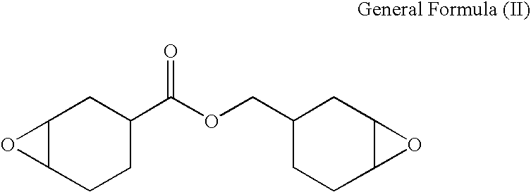
Applications Claiming Priority (2)
| Application Number | Priority Date | Filing Date | Title |
|---|---|---|---|
| JP2007161431A JP5173273B2 (en) | 2007-06-19 | 2007-06-19 | Sealant for inkjet head, inkjet head, and inkjet recording apparatus |
| JP2007-161431 | 2007-06-19 |
Publications (2)
| Publication Number | Publication Date |
|---|---|
| US20080317942A1 true US20080317942A1 (en) | 2008-12-25 |
| US8011778B2 US8011778B2 (en) | 2011-09-06 |
Family
ID=40136784
Family Applications (1)
| Application Number | Title | Priority Date | Filing Date |
|---|---|---|---|
| US12/135,977 Expired - Fee Related US8011778B2 (en) | 2007-06-19 | 2008-06-09 | Sealant for ink jet head, ink jet head, and ink jet recording apparatus |
Country Status (3)
| Country | Link |
|---|---|
| US (1) | US8011778B2 (en) |
| JP (1) | JP5173273B2 (en) |
| CN (1) | CN101328398A (en) |
Cited By (1)
| Publication number | Priority date | Publication date | Assignee | Title |
|---|---|---|---|---|
| US20130208053A1 (en) * | 2012-02-13 | 2013-08-15 | Canon Kabushiki Kaisha | Liquid discharging recording head |
Families Citing this family (9)
| Publication number | Priority date | Publication date | Assignee | Title |
|---|---|---|---|---|
| TW201031737A (en) * | 2009-02-03 | 2010-09-01 | Henkel Corp | Encapsulant for inkjet print head |
| JP5631054B2 (en) * | 2010-05-12 | 2014-11-26 | キヤノン株式会社 | Liquid discharge head and manufacturing method thereof |
| JP5780917B2 (en) * | 2011-10-25 | 2015-09-16 | キヤノン株式会社 | Wiring protective sealant for ink jet recording head, ink jet recording head using the same, and manufacturing method thereof |
| JP5858813B2 (en) | 2012-02-06 | 2016-02-10 | キヤノン株式会社 | Liquid discharge head and manufacturing method thereof |
| JP6066747B2 (en) * | 2012-03-02 | 2017-01-25 | キヤノン株式会社 | Method for manufacturing liquid discharge head and liquid discharge head manufactured by this manufacturing method |
| CN105377747B (en) * | 2013-07-24 | 2017-12-08 | Jsr株式会社 | Microfluidic device and its manufacture method, stream formation photosensitive polymer combination |
| WO2016052212A1 (en) * | 2014-10-02 | 2016-04-07 | 株式会社ダイセル | Curable composition for nanoimprinting |
| WO2018106089A1 (en) * | 2016-12-09 | 2018-06-14 | 주식회사 엘지화학 | Sealant composition |
| WO2021010226A1 (en) * | 2019-07-17 | 2021-01-21 | 積水化学工業株式会社 | Sealant for organic el display element |
Citations (17)
| Publication number | Priority date | Publication date | Assignee | Title |
|---|---|---|---|---|
| US5524784A (en) * | 1992-06-24 | 1996-06-11 | Canon Kabushiki Kaisha | Method for producing ink jet head by multiple development of photosensitive resin, ink jet head produced thereby, and ink jet apparatus with the ink jet head |
| US5663752A (en) * | 1993-11-26 | 1997-09-02 | Canon Kabushiki Kaisha | Ink jet head free of debonding between a substrate and ink flow path walls formed on said substrate |
| US5738911A (en) * | 1996-03-12 | 1998-04-14 | Canon Kabushiki Kaisha | Process for producing liquid-jet recording head, liquid-jet recording head produced thereby, and liquid-jet recording apparatus comprising the head |
| US5770271A (en) * | 1995-09-04 | 1998-06-23 | Canon Kabushiki Kaisha | Method for treating the surface of a base and production of an ink-jet recording head using the method |
| US5980026A (en) * | 1995-06-14 | 1999-11-09 | Canon Kabushiki Kaisha | Process for production of ink jet head |
| US6123410A (en) * | 1997-10-28 | 2000-09-26 | Hewlett-Packard Company | Scalable wide-array inkjet printhead and method for fabricating same |
| US6291545B2 (en) * | 1995-06-13 | 2001-09-18 | Canon Kabushiki Kaisha | Fluorine-containing epoxy resin composition readily soluble in solvent |
| US6409931B1 (en) * | 1998-01-26 | 2002-06-25 | Canon Kabushiki Kaisha | Method of producing ink jet recording head and ink jet recording head |
| US20030094738A1 (en) * | 2001-09-28 | 2003-05-22 | Brother Kogyo Kabushiki Kaisha | Active energy beam-curable composition, ink containing the same, and printer accommodating the same ink |
| US20030112307A1 (en) * | 2001-09-06 | 2003-06-19 | Brother Kogyo Kabushiki Kaisha | Active energy beam-curable composition, ink containing the same, and printer accommodating the same ink |
| US6586495B1 (en) * | 1999-09-20 | 2003-07-01 | Canon Kabushiki Kaisha | Alkylsiloxane-containing epoxy resin composition, surface modifying method using the same, ink-jet recording head and liquid-jet recording apparatus |
| US6750290B2 (en) * | 2001-04-19 | 2004-06-15 | Canon Kabushiki Kaisha | Epoxy resin composition, method of improving surface of substrate, ink jet recording head and ink jet recording apparatus |
| US20040155931A1 (en) * | 2003-02-06 | 2004-08-12 | Toshihiro Mori | Liquid jet recording head |
| US6846520B2 (en) * | 2002-01-17 | 2005-01-25 | Canon Kabushiki Kaisha | Epoxy resin composition, surface treatment method, liquid-jet recording head and liquid-jet recording apparatus |
| US6869541B2 (en) * | 2002-02-21 | 2005-03-22 | Canon Kabushiki Kaisha | Epoxy resin composition, surface treating method, ink-jet recording head, and ink-jet recording apparatus |
| US20060162771A1 (en) * | 2003-02-20 | 2006-07-27 | Nippon Kayaku Kabushiki Kaisha | Sealing agent for photoelectric conversion element and photoelectric conversion device element using the same |
| US20070142491A1 (en) * | 2005-12-16 | 2007-06-21 | Canon Kabushiki Kaisha | Resin composition, resin cured product, and liquid discharge head |
Family Cites Families (4)
| Publication number | Priority date | Publication date | Assignee | Title |
|---|---|---|---|---|
| JP4575601B2 (en) | 2001-01-09 | 2010-11-04 | ナミックス株式会社 | Method for manufacturing hollow structure electronic device |
| JP2002302536A (en) | 2001-04-03 | 2002-10-18 | Ricoh Co Ltd | Epoxy resin composition for producing inkjet head and method for producing inkjet head |
| JP4402468B2 (en) * | 2003-02-06 | 2010-01-20 | キヤノン株式会社 | Liquid jet recording head |
| JP4713269B2 (en) * | 2005-08-08 | 2011-06-29 | ソニー株式会社 | Manufacturing method of liquid discharge type recording head |
-
2007
- 2007-06-19 JP JP2007161431A patent/JP5173273B2/en active Active
-
2008
- 2008-06-09 US US12/135,977 patent/US8011778B2/en not_active Expired - Fee Related
- 2008-06-19 CN CNA2008101114606A patent/CN101328398A/en active Pending
Patent Citations (18)
| Publication number | Priority date | Publication date | Assignee | Title |
|---|---|---|---|---|
| US5524784A (en) * | 1992-06-24 | 1996-06-11 | Canon Kabushiki Kaisha | Method for producing ink jet head by multiple development of photosensitive resin, ink jet head produced thereby, and ink jet apparatus with the ink jet head |
| US5663752A (en) * | 1993-11-26 | 1997-09-02 | Canon Kabushiki Kaisha | Ink jet head free of debonding between a substrate and ink flow path walls formed on said substrate |
| US6291545B2 (en) * | 1995-06-13 | 2001-09-18 | Canon Kabushiki Kaisha | Fluorine-containing epoxy resin composition readily soluble in solvent |
| US5980026A (en) * | 1995-06-14 | 1999-11-09 | Canon Kabushiki Kaisha | Process for production of ink jet head |
| US5770271A (en) * | 1995-09-04 | 1998-06-23 | Canon Kabushiki Kaisha | Method for treating the surface of a base and production of an ink-jet recording head using the method |
| US5738911A (en) * | 1996-03-12 | 1998-04-14 | Canon Kabushiki Kaisha | Process for producing liquid-jet recording head, liquid-jet recording head produced thereby, and liquid-jet recording apparatus comprising the head |
| US6123410A (en) * | 1997-10-28 | 2000-09-26 | Hewlett-Packard Company | Scalable wide-array inkjet printhead and method for fabricating same |
| US6409931B1 (en) * | 1998-01-26 | 2002-06-25 | Canon Kabushiki Kaisha | Method of producing ink jet recording head and ink jet recording head |
| US6586495B1 (en) * | 1999-09-20 | 2003-07-01 | Canon Kabushiki Kaisha | Alkylsiloxane-containing epoxy resin composition, surface modifying method using the same, ink-jet recording head and liquid-jet recording apparatus |
| US6713128B2 (en) * | 1999-09-20 | 2004-03-30 | Canon Kabushiki Kaisha | Alkylsiloxane-containing epoxy resin composition, surface modifying method using the same, ink-jet recording head and liquid-jet recording apparatus |
| US6750290B2 (en) * | 2001-04-19 | 2004-06-15 | Canon Kabushiki Kaisha | Epoxy resin composition, method of improving surface of substrate, ink jet recording head and ink jet recording apparatus |
| US20030112307A1 (en) * | 2001-09-06 | 2003-06-19 | Brother Kogyo Kabushiki Kaisha | Active energy beam-curable composition, ink containing the same, and printer accommodating the same ink |
| US20030094738A1 (en) * | 2001-09-28 | 2003-05-22 | Brother Kogyo Kabushiki Kaisha | Active energy beam-curable composition, ink containing the same, and printer accommodating the same ink |
| US6846520B2 (en) * | 2002-01-17 | 2005-01-25 | Canon Kabushiki Kaisha | Epoxy resin composition, surface treatment method, liquid-jet recording head and liquid-jet recording apparatus |
| US6869541B2 (en) * | 2002-02-21 | 2005-03-22 | Canon Kabushiki Kaisha | Epoxy resin composition, surface treating method, ink-jet recording head, and ink-jet recording apparatus |
| US20040155931A1 (en) * | 2003-02-06 | 2004-08-12 | Toshihiro Mori | Liquid jet recording head |
| US20060162771A1 (en) * | 2003-02-20 | 2006-07-27 | Nippon Kayaku Kabushiki Kaisha | Sealing agent for photoelectric conversion element and photoelectric conversion device element using the same |
| US20070142491A1 (en) * | 2005-12-16 | 2007-06-21 | Canon Kabushiki Kaisha | Resin composition, resin cured product, and liquid discharge head |
Cited By (2)
| Publication number | Priority date | Publication date | Assignee | Title |
|---|---|---|---|---|
| US20130208053A1 (en) * | 2012-02-13 | 2013-08-15 | Canon Kabushiki Kaisha | Liquid discharging recording head |
| US8926067B2 (en) * | 2012-02-13 | 2015-01-06 | Canon Kabushiki Kaisha | Liquid discharging recording head |
Also Published As
| Publication number | Publication date |
|---|---|
| US8011778B2 (en) | 2011-09-06 |
| JP5173273B2 (en) | 2013-04-03 |
| JP2009000830A (en) | 2009-01-08 |
| CN101328398A (en) | 2008-12-24 |
Similar Documents
| Publication | Publication Date | Title |
|---|---|---|
| US8011778B2 (en) | Sealant for ink jet head, ink jet head, and ink jet recording apparatus | |
| EP2586808B1 (en) | Sealant, inkjet recording head using sealant, and method for manufacturing the same | |
| RU2664650C2 (en) | Liquid jet head and method of its production, liquid jet device and image formation device | |
| EP2028242B1 (en) | Inkjet ink, and ink cartridge, inkjet recording method, inkjet recording apparatus and ink record using the same | |
| US7922860B2 (en) | Manufacturing inkjet head by adhering with epoxy resins and alkyl imidazole | |
| US20070236542A1 (en) | Adhesive Compositions, Micro-Fluid Ejection Devices, and Methods for Attaching Micro-Fluid Ejection Heads | |
| US7709554B2 (en) | Resin composition, resin cured product, and liquid discharge head | |
| WO2007100121A1 (en) | Inkjet recording apparatus and inkjet recording method | |
| US8439483B2 (en) | Liquid ejection head and method of producing the same | |
| US7766455B2 (en) | Flexible adhesive materials for micro-fluid ejection heads and methods relating thereto | |
| US20100315462A1 (en) | Liquid discharge head and method for manufacturing the same | |
| US20150035903A1 (en) | Inkjet Printheads Containing Epoxy Adhesives and Methods for Fabrication Thereof | |
| JPH1076653A (en) | Improved thermal ink jet print head and preparing method thereof | |
| JP5849552B2 (en) | Ink jet head, manufacturing method thereof, and image forming apparatus | |
| JP2007331334A (en) | Inkjet recording head, its manufacturing method and wiring protection sealant for inkjet recording head | |
| US20140255610A1 (en) | Thermally stable oleophobic anti-wetting coating for inkjet printhead face | |
| JP4996097B2 (en) | Method for manufacturing ink jet recording head | |
| JP2013059966A (en) | Liquid ejection head | |
| JP5754378B2 (en) | Inkjet head manufacturing method | |
| US11305538B2 (en) | Method of manufacturing microstructure and method of manufacturing liquid ejection head | |
| JP7276490B2 (en) | Inkjet head and method for manufacturing inkjet head | |
| US10589528B2 (en) | Liquid discharge head, method for producing the same, liquid discharge apparatus, and image forming apparatus | |
| US20090141085A1 (en) | Liquid discharge head and its manufacturing method | |
| US10507645B2 (en) | Inkjet printing apparatus and inkjet printing method | |
| JP4474008B2 (en) | Ink, method for improving intermittent ejection property of ink jet recording apparatus, image recording method, and ink set |
Legal Events
| Date | Code | Title | Description |
|---|---|---|---|
| AS | Assignment |
Owner name: CANON KABUSHIKI KAISHA, JAPAN Free format text: ASSIGNMENT OF ASSIGNORS INTEREST;ASSIGNORS:HARADA, KOUJI;IMAMURA, ISAO;REEL/FRAME:021166/0767 Effective date: 20080606 |
|
| STCF | Information on status: patent grant |
Free format text: PATENTED CASE |
|
| FPAY | Fee payment |
Year of fee payment: 4 |
|
| FEPP | Fee payment procedure |
Free format text: MAINTENANCE FEE REMINDER MAILED (ORIGINAL EVENT CODE: REM.); ENTITY STATUS OF PATENT OWNER: LARGE ENTITY |
|
| LAPS | Lapse for failure to pay maintenance fees |
Free format text: PATENT EXPIRED FOR FAILURE TO PAY MAINTENANCE FEES (ORIGINAL EVENT CODE: EXP.); ENTITY STATUS OF PATENT OWNER: LARGE ENTITY |
|
| STCH | Information on status: patent discontinuation |
Free format text: PATENT EXPIRED DUE TO NONPAYMENT OF MAINTENANCE FEES UNDER 37 CFR 1.362 |
|
| FP | Lapsed due to failure to pay maintenance fee |
Effective date: 20190906 |