US20090306673A1 - Kit and method for fixating a prosthesis or part thereof and/or filling osseous defects - Google Patents
Kit and method for fixating a prosthesis or part thereof and/or filling osseous defects Download PDFInfo
- Publication number
- US20090306673A1 US20090306673A1 US12/463,038 US46303809A US2009306673A1 US 20090306673 A1 US20090306673 A1 US 20090306673A1 US 46303809 A US46303809 A US 46303809A US 2009306673 A1 US2009306673 A1 US 2009306673A1
- Authority
- US
- United States
- Prior art keywords
- granules
- bone
- kit
- layer
- prosthesis
- Prior art date
- Legal status (The legal status is an assumption and is not a legal conclusion. Google has not performed a legal analysis and makes no representation as to the accuracy of the status listed.)
- Granted
Links
- HZKPBSGNXJZVBD-UHFFFAOYSA-N C.C.C.C.C.C.C.C.C.C.C.C.C.C.C.C.C.C.C.C.C.C.P.P.P.[Ce].[Ti] Chemical compound C.C.C.C.C.C.C.C.C.C.C.C.C.C.C.C.C.C.C.C.C.C.P.P.P.[Ce].[Ti] HZKPBSGNXJZVBD-UHFFFAOYSA-N 0.000 description 1
Images


Classifications
-
- A—HUMAN NECESSITIES
- A61—MEDICAL OR VETERINARY SCIENCE; HYGIENE
- A61F—FILTERS IMPLANTABLE INTO BLOOD VESSELS; PROSTHESES; DEVICES PROVIDING PATENCY TO, OR PREVENTING COLLAPSING OF, TUBULAR STRUCTURES OF THE BODY, e.g. STENTS; ORTHOPAEDIC, NURSING OR CONTRACEPTIVE DEVICES; FOMENTATION; TREATMENT OR PROTECTION OF EYES OR EARS; BANDAGES, DRESSINGS OR ABSORBENT PADS; FIRST-AID KITS
- A61F2/00—Filters implantable into blood vessels; Prostheses, i.e. artificial substitutes or replacements for parts of the body; Appliances for connecting them with the body; Devices providing patency to, or preventing collapsing of, tubular structures of the body, e.g. stents
- A61F2/02—Prostheses implantable into the body
- A61F2/30—Joints
- A61F2/46—Special tools or methods for implanting or extracting artificial joints, accessories, bone grafts or substitutes, or particular adaptations therefor
- A61F2/468—Testing instruments for artificial joints
-
- A—HUMAN NECESSITIES
- A61—MEDICAL OR VETERINARY SCIENCE; HYGIENE
- A61F—FILTERS IMPLANTABLE INTO BLOOD VESSELS; PROSTHESES; DEVICES PROVIDING PATENCY TO, OR PREVENTING COLLAPSING OF, TUBULAR STRUCTURES OF THE BODY, e.g. STENTS; ORTHOPAEDIC, NURSING OR CONTRACEPTIVE DEVICES; FOMENTATION; TREATMENT OR PROTECTION OF EYES OR EARS; BANDAGES, DRESSINGS OR ABSORBENT PADS; FIRST-AID KITS
- A61F2/00—Filters implantable into blood vessels; Prostheses, i.e. artificial substitutes or replacements for parts of the body; Appliances for connecting them with the body; Devices providing patency to, or preventing collapsing of, tubular structures of the body, e.g. stents
- A61F2/02—Prostheses implantable into the body
- A61F2/30—Joints
- A61F2/46—Special tools or methods for implanting or extracting artificial joints, accessories, bone grafts or substitutes, or particular adaptations therefor
- A61F2/4601—Special tools or methods for implanting or extracting artificial joints, accessories, bone grafts or substitutes, or particular adaptations therefor for introducing bone substitute, for implanting bone graft implants or for compacting them in the bone cavity
-
- A—HUMAN NECESSITIES
- A61—MEDICAL OR VETERINARY SCIENCE; HYGIENE
- A61L—METHODS OR APPARATUS FOR STERILISING MATERIALS OR OBJECTS IN GENERAL; DISINFECTION, STERILISATION OR DEODORISATION OF AIR; CHEMICAL ASPECTS OF BANDAGES, DRESSINGS, ABSORBENT PADS OR SURGICAL ARTICLES; MATERIALS FOR BANDAGES, DRESSINGS, ABSORBENT PADS OR SURGICAL ARTICLES
- A61L27/00—Materials for grafts or prostheses or for coating grafts or prostheses
- A61L27/02—Inorganic materials
- A61L27/04—Metals or alloys
-
- A—HUMAN NECESSITIES
- A61—MEDICAL OR VETERINARY SCIENCE; HYGIENE
- A61L—METHODS OR APPARATUS FOR STERILISING MATERIALS OR OBJECTS IN GENERAL; DISINFECTION, STERILISATION OR DEODORISATION OF AIR; CHEMICAL ASPECTS OF BANDAGES, DRESSINGS, ABSORBENT PADS OR SURGICAL ARTICLES; MATERIALS FOR BANDAGES, DRESSINGS, ABSORBENT PADS OR SURGICAL ARTICLES
- A61L27/00—Materials for grafts or prostheses or for coating grafts or prostheses
- A61L27/14—Macromolecular materials
- A61L27/16—Macromolecular materials obtained by reactions only involving carbon-to-carbon unsaturated bonds
-
- A—HUMAN NECESSITIES
- A61—MEDICAL OR VETERINARY SCIENCE; HYGIENE
- A61L—METHODS OR APPARATUS FOR STERILISING MATERIALS OR OBJECTS IN GENERAL; DISINFECTION, STERILISATION OR DEODORISATION OF AIR; CHEMICAL ASPECTS OF BANDAGES, DRESSINGS, ABSORBENT PADS OR SURGICAL ARTICLES; MATERIALS FOR BANDAGES, DRESSINGS, ABSORBENT PADS OR SURGICAL ARTICLES
- A61L27/00—Materials for grafts or prostheses or for coating grafts or prostheses
- A61L27/50—Materials characterised by their function or physical properties, e.g. injectable or lubricating compositions, shape-memory materials, surface modified materials
- A61L27/56—Porous materials, e.g. foams or sponges
-
- C—CHEMISTRY; METALLURGY
- C23—COATING METALLIC MATERIAL; COATING MATERIAL WITH METALLIC MATERIAL; CHEMICAL SURFACE TREATMENT; DIFFUSION TREATMENT OF METALLIC MATERIAL; COATING BY VACUUM EVAPORATION, BY SPUTTERING, BY ION IMPLANTATION OR BY CHEMICAL VAPOUR DEPOSITION, IN GENERAL; INHIBITING CORROSION OF METALLIC MATERIAL OR INCRUSTATION IN GENERAL
- C23C—COATING METALLIC MATERIAL; COATING MATERIAL WITH METALLIC MATERIAL; SURFACE TREATMENT OF METALLIC MATERIAL BY DIFFUSION INTO THE SURFACE, BY CHEMICAL CONVERSION OR SUBSTITUTION; COATING BY VACUUM EVAPORATION, BY SPUTTERING, BY ION IMPLANTATION OR BY CHEMICAL VAPOUR DEPOSITION, IN GENERAL
- C23C30/00—Coating with metallic material characterised only by the composition of the metallic material, i.e. not characterised by the coating process
-
- A—HUMAN NECESSITIES
- A61—MEDICAL OR VETERINARY SCIENCE; HYGIENE
- A61B—DIAGNOSIS; SURGERY; IDENTIFICATION
- A61B17/00—Surgical instruments, devices or methods, e.g. tourniquets
- A61B17/56—Surgical instruments or methods for treatment of bones or joints; Devices specially adapted therefor
- A61B17/58—Surgical instruments or methods for treatment of bones or joints; Devices specially adapted therefor for osteosynthesis, e.g. bone plates, screws, setting implements or the like
- A61B17/68—Internal fixation devices, including fasteners and spinal fixators, even if a part thereof projects from the skin
- A61B17/70—Spinal positioners or stabilisers ; Bone stabilisers comprising fluid filler in an implant
- A61B17/7094—Solid vertebral fillers; devices for inserting such fillers
- A61B17/7095—Solid vertebral fillers; devices for inserting such fillers the filler comprising unlinked macroscopic particles
-
- A—HUMAN NECESSITIES
- A61—MEDICAL OR VETERINARY SCIENCE; HYGIENE
- A61B—DIAGNOSIS; SURGERY; IDENTIFICATION
- A61B17/00—Surgical instruments, devices or methods, e.g. tourniquets
- A61B17/56—Surgical instruments or methods for treatment of bones or joints; Devices specially adapted therefor
- A61B17/58—Surgical instruments or methods for treatment of bones or joints; Devices specially adapted therefor for osteosynthesis, e.g. bone plates, screws, setting implements or the like
- A61B17/88—Osteosynthesis instruments; Methods or means for implanting or extracting internal or external fixation devices
- A61B17/8802—Equipment for handling bone cement or other fluid fillers
- A61B17/8847—Equipment for handling bone cement or other fluid fillers for removing cement from a bone cavity
-
- A—HUMAN NECESSITIES
- A61—MEDICAL OR VETERINARY SCIENCE; HYGIENE
- A61B—DIAGNOSIS; SURGERY; IDENTIFICATION
- A61B17/00—Surgical instruments, devices or methods, e.g. tourniquets
- A61B17/56—Surgical instruments or methods for treatment of bones or joints; Devices specially adapted therefor
- A61B17/58—Surgical instruments or methods for treatment of bones or joints; Devices specially adapted therefor for osteosynthesis, e.g. bone plates, screws, setting implements or the like
- A61B17/88—Osteosynthesis instruments; Methods or means for implanting or extracting internal or external fixation devices
- A61B17/885—Tools for expanding or compacting bones or discs or cavities therein
-
- A—HUMAN NECESSITIES
- A61—MEDICAL OR VETERINARY SCIENCE; HYGIENE
- A61F—FILTERS IMPLANTABLE INTO BLOOD VESSELS; PROSTHESES; DEVICES PROVIDING PATENCY TO, OR PREVENTING COLLAPSING OF, TUBULAR STRUCTURES OF THE BODY, e.g. STENTS; ORTHOPAEDIC, NURSING OR CONTRACEPTIVE DEVICES; FOMENTATION; TREATMENT OR PROTECTION OF EYES OR EARS; BANDAGES, DRESSINGS OR ABSORBENT PADS; FIRST-AID KITS
- A61F2/00—Filters implantable into blood vessels; Prostheses, i.e. artificial substitutes or replacements for parts of the body; Appliances for connecting them with the body; Devices providing patency to, or preventing collapsing of, tubular structures of the body, e.g. stents
- A61F2/0077—Special surfaces of prostheses, e.g. for improving ingrowth
-
- A—HUMAN NECESSITIES
- A61—MEDICAL OR VETERINARY SCIENCE; HYGIENE
- A61F—FILTERS IMPLANTABLE INTO BLOOD VESSELS; PROSTHESES; DEVICES PROVIDING PATENCY TO, OR PREVENTING COLLAPSING OF, TUBULAR STRUCTURES OF THE BODY, e.g. STENTS; ORTHOPAEDIC, NURSING OR CONTRACEPTIVE DEVICES; FOMENTATION; TREATMENT OR PROTECTION OF EYES OR EARS; BANDAGES, DRESSINGS OR ABSORBENT PADS; FIRST-AID KITS
- A61F2/00—Filters implantable into blood vessels; Prostheses, i.e. artificial substitutes or replacements for parts of the body; Appliances for connecting them with the body; Devices providing patency to, or preventing collapsing of, tubular structures of the body, e.g. stents
- A61F2/02—Prostheses implantable into the body
- A61F2/30—Joints
- A61F2/30721—Accessories
- A61F2/30723—Plugs or restrictors for sealing a cement-receiving space
-
- A—HUMAN NECESSITIES
- A61—MEDICAL OR VETERINARY SCIENCE; HYGIENE
- A61F—FILTERS IMPLANTABLE INTO BLOOD VESSELS; PROSTHESES; DEVICES PROVIDING PATENCY TO, OR PREVENTING COLLAPSING OF, TUBULAR STRUCTURES OF THE BODY, e.g. STENTS; ORTHOPAEDIC, NURSING OR CONTRACEPTIVE DEVICES; FOMENTATION; TREATMENT OR PROTECTION OF EYES OR EARS; BANDAGES, DRESSINGS OR ABSORBENT PADS; FIRST-AID KITS
- A61F2/00—Filters implantable into blood vessels; Prostheses, i.e. artificial substitutes or replacements for parts of the body; Appliances for connecting them with the body; Devices providing patency to, or preventing collapsing of, tubular structures of the body, e.g. stents
- A61F2/02—Prostheses implantable into the body
- A61F2/30—Joints
- A61F2/30721—Accessories
- A61F2/30749—Fixation appliances for connecting prostheses to the body
-
- A—HUMAN NECESSITIES
- A61—MEDICAL OR VETERINARY SCIENCE; HYGIENE
- A61F—FILTERS IMPLANTABLE INTO BLOOD VESSELS; PROSTHESES; DEVICES PROVIDING PATENCY TO, OR PREVENTING COLLAPSING OF, TUBULAR STRUCTURES OF THE BODY, e.g. STENTS; ORTHOPAEDIC, NURSING OR CONTRACEPTIVE DEVICES; FOMENTATION; TREATMENT OR PROTECTION OF EYES OR EARS; BANDAGES, DRESSINGS OR ABSORBENT PADS; FIRST-AID KITS
- A61F2/00—Filters implantable into blood vessels; Prostheses, i.e. artificial substitutes or replacements for parts of the body; Appliances for connecting them with the body; Devices providing patency to, or preventing collapsing of, tubular structures of the body, e.g. stents
- A61F2/02—Prostheses implantable into the body
- A61F2/30—Joints
- A61F2/30767—Special external or bone-contacting surface, e.g. coating for improving bone ingrowth
-
- A—HUMAN NECESSITIES
- A61—MEDICAL OR VETERINARY SCIENCE; HYGIENE
- A61F—FILTERS IMPLANTABLE INTO BLOOD VESSELS; PROSTHESES; DEVICES PROVIDING PATENCY TO, OR PREVENTING COLLAPSING OF, TUBULAR STRUCTURES OF THE BODY, e.g. STENTS; ORTHOPAEDIC, NURSING OR CONTRACEPTIVE DEVICES; FOMENTATION; TREATMENT OR PROTECTION OF EYES OR EARS; BANDAGES, DRESSINGS OR ABSORBENT PADS; FIRST-AID KITS
- A61F2/00—Filters implantable into blood vessels; Prostheses, i.e. artificial substitutes or replacements for parts of the body; Appliances for connecting them with the body; Devices providing patency to, or preventing collapsing of, tubular structures of the body, e.g. stents
- A61F2/02—Prostheses implantable into the body
- A61F2/30—Joints
- A61F2/3094—Designing or manufacturing processes
-
- A—HUMAN NECESSITIES
- A61—MEDICAL OR VETERINARY SCIENCE; HYGIENE
- A61F—FILTERS IMPLANTABLE INTO BLOOD VESSELS; PROSTHESES; DEVICES PROVIDING PATENCY TO, OR PREVENTING COLLAPSING OF, TUBULAR STRUCTURES OF THE BODY, e.g. STENTS; ORTHOPAEDIC, NURSING OR CONTRACEPTIVE DEVICES; FOMENTATION; TREATMENT OR PROTECTION OF EYES OR EARS; BANDAGES, DRESSINGS OR ABSORBENT PADS; FIRST-AID KITS
- A61F2/00—Filters implantable into blood vessels; Prostheses, i.e. artificial substitutes or replacements for parts of the body; Appliances for connecting them with the body; Devices providing patency to, or preventing collapsing of, tubular structures of the body, e.g. stents
- A61F2/02—Prostheses implantable into the body
- A61F2/30—Joints
- A61F2/32—Joints for the hip
- A61F2/34—Acetabular cups
-
- A—HUMAN NECESSITIES
- A61—MEDICAL OR VETERINARY SCIENCE; HYGIENE
- A61F—FILTERS IMPLANTABLE INTO BLOOD VESSELS; PROSTHESES; DEVICES PROVIDING PATENCY TO, OR PREVENTING COLLAPSING OF, TUBULAR STRUCTURES OF THE BODY, e.g. STENTS; ORTHOPAEDIC, NURSING OR CONTRACEPTIVE DEVICES; FOMENTATION; TREATMENT OR PROTECTION OF EYES OR EARS; BANDAGES, DRESSINGS OR ABSORBENT PADS; FIRST-AID KITS
- A61F2/00—Filters implantable into blood vessels; Prostheses, i.e. artificial substitutes or replacements for parts of the body; Appliances for connecting them with the body; Devices providing patency to, or preventing collapsing of, tubular structures of the body, e.g. stents
- A61F2/02—Prostheses implantable into the body
- A61F2/30—Joints
- A61F2/32—Joints for the hip
- A61F2/36—Femoral heads ; Femoral endoprostheses
- A61F2/3662—Femoral shafts
- A61F2/3676—Distal or diaphyseal parts of shafts
-
- A—HUMAN NECESSITIES
- A61—MEDICAL OR VETERINARY SCIENCE; HYGIENE
- A61F—FILTERS IMPLANTABLE INTO BLOOD VESSELS; PROSTHESES; DEVICES PROVIDING PATENCY TO, OR PREVENTING COLLAPSING OF, TUBULAR STRUCTURES OF THE BODY, e.g. STENTS; ORTHOPAEDIC, NURSING OR CONTRACEPTIVE DEVICES; FOMENTATION; TREATMENT OR PROTECTION OF EYES OR EARS; BANDAGES, DRESSINGS OR ABSORBENT PADS; FIRST-AID KITS
- A61F2/00—Filters implantable into blood vessels; Prostheses, i.e. artificial substitutes or replacements for parts of the body; Appliances for connecting them with the body; Devices providing patency to, or preventing collapsing of, tubular structures of the body, e.g. stents
- A61F2/02—Prostheses implantable into the body
- A61F2/28—Bones
- A61F2002/2835—Bone graft implants for filling a bony defect or an endoprosthesis cavity, e.g. by synthetic material or biological material
-
- A—HUMAN NECESSITIES
- A61—MEDICAL OR VETERINARY SCIENCE; HYGIENE
- A61F—FILTERS IMPLANTABLE INTO BLOOD VESSELS; PROSTHESES; DEVICES PROVIDING PATENCY TO, OR PREVENTING COLLAPSING OF, TUBULAR STRUCTURES OF THE BODY, e.g. STENTS; ORTHOPAEDIC, NURSING OR CONTRACEPTIVE DEVICES; FOMENTATION; TREATMENT OR PROTECTION OF EYES OR EARS; BANDAGES, DRESSINGS OR ABSORBENT PADS; FIRST-AID KITS
- A61F2/00—Filters implantable into blood vessels; Prostheses, i.e. artificial substitutes or replacements for parts of the body; Appliances for connecting them with the body; Devices providing patency to, or preventing collapsing of, tubular structures of the body, e.g. stents
- A61F2/02—Prostheses implantable into the body
- A61F2/30—Joints
- A61F2002/30001—Additional features of subject-matter classified in A61F2/28, A61F2/30 and subgroups thereof
- A61F2002/30108—Shapes
- A61F2002/3011—Cross-sections or two-dimensional shapes
- A61F2002/30112—Rounded shapes, e.g. with rounded corners
- A61F2002/30125—Rounded shapes, e.g. with rounded corners elliptical or oval
-
- A—HUMAN NECESSITIES
- A61—MEDICAL OR VETERINARY SCIENCE; HYGIENE
- A61F—FILTERS IMPLANTABLE INTO BLOOD VESSELS; PROSTHESES; DEVICES PROVIDING PATENCY TO, OR PREVENTING COLLAPSING OF, TUBULAR STRUCTURES OF THE BODY, e.g. STENTS; ORTHOPAEDIC, NURSING OR CONTRACEPTIVE DEVICES; FOMENTATION; TREATMENT OR PROTECTION OF EYES OR EARS; BANDAGES, DRESSINGS OR ABSORBENT PADS; FIRST-AID KITS
- A61F2/00—Filters implantable into blood vessels; Prostheses, i.e. artificial substitutes or replacements for parts of the body; Appliances for connecting them with the body; Devices providing patency to, or preventing collapsing of, tubular structures of the body, e.g. stents
- A61F2/02—Prostheses implantable into the body
- A61F2/30—Joints
- A61F2002/30001—Additional features of subject-matter classified in A61F2/28, A61F2/30 and subgroups thereof
- A61F2002/30316—The prosthesis having different structural features at different locations within the same prosthesis; Connections between prosthetic parts; Special structural features of bone or joint prostheses not otherwise provided for
- A61F2002/30535—Special structural features of bone or joint prostheses not otherwise provided for
- A61F2002/30581—Special structural features of bone or joint prostheses not otherwise provided for having a pocket filled with fluid, e.g. liquid
- A61F2002/30588—Special structural features of bone or joint prostheses not otherwise provided for having a pocket filled with fluid, e.g. liquid filled with solid particles
-
- A—HUMAN NECESSITIES
- A61—MEDICAL OR VETERINARY SCIENCE; HYGIENE
- A61F—FILTERS IMPLANTABLE INTO BLOOD VESSELS; PROSTHESES; DEVICES PROVIDING PATENCY TO, OR PREVENTING COLLAPSING OF, TUBULAR STRUCTURES OF THE BODY, e.g. STENTS; ORTHOPAEDIC, NURSING OR CONTRACEPTIVE DEVICES; FOMENTATION; TREATMENT OR PROTECTION OF EYES OR EARS; BANDAGES, DRESSINGS OR ABSORBENT PADS; FIRST-AID KITS
- A61F2/00—Filters implantable into blood vessels; Prostheses, i.e. artificial substitutes or replacements for parts of the body; Appliances for connecting them with the body; Devices providing patency to, or preventing collapsing of, tubular structures of the body, e.g. stents
- A61F2/02—Prostheses implantable into the body
- A61F2/30—Joints
- A61F2002/30001—Additional features of subject-matter classified in A61F2/28, A61F2/30 and subgroups thereof
- A61F2002/30667—Features concerning an interaction with the environment or a particular use of the prosthesis
- A61F2002/3069—Revision endoprostheses
-
- A—HUMAN NECESSITIES
- A61—MEDICAL OR VETERINARY SCIENCE; HYGIENE
- A61F—FILTERS IMPLANTABLE INTO BLOOD VESSELS; PROSTHESES; DEVICES PROVIDING PATENCY TO, OR PREVENTING COLLAPSING OF, TUBULAR STRUCTURES OF THE BODY, e.g. STENTS; ORTHOPAEDIC, NURSING OR CONTRACEPTIVE DEVICES; FOMENTATION; TREATMENT OR PROTECTION OF EYES OR EARS; BANDAGES, DRESSINGS OR ABSORBENT PADS; FIRST-AID KITS
- A61F2/00—Filters implantable into blood vessels; Prostheses, i.e. artificial substitutes or replacements for parts of the body; Appliances for connecting them with the body; Devices providing patency to, or preventing collapsing of, tubular structures of the body, e.g. stents
- A61F2/02—Prostheses implantable into the body
- A61F2/30—Joints
- A61F2/30721—Accessories
- A61F2/30724—Spacers for centering an implant in a bone cavity, e.g. in a cement-receiving cavity
- A61F2002/30726—Centering or guiding rods, e.g. for insertion of femoral shafts
-
- A—HUMAN NECESSITIES
- A61—MEDICAL OR VETERINARY SCIENCE; HYGIENE
- A61F—FILTERS IMPLANTABLE INTO BLOOD VESSELS; PROSTHESES; DEVICES PROVIDING PATENCY TO, OR PREVENTING COLLAPSING OF, TUBULAR STRUCTURES OF THE BODY, e.g. STENTS; ORTHOPAEDIC, NURSING OR CONTRACEPTIVE DEVICES; FOMENTATION; TREATMENT OR PROTECTION OF EYES OR EARS; BANDAGES, DRESSINGS OR ABSORBENT PADS; FIRST-AID KITS
- A61F2/00—Filters implantable into blood vessels; Prostheses, i.e. artificial substitutes or replacements for parts of the body; Appliances for connecting them with the body; Devices providing patency to, or preventing collapsing of, tubular structures of the body, e.g. stents
- A61F2/02—Prostheses implantable into the body
- A61F2/30—Joints
- A61F2/30767—Special external or bone-contacting surface, e.g. coating for improving bone ingrowth
- A61F2002/3092—Special external or bone-contacting surface, e.g. coating for improving bone ingrowth having an open-celled or open-pored structure
-
- A—HUMAN NECESSITIES
- A61—MEDICAL OR VETERINARY SCIENCE; HYGIENE
- A61F—FILTERS IMPLANTABLE INTO BLOOD VESSELS; PROSTHESES; DEVICES PROVIDING PATENCY TO, OR PREVENTING COLLAPSING OF, TUBULAR STRUCTURES OF THE BODY, e.g. STENTS; ORTHOPAEDIC, NURSING OR CONTRACEPTIVE DEVICES; FOMENTATION; TREATMENT OR PROTECTION OF EYES OR EARS; BANDAGES, DRESSINGS OR ABSORBENT PADS; FIRST-AID KITS
- A61F2/00—Filters implantable into blood vessels; Prostheses, i.e. artificial substitutes or replacements for parts of the body; Appliances for connecting them with the body; Devices providing patency to, or preventing collapsing of, tubular structures of the body, e.g. stents
- A61F2/02—Prostheses implantable into the body
- A61F2/30—Joints
- A61F2/46—Special tools or methods for implanting or extracting artificial joints, accessories, bone grafts or substitutes, or particular adaptations therefor
- A61F2002/4631—Special tools or methods for implanting or extracting artificial joints, accessories, bone grafts or substitutes, or particular adaptations therefor the prosthesis being specially adapted for being cemented
-
- A—HUMAN NECESSITIES
- A61—MEDICAL OR VETERINARY SCIENCE; HYGIENE
- A61F—FILTERS IMPLANTABLE INTO BLOOD VESSELS; PROSTHESES; DEVICES PROVIDING PATENCY TO, OR PREVENTING COLLAPSING OF, TUBULAR STRUCTURES OF THE BODY, e.g. STENTS; ORTHOPAEDIC, NURSING OR CONTRACEPTIVE DEVICES; FOMENTATION; TREATMENT OR PROTECTION OF EYES OR EARS; BANDAGES, DRESSINGS OR ABSORBENT PADS; FIRST-AID KITS
- A61F2/00—Filters implantable into blood vessels; Prostheses, i.e. artificial substitutes or replacements for parts of the body; Appliances for connecting them with the body; Devices providing patency to, or preventing collapsing of, tubular structures of the body, e.g. stents
- A61F2/02—Prostheses implantable into the body
- A61F2/30—Joints
- A61F2/46—Special tools or methods for implanting or extracting artificial joints, accessories, bone grafts or substitutes, or particular adaptations therefor
- A61F2002/4677—Special tools or methods for implanting or extracting artificial joints, accessories, bone grafts or substitutes, or particular adaptations therefor using a guide wire
-
- A—HUMAN NECESSITIES
- A61—MEDICAL OR VETERINARY SCIENCE; HYGIENE
- A61F—FILTERS IMPLANTABLE INTO BLOOD VESSELS; PROSTHESES; DEVICES PROVIDING PATENCY TO, OR PREVENTING COLLAPSING OF, TUBULAR STRUCTURES OF THE BODY, e.g. STENTS; ORTHOPAEDIC, NURSING OR CONTRACEPTIVE DEVICES; FOMENTATION; TREATMENT OR PROTECTION OF EYES OR EARS; BANDAGES, DRESSINGS OR ABSORBENT PADS; FIRST-AID KITS
- A61F2/00—Filters implantable into blood vessels; Prostheses, i.e. artificial substitutes or replacements for parts of the body; Appliances for connecting them with the body; Devices providing patency to, or preventing collapsing of, tubular structures of the body, e.g. stents
- A61F2/02—Prostheses implantable into the body
- A61F2/30—Joints
- A61F2/46—Special tools or methods for implanting or extracting artificial joints, accessories, bone grafts or substitutes, or particular adaptations therefor
- A61F2002/4681—Special tools or methods for implanting or extracting artificial joints, accessories, bone grafts or substitutes, or particular adaptations therefor by applying mechanical shocks, e.g. by hammering
-
- A—HUMAN NECESSITIES
- A61—MEDICAL OR VETERINARY SCIENCE; HYGIENE
- A61F—FILTERS IMPLANTABLE INTO BLOOD VESSELS; PROSTHESES; DEVICES PROVIDING PATENCY TO, OR PREVENTING COLLAPSING OF, TUBULAR STRUCTURES OF THE BODY, e.g. STENTS; ORTHOPAEDIC, NURSING OR CONTRACEPTIVE DEVICES; FOMENTATION; TREATMENT OR PROTECTION OF EYES OR EARS; BANDAGES, DRESSINGS OR ABSORBENT PADS; FIRST-AID KITS
- A61F2220/00—Fixations or connections for prostheses classified in groups A61F2/00 - A61F2/26 or A61F2/82 or A61F9/00 or A61F11/00 or subgroups thereof
- A61F2220/0008—Fixation appliances for connecting prostheses to the body
-
- A—HUMAN NECESSITIES
- A61—MEDICAL OR VETERINARY SCIENCE; HYGIENE
- A61F—FILTERS IMPLANTABLE INTO BLOOD VESSELS; PROSTHESES; DEVICES PROVIDING PATENCY TO, OR PREVENTING COLLAPSING OF, TUBULAR STRUCTURES OF THE BODY, e.g. STENTS; ORTHOPAEDIC, NURSING OR CONTRACEPTIVE DEVICES; FOMENTATION; TREATMENT OR PROTECTION OF EYES OR EARS; BANDAGES, DRESSINGS OR ABSORBENT PADS; FIRST-AID KITS
- A61F2230/00—Geometry of prostheses classified in groups A61F2/00 - A61F2/26 or A61F2/82 or A61F9/00 or A61F11/00 or subgroups thereof
- A61F2230/0002—Two-dimensional shapes, e.g. cross-sections
- A61F2230/0004—Rounded shapes, e.g. with rounded corners
- A61F2230/0008—Rounded shapes, e.g. with rounded corners elliptical or oval
-
- A—HUMAN NECESSITIES
- A61—MEDICAL OR VETERINARY SCIENCE; HYGIENE
- A61F—FILTERS IMPLANTABLE INTO BLOOD VESSELS; PROSTHESES; DEVICES PROVIDING PATENCY TO, OR PREVENTING COLLAPSING OF, TUBULAR STRUCTURES OF THE BODY, e.g. STENTS; ORTHOPAEDIC, NURSING OR CONTRACEPTIVE DEVICES; FOMENTATION; TREATMENT OR PROTECTION OF EYES OR EARS; BANDAGES, DRESSINGS OR ABSORBENT PADS; FIRST-AID KITS
- A61F2310/00—Prostheses classified in A61F2/28 or A61F2/30 - A61F2/44 being constructed from or coated with a particular material
- A61F2310/00005—The prosthesis being constructed from a particular material
- A61F2310/00011—Metals or alloys
- A61F2310/00023—Titanium or titanium-based alloys, e.g. Ti-Ni alloys
-
- A—HUMAN NECESSITIES
- A61—MEDICAL OR VETERINARY SCIENCE; HYGIENE
- A61F—FILTERS IMPLANTABLE INTO BLOOD VESSELS; PROSTHESES; DEVICES PROVIDING PATENCY TO, OR PREVENTING COLLAPSING OF, TUBULAR STRUCTURES OF THE BODY, e.g. STENTS; ORTHOPAEDIC, NURSING OR CONTRACEPTIVE DEVICES; FOMENTATION; TREATMENT OR PROTECTION OF EYES OR EARS; BANDAGES, DRESSINGS OR ABSORBENT PADS; FIRST-AID KITS
- A61F2310/00—Prostheses classified in A61F2/28 or A61F2/30 - A61F2/44 being constructed from or coated with a particular material
- A61F2310/00005—The prosthesis being constructed from a particular material
- A61F2310/00353—Bone cement, e.g. polymethylmethacrylate or PMMA
-
- A—HUMAN NECESSITIES
- A61—MEDICAL OR VETERINARY SCIENCE; HYGIENE
- A61F—FILTERS IMPLANTABLE INTO BLOOD VESSELS; PROSTHESES; DEVICES PROVIDING PATENCY TO, OR PREVENTING COLLAPSING OF, TUBULAR STRUCTURES OF THE BODY, e.g. STENTS; ORTHOPAEDIC, NURSING OR CONTRACEPTIVE DEVICES; FOMENTATION; TREATMENT OR PROTECTION OF EYES OR EARS; BANDAGES, DRESSINGS OR ABSORBENT PADS; FIRST-AID KITS
- A61F2310/00—Prostheses classified in A61F2/28 or A61F2/30 - A61F2/44 being constructed from or coated with a particular material
- A61F2310/00389—The prosthesis being coated or covered with a particular material
- A61F2310/00592—Coating or prosthesis-covering structure made of ceramics or of ceramic-like compounds
- A61F2310/00796—Coating or prosthesis-covering structure made of a phosphorus-containing compound, e.g. hydroxy(l)apatite
-
- A—HUMAN NECESSITIES
- A61—MEDICAL OR VETERINARY SCIENCE; HYGIENE
- A61F—FILTERS IMPLANTABLE INTO BLOOD VESSELS; PROSTHESES; DEVICES PROVIDING PATENCY TO, OR PREVENTING COLLAPSING OF, TUBULAR STRUCTURES OF THE BODY, e.g. STENTS; ORTHOPAEDIC, NURSING OR CONTRACEPTIVE DEVICES; FOMENTATION; TREATMENT OR PROTECTION OF EYES OR EARS; BANDAGES, DRESSINGS OR ABSORBENT PADS; FIRST-AID KITS
- A61F2310/00—Prostheses classified in A61F2/28 or A61F2/30 - A61F2/44 being constructed from or coated with a particular material
- A61F2310/00389—The prosthesis being coated or covered with a particular material
- A61F2310/00928—Coating or prosthesis-covering structure made of glass or of glass-containing compounds, e.g. of bioglass
Definitions
- the invention relates to means for fixating a prosthesis or part thereof and/or filling osseous defects.
- prosthetic fixation such as hip replacements a part of an existing bone is removed, providing a fixating surface, for example by drilling and/or reaming a hole in the remaining bone. A prosthesis is then fixed to said surface, providing for a stable configuration and replacement of a joint.
- Cemented prosthesis are fixated to a fixating surface using a layer of bone cement, for example a cement based on polymethyl metacrylate. The cement adheres both to the prosthesis and to the fixating surface.
- various means can be used, such as clamping means, screws and the like, which mechanically fixate the prosthesis to and/or through the bone.
- a different approach is to allow bone and other tissue to grow onto and/or into a prosthesis. To this end a part of the prosthesis can be provided with a bone growth stimulating and bone adhering coating. Initially after fixation a person or animal having received the prosthesis will be allowed to load the joint only to a limited extend.
- Bone stock restoration is one of the key factors in long-term stability of implants such as prosthesis, especially in revision surgery.
- bone impaction grafting (BIG) using bone chips which are impacted in to bone defects, as disclosed above, has proven promising because it restores the original bone stock.
- BIG bone impaction grafting
- Xenografts may be considered but currently are used on a very small scale for different reasons.
- One of the problems of this technique is a shortage of allograft bone chips as a result of the strongly increased and still increasing number of arthroplasties.
- the application of allografts and xenografts has the potential hazard of disease transmission and rejection by the recipient.
- religious or other convictions can be a potential obstacle for the application thereof.
- WO 00/13615 it is known to use a pouch filled with a batch of a mixture of porous granules of tissue compatible material and disintegrated tissue-compatible biological material such as bone meal, to which mixture a further tissue-compatible component has been added which allows modelling or moulding of the mixture within the pouch.
- the pouch is vibrated in order to obtain sufficient compacting of the mixture before use.
- In vivo bone and other tissue is allowed to grow into said pouch and into said mixture, for obtaining a desired fixation. Loading of the prosthesis directly after placement should be avoided.
- Use of the pouches is difficult, especially during placement in relatively narrow, deep holes such as for fixating a femoral component.
- still allograft, autograft and/or xenograft bone chips have to be made available
- a goal of the present invention is to provide an alternative means and technique for fixating a prosthesis or part thereof and/or filling osseous defects.
- a further goal of the present invention is to overcome at least one of the drawbacks of at least one of the techniques described here above.
- a further goal of the present invention is to provide a kit of parts, suitable for prosthesis fixation, especially but not exclusively in revision surgery.
- a still further goal of the present invention is to provide for a method for fixating a prosthesis or part thereof and/or filling osseous defects.
- a kit of parts comprising a prosthesis or prosthesis part having at least one contact surface, metal granules having an internal porosity and bone cement.
- said kit of parts also comprises compacting means for compacting a layer of said granules inside a natural or artificial opening in a human or animal, natural or artificial bone, in vivo or in vitro, leaving an opening for said prosthesis or part thereof and a layer of bone cement extending between said contact surface and said layer of granules.
- a kit of parts comprising titanium based, porous granules wherein at least 50% of said granules by volume have an average size between 1 and 10 mm, more specifically between 2.5 and 7 mm. Preferably substantially all granules have an average size within said ranges. In another aspect the granules have an average porosity of 40-90%.
- said granules are coated, preferably with a coating comprising calcium phosphate.
- the coating can have an average thickness between 0.5 and 100 micrometer.
- the granules are or have been soaked in a fluid, preferably before insertion into an opening in a bone.
- Said fluid may consist of for instance of a 0.9% saline solution or body fluids like blood or serum or bone marrow.
- FIG. 1 shows schematically, in longitudinal section, a femur with an elongated opening from which a femoral component of a hip prosthesis has been removed;
- FIG. 2 shows schematically the femur according to FIG. 1 , wherein the opening has been widened, by removal of for example a previous cement layer and/or bone, for example by reaming;
- FIG. 3 shows schematically the femur according to FIG. 2 , wherein a guide wire is positioned
- FIG. 4 shows schematically the femur according to FIG. 3 , wherein the most distal part of the opening is partly filled with porous metal granules;
- FIG. 5 shows schematically the femur according to FIG. 4 , wherein a compacting device is placed over the guide wire and forced into the granules;
- FIG. 6 shows schematically the femur according to FIG. 5 , wherein a layer of granules is formed against the inside wall of said opening, wherein bone cement is provided most distally in said opening;
- FIG. 8 shows part of a femur in which an osseous defect is filled with granules and a mesh
- FIG. 9A-D microscopic images of granules according to the present invention, at magnifications of 10, 50, 500 and 2000 times respectively.
- FIG. 10A-B granules according to the present invention prior to and after impaction according to the invention
- FIG. 11 testing equipment used for in vitro testing the granules according to the present invention and the reference particles.
- FIG. 12 a strain curve for the compacted granules and particles of FIG. 10B , D and F.
- FIGS. 13A and B schematically an acetabulum component in a lever-out testing equipment and the fixation of said component in said testing equipment;
- FIG. 13C schematically an acetabulum component in cross section
- FIG. 14 shows an acetabulum component loaded by a ball joint
- FIGS. 14A and B a diagram of the displacement and rotation of each group and a diagram showing lever out moments (Nm) for acetabulum components in testing equipment according to FIG. 13 , using four different materials;
- FIG. 14 C a diagram of cement penetration
- FIG. 15 in cross section a photograph of an acetabulum component, showing the average cement penetration
- FIG. 16 in cross section schematically a bone conduction chamber used for evaluating bone ingrowth
- FIG. 17 a cross section of a graft cylinder of impacted Ti granules
- FIG. 18 a diagram showing bone ingrowth in mm of different graft groups
- FIG. 19 a photograph of a porous mass of Ti-particles, fibrous tissue and lacunes of osteocytes and mineralized bone matrix, showing direct contact between bone and titanium;
- FIG. 20 a photograph of a cross section of a filled defect, showing the in growth of bone tissue into the filling porous mass and a diagram of the in growth distance for different grafts filling said defects;
- FIG. 21 a typical section through the implant
- FIG. 22 a cross sections through the implant of goats 3 , 4 , 5 , 7 , 8 , 9 , 10 , 11 . Notice variable cement thicknesses. Integration of TiP layer with host bone always good. Interfaces of TiP layer with cement always absent or very thin ( ⁇ 100 micron);
- FIG. 23 a larger magnification of reconstruction of goat 12 ;
- FIG. 24 a detail of Larger magnifications of details of bone ingrowths and TiP cement interfaces
- FIG. 25 a Ti levels during the experiment.
- a femoral hip prosthesis especially a total hip revision or at least a revision at the acetabular side or at the femoral side is described by way of example.
- the same and similar techniques and materials can also be used for other prosthesis fixations and filling of osseous defects.
- the invention is not limited to the embodiments shown. Variations and combinations of parts thereof are considered to be disclosed also.
- host is at least a human or animal body or part thereof, either natural or artificial, to which a prosthesis is fixed and/or in which an osseous defect is filled.
- Graft material is at least material that is at least partly solid and is used for filling voids and fixating a prosthesis or parts thereof, including autografts, allografts and/or xenografts.
- Impacting includes at least applying an impact force such as but not limited to hammering.
- Bone cement includes but is not limited to liquid or paste which is settable and adheres to different filling materials for the acetabulum or femur, which could be for instance bone or host tissue and/or to metal, ceramics and/or plastics used for prosthesis or parts thereof.
- granules can be used, having a porous structure, made of metal, in particular titanium based such as pure titanium or a titanium alloy.
- the porosity is preferably such that open channels or labyrinths extend throughout the entire granule.
- the granules may be made by a chemical reaction of titanium and titanium tetrachloride (TiCl4), during purification.
- TiCly chemical reaction can be induced with for example magnesium or Natrium.
- natrium can have the advantage that the porosity of the granules can be mechanically advantageous.
- the granules can have a high purity, such as 99%. Titanium or more. In one embodiment the purity can be 99.8% or more, In another embodiment the purity can be 99.9% or more.
- the granules may be coated, for example using any osteoconductive or any osteoinductive coating, for instance comprising calcium phosphate.
- the coating can also partly or totally consist of agents that have an effect on bone growth or by addition of drugs or other substances like for instance a chemotherapeuticum, depending on the application of the granules.
- the granules are non-degradable and bio compatible.
- the granules can have a relatively rough surface and can be relatively large, compared to the granules used in a method as described in WO 00/13615. In an advantageous embodiment the granules cling together as a result of their surface structure and roughness.
- the granules may be soaked in a fluid prior to use, filling at least part of the porosities in and/or between granules and providing an adhering force between the granules.
- the granules can be compacted outside an opening in a bone, but are preferably compacted such that the adhere to each other, inside an opening in a bone in which a prosthesis has to be fixed and/or which forms an osseous defect and/or comprises an osseous defect.
- the fluid can have an effect on the porosity, increasing the porosity of a compacted amount of granules.
- the fluid can have the effect of reducing the compaction.
- the fluid can have the effect of making the granules cling together better then when dry, especially also before compacting.
- the fluid can have the effect that the granules in wet state cling less to human or animal tissue, especially soft tissue such as flesh, muscles and tendons, around an opening for fixating a prosthesis or part thereof, resulting in the effect that such granules can be more easily removed then when dry.
- the fluid can have the effect of limiting cement penetration between and in granules.
- Granules according to the invention can be compacted by impact force applied to the granules, for example when loosely poured into a container such as a mould or, in an advantageous embodiment, into a hole in a bone in which a prosthesis or part thereof is to be fixated.
- granules made of porous metal such as titanium or a titanium alloy were far more impactable than BoP or CeP, assessed as impaction strain after a standardised impaction.
- granules were subjected to a compressive force that is comparable to compressive forces in an artificial hip joint (2.5 MPa). After compression, TiP showed less deformation than CeP, and less deformation than BoP.
- Granules used in the present invention may show, under in vivo loading conditions and after impacting, limited further plastic deformation.
- the porosity may be such that fixation and strength of the graft layer can be increased by in-growth of host tissue.
- Porous metal granules impacted according to the invention may have mechanical flexibility which is larger that the mechanical flexibility of ceramic particles impacted in the same manner.
- Highly porous metal granules can have an internal porosity of more than 75%, preferably more than 80% and according to the invention can have interconnected pores.
- the resulting material can result in a stable material, which may be referred to as a cookie, at least when made outside the human or animal body.
- Such material will have inter-granule porosity, which is formed by pores between granules, and internal porosity, which is formed by pores within said granules.
- Granules for use in the present invention preferably are made of or contain titanium or a titanium alloy, which is known to be bio-compatible and allow direct implant-to-bone contact and can have a fixation strength to host tissue which is superior to stainless steel.
- TiP porous titanium particles
- Ceramic particles Ceramic particles (CeP, BoneSave®, Stryker Howmedica Osteonics, Limerick, Ireland) and morsellized human cancellous bone particles (BoP) as shown in FIGS. 9 and 10 .
- the porous titanium particles as used were produced during the purification of titanium through titanium tetrachloride (TiCl 4 ) and Na. This process creates a crystalline microtexture ( FIG. 9D ).
- the granules used had a diameter in the range of 3.0-5.0 mm (they passed a 5.0 mm pore sieve, but were stopped by a 3.0 mm pore sieve). From cross-sectional photographs (SEM, Jeol 6310 scanning electron microscope) the porosity of the cross sectional surface of TiP was calculated to be approximately 83%, titanium forming approximately 17%. Pores are interconnected.
- BoneSave® is a commercially available bioceramic that is constituted of 80% TCP and 20% HA and with a non interconnective porosity of 50%. CeP used in this study had a diameter of about 2.0-4.0 mm.
- Morsellized cancellous bone chips were obtained by nibbling the cancellous bone of five freshly frozen ( ⁇ 80° C.) human femoral heads with a rongeur. Large bone chips (about 7 ⁇ 10 mm, ellipsoid shape) as recommended by Bolder et al and Dunlop et al. Bone grafts were not rinsed before testing and were adapted to a temperature of 30° C. TiP and CeP were soaked in water during thirty minutes before impaction. All particles were tested at room temperature.
- Specimens 107 of BoP contained 4.0 grams of particles, specimens 107 of TiP and CeP contained 3.0 respectively 4.0 grams of dry particles. Particles were impacted in a cylindrical brass testchamber 100 with a diameter of 20.5 mm. A specially designed impactor 101 was used, as shown in FIG. 11 , for standardized impaction of the grafts. The diameter of the impactor 101 was only slightly smaller than the diameter of the test chamber. To allow for free removal of fat and fluid out of the grafts and the test chamber 100 during impaction, three release channels 102 with a diameter of 2.0 mm were made to the side of the impactor 101 .
- the CCT was used previously to measure the time-dependent mechanical properties of bone grafts, different bioceramic particles and mixes of bone grafts and bioceramic particles after manual impaction (Verdonschot N, van Hal C T, Schreurs B W, Buma P, Huiskes R, Slooff T J. Time - dependent mechanical properties of HA/TCP particles in relation to morsellized bone grafts for use in impaction grafting. J Biomed Mater Res. 2001; 58(5):599-604) In this study the CCT was used to measure the deformation and stiffness of the graft layer during loading, and the visco-elastic recoil of the graft layer during subsequent unloading (relaxation).
- a frame was placed on top of the test chamber 100 with a rigid porous filter 105 on top of the specimen to allow free fluid exudation during loading.
- a load spreader 106 was placed on top of the filter 105 to ensure that the applied load was equally distributed over the whole surface of the specimen 107 .
- the specimen 107 was subjected to cyclic loading (0.1-2.5 MPa (20-840 N)), at a frequency of 1 Hz during 900 seconds while measuring deformation and stiffness of the graft specimen 107 .
- the applied loading corresponds with stress levels that may be expected around cemented implants and was applied by a servo-hydraulic MTS machine (MTS® Systems Corporation, Minnesota, US).
- An extensometer 108 connected between the loading rod 109 and the specimen 107 , measured the height of the specimen 107 during the test. Using a load cell 109 placed under the chamber 100 the applied load was registered ( FIGS. 11 and 12 ).
- the loading strain represents the deformation of the materials under dynamic loading. Bone grafts show creep behavior: the specimen 107 height diminishes during the loading period. During every loading cycle the height of the specimens was recorded at minimum stress (h minimum stress , height at 0.1 MPa) and at maximum stress (h maximum stress , height at 2.5 MPa). The loading strain was calculated as:
- the loading strain was determined for every loading cycle and statistically compared for the values obtained at the end of the loading phase. After 900 seconds of loading the specimen 107 was allowed to relaxate (0 N load) during 900 seconds to measure the visco-elastic recoil.
- the cyclic elastic modulus represents the stiffness of a material.
- the elastic modulus is calculated from the change in stress within one loading cycle (cyclic stress) and the corresponding resulting deformation within the same loading cycle (cyclic strain).
- the cyclic stress, ⁇ cyclic was calculated as the difference between minimum stress (0.1 MPa) and maximum stress (2.5 MPa) and remained constant for every loading cycle (2.4 MPa).
- the cyclic elastic modulus, E was calculated as the ratio of the cyclic stress and cyclic strain:
- the stiffness was inversely proportional to the cyclic deformation. The stiffness was determined during the whole loading period and statistically compared for the values obtained at the end of the loading phase.
- TiP After impaction, TiP formed a unified cylinder which maintained nicely it's shape. The firm entanglement of impacted TiP created homogeneous macroporous ‘cookies’ 107 which were very cohesive and could not be broken easily. Impacted specimens of BoP were less cohesive than specimens of TiP but stuck together after removal from the test chamber. Impacted CeP specimens tended to disintegrate after removal from the impaction chamber and fell apart quite easily.
- TiP cookies 107 showed almost no deformation during physiological loading. At the end of the loading phase TiP specimens showed a strain of 0.009 ⁇ 0.001 (table 2). CeP deformed twice as much as TiP (loading strain 0.017 ⁇ 0.002). Compared to these synthetic grafts, BoP deformed considerably more and showed a loading strain of 0.29 ⁇ 0.05. This was significantly more than the other groups (p ⁇ 0.001).
- TiP cookies 107 showed an intermediate stiffness (209 ⁇ 20 MPa) and were about 2.5 times as stiff as BoP cookies (80 ⁇ 18 MPa, p ⁇ 0.001). CeP cookies were about 4 times as stiff as BoP cookies (334 ⁇ 47 MPa, p ⁇ 0.001) and therefore stiffer than TiP cookies (p ⁇ 0.001).
- Porous titanium particles which are impactible and adapt to defect geometry are provided according to the invention as graft material for application in impaction grafting.
- porous titanium in bulk application is an osteoconductive material. It provides good bony anchorage after implantation which may be farther enhanced by roughening or by application of a bioceramic coating such as calcium phosphate.
- a layer of impacted TiP according to the invention is highly resistant to both compression and shear stress and allows only for small plastic deformation after reconstruction and in-vivo loading. This leads to excellent primary stability, which is a prerequisite in orthopedic surgery for tissue and especially bone ingrowth. With the confined compression test the resistance against compressive stress was tested. Impacted TiP were very resistant to compressive forces. TiP have the surprising characteristic of combining impactability and stability after impaction. Deformation of TiP during loading was very small and completely reversible during subsequent relaxation. As opposed to the synthetic materials TiP and CeP, BoP showed a considerable amount of displacement during loading despite realistic impaction: during loading the impacted BoP specimens lost about 25-30% of their original height and only one third of this deformation was corrected during elastic recovery. From observations made of impacted specimens, it appears that a reconstructive layer made from the highly entangled, almost unified impacted TiP will be much more shear resistant than a similar reconstructive layer made of BoP or any mixture of BoP and CeP
- a femur 1 is shown, in longitudinal section, of which the femoral head has been sawn off.
- a previously placed prosthesis or at least the femoral part 2 thereof has been removed, for revision surgery.
- the present invention can be related to total hip arthroplasty (THA) or other prosthesis surgery, both in first placements and in revision surgery.
- THA total hip arthroplasty
- FIG. 1 an elongated hole 3 is shown, extending from the saw-off plane 4 along a longitudinal axis 5 of the femur 1 .
- a bone cement layer 6 extends along the inner surface of said hole 3 , which is closed off at the distal end 7 by a plug 8 .
- the bone cement layer 6 is the remaining part of the bone cement used for the now removed femoral component of the previously used prosthesis. If the present invention is used for a first placement the hole 3 can be drilled and/or reamed into said bone in a known fashion. The bone cement layer 6 abuts partly against cortical bone 9 and/or against spongeous bone 10 .
- the cement is removed using appropriate tools such as a drill and/or reamer.
- a guide wire 11 is driven into the plug 8 , which guide wire 11 extends more or less parallel to the longitudinal axis 5 of the femur, from said plug 8 to a proximal end 12 outside said hole 3 .
- granules 13 are shown, deposited in the hole 3 , resting against the inner wall or surface 14 thereof and against the plug 8 , thereby prevented from penetrating in the spongeous bone, marrow or other parts of the host.
- the type of granules 13 which are porous having interconnected pores, in this embodiment made by purification of titanium by titanium tetrachloride (TiCL4), will be discussed in greater detail later.
- TiCL4 titanium tetrachloride
- the granules 13 preferably have been soaked in a fluid, prior to introduction thereof into said hole 3 , such that at least some of the fluid is adhered to the outer surface, which is relatively rough, whereas the pores thereof can be at least partly filled with said fluid.
- the fluid for example a saline solution
- the fluid has the advantage that the granules tend to stick together and are prevented from clinging to host tissue prior to impacting, as will be discussed.
- FIG. 4A in an enlarged view a part of the granules 13 is shown, positioned between the inner surface 14 of the hole 3 and the outer surface 15 of a compacting device 16 as is shown in FIG. 5 .
- a compacting device 16 is guided over the guide wire 11 and has an outer shape 17 that largely corresponds to the shape of the femoral component 2 to be fixed in the femur 1 .
- Such guiding is known from for example U.S. Pat. No. 5,047,035.
- the surface area of each cross section is slightly larger than the surface area of a corresponding cross section of the femoral component to be placed, such that when the contours of said cross sections are interposed, as schematically shown in FIG. 5A for one level, the contour of the compacting device extends around and spaced apart from the contour of the femoral component 3 .
- the granules 13 are forced outward, in the direction of the inner surface 14 of the hole 3 , and into each other.
- the force for driving the compacting device into the granules can be obtained by hammering, for example by hitting a proximal end 20 of the compacting device 16 with a hammer.
- the force exerted is an impact or impulse force, rather than a constant or smoothly increasing or decreasing pressure force. Due to the impact, the surface roughness of the granules 13 and their mechanical flexibility, the granules 13 will cling together strongly.
- the inter porosity is relatively large compared to inter porosity of identical granules impacted without being soaked prior to impact.
- the difference can for example be in the range of 8 to 12%.
- the fluid is at least partly forced out of the granules or the layer of granules by said impact and/or will drain from the granules and is absorbed by the host.
- the granules have a surface roughness sufficient for them to cling together.
- the surface roughness is over 5.5 Ra, more specifically over 6 Ra. Very good results could be obtained with granules having a surface roughness of over 6.3 Ra.
- a layer 21 of granules 13 is formed against most and preferably all of said inner wall 14 of the hole 3 , having a thickness T of for example on average the equivalence of one to ten times the average size of the granules, as is shown in FIG. 6 .
- Such layer 21 can be obtained by forming in a number of subsequent steps of filling the space between the inner wall 13 and the compacting device partly, impacting, and then repeating said step, until the entire layer 21 is formed.
- the granules used can for example have an average size between 1 and 10 mm, at least for 50% of the total volume thereof. They can have an average size of between 2.5 and 7 mm, more preferably between 2.5 and 5.0 mm.
- All of the granules can have a size within one of said ranges.
- the size of the granules is defined by sieving. For example granules in the range between 3 and 5 mm can pass through a 5 mm sieve but not through a three mm sieve.
- the granules 13 can be provided with a coating, for example a bio-compatible, host tissue in-growth enhancing coating.
- the granules can be coated with a coating containing or existing of calcium phosphate.
- a layer of coating on the granules can have a thickness of between 0.5 and 100 micrometer.
- the compacting device 16 and the guide wire 11 may be removed, leaving a void 22 above the plug 8 , in which the stem 23 of a femoral component of a prosthesis can be positioned. Due to the difference in the sizes of the corresponding cross sections in the compacting device 16 and the stem 23 of the femoral component 2 of the prosthesis, said stem 23 can be positioned in said void 22 with a slight distance D between the inner surface defined by the layer of granules 13 and the outer surface of the stem 23 , which forms a contact surface 24 of the femoral component 2 . As is shown in FIG.
- an amount of bone cement 25 is poured or injected or otherwise provided in said void 22 , which amount is sufficient to fully cover the entire contact surface extending inside said void with a layer that is thicker than the said distance D between the granules 13 and the contact surface 24 .
- the cement can be put under pressure before forcing the stem into the cement.
- the stem 23 is forced into the void 22 , as is shown in FIG. 7 , the bone cement 25 is forced up along the contact surface 24 as well as partly into the pores between the granules 13 , filling the inter porosity. A small part of the bone cement might also enter pores of granules 13 .
- the distance Dc is preferably is between 1 and 4 times the average diameter of the granules, wherein the thickness of the cement layer is preferably at least approximately 2 mm in average, in order to prevent mechanical failure, and the cement preferably penetrates the layer of granules over a distance on average of approximately 2-x mm, wherein x represents the diameter of the largest granule used in the specific reconstruction.
- the thickness of the cement layer preferably is approximately constant over the contact surface of the prosthesis, such as the outer surface of a prosthesis fixation part such as a femoral stem or the outer surface of an acetabulum component, but may vary.
- initial fixation of the prosthesis is mainly or at least to a large extend obtained by the granules being interconnected and compressed to the inner wall 13 of the hole 3 in the host femur or other surface, and the bone cement 25 adhering to the granules 13 and to the contact surface 24 of the prosthesis.
- the granules having a relatively rough surface will inter alia mechanically cling together when compressed against each other.
- the layer 22 of granules 13 proved to have a high resistance to compression and probably to shear stress, whereas it allows small plastic deformation only after (reconstructive) surgery, during in vivo loading.
- a kit for performing a prosthesis surgery or filling operation according to the invention comprising at least a prosthesis and/or a mesh, porous granules having interconnected pores and bone cement, as well as an impacting device for impacting and compacting a layer of said granules.
- the granules may be coated and may be soaked.
- the impacting device which can also be referred to as compacting device, can comprise at least a stem part 23 , which may consist of parts that can be used individually or in combination with each other.
- the stem preferably tapers slightly in the direction of a distal end, directed during used towards a side facing away from an impacting face, for forcing outward said granules.
- the kit can further comprise a plug with guide wire.
- the kit preferably comprises sufficient granules to cover a contact surface of the prosthesis or part thereof in the kit with a full layer of granules having a thickness at least one granule and preferably at least three granules. Furthermore it is advantageous when the amount of bone cement in the kit is sufficient to cover said layer of granules with a full layer of bone cement having a thickness comparable to the thickness of the layer of granules.
- the bone cement Prior to placement of the femoral stem the bone cement may to a very large extend or even completely fill the volume of the opening into which the stem is to be positioned. Upon positioning of the stem the cement will be pressurized inside said opening and the excess cement will be forced out at the proximal end. At an acetabulum component the entire opening of the acetabulum can be filled with cement, the excess cement being driven out upon placement of an acetabulum cup. The excess cement can then easily be removed.
- THA femoral and acetabular components
- TiP dry weight
- the granules 13 preferably have a rough surface, such that granules poured loosely into a container will cling or adhere to each other mainly by surface particles of adjacent granules interconnecting.
- Granules made of ceramic material tend to break upon impacting, resulting in a poor stability and in small ceramic particles and debris which can roam freely, even into the surrounding host tissue, which can lead to health hazards.
- Porous metal granules according to the present invention prove to provide a more stable fixation than a similar use of BoP.
- a realistic in-vivo THA was performed on three goats, using a method according to the present invention, as further elucidated by way of example with reference to FIG. 1-7 , in which both the femoral and acetabular parts were replaced (total hip arthroplastic; THA)
- the goat weighed about 65 kg and 5-10 grams of TiP was used (dry weight) for fixation of the acetabulum.
- the goat was placed in a hammock for ten days. From ten days after the operation the goats were allowed to load the prosthesis. After two weeks a level of titanium in the blood was measured below 10 ppb, which then decreased below 7 ppb, which is comparable to the concentration in a human being having a conventional well functioning Ti prosthesis.
- FIG. 8 the filling of an osseous defect 28 is shown, using particles 13 which are impacted prior to and/or during placement in said defect 28 , for example a cavity 29 formed during removal of the old bone cement or resulting from bone resorption, removal of a tumor or other grounds.
- the granules 13 or a cookie 107 formed thereof can be enclosed in said defect 28 by means of a mesh 30 which closes off the cavity 29 but allows bone and/or tissue to grow through the mesh into the granules and/or bone cement to penetrate at least interporosity of the layer 22 of granules 13 .
- a mesh 30 which closes off the cavity 29 but allows bone and/or tissue to grow through the mesh into the granules and/or bone cement to penetrate at least interporosity of the layer 22 of granules 13 .
- FIG. 13A shows schematically a testing equipment 31 , in which an acetabulum component 32 is positioned.
- a synthetic acetabulum model (Sawbones®) was used.
- FIGS. 13B and 13C show said acetabulum component 32 , which is e.g. a plastic such as polyethylene semi spherical cup, fixed in a hollow, semi spherical chamber 33 of the testing equipment 31 representing the acetabulum and having a radius of approximately 30 mm, using a layer of Titanium granules 13 and bone cement 6 .
- the granules 13 were poured in wet condition and impacted in said chamber 33 , using a semi spherical compacting device 34 and a hammer, such that a hollow 34 was obtained having a radius of approximately 22.5 mm.
- the thickness of the layer of granules 13 was between 4 and 10 mm.
- the volume of the granules after impacting was about 55% of the volume prior to impacting.
- a cup 35 having a diameter of 42 mm was cemented into said hollow 34 .
- Four groups of grafting materials were used, each in eight such testing devices 31 , resulting in 32 testing devices.
- Reconstructions were made with donor bone (I), donor bone mixed with Ti granules (II), Ti granules having a diameter between 3 and 5 mm (III) and Ti granules having a diameter between 4 and 7 mm (IV). All were used in the same testing device, using the same cement and the same dimensions.
- donor bone the instrumentation of Stryker was used.
- group I 47.5 grams of donor bone was used, in group II 30 grams of Ti and 15 grams of donor bone was used, in group III and IV 37.5 grams of Ti granules was used.
- FIG. 14A two diagrams are shown.
- the top diagram discloses displacement, the lower rotation for each of the groups I(B), II(TB), III(T3-5) and IV(T 4-7). These show that Ti provided the smallest displacement and rotation, although less grams are necessary wherein the smaller granules show the least displacement and rotation.
- the error beam shows the standard deviation within each group, smallest in the group III, the smallest granules.
- a beam 36 was fixed in the cup 32 by screws as shown in FIG. 13B .
- a wire 38 was fixed having a length direction substantially perpendicular to said beam 36 in a starting position as shown in FIG. 13A .
- the wire 38 was retracted with a constant speed, the force F necessary was measured constantly over a trajectory of 10 cm.
- the maximum force F max over said trajectory was defined and multiplied with the distance between the point of connection of the wire 38 to the beam 36 and the point of rotation of the cup 32 , which was approximately 14 cm.
- the penetration into Ti particle layers can be preferable over bone graft layers.
- FIG. 16 schematically a bone compaction chamber 40 (BCC; Aspenberg) is shown, which basically comprises two pure titanium half cylinders 41 , 42 , held together by a hexagonal cap 43 screwed over said halves.
- the two half cylinders 41 , 42 together form a pointy tip 44 and external screw thread 45 for screwing the BCC tip 44 first into bone B of a test bone, for example of an animal.
- Two openings 46 radially opposite each other and near said tip are provided for allowing growth of tissue into said chamber 40 from the surrounding, as is shown by arrows 47 .
- BCC were implanted in the proximal tibia of goats.
- the in growth openings 46 were positioned at the level of the endostium by adjusting the cap 43 which was kept outside the tibia 48 .
- the five different graft materials consisted of four groups of porous titanium particles (TiP, Hereford Metal Powder Company Ltd, Hereford, UK) and one of impacted morsellized cancellous allograft bone particles (BoP) (Table 5 and 6).
- a pool of cancellous allografts was obtained from freshly frozen ( ⁇ 40° C.) sternums of five goats that were nibbled with a rongeur to chips of about 1 ⁇ 2 ⁇ 2 mm after negative microbial culturing.
- TiP were rather spherical particles with a diameter of 1.0-1.4 mm that were constituted of commercially pure titanium and had pores ranging 10-150 ⁇ m.
- Backscatter scanning electron microscopy imaging (BEI, Jeol 6310, Jeol, Tokyo, Japan) and interactive computer controlled image analysis (AnalySIS®, Soft Imaging System GmbH, Munster, Germany) were used to determine the titanium volume fraction of individual particles, by determining the cross sectional porosity.
- TiP were cleaned ultrasonically with 10% Extran® MA01 (Merck KGaA., Darmstadt, Germany), 1 M HNO 3 , acetone and alcohol. In between these steps TiP were flushed and cleaned ultrasonically with demineralized water.
- TiP coated silicium dioxide containing calciumphosphate (HA:TCP 60:40) and was applied by DOT (BONITmatrix®, DOT GmbH, Rostock, Germany).
- DOT BONITmatrix®, DOT GmbH, Rostock, Germany.
- Physicochemical analysis of TiP and coated TiP was performed with X-ray diffraction (XRD, with a thin-film Philips X-ray diffractometer, using Cu K ⁇ -radiation (PW3710, 30 kV, 40 mA)) and with a scanning electron microscope (SEM, Jeol 6310, Jeol, Tokyo, Japan) which was equipped with an energy disperse X-ray detector (EDS).
- XRD X-ray diffraction
- SEM scanning electron microscope
- Jeol 6310 Jeol, Tokyo, Japan
- Impaction of allografts and titanium granules was standardized by dropping a weight of 9.8 g thirty times from a height of 33 cm along a sliding thread ( ⁇ 2.0 mm, 9.8 g) which acts as an impactor to mimic manual impaction.
- Cross sectional mineralized bone matrix area was determined from undecalcified central longitudinal slices (20 ⁇ m, Leica SP1600 saw-microtome, Leica Instruments GmbH, Nussloch, Germany) by light microscopy (Goldner staining).
- Cross sectional titanium area was determined by BEI from longitudinal cutted specimens after wet surface polishing (grid 200 , 400 , 800 , 1200 , 2400 ). Bone volume fraction and titanium volume fraction were calculated with interactive computer controlled image analysis by dividing the mineralized bone matrix area respectively titanium area by the whole graft cylinder area. After impaction specimens were stored frozen ( ⁇ 40° C.) under sterile conditions and thawn before implantation. The mean distance between implanted chambers was 14 mm (12-19 mm).
- periosteum biopsy punch ⁇ 6.0 mm, Stiefel Laboratorium GmbH, Offenbach am Main, Germany
- a drilling and tapping guide block was fixated with k-wires.
- a measuring device was used for standardizing the distance between the mal and the anteromedial tibial plateau.
- Six BCC's were screwed into position in every tibia till the hexagonal cap made firm contact with the cortex.
- animals received subcutaneous ampicillin (Albipen LA, Intervet International BV, Boxmeer, The Netherlands) (15 mg/kg/48 h) three times. Pain medication consisted of flunixine (75 mg/24 h) three times and buprenorfine (0.3 mg/12 h) twice.
- Fluorochromes were administered during three subsequent days at four weeks (tetracycline), eight weeks (calcein green) and twelve weeks (alizarine) after operation to observe time dependence of bone apposition. Goats were killed one day after administration of the last doses of alizarine with an overdose pentobarbital (2.4 g). BCC's with surrounding cortex were fixed in 4% buffered formalin. After three days the content was fixated additionally. Serial slices of 40 ⁇ m parallel to the longitudinal axis of the chamber were made of which three sections were used for histologic quantification: one central section and two peripheral sections (300 ⁇ m from the centre of the specimen).
- Quantification of maximum bone ingrowth distance was done by another person (LD) by light microscopy (Goldner staining) and interactive computer controlled image analysis. Maximum bone ingrowth distance was defined as the largest distance between the bottom of the bone chamber and new bone in the graft cylinder, measured parallel to the longitudinal axis of the slice.
- the titanium volume fraction of individual TiP was 26 ⁇ 4%. Graft cylinders of unimpacted TiP (11-14 individual particles) showed a slightly lower titanium volume fraction. Impacted specimens consisted of 25-30 particles and showed a corresponding increase in titanium volume fraction. Titanium particles were slightly smaller than bone particles. About 15-18 bone chips could be impacted in the BCC which resulted in graft cylinders with a bone volume fraction of 61 ⁇ 9%. Impacted graft cylinders of both TiP and BoP were very dense. Longitudinal cross-sections of impacted TiP graft cylinders showed that only very small pores (10-50 ⁇ m) were visible in the center of TiP graft. Somewhat larger pores (50-75 ⁇ m) and openings between the TiP and the inner surface of the BCC could be found at the periphery ( FIG. 17 ).
- ingrowing bone is preceded by ingrowing fibrous tissue which, besides improving tensile strength properties, almost doubles the compressive strength of impacted grafts four weeks after implantation.
- fibrous armoring may be sufficient for the long term stabilization of a reconstruction made with non-resorbable materials, the ingrowth of new bone seems preferable.
- TiP The small quantity of bone ingrowth in unimpacted TiP can be a point of interest in this study as titanium is known to be osteoconductive and therefore TiP might be expected to even potentiate osteoconductivity of the BCC instead of impairing it.
- TiP The heaping of TiP was more effective in the central part of the graft cylinder and less effective at the periphery where particles were in contact with the flat surrounding inner surface of the BCC.
- bone ingrowth was seen even into pores as small as 50 micrometer in TiP cylinders, a hypothesis of occlusion by impaction seems to be supported by the ingrowth pattern of bone which took mainly place at the periphery of TiP graft cylinders, especially in impacted specimens.
- Variation and range of ingrowth distances in TiP cylinders might indicate that in the presence of pores, TiP could demonstrate their osteoconductive potential.
- impaction process results in quite porous graft layers which allow for penetration of bone cement, and individual bone chips and their macropores can often still be recognized.
- TiP titanium particles
- Titanium Particles (porosity of 75-80% %, diameter of 2.8-4 mm) were provided by Fondel Finance BV (Rotterdam, the Netherlands). Al TiP particles were cleaned according to the protocols for clinical use by Cam Implants BV (Leiden, the Netherlands). All TiP were coated with a layer of calcium phosphate according to the method previously published by Kukubo (Yan W Q, Nakamura T, Kawanabe K, Nishigochi S, Oka M, Kokubo T. Apatite layer-coated titanium for use as bone bonding implants. Biomaterials 1997; 18:1185-1190). The coating has been applied by Biomaterialen, Radbout University, Nijmegen).
- an antibiotic injection (Baytril 0.2 ml/kg; Bayer, Division Animal Health, Mijdrecht, the Netherlands) was administered intramuscularly.
- Pre-operative pain management consisted of intramuscular administration of both buprenorphine hydrochloride (Temgesic 5 ⁇ g/kg; Renckitt Benkiser Healthcare, Hull, United Kingdom) and a non-steroidal anti-inflammatory drug, fluxin meglumine (Finadyne 1 mg/kg; Schering-Plough Animal Health, Brussels, Belgium).
- the acetabulum was reamed up to a diameter of 32 mm and using a high speed power drill, the superolateral rim was removed to simulate a segmental defect as observed frequently in hip revision surgery.
- the resulting type 3 AAOS segmental defect was reconstructed with a metal mesh (X-Change metal mesh, Stryker Orthopedics, Newbury, United Kingdom) which was secured to the outer side of the pelvic bone with four AO bone screws (diameter 3.5 mm; length of 10 or 20 mm; Synthes, Switzerland). Small burr holes (2 mm) were made in the dense bone areas of the acetabulum wall to facilitate vascularization of the bone graft. After a trial testing of the cup, the defect was reconstructed with TiP. Ca.
- the femoral canal was ravaged and bone cement was injected retrograde 3.5 minutes after mixing the bone cement components.
- a double-tapered polished V40 Singer sheep stem (Stryker, Benoist Girard, France) was inserted 5 minutes after mixing the bone cement. After setting of the cement, the hip was reduced. The soft tissues were closed in layers and a control X-ray was made of the hip region. Postoperatively, the animals were placed in a hammock for ca 10 to 14 days. They received ampicilline antibiotics (Albipen LA 15 mg/kg; Intervet, Boxmeer, the Netherlands) for another 48 hours and also intramuscular injections of Finadyne (4 days) and Temgesic (2 days) for pain suppression.
- the goats were housed in an out door farm with ample space to walk around. Each goat received a subcutaneous injection of calcein green solution (25 mg/kg) at 8 and 1 days before killing to allow histological assessment of bone formation at the time of offering.
- the goats received fluorochromes during the follow up period (Tetracycline, calcein green and xylenol orange) and they were killed at 15 weeks postoperatively, with an overdose of barbiturate (Nembutal 60 mg/kg). Standard roentgen photographs were taken from the implant sites to verify the implant position and to exclude fractures and dislocations. Both the femur and the reconstructed acetabulum were harvested, cleaned from all soft tissue and fixed in a 4% buffered formaldehyde solution at 4° C. for at least ten days.
- the reconstructed acetabular defects were macroscopically dissected into several parts according to the two halves. All parts were dehydrated and embedded non-decalcified in polymethylmethacrylate (PMMA) and serial sectioned at a Leica SP1600 saw-microtome, Heidelberg, Germany, sections circa 50 microns thickness). Sections were inspected non-stained. After quantification of bone ingrowth they were HE-stained or left unstained for the visualization of calcein fluorescence. All sections were observed under ordinary and fluorescent light.
- PMMA polymethylmethacrylate
- the thickness of the interface was measured at five locations at equal distance from each other. To determine the location where measurements were carried out a tangent was drawn along the acetabulum. From the center of the cup five lines at equal corners (30 degrees) were drawn and at the intersections with the soft tissue interface measurements were carried out. All values of one goat were averaged.
- FIG. 23 In most specimens new bone had reached the TiP cement interface ( FIG. 23 ). The interface between TiP and cement was rather tight and in most cases a direct connection was found between TiP layer and cement ( FIG. 23 ). In some locations a relatively thin fibrous tissue interface was found that was in general thinner then 100 microns ( FIG. 23 ). This is substantially smaller than was expected and smaller than when using bone graft.
- Preoperative TiP ion levels were ca 0.6 PPB. During the follow up period this level slowly increased to ca 1.0 PPB ( FIG. 25 ), which was surprisingly low.
- the main complication was a fracture of the acetabular wall.
- the fracture of the medial wall is related to the goat model. After reaming with a 32 mm reamer to create a reproducible cavitary defect, especially in some goats with smaller bone dimensions, the medial wall is extremely thin. During the impaction process with TCP/HA the thin medial wall is fractured in these cases. In this series no perforation of the medial wall was observe. This can be related to the impactability of TiP, which can lead to a more homogeneous distribution of stresses over the medial wall bone.
- the present invention is by no means limited to the embodiments shown and described. Many variations are possible within the scope of protection claimed by the claims. It should especially be noted that the method or a kit of parts according to the invention can be used in other parts of the human or animal body, for example for different prosthesis. TiP may be mixed with for example BoP and/or CeP but preferably only TiP are used. A prosthesis if applicable can have any desired shape and size. These alternatives are also considered to be covered by the scope of the appending claims.
Abstract
-
- a prosthesis or prosthesis part having at least one contact surface;
- metal granules having an internal porosity;
- bone cement;
- and further comprising titanium granules for use in a kit of parts, which granules preferably are osteoconductive, which granules preferably are coated with a coating from the group of osteoconductive or osteoinductive coatings, or coatings comprising bioceramic, bioglass or osteoconductive or osteoinductive molecules or fluids or cells.
Description
- This application is a continuation of PCT/NL2007/050560, designating the United States and filed Nov. 12, 2007, which claims the benefit of the filing date of Netherland application no. 1032851 filed Nov. 10, 2006; each of which is hereby incorporated herein by reference in the entirety for all purposes.
- The invention relates to means for fixating a prosthesis or part thereof and/or filling osseous defects.
- In prosthetic fixation such as hip replacements a part of an existing bone is removed, providing a fixating surface, for example by drilling and/or reaming a hole in the remaining bone. A prosthesis is then fixed to said surface, providing for a stable configuration and replacement of a joint.
- For fixating said prosthesis to said surface various means and techniques are known and commonly used. At present these techniques can roughly be divided into cemented and non-cemented prosthesis. Cemented prosthesis are fixated to a fixating surface using a layer of bone cement, for example a cement based on polymethyl metacrylate. The cement adheres both to the prosthesis and to the fixating surface. In non-cemented techniques various means can be used, such as clamping means, screws and the like, which mechanically fixate the prosthesis to and/or through the bone. A different approach is to allow bone and other tissue to grow onto and/or into a prosthesis. To this end a part of the prosthesis can be provided with a bone growth stimulating and bone adhering coating. Initially after fixation a person or animal having received the prosthesis will be allowed to load the joint only to a limited extend.
- It is also known to use bone chips which are provided as a layer between the fixating surface and a part of the prosthesis, after which bone and other tissue is allowed to grow into said layer of bone chips. Such method is for example described in U.S. Pat. No. 5,047,035. In this known technique, which is normally in hip prosthesis replacement surgery, a layer of bone chips harvested from the patient or from a donor bank is provided in a bore in a femur, after which a compacting device is inserted in said bore, which is used for compacting said layer against the wall of said bore. Then a layer of cement is provided inside an opening in said layer which results from removing said device after compacting. A stem of a prosthesis is then positioned within said layer of bone cement, fixating said prosthesis.
- A problem in revision surgery as described above is bone stock loss. Bone stock restoration is one of the key factors in long-term stability of implants such as prosthesis, especially in revision surgery. To this end bone impaction grafting (BIG), using bone chips which are impacted in to bone defects, as disclosed above, has proven promising because it restores the original bone stock. For BIG only human allograft and some autograft bone chips are used. Xenografts may be considered but currently are used on a very small scale for different reasons. One of the problems of this technique is a shortage of allograft bone chips as a result of the strongly increased and still increasing number of arthroplasties. Moreover, the application of allografts and xenografts has the potential hazard of disease transmission and rejection by the recipient. Furthermore, religious or other convictions can be a potential obstacle for the application thereof.
- From
WO 00/13615 it is known to use a pouch filled with a batch of a mixture of porous granules of tissue compatible material and disintegrated tissue-compatible biological material such as bone meal, to which mixture a further tissue-compatible component has been added which allows modelling or moulding of the mixture within the pouch. The pouch is vibrated in order to obtain sufficient compacting of the mixture before use. In vivo bone and other tissue is allowed to grow into said pouch and into said mixture, for obtaining a desired fixation. Loading of the prosthesis directly after placement should be avoided. Use of the pouches is difficult, especially during placement in relatively narrow, deep holes such as for fixating a femoral component. Moreover, still allograft, autograft and/or xenograft bone chips have to be made available - A goal of the present invention is to provide an alternative means and technique for fixating a prosthesis or part thereof and/or filling osseous defects.
- A further goal of the present invention is to overcome at least one of the drawbacks of at least one of the techniques described here above.
- A further goal of the present invention is to provide a kit of parts, suitable for prosthesis fixation, especially but not exclusively in revision surgery.
- A still further goal of the present invention is to provide for a method for fixating a prosthesis or part thereof and/or filling osseous defects.
- In a first aspect of the present invention a kit of parts is provided comprising a prosthesis or prosthesis part having at least one contact surface, metal granules having an internal porosity and bone cement. Preferably said kit of parts also comprises compacting means for compacting a layer of said granules inside a natural or artificial opening in a human or animal, natural or artificial bone, in vivo or in vitro, leaving an opening for said prosthesis or part thereof and a layer of bone cement extending between said contact surface and said layer of granules.
- In a second aspect of the invention a kit of parts is provided comprising titanium based, porous granules wherein at least 50% of said granules by volume have an average size between 1 and 10 mm, more specifically between 2.5 and 7 mm. Preferably substantially all granules have an average size within said ranges. In another aspect the granules have an average porosity of 40-90%.
- In a still further aspect of the present invention said granules are coated, preferably with a coating comprising calcium phosphate. The coating can have an average thickness between 0.5 and 100 micrometer.
- In another aspect of the present invention the granules are or have been soaked in a fluid, preferably before insertion into an opening in a bone. Said fluid may consist of for instance of a 0.9% saline solution or body fluids like blood or serum or bone marrow.
- In different defects or different parts of a human or animal body different sizes of granules may be used. For example, in femoral reconstructions smaller granules could be used than in acetabular reconstructions.
- The present invention shall be elucidated further, referring to the drawings, wherein:
-
FIG. 1 shows schematically, in longitudinal section, a femur with an elongated opening from which a femoral component of a hip prosthesis has been removed; -
FIG. 2 shows schematically the femur according toFIG. 1 , wherein the opening has been widened, by removal of for example a previous cement layer and/or bone, for example by reaming; -
FIG. 3 shows schematically the femur according toFIG. 2 , wherein a guide wire is positioned; -
FIG. 4 shows schematically the femur according toFIG. 3 , wherein the most distal part of the opening is partly filled with porous metal granules; -
FIG. 5 shows schematically the femur according toFIG. 4 , wherein a compacting device is placed over the guide wire and forced into the granules; -
FIG. 6 shows schematically the femur according toFIG. 5 , wherein a layer of granules is formed against the inside wall of said opening, wherein bone cement is provided most distally in said opening; -
FIG. 7 shows schematically the femur according toFIG. 6 , wherein a femoral component is driven into said bone cement, forcing said cement between said layer of granules and a contact surface of said femoral component and into said layer of granules; -
FIG. 8 shows part of a femur in which an osseous defect is filled with granules and a mesh; -
FIG. 9A-D microscopic images of granules according to the present invention, at magnifications of 10, 50, 500 and 2000 times respectively. -
FIG. 10A-B granules according to the present invention prior to and after impaction according to the invention; -
FIG. 10C-F ceramic particles (CeP) and cancellous human bone chips (BoP) prior to and after impaction according to the invention, as reference material; -
FIG. 11 testing equipment used for in vitro testing the granules according to the present invention and the reference particles; and -
FIG. 12 a strain curve for the compacted granules and particles ofFIG. 10B , D and F. -
FIGS. 13A and B schematically an acetabulum component in a lever-out testing equipment and the fixation of said component in said testing equipment; -
FIG. 13C schematically an acetabulum component in cross section; -
FIG. 14 shows an acetabulum component loaded by a ball joint; -
FIGS. 14A and B a diagram of the displacement and rotation of each group and a diagram showing lever out moments (Nm) for acetabulum components in testing equipment according toFIG. 13 , using four different materials; -
FIG. 14 C a diagram of cement penetration; -
FIG. 15 in cross section a photograph of an acetabulum component, showing the average cement penetration; -
FIG. 16 in cross section schematically a bone conduction chamber used for evaluating bone ingrowth; -
FIG. 17 a cross section of a graft cylinder of impacted Ti granules; -
FIG. 18 a diagram showing bone ingrowth in mm of different graft groups; -
FIG. 19 a photograph of a porous mass of Ti-particles, fibrous tissue and lacunes of osteocytes and mineralized bone matrix, showing direct contact between bone and titanium; -
FIG. 20 a photograph of a cross section of a filled defect, showing the in growth of bone tissue into the filling porous mass and a diagram of the in growth distance for different grafts filling said defects; -
FIG. 21 a typical section through the implant; -
FIG. 22 a cross sections through the implant ofgoats -
FIG. 23 a larger magnification of reconstruction ofgoat 12; -
FIG. 24 a detail of Larger magnifications of details of bone ingrowths and TiP cement interfaces; -
FIG. 25 a Ti levels during the experiment. - The present invention will be elucidated with reference to the examples, wherein a femoral hip prosthesis, especially a total hip revision or at least a revision at the acetabular side or at the femoral side is described by way of example. The same and similar techniques and materials can also be used for other prosthesis fixations and filling of osseous defects. The invention is not limited to the embodiments shown. Variations and combinations of parts thereof are considered to be disclosed also.
- In this description host is at least a human or animal body or part thereof, either natural or artificial, to which a prosthesis is fixed and/or in which an osseous defect is filled. Graft material is at least material that is at least partly solid and is used for filling voids and fixating a prosthesis or parts thereof, including autografts, allografts and/or xenografts. Impacting includes at least applying an impact force such as but not limited to hammering. Bone cement includes but is not limited to liquid or paste which is settable and adheres to different filling materials for the acetabulum or femur, which could be for instance bone or host tissue and/or to metal, ceramics and/or plastics used for prosthesis or parts thereof.
- In a method or kit of parts according to the invention granules can be used, having a porous structure, made of metal, in particular titanium based such as pure titanium or a titanium alloy. The porosity is preferably such that open channels or labyrinths extend throughout the entire granule. The granules may be made by a chemical reaction of titanium and titanium tetrachloride (TiCl4), during purification. The TiCly chemical reaction can be induced with for example magnesium or Natrium. Using natrium can have the advantage that the porosity of the granules can be mechanically advantageous.
- The granules can have a high purity, such as 99%. Titanium or more. In one embodiment the purity can be 99.8% or more, In another embodiment the purity can be 99.9% or more.
- The granules may be coated, for example using any osteoconductive or any osteoinductive coating, for instance comprising calcium phosphate. The coating can also partly or totally consist of agents that have an effect on bone growth or by addition of drugs or other substances like for instance a chemotherapeuticum, depending on the application of the granules. The granules are non-degradable and bio compatible. The granules can have a relatively rough surface and can be relatively large, compared to the granules used in a method as described in WO 00/13615. In an advantageous embodiment the granules cling together as a result of their surface structure and roughness.
- The granules may be soaked in a fluid prior to use, filling at least part of the porosities in and/or between granules and providing an adhering force between the granules. The granules can be compacted outside an opening in a bone, but are preferably compacted such that the adhere to each other, inside an opening in a bone in which a prosthesis has to be fixed and/or which forms an osseous defect and/or comprises an osseous defect. The fluid can have an effect on the porosity, increasing the porosity of a compacted amount of granules. The fluid can have the effect of reducing the compaction. The fluid can have the effect of making the granules cling together better then when dry, especially also before compacting. The fluid can have the effect that the granules in wet state cling less to human or animal tissue, especially soft tissue such as flesh, muscles and tendons, around an opening for fixating a prosthesis or part thereof, resulting in the effect that such granules can be more easily removed then when dry. The fluid can have the effect of limiting cement penetration between and in granules.
- Granules according to the invention can be compacted by impact force applied to the granules, for example when loosely poured into a container such as a mould or, in an advantageous embodiment, into a hole in a bone in which a prosthesis or part thereof is to be fixated. Surprisingly granules made of porous metal such as titanium or a titanium alloy were far more impactable than BoP or CeP, assessed as impaction strain after a standardised impaction. Moreover, after impaction, granules were subjected to a compressive force that is comparable to compressive forces in an artificial hip joint (2.5 MPa). After compression, TiP showed less deformation than CeP, and less deformation than BoP. After compression, granules were allowed to relaxate. During relaxation TiP recoiled farther, compared to the deformation that was caused by the compressive force, than BoP and CeP particles compacted with the same impacting force. After impaction the metal granules showed only limited further plastic deformation in vivo, resulting in a very stable fixation. The granules may be vibrated prior to impaction, for increasing the density.
- Granules used in the present invention may show, under in vivo loading conditions and after impacting, limited further plastic deformation. The porosity may be such that fixation and strength of the graft layer can be increased by in-growth of host tissue. Porous metal granules impacted according to the invention may have mechanical flexibility which is larger that the mechanical flexibility of ceramic particles impacted in the same manner. Highly porous metal granules can have an internal porosity of more than 75%, preferably more than 80% and according to the invention can have interconnected pores. When impacted according to the present invention the resulting material can result in a stable material, which may be referred to as a cookie, at least when made outside the human or animal body. Such material will have inter-granule porosity, which is formed by pores between granules, and internal porosity, which is formed by pores within said granules. Granules for use in the present invention preferably are made of or contain titanium or a titanium alloy, which is known to be bio-compatible and allow direct implant-to-bone contact and can have a fixation strength to host tissue which is superior to stainless steel.
- Experiments
- In vitro and in vivo experiments were conducted using porous titanium particles (TiP) according to the present invention. As reference materials ceramic particles (CeP, BoneSave®, Stryker Howmedica Osteonics, Limerick, Ireland) and morsellized human cancellous bone particles (BoP) as shown in
FIGS. 9 and 10 . - The porous titanium particles as used were produced during the purification of titanium through titanium tetrachloride (TiCl4) and Na. This process creates a crystalline microtexture (
FIG. 9D ). The granules used had a diameter in the range of 3.0-5.0 mm (they passed a 5.0 mm pore sieve, but were stopped by a 3.0 mm pore sieve). From cross-sectional photographs (SEM, Jeol 6310 scanning electron microscope) the porosity of the cross sectional surface of TiP was calculated to be approximately 83%, titanium forming approximately 17%. Pores are interconnected. - BoneSave® is a commercially available bioceramic that is constituted of 80% TCP and 20% HA and with a non interconnective porosity of 50%. CeP used in this study had a diameter of about 2.0-4.0 mm.
- Morsellized cancellous bone chips (BoP) were obtained by nibbling the cancellous bone of five freshly frozen (−80° C.) human femoral heads with a rongeur. Large bone chips (about 7×10 mm, ellipsoid shape) as recommended by Bolder et al and Dunlop et al. Bone grafts were not rinsed before testing and were adapted to a temperature of 30° C. TiP and CeP were soaked in water during thirty minutes before impaction. All particles were tested at room temperature.
-
Specimens 107 of BoP contained 4.0 grams of particles,specimens 107 of TiP and CeP contained 3.0 respectively 4.0 grams of dry particles. Particles were impacted in acylindrical brass testchamber 100 with a diameter of 20.5 mm. A specially designedimpactor 101 was used, as shown inFIG. 11 , for standardized impaction of the grafts. The diameter of theimpactor 101 was only slightly smaller than the diameter of the test chamber. To allow for free removal of fat and fluid out of the grafts and thetest chamber 100 during impaction, threerelease channels 102 with a diameter of 2.0 mm were made to the side of theimpactor 101. All specimens were impacted by dropping a weight of 420 grams onto the impactor thirty times from a height of 35 centimeters. This results in a degree of impaction of bonegrafts similar to impaction in a sawbone acetabulum by an experienced orthopaedic surgeon (BWS). Height before impaction and after impaction was measured with a marking gauge (resolution 0.05 mm). To determine the impactability of the materials the impaction strain was calculated. Height of the specimen before impaction was indicated by hinit, height directly after impaction and at the beginning of loading was indicated by h0. The impaction strain was calculated as: -
εimpaction=[ln (h init /h 0)] - Directly after impaction the resulting graft layer was loaded in the
same testchamber 100 with a confined compression test (CCT). To judge the interparticle entanglement desired for an adequate reconstructive behaviour, someextra specimens 107 were impacted. Thesespecimens 107 were not used for mechanical testing and were removed from thetest chamber 100 for macroscopical evaluation directly after impaction.Such specimens 107 in the form of cookies are shown inFIG. 10 . - The CCT was used previously to measure the time-dependent mechanical properties of bone grafts, different bioceramic particles and mixes of bone grafts and bioceramic particles after manual impaction (Verdonschot N, van Hal C T, Schreurs B W, Buma P, Huiskes R, Slooff T J. Time-dependent mechanical properties of HA/TCP particles in relation to morsellized bone grafts for use in impaction grafting. J Biomed Mater Res. 2001; 58(5):599-604) In this study the CCT was used to measure the deformation and stiffness of the graft layer during loading, and the visco-elastic recoil of the graft layer during subsequent unloading (relaxation). After impaction, a frame was placed on top of the
test chamber 100 with a rigidporous filter 105 on top of the specimen to allow free fluid exudation during loading. On top of the filter 105 aload spreader 106 was placed to ensure that the applied load was equally distributed over the whole surface of thespecimen 107. Thespecimen 107 was subjected to cyclic loading (0.1-2.5 MPa (20-840 N)), at a frequency of 1 Hz during 900 seconds while measuring deformation and stiffness of thegraft specimen 107. The applied loading corresponds with stress levels that may be expected around cemented implants and was applied by a servo-hydraulic MTS machine (MTS® Systems Corporation, Minnesota, US). Anextensometer 108, connected between theloading rod 109 and thespecimen 107, measured the height of thespecimen 107 during the test. Using aload cell 109 placed under thechamber 100 the applied load was registered (FIGS. 11 and 12 ). - The loading strain represents the deformation of the materials under dynamic loading. Bone grafts show creep behavior: the
specimen 107 height diminishes during the loading period. During every loading cycle the height of the specimens was recorded at minimum stress (hminimum stress, height at 0.1 MPa) and at maximum stress (hmaximum stress, height at 2.5 MPa). The loading strain was calculated as: -
εloading=[ln (h minimal stress /h 0)] - The loading strain was determined for every loading cycle and statistically compared for the values obtained at the end of the loading phase. After 900 seconds of loading the
specimen 107 was allowed to relaxate (0 N load) during 900 seconds to measure the visco-elastic recoil. - The cyclic elastic modulus represents the stiffness of a material. The elastic modulus is calculated from the change in stress within one loading cycle (cyclic stress) and the corresponding resulting deformation within the same loading cycle (cyclic strain). The cyclic stress, σ cyclic, was calculated as the difference between minimum stress (0.1 MPa) and maximum stress (2.5 MPa) and remained constant for every loading cycle (2.4 MPa).
- The cyclic strain, ε cyclic, was calculated as:
-
εcyclic =[h minimal stress −h maximum stress]/[hminimal stress] - The cyclic elastic modulus, E, was calculated as the ratio of the cyclic stress and cyclic strain:
-
E=[σ cyclic/εcyclic] - Because the cyclic stress was constant, the stiffness was inversely proportional to the cyclic deformation. The stiffness was determined during the whole loading period and statistically compared for the values obtained at the end of the loading phase.
- Soaked TiP and CeP were poured in the test chamber. The water film made the unimpacted TiP and CeP stick together quite well. Standardized impaction of used graft amounts resulted in graft specimens with comparable initial height (range 14.5-16.9 mm, table 1 (mm)). TiP and CeP were more impactable than BoP (
FIG. 10 , table 2). In table 1 and 2 the standard deviation is given between parentheses. Considerable water was released from TiP through the side channels of the impactor. A smaller extent of water, which had a milky appearance and contained a lot of minute ceramic granules, was released from CeP specimens, which in vivo can be a hazard to the health of the host. BoP released a lot of fat during impaction. -
TABLE 1 height of graft specimens graft after after end of material initial impaction loading test TiP 16.49 7.53 7.46 7.53 (0.31) (0.21) (0.21) (0.21) CeP 14.67 6.89 6.77 6.83 (0.24) (0.14) (0.15) (0.14) BoP 15.65 9.78 7.35 8.13 (0.58) (0.37) (0.55) (0.50) table 1 -
TABLE 2 mechanical parameters of graft specimens 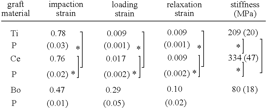
- After impaction, TiP formed a unified cylinder which maintained nicely it's shape. The firm entanglement of impacted TiP created homogeneous macroporous ‘cookies’ 107 which were very cohesive and could not be broken easily. Impacted specimens of BoP were less cohesive than specimens of TiP but stuck together after removal from the test chamber. Impacted CeP specimens tended to disintegrate after removal from the impaction chamber and fell apart quite easily.
- Mechanical Testing: Loading and Relaxation
- TiP
cookies 107 showed almost no deformation during physiological loading. At the end of the loading phase TiP specimens showed a strain of 0.009±0.001 (table 2). CeP deformed twice as much as TiP (loading strain 0.017±0.002). Compared to these synthetic grafts, BoP deformed considerably more and showed a loading strain of 0.29±0.05. This was significantly more than the other groups (p<0.001). - After a setting phase of about fifty loading cycles, stiffness remained almost unchanged during the rest of the loading period for all groups. There was a clear and significant difference between the three tested materials (table 2). TiP
cookies 107 showed an intermediate stiffness (209±20 MPa) and were about 2.5 times as stiff as BoP cookies (80±18 MPa, p<0.001). CeP cookies were about 4 times as stiff as BoP cookies (334±47 MPa, p<0.001) and therefore stiffer than TiP cookies (p<0.001). - After unloading the TiP cookies 107 (
FIG. 10B ) showed no residual deformation: relaxation strain was equal to loading strain (0.009±0.001). For the CeP cookies 107 (FIG. 10D ) only 50% of the loading strain recovered during the unloading phase (loading strain and relaxation strain 0.017±0.002 respectively 0.009±0.002). Although BoP specimens 107 (FIG. 10F ) showed a large relaxation strain of 0.10±0.02, this was still only one third of the loading strain (0.29±0.05). The fat that was forced out during cyclic loading, was partially resorbed back into the bone grafts during relaxation. The visco-elastic behaviour ofBoP cookies 107 during loading and subsequent relaxation is clearly apparent and shown inFIG. 12 . - Porous titanium particles which are impactible and adapt to defect geometry are provided according to the invention as graft material for application in impaction grafting. Like calciumphosphate, porous titanium in bulk application is an osteoconductive material. It provides good bony anchorage after implantation which may be farther enhanced by roughening or by application of a bioceramic coating such as calcium phosphate.
- Although constituted of pure metal, the compressibility of the highly porous titanium matrix of the
granules 13 was impressive. Unimpacted TiP can often be visibly deformed by forceful compression between two fingers. TiP deformed even more than BoP during impaction and created a firmly entangled graft layer. The combination of high impactability and firm entanglement can be important for the application in impaction grafting:granules 13 stick together well after only slight impaction and can be impacted further easily. Porosity of the titanium ‘cookies’ remained as high as 70-75% which is also a positive feature as there is ample interparticle space for tissue in-growth. Porous titanium particles are very ductile, have more rounded edges than CeP particles after compacting and can be gradually compressed. This will prevent the occurrence of high contact stresses as seen during the application of CeP in impaction grafting. - A layer of impacted TiP according to the invention is highly resistant to both compression and shear stress and allows only for small plastic deformation after reconstruction and in-vivo loading. This leads to excellent primary stability, which is a prerequisite in orthopedic surgery for tissue and especially bone ingrowth. With the confined compression test the resistance against compressive stress was tested. Impacted TiP were very resistant to compressive forces. TiP have the surprising characteristic of combining impactability and stability after impaction. Deformation of TiP during loading was very small and completely reversible during subsequent relaxation. As opposed to the synthetic materials TiP and CeP, BoP showed a considerable amount of displacement during loading despite realistic impaction: during loading the impacted BoP specimens lost about 25-30% of their original height and only one third of this deformation was corrected during elastic recovery. From observations made of impacted specimens, it appears that a reconstructive layer made from the highly entangled, almost unified impacted TiP will be much more shear resistant than a similar reconstructive layer made of BoP or any mixture of BoP and CeP
- It is generally accepted that plastic deformation imposes a thread on vitalization of the graft layer and that. However, some elastic deformation as allowed by the granules according to the invention appears to be beneficial for tissue in-growth and incorporation. Limited Axial micro motions during loading stimulate incorporation and ossification of bone grafts. A high stiffness of the graft material such as CeP prevents these micro motions and could prevent osseous differentiation of in-growing tissue by stress shielding. Impacted TiP particles are about as stiff as a 50/50 weight mix of bone graft and BoneSave® (217±14 MPa). Acetabular reconstructions made with a similar graft/BoneSave® mix (50/50 volume mix) showed good graft incorporation. TiP provides for a suitable alternative for such mixture and has better elasticity and impactability.
- In order to assess bone ingrowth after implantation holes were drilled in a bone in the knee area of a goat, which holes were filled with impacted TiP which was coated with a CaP (tricalcium phosphate/hydroxyapatite) coating with a mean thickness between 1 and 100 micrometer and impacted TiP without such coating respectively. Bone ingrowth was assessed after 4 weeks and after 12 weeks. The results are shown in table 3 below.
-
TABLE 3 4 weeks 12 weeks with coating 3.0 mm 3.2 mm without coating 0.6 mm 2.0 mm - From the test performed in vitro and visual inspections, compared to knowledge of the skilled person, it shows that the properties of TiP are superior to BoP and CeP in various aspects and that TiP is highly suitable for fixating prosthesis in human or animal bodies and for filling osseous defects.
- In
FIG. 1 afemur 1 is shown, in longitudinal section, of which the femoral head has been sawn off. In the embodiment shown inFIG. 1 a previously placed prosthesis or at least thefemoral part 2 thereof has been removed, for revision surgery. The present invention can be related to total hip arthroplasty (THA) or other prosthesis surgery, both in first placements and in revision surgery. InFIG. 1 anelongated hole 3 is shown, extending from the saw-offplane 4 along alongitudinal axis 5 of thefemur 1. Abone cement layer 6 extends along the inner surface of saidhole 3, which is closed off at thedistal end 7 by aplug 8. Thebone cement layer 6 is the remaining part of the bone cement used for the now removed femoral component of the previously used prosthesis. If the present invention is used for a first placement thehole 3 can be drilled and/or reamed into said bone in a known fashion. Thebone cement layer 6 abuts partly againstcortical bone 9 and/or againstspongeous bone 10. - In
FIG. 2 the cement is removed using appropriate tools such as a drill and/or reamer. - In
FIG. 3 , aguide wire 11 is driven into theplug 8, which guidewire 11 extends more or less parallel to thelongitudinal axis 5 of the femur, from saidplug 8 to aproximal end 12 outside saidhole 3. - In
FIG. 4 granules 13 are shown, deposited in thehole 3, resting against the inner wall orsurface 14 thereof and against theplug 8, thereby prevented from penetrating in the spongeous bone, marrow or other parts of the host. The type ofgranules 13, which are porous having interconnected pores, in this embodiment made by purification of titanium by titanium tetrachloride (TiCL4), will be discussed in greater detail later. Thegranules 13 preferably have been soaked in a fluid, prior to introduction thereof into saidhole 3, such that at least some of the fluid is adhered to the outer surface, which is relatively rough, whereas the pores thereof can be at least partly filled with said fluid. The fluid, for example a saline solution, has the advantage that the granules tend to stick together and are prevented from clinging to host tissue prior to impacting, as will be discussed. InFIG. 4A in an enlarged view a part of thegranules 13 is shown, positioned between theinner surface 14 of thehole 3 and theouter surface 15 of a compactingdevice 16 as is shown inFIG. 5 . - In
FIG. 5 acompacting device 16 is guided over theguide wire 11 and has anouter shape 17 that largely corresponds to the shape of thefemoral component 2 to be fixed in thefemur 1. Such guiding is known from for example U.S. Pat. No. 5,047,035. In cross section perpendicular to alongitudinal axis 18 of said compactingdevice 16 the surface area of each cross section is slightly larger than the surface area of a corresponding cross section of the femoral component to be placed, such that when the contours of said cross sections are interposed, as schematically shown inFIG. 5A for one level, the contour of the compacting device extends around and spaced apart from the contour of thefemoral component 3. - When the compacting
device 16 is driven into thegranules 13, as is shown inFIG. 5 , thegranules 13 are forced outward, in the direction of theinner surface 14 of thehole 3, and into each other. The force for driving the compacting device into the granules can be obtained by hammering, for example by hitting aproximal end 20 of the compactingdevice 16 with a hammer. The force exerted is an impact or impulse force, rather than a constant or smoothly increasing or decreasing pressure force. Due to the impact, the surface roughness of thegranules 13 and their mechanical flexibility, thegranules 13 will cling together strongly. If thegranules 13 have been soaked in a fluid such as water, the inter porosity is relatively large compared to inter porosity of identical granules impacted without being soaked prior to impact. The difference can for example be in the range of 8 to 12%. The fluid is at least partly forced out of the granules or the layer of granules by said impact and/or will drain from the granules and is absorbed by the host. - The granules have a surface roughness sufficient for them to cling together. Preferably the surface roughness is over 5.5 Ra, more specifically over 6 Ra. Very good results could be obtained with granules having a surface roughness of over 6.3 Ra.
- Preferably a
layer 21 ofgranules 13, interconnected, is formed against most and preferably all of saidinner wall 14 of thehole 3, having a thickness T of for example on average the equivalence of one to ten times the average size of the granules, as is shown inFIG. 6 .Such layer 21 can be obtained by forming in a number of subsequent steps of filling the space between theinner wall 13 and the compacting device partly, impacting, and then repeating said step, until theentire layer 21 is formed. The granules used can for example have an average size between 1 and 10 mm, at least for 50% of the total volume thereof. They can have an average size of between 2.5 and 7 mm, more preferably between 2.5 and 5.0 mm. All of the granules can have a size within one of said ranges. The size of the granules is defined by sieving. For example granules in the range between 3 and 5 mm can pass through a 5 mm sieve but not through a three mm sieve. Thegranules 13 can be provided with a coating, for example a bio-compatible, host tissue in-growth enhancing coating. The granules can be coated with a coating containing or existing of calcium phosphate. A layer of coating on the granules can have a thickness of between 0.5 and 100 micrometer. - After providing the
layer 21 ofgranules 13, whichlayer 21 is relatively form stable, the compactingdevice 16 and theguide wire 11 may be removed, leaving a void 22 above theplug 8, in which thestem 23 of a femoral component of a prosthesis can be positioned. Due to the difference in the sizes of the corresponding cross sections in the compactingdevice 16 and thestem 23 of thefemoral component 2 of the prosthesis, saidstem 23 can be positioned in saidvoid 22 with a slight distance D between the inner surface defined by the layer ofgranules 13 and the outer surface of thestem 23, which forms acontact surface 24 of thefemoral component 2. As is shown inFIG. 6 an amount ofbone cement 25 is poured or injected or otherwise provided in saidvoid 22, which amount is sufficient to fully cover the entire contact surface extending inside said void with a layer that is thicker than the said distance D between thegranules 13 and thecontact surface 24. The cement can be put under pressure before forcing the stem into the cement. When thestem 23 is forced into the void 22, as is shown inFIG. 7 , thebone cement 25 is forced up along thecontact surface 24 as well as partly into the pores between thegranules 13, filling the inter porosity. A small part of the bone cement might also enter pores ofgranules 13. InFIG. 7A on an enlarged scale part of theinner surface 14 and stem 23 are shown with the layer ofgranules 13 in between. As is shown the thickness Dg of thelayer 22 ofgranules 13 is smaller than the width W of the gap 26 between theinner wall 14 and thestem 23, the rest of said gap 26, which has a width Dc being filled with alayer 27 ofbone cement 25, which extends over a distance Dp into saidlayer 22 of granules. The distance Dc is preferably is between 1 and 4 times the average diameter of the granules, wherein the thickness of the cement layer is preferably at least approximately 2 mm in average, in order to prevent mechanical failure, and the cement preferably penetrates the layer of granules over a distance on average of approximately 2-x mm, wherein x represents the diameter of the largest granule used in the specific reconstruction. The thickness of the cement layer preferably is approximately constant over the contact surface of the prosthesis, such as the outer surface of a prosthesis fixation part such as a femoral stem or the outer surface of an acetabulum component, but may vary. - In a method and prosthesis fixation according to the present invention initial fixation of the prosthesis is mainly or at least to a large extend obtained by the granules being interconnected and compressed to the
inner wall 13 of thehole 3 in the host femur or other surface, and thebone cement 25 adhering to thegranules 13 and to thecontact surface 24 of the prosthesis. The granules having a relatively rough surface will inter alia mechanically cling together when compressed against each other. Thelayer 22 ofgranules 13 proved to have a high resistance to compression and probably to shear stress, whereas it allows small plastic deformation only after (reconstructive) surgery, during in vivo loading. This leads to a very high stability without the risk of lasting deformation of thelayer 22, resulting in high stability of the prosthesis fixation and reduced risk of fractures. The limited plastic deformation appears to improve bone and other host tissue in-growth. This may be the result of inter alia axial micro motions during loading, which could stimulate ossification of bone grafts, whereas the granules allow transduction of loading to in-growing tissue, due to the flexibility. - For performing a prosthesis surgery or filling operation according to the invention a kit can be used comprising at least a prosthesis and/or a mesh, porous granules having interconnected pores and bone cement, as well as an impacting device for impacting and compacting a layer of said granules. The granules may be coated and may be soaked. The impacting device, which can also be referred to as compacting device, can comprise at least a
stem part 23, which may consist of parts that can be used individually or in combination with each other. The stem preferably tapers slightly in the direction of a distal end, directed during used towards a side facing away from an impacting face, for forcing outward said granules. The kit can further comprise a plug with guide wire. Various compacting devices can be provided, for subsequent use, each following compacting device having for example a slightly larger cross section then the compacting device used in the previous step. The kit preferably comprises sufficient granules to cover a contact surface of the prosthesis or part thereof in the kit with a full layer of granules having a thickness at least one granule and preferably at least three granules. Furthermore it is advantageous when the amount of bone cement in the kit is sufficient to cover said layer of granules with a full layer of bone cement having a thickness comparable to the thickness of the layer of granules. - Prior to placement of the femoral stem the bone cement may to a very large extend or even completely fill the volume of the opening into which the stem is to be positioned. Upon positioning of the stem the cement will be pressurized inside said opening and the excess cement will be forced out at the proximal end. At an acetabulum component the entire opening of the acetabulum can be filled with cement, the excess cement being driven out upon placement of an acetabulum cup. The excess cement can then easily be removed. By way of example, which should not be explained limiting, for a THA (femoral and acetabular components) in a fully grown human being a quantity of about 75 grams of TiP (dry weight) with a porosity of 85-90% will have to be used.
- The
granules 13 preferably have a rough surface, such that granules poured loosely into a container will cling or adhere to each other mainly by surface particles of adjacent granules interconnecting. Granules made of ceramic material tend to break upon impacting, resulting in a poor stability and in small ceramic particles and debris which can roam freely, even into the surrounding host tissue, which can lead to health hazards. Porous metal granules according to the present invention prove to provide a more stable fixation than a similar use of BoP. - A realistic in-vivo THA was performed on three goats, using a method according to the present invention, as further elucidated by way of example with reference to
FIG. 1-7 , in which both the femoral and acetabular parts were replaced (total hip arthroplastic; THA) The goat weighed about 65 kg and 5-10 grams of TiP was used (dry weight) for fixation of the acetabulum. Directly after the operation the goat was placed in a hammock for ten days. From ten days after the operation the goats were allowed to load the prosthesis. After two weeks a level of titanium in the blood was measured below 10 ppb, which then decreased below 7 ppb, which is comparable to the concentration in a human being having a conventional well functioning Ti prosthesis. The TiP formed a stable reconstruction directly after the operation, which stability was maintained during three months after the operation. After three months the goat was euthanized and the prosthesis was visually inspected. Histology showed no signs of irritation, inflammation or foreign body reaction due to TiP, showing bio-compatibility. The prosthesis was fixated very good both by in-growth of fibrous tissue and bone tissue. Over the entire surface of thelayer 22 ofgranules 13 in-growth of tissue and/or bone appeared, whereas there was direct contact between the metal of thegranules 13 and the bone grown into thelayer 22. At several positions there was no contact between bone and granules, but there an interface was formed by said fibrous tissue. - In
FIG. 8 the filling of anosseous defect 28 is shown, usingparticles 13 which are impacted prior to and/or during placement in saiddefect 28, for example acavity 29 formed during removal of the old bone cement or resulting from bone resorption, removal of a tumor or other grounds. Thegranules 13 or acookie 107 formed thereof can be enclosed in saiddefect 28 by means of amesh 30 which closes off thecavity 29 but allows bone and/or tissue to grow through the mesh into the granules and/or bone cement to penetrate at least interporosity of thelayer 22 ofgranules 13. Thus relativelylarge cavities 29 can be filled and the anchorage of the filler can be obtained relatively easy, quick and firmly. - Acetabulum Components Experiment
-
FIG. 13A shows schematically atesting equipment 31, in which anacetabulum component 32 is positioned. A synthetic acetabulum model (Sawbones®) was used.FIGS. 13B and 13C show saidacetabulum component 32, which is e.g. a plastic such as polyethylene semi spherical cup, fixed in a hollow, semispherical chamber 33 of thetesting equipment 31 representing the acetabulum and having a radius of approximately 30 mm, using a layer ofTitanium granules 13 andbone cement 6. Thegranules 13 were poured in wet condition and impacted in saidchamber 33, using a semispherical compacting device 34 and a hammer, such that a hollow 34 was obtained having a radius of approximately 22.5 mm. The thickness of the layer ofgranules 13 was between 4 and 10 mm. The volume of the granules after impacting was about 55% of the volume prior to impacting. Acup 35 having a diameter of 42 mm was cemented into said hollow 34. Four groups of grafting materials were used, each in eightsuch testing devices 31, resulting in 32 testing devices. - Reconstructions were made with donor bone (I), donor bone mixed with Ti granules (II), Ti granules having a diameter between 3 and 5 mm (III) and Ti granules having a diameter between 4 and 7 mm (IV). All were used in the same testing device, using the same cement and the same dimensions. For using donor bone the instrumentation of Stryker was used. In reconstructions of group I 47.5 grams of donor bone was used, in group II 30 grams of Ti and 15 grams of donor bone was used, in group III and IV 37.5 grams of Ti granules was used.
- After a minimum of 48 hours after cementing the reconstruction was loaded and the displacement of the
cup 32 relative to the chamber 33 (acetabulum) due to loading was measured. The load was transferred to thecup 32 by using aspherical ball 35 as shown inFIG. 14 , fitting exactly in said cup (diameter of 28 mm) which was subjected to 900 loading cycles of 2-3000 N) having a frequency of 1 Hz and was applied by a servo-hydraulic MTS machine 35A (MTS® Systems Corporation, Minnesota, US). The position before and after said loading cycles was measured at a static load of 3000N and were compared. The displacement and rotation was measured in X, Y and Z direction and measured as (displ=displacement; rot=rotatie): -
Displacement: [(displX)2+(displY)2+(displZ)2]0.5 -
Rotation: [(rotX)2+(rotY)2+(rotZ)2]0.5 - In
FIG. 14A two diagrams are shown. The top diagram discloses displacement, the lower rotation for each of the groups I(B), II(TB), III(T3-5) and IV(T 4-7). These show that Ti provided the smallest displacement and rotation, although less grams are necessary wherein the smaller granules show the least displacement and rotation. The error beam shows the standard deviation within each group, smallest in the group III, the smallest granules. - After measurement of the displacement and rotation the sphere was removed and a
beam 36 was fixed in thecup 32 by screws as shown inFIG. 13B . Near thefree end 37 of said beam 36 awire 38 was fixed having a length direction substantially perpendicular to saidbeam 36 in a starting position as shown inFIG. 13A . Thewire 38 was retracted with a constant speed, the force F necessary was measured constantly over a trajectory of 10 cm. The maximum force Fmax over said trajectory was defined and multiplied with the distance between the point of connection of thewire 38 to thebeam 36 and the point of rotation of thecup 32, which was approximately 14 cm. This was defined as the lever-out-moment (LOM) In this test each of the test construction of groups I and II failed in the sense that thecup 32 was levered out of the acetabulum. Of group III three constructions failed, in group IV only two. InFIG. 14B the LOM of each group is shown, the error beam showing the standard deviation. The Ti granule groups clearly were superior to the bone graft groups I and II. - In a further test penetration of bone cement into the layer of
granules 13 was measured. From in vivo tests is has shown that cement penetration should be limited to a shallow depth in order to allow bone and other tissue to grow into said layer of granules. The penetration was measured by sawing a cup with the layer of granules in half along a mid section, as shown inFIG. 15 . A semi circle 39 was positioned along the outer surface of thecup 32, which was then divided into 49 sections of an 1.8 degree angle. In each section the distance from said semi circle 39 to the penultimate point of thecement layer 25 was measured in radial direction through said section. InFIG. 14C for each group I-IV the average penetration depth (left hand column; Sum of all penetration depths divided by 49) and the average variation of penetration (right hand column) is shown, wherein the error beams show the standard deviation. The penetration into Ti particle layers can be preferable over bone graft layers. - Bone Ingrowth Experiments in BCC
- In
FIG. 16 schematically a bone compaction chamber 40 (BCC; Aspenberg) is shown, which basically comprises two puretitanium half cylinders hexagonal cap 43 screwed over said halves. The twohalf cylinders pointy tip 44 andexternal screw thread 45 for screwing theBCC tip 44 first into bone B of a test bone, for example of an animal. Twoopenings 46 radially opposite each other and near said tip are provided for allowing growth of tissue into saidchamber 40 from the surrounding, as is shown byarrows 47. In experiments performed BCC were implanted in the proximal tibia of goats. The ingrowth openings 46 were positioned at the level of the endostium by adjusting thecap 43 which was kept outside thetibia 48. - Materials and Methods
- Six groups of BCC's were implanted: five groups filled with graft material and one empty control group (E). The five different graft materials consisted of four groups of porous titanium particles (TiP, Hereford Metal Powder Company Ltd, Hereford, UK) and one of impacted morsellized cancellous allograft bone particles (BoP) (Table 5 and 6).
-
TABLE 5 group graft material volume fraction (%) E — — B impacted cancellous allograft BoP 61 ± 9 T TiP. not coated, not impacted 22 ± 5 Ti TiP not coated, impacted 44 ± 2 Tc TiP. coated, not impacted 21 ± 5 Tci TiP. coated, impacted 40 ± 5 -
TABLE 6 graft group available for analysis bone ingrowth distance p value E 20 3.6 ± 2.0 <0.001 B 18 2.0 ± 1.0 — T 22 0.9 ± 1.0 0.12 Ti 22 0.6 ± 1.3 0.001 Tc 22 0.9 ± 0.9 0.02 Tci 22 0.8 ± 0.9 0.01 - A pool of cancellous allografts was obtained from freshly frozen (−40° C.) sternums of five goats that were nibbled with a rongeur to chips of about 1×2×2 mm after negative microbial culturing.
- TiP were rather spherical particles with a diameter of 1.0-1.4 mm that were constituted of commercially pure titanium and had pores ranging 10-150 μm. Backscatter scanning electron microscopy imaging (BEI, Jeol 6310, Jeol, Tokyo, Japan) and interactive computer controlled image analysis (AnalySIS®, Soft Imaging System GmbH, Munster, Germany) were used to determine the titanium volume fraction of individual particles, by determining the cross sectional porosity. TiP were cleaned ultrasonically with 10% Extran® MA01 (Merck KGaA., Darmstadt, Germany), 1 M HNO3, acetone and alcohol. In between these steps TiP were flushed and cleaned ultrasonically with demineralized water.
- The coating of TiP consisted of silicium dioxide containing calciumphosphate (HA:TCP 60:40) and was applied by DOT (BONITmatrix®, DOT GmbH, Rostock, Germany). Physicochemical analysis of TiP and coated TiP was performed with X-ray diffraction (XRD, with a thin-film Philips X-ray diffractometer, using Cu Kα-radiation (PW3710, 30 kV, 40 mA)) and with a scanning electron microscope (SEM, Jeol 6310, Jeol, Tokyo, Japan) which was equipped with an energy disperse X-ray detector (EDS). TiP showed a crystalline smooth surface before coating. After coating TiP were covered with dense ceramic granules with a mean diameter of about 5 μm. Coating increased the weight of TiP by 3.5%. XRD showed that the BONITmatrix® coating contained biphasic calciumphosphate (HA/TCP 60:40). EDS revealed the presence of calcium, phosphate, silicium (coating) and titanium (TiP) and a calcium over phosphate ratio of 1.4-1.5 and a calcium over silicium ratio of 1.3-1.4 (
FIG. 4 ). Coated TiP were subjected to X ray sterilization. Uncoated TiP were sterilized in an autoclave. - Impaction of allografts and titanium granules was standardized by dropping a weight of 9.8 g thirty times from a height of 33 cm along a sliding thread (Ø 2.0 mm, 9.8 g) which acts as an impactor to mimic manual impaction. Five specimens of every graft group, including five non impacted specimens of BoP, were not implanted but used for quantification of degree of impaction: specimens of BoP were prepared in stiff plastic tubes with an inner diameter of 2.0 mm, non implanted TiP specimens were prepared in BCC's. Cross sectional mineralized bone matrix area was determined from undecalcified central longitudinal slices (20 μm, Leica SP1600 saw-microtome, Leica Instruments GmbH, Nussloch, Germany) by light microscopy (Goldner staining). Cross sectional titanium area was determined by BEI from longitudinal cutted specimens after wet surface polishing (
grid 200, 400, 800, 1200, 2400). Bone volume fraction and titanium volume fraction were calculated with interactive computer controlled image analysis by dividing the mineralized bone matrix area respectively titanium area by the whole graft cylinder area. After impaction specimens were stored frozen (−40° C.) under sterile conditions and thawn before implantation. The mean distance between implanted chambers was 14 mm (12-19 mm). - Twelve Dutch milk goats (Capra Hircus Sanus) with a mean weight of 47 kg (38-59 kg) were operated after approval of the ethical committee on animal experiments. Animals were housed together in a climatologically controlled room at least one week prior to surgery (tenderfood bottom, 18-22° C.,
humidity 60%) and provided with fresh hay, concentrate, pulp and water. The goats were anesthetized with pentobarbital (1200 mg) and isoflurane. A longitudinal incision was used to expose bilaterally the proximal medial metaphysis of the tibia. After local excision of periosteum (biopsy punch Ø 6.0 mm, Stiefel Laboratorium GmbH, Offenbach am Main, Germany) a drilling and tapping guide block was fixated with k-wires. A measuring device was used for standardizing the distance between the mal and the anteromedial tibial plateau. Six BCC's were screwed into position in every tibia till the hexagonal cap made firm contact with the cortex. For closure of superficial fascia and skin a 2.0 monofilament suture was used. After the implantation procedure animals received subcutaneous ampicillin (Albipen LA, Intervet International BV, Boxmeer, The Netherlands) (15 mg/kg/48 h) three times. Pain medication consisted of flunixine (75 mg/24 h) three times and buprenorfine (0.3 mg/12 h) twice. - Fluorochromes were administered during three subsequent days at four weeks (tetracycline), eight weeks (calcein green) and twelve weeks (alizarine) after operation to observe time dependence of bone apposition. Goats were killed one day after administration of the last doses of alizarine with an overdose pentobarbital (2.4 g). BCC's with surrounding cortex were fixed in 4% buffered formalin. After three days the content was fixated additionally. Serial slices of 40 μm parallel to the longitudinal axis of the chamber were made of which three sections were used for histologic quantification: one central section and two peripheral sections (300 μm from the centre of the specimen).
- Fluorescence was classified subjectively by one person (LW) on an increasing 0-3 scale; 0: no fluorescence, 1: little fluorescence, some narrow bands, 2: clear fluorescence, intermediate apposition bands, 3: abundant fluorescence with broad apposition bands. Quantification of maximum bone ingrowth distance was done by another person (LD) by light microscopy (Goldner staining) and interactive computer controlled image analysis. Maximum bone ingrowth distance was defined as the largest distance between the bottom of the bone chamber and new bone in the graft cylinder, measured parallel to the longitudinal axis of the slice.
- Univariate analysis of variance was performed with the factors goat, implant position and graft group to analyze differences between groups in fluorochrome score and differences between groups in maximum bone ingrowth distance. Normality and homogenity of variance were tested using Kolmogorov-Smirnov's and Levene's test. Post-hoc t-tests (Tukey) were used to determine differences between groups. Statistical analysis was performed with SPSS 9.0 (SPSS Inc., Chicago, United States).
- The titanium volume fraction of individual TiP was 26±4%. Graft cylinders of unimpacted TiP (11-14 individual particles) showed a slightly lower titanium volume fraction. Impacted specimens consisted of 25-30 particles and showed a corresponding increase in titanium volume fraction. Titanium particles were slightly smaller than bone particles. About 15-18 bone chips could be impacted in the BCC which resulted in graft cylinders with a bone volume fraction of 61±9%. Impacted graft cylinders of both TiP and BoP were very dense. Longitudinal cross-sections of impacted TiP graft cylinders showed that only very small pores (10-50 μm) were visible in the center of TiP graft. Somewhat larger pores (50-75 μm) and openings between the TiP and the inner surface of the BCC could be found at the periphery (
FIG. 17 ). - All implantations were uneventful. One goat died five days after operation from sepsis from an intestinal clostridium infection. One of the goats suffered from a unilateral superficial wound infection which healed uneventful. Post-mortem X-rays twelve weeks after implantation showed cortical thickening and unchanged implant positions without any signs of fracture or osteolysis, corresponding to good fixation and no signs of infection as observed during harvesting of the BCC's.
- Six graft cylinders were damaged during histological preparation and therefore not available for histologic analysis (B: Two specimens, E: four specimens).
- Fluorescence scores were highest in groups B and E during the whole implantation period. After four weeks only little bone apposition was found in all graft groups (no significant differences in tetracyclin score). Most fluorochrome activity was seen four weeks later with significantly higher calcein scores in group B and E compared to groups Tc (p<0.05), Ti and Tci (p<0.001). At the end of implantation fluorochrome activity decreased. Alizarin score was significantly higher in groups B and E compared to groups T (p<0.05), Ti and Tci (p<0.01). Most bone ingrowth seemed to have incurred eight weeks after implantation. Between eight and twelve weeks there was a clear increase in bone apposition compared to the already observed bone quantity after eight weeks, but a smaller increase in bone ingrowth distance.
- In groups E and B a small cap of fibrous tissue preceded the invading bone, creating a fibrous transformation zone in graft cylinders of impacted bone chips. Fibrous tissue penetrated the whole graft cylinder of TiP up to the cap of the bone chamber in all specimens. The bone ingrowth front was quite fluent and easy to determine in empty BCC's and impacted BoP. However, bone ingrowth into TiP appeared to take place mainly in the periphery of graft cylinders, with some spots of bone formation in the more central part of the graft cylinder, especially in graft cylinders of impacted TiP.
- Maximum bone ingrowth distance was chosen instead of mean bone ingrowth distance like used previously in bone chamber studies. Maximum bone ingrowth distance after twelve weeks showed large variation within groups and was smaller in TiP than in impacted BoP or empty BCC's. Maximum bone ingrowth distance was highest in groups E and B: 3.6±2.0 mm respectively 2.0±1.0 mm, p<0.001 (Table 2). Bone ingrowth was significantly lower in all four groups of TiP compared to groups B (, p<0.05) and E (, p<0.001). Impacted TiP showed a trend towards smaller bone ingrowth distances in both coated and uncoated groups (p=0.2). Coated TiP did not seem to perform better than uncoated TiP (p=0.3). BEI/EDS did not show any signs of remnants of the Bonitmatrix® coating. Coated and non-coated TiP showed a comparable interface distribution in terms of presence/absence of direct contact between bone and titanium (
FIG. 11 ). - Corresponding to the in-vivo invasion of bone grafts, in the BCC ingrowing bone is preceded by ingrowing fibrous tissue which, besides improving tensile strength properties, almost doubles the compressive strength of impacted grafts four weeks after implantation. Although fibrous armoring may be sufficient for the long term stabilization of a reconstruction made with non-resorbable materials, the ingrowth of new bone seems preferable.
- The small quantity of bone ingrowth in unimpacted TiP can be a point of interest in this study as titanium is known to be osteoconductive and therefore TiP might be expected to even potentiate osteoconductivity of the BCC instead of impairing it.
- Several possible explanations could be given to explain the rather small bone ingrowth distance in TiP. The porosity of individual TiP was almost equal to the porosity of non impacted TiP graft cylinders. This indicates that deformation of TiP took place during manual insertion into BCC's.
- The heaping of TiP was more effective in the central part of the graft cylinder and less effective at the periphery where particles were in contact with the flat surrounding inner surface of the BCC. Although bone ingrowth was seen even into pores as small as 50 micrometer in TiP cylinders, a hypothesis of occlusion by impaction seems to be supported by the ingrowth pattern of bone which took mainly place at the periphery of TiP graft cylinders, especially in impacted specimens. Variation and range of ingrowth distances in TiP cylinders might indicate that in the presence of pores, TiP could demonstrate their osteoconductive potential.
- As seen in in-vivo reconstructions, impaction process results in quite porous graft layers which allow for penetration of bone cement, and individual bone chips and their macropores can often still be recognized.
- Slightly larger particles that still showed macropores were also completely compressed by the applied impaction procedure. Therefore the applied deformation might exceed clinical applied impaction. Over-impaction would not only jeopardize bone ingrowth in BoP but also osteoconduction of TiP.
- Addition of a CaP coating seemed to compensate to some extent the impairing effect of impaction of bone ingrowth.
- Bone in Growth in Ti Particles
- In table 4 six groups of grafts are shown, which were used in filling similar defects in a goats femurcondyl, in cylindrical defects. The defects had a diameter of 8 mm and a height of 10 mm, leading to a volume of 0.5 ml. All grafts were impacted as defined before. Uncoated Ti particles had a density of 0.5 g/ml (density A) The mass per defect was increased in case of coated particles, in order to maintain the Ti density similar in all defects. The TiPc1 coating was formed by calcium phosphate (tricalcium phosphate and hydroxyapetite) It made out approximately 7 weight % of the total mass. The coating of TiPc2 was calcium phosphate (carbonated apatite) and formed approximately 11 weight % of the total mass.
-
TABLE 4 groep partikel diameter (mm) grafts massa per defect (g) BoP 3-5 0.9 CeP 2-4 0.8 TiP 3-5 0.55 TiP/BoP 3-5 0.45/0.25 TiPc1 3-5 0.59 TiPc2 3-5 0.61 - With each
group 12 defects were filled in the femurcondyl of said goats, after which the in growth distance was defined after 4 and 12 weeks by sawing the bone across (perpendicular to the length direction) showing substantially circular cross sections of the filled defects. Each circle was divided into four quarts, and the in growth was defined in each quart as the radial distance of in growth, after which the average in growth was defined as the average of these four quarts. InFIG. 20 a cross section is shown with acircle 50 drawn in, indicating the outer periphery of the defect, and four quadrants 51, each showing an arrow 52 indicating the in growth distance. Titanium in the defect is shown in black, bone in grey. InFIG. 20A a diagram is shown in which for the groups of grafts defined in table 3 the average in growth is shown after 4 weeks and 12 weeks. This clearly shown that for these samples and defects the in growth distance for uncoated TiP is smallest after 4 weeks but comparable to said distance of the coated TiP grafts after 12 weeks and slightly smaller than in BoP and CeP. - Goat Tests
- A large load bearing defect (segmental and cavitary) in the acetabulum of 10 goats was reconstructed with a wire mesh and with TiP.
- One goat failed because of a femoral fracture not related to the acetabular reconstruction. In one goat a luxation of the cup was found but the Tip layer was intact. In one goat the cup was loose upon offering but again the TiP layer was intact. Macroscopically the cement had penetrated the layer of TiP. After 15 weeks fluorochrome labels showed abundant new bone formation had taken place in the layer of TiP of all goats. In some goats the new bone formation was found up to the interface with the cement layer. In most areas no soft tissue interface or a very thin soft tissue interface was present between the layer of TiP and the cement layer. The blood levels of Ti during the follow up period were low. In the thick sections no accumulations of Ti debris was present in any of the goats.
- Large defect in the acetabulum of goats can be reconstructed with impacted TiP. The soft tissue interface is thinner than in similar previous experiments in the same model in which the same defect was reconstructed with MCB or a mixture of MCB with TCP/HA layer.
- In the present study we reconstructed the same defect with impacted layer of titanium particles (TiP). The main questions addressed were the extent of bone ingrowths into the layer of TiP, the nature of the interface between TiP layer and the cement layer, the potential generation of small Ti particles in the reconstruction, and the Ti blood levels.
- Materials and Methods
- Animal Model
- The study was performed on 10 adult female Dutch milk goats (Capra Hircus Sana). All animals were skeletally mature and weighed between 50 and 60 kg (mean 55 kg). The follow up period was 15 weeks.
- Materials
- Titanium Particles (porosity of 75-80% %, diameter of 2.8-4 mm) were provided by Fondel Finance BV (Rotterdam, the Netherlands). Al TiP particles were cleaned according to the protocols for clinical use by Cam Implants BV (Leiden, the Netherlands). All TiP were coated with a layer of calcium phosphate according to the method previously published by Kukubo (Yan W Q, Nakamura T, Kawanabe K, Nishigochi S, Oka M, Kokubo T. Apatite layer-coated titanium for use as bone bonding implants. Biomaterials 1997; 18:1185-1190). The coating has been applied by Biomaterialen, Radbout University, Nijmegen).
- Surgical Procedure
- Pre-operatively, an antibiotic injection (Baytril 0.2 ml/kg; Bayer, Division Animal Health, Mijdrecht, the Netherlands) was administered intramuscularly. Pre-operative pain management consisted of intramuscular administration of both buprenorphine hydrochloride (
Temgesic 5 μg/kg; Renckitt Benkiser Healthcare, Hull, United Kingdom) and a non-steroidal anti-inflammatory drug, fluxin meglumine (Finadyne 1 mg/kg; Schering-Plough Animal Health, Brussels, Belgium). Intra-operatively, the pain suppression was maintained further by an intra-venous injection of sodiumpentobarbital (Nembutal 30 mg/kg; Ceva Sante Animale, Maassluis, the Netherlands). Surgery was performed with the animals lying on their left side using isoflurane anesthesia (2.5% isoflurane on a oxygen/nitro-oxygen mixture). The incision site was shaved and thoroughly cleaned with betadine. Thereafter, a C-shaped incision was used to approach the right hip from the anterior side. The gluteal muscles were partially loosened from the femur and retracted. The capsule was opened with a T-shaped incision and thereafter the femoral head was dislocated. Next, a femoral neck osteotomy was performed. The acetabulum was reamed up to a diameter of 32 mm and using a high speed power drill, the superolateral rim was removed to simulate a segmental defect as observed frequently in hip revision surgery. The resultingtype 3 AAOS segmental defect was reconstructed with a metal mesh (X-Change metal mesh, Stryker Orthopedics, Newbury, United Kingdom) which was secured to the outer side of the pelvic bone with four AO bone screws (diameter 3.5 mm; length of 10 or 20 mm; Synthes, Switzerland). Small burr holes (2 mm) were made in the dense bone areas of the acetabulum wall to facilitate vascularization of the bone graft. After a trial testing of the cup, the defect was reconstructed with TiP. Ca. 5-11 grams of TiP was used for each reconstruction. Several dome shaped impactors varying in size from 26 mm to 32 mm and comparable to the Acetabular X-change® revision set (Stryker Orthopedics, Newbury, United Kingdom) were used for impaction. The inner diameter of the reconstructed defect was 32 mm in diameter. Next, bone cement (Surgical Simplex-P, Stryker Orthopedics, Newbury, United Kingdom) was introduced into thedefect 4 minutes after mixing the powder with the monomer and thereafter pressurized for two minutes. A custom made Exeter sheep polyethylene cup (inner diameter 22.2 mm,outer diameter 29 mm) was inserted 6 minutes after mixing. Next, the femoral shaft was opened and cleared with broaches. The femoral canal was ravaged and bone cement was injected retrograde 3.5 minutes after mixing the bone cement components. A double-tapered polished V40 Exeter sheep stem (Stryker, Benoist Girard, France) was inserted 5 minutes after mixing the bone cement. After setting of the cement, the hip was reduced. The soft tissues were closed in layers and a control X-ray was made of the hip region. Postoperatively, the animals were placed in a hammock forca 10 to 14 days. They received ampicilline antibiotics (Albipen LA 15 mg/kg; Intervet, Boxmeer, the Netherlands) for another 48 hours and also intramuscular injections of Finadyne (4 days) and Temgesic (2 days) for pain suppression. Afterwards, the goats were housed in an out door farm with ample space to walk around. Each goat received a subcutaneous injection of calcein green solution (25 mg/kg) at 8 and 1 days before killing to allow histological assessment of bone formation at the time of offering. - The goats received fluorochromes during the follow up period (Tetracycline, calcein green and xylenol orange) and they were killed at 15 weeks postoperatively, with an overdose of barbiturate (
Nembutal 60 mg/kg). Standard roentgen photographs were taken from the implant sites to verify the implant position and to exclude fractures and dislocations. Both the femur and the reconstructed acetabulum were harvested, cleaned from all soft tissue and fixed in a 4% buffered formaldehyde solution at 4° C. for at least ten days. - Histology
- After making contact X-ray photos of the retrieved hip components, the reconstructed acetabular defects were macroscopically dissected into several parts according to the two halves. All parts were dehydrated and embedded non-decalcified in polymethylmethacrylate (PMMA) and serial sectioned at a Leica SP1600 saw-microtome, Heidelberg, Germany, sections circa 50 microns thickness). Sections were inspected non-stained. After quantification of bone ingrowth they were HE-stained or left unstained for the visualization of calcein fluorescence. All sections were observed under ordinary and fluorescent light.
- In one section of every specimen the thickness of the interface was measured at five locations at equal distance from each other. To determine the location where measurements were carried out a tangent was drawn along the acetabulum. From the center of the cup five lines at equal corners (30 degrees) were drawn and at the intersections with the soft tissue interface measurements were carried out. All values of one goat were averaged.
- Clinical Observations and Complications.
- One goat broke his femur, which was a complication after surgery and which was probably not directly related to the reconstructive surgery. During the first two weeks after release from the hammock all goats limped, but thereafter it improved to almost normal walking in all animals. One cup was completely loose upon offering and one cup was slightly loose.
- Histological Analysis.
- Based on the thick sections (
FIG. 21-23 ). In all specimens the layer of TiP had been integrated into the host bone (FIG. 24 ). Bone was intimately connected to the outer layer of the TiP layer (FIG. 22 ). In all specimens a considerable ingrowth of new bone was found in the larger voids in-between individual TiP granules (FIG. 23 ). - Fibrous Tissue Formation.
- In most specimens new bone had reached the TiP cement interface (
FIG. 23 ). The interface between TiP and cement was rather tight and in most cases a direct connection was found between TiP layer and cement (FIG. 23 ). In some locations a relatively thin fibrous tissue interface was found that was in general thinner then 100 microns (FIG. 23 ). This is substantially smaller than was expected and smaller than when using bone graft. - Ti Levels in Blood.
- Preoperative TiP ion levels were ca 0.6 PPB. During the follow up period this level slowly increased to ca 1.0 PPB (
FIG. 25 ), which was surprisingly low. - In previous publications on the model used to test TCP/HA MCB mixture, the main complication was a fracture of the acetabular wall. The fracture of the medial wall is related to the goat model. After reaming with a 32 mm reamer to create a reproducible cavitary defect, especially in some goats with smaller bone dimensions, the medial wall is extremely thin. During the impaction process with TCP/HA the thin medial wall is fractured in these cases. In this series no perforation of the medial wall was observe. This can be related to the impactability of TiP, which can lead to a more homogeneous distribution of stresses over the medial wall bone.
- A second observation in this model was that in all three studies performed previously a relatively thick interface developed between the incorporated bone graft and the cement layer (Arts J J, Gardeniers J W, Welten M L, Verdonschot N, Schreurs B W, Buma P. No negative effects of bone impaction grafting with bone and ceramic mixtures. Clin Orthop 2005; 438:239-247; Buma P, Arts J J, Gardeniers J W, Verdonschot N, Schreurs B W. No effect of bone morphogenetic protein-7 (OP-1) on the incorporation of impacted bone grafts in a realistic acetabular model. J Biomed Mater Res B Appl Biomater 2007; Schimmel J W, Buma P, Versleyen D, Huiskes R, Slooff T J. Acetabular reconstruction with impacted morselized cancellous allografts in cemented hip arthroplasty: a histological and biomechanical study on the goat. J Arthroplasty 1998; 13:438-448). In contrast, in this study no or only a very thin layer of fibrous tissue is present between the TiP layer and cement. Probably the soft tissue interface is formed in the process in which the MCB is desorbed. Potentially this leads to a weakening of the remodelling graft layer and cement. In case of TiP layer the integrity of the TiP cement layer can be strengthened by the ingrowth of bone. No weakening by remodelling shall occur which might explain the very favourable results with respect to interface development.
- Finally Ti levels were lower then in clinical series in which ti non-cemented implants were used (
FIG. 25 ). - In conclusion, the results of this animal experiment are favourable. Bone ingrowths in all reconstructions were found. Even in goats in which the cup had been luxated or was loose, an intact layer of TiP was found.
- The present invention is by no means limited to the embodiments shown and described. Many variations are possible within the scope of protection claimed by the claims. It should especially be noted that the method or a kit of parts according to the invention can be used in other parts of the human or animal body, for example for different prosthesis. TiP may be mixed with for example BoP and/or CeP but preferably only TiP are used. A prosthesis if applicable can have any desired shape and size. These alternatives are also considered to be covered by the scope of the appending claims.
Claims (35)
Applications Claiming Priority (3)
| Application Number | Priority Date | Filing Date | Title |
|---|---|---|---|
| NL1032851 | 2006-11-10 | ||
| NL1032851A NL1032851C2 (en) | 2006-11-10 | 2006-11-10 | Kit and method for fixing a prosthesis or part thereof and / or filling bony defects. |
| PCT/NL2007/050560 WO2008056987A2 (en) | 2006-11-10 | 2007-11-12 | Kit and method for fixating a prosthesis or part thereof and/or filling osseous defects |
Related Parent Applications (1)
| Application Number | Title | Priority Date | Filing Date |
|---|---|---|---|
| PCT/NL2007/050560 Continuation WO2008056987A2 (en) | 2006-11-10 | 2007-11-12 | Kit and method for fixating a prosthesis or part thereof and/or filling osseous defects |
Publications (2)
| Publication Number | Publication Date |
|---|---|
| US20090306673A1 true US20090306673A1 (en) | 2009-12-10 |
| US8361161B2 US8361161B2 (en) | 2013-01-29 |
Family
ID=38364613
Family Applications (1)
| Application Number | Title | Priority Date | Filing Date |
|---|---|---|---|
| US12/463,038 Expired - Fee Related US8361161B2 (en) | 2006-11-10 | 2009-05-08 | Kit and method for fixating a prosthesis or part thereof and/or filling osseous defects |
Country Status (7)
| Country | Link |
|---|---|
| US (1) | US8361161B2 (en) |
| EP (1) | EP2083761A2 (en) |
| JP (1) | JP2010508954A (en) |
| CN (1) | CN101616643A (en) |
| NL (1) | NL1032851C2 (en) |
| RU (1) | RU2458655C2 (en) |
| WO (1) | WO2008056987A2 (en) |
Cited By (6)
| Publication number | Priority date | Publication date | Assignee | Title |
|---|---|---|---|---|
| US20090228114A1 (en) * | 2008-02-29 | 2009-09-10 | Ron Clark | Femoral Prosthesis |
| US20130333482A1 (en) * | 2012-06-13 | 2013-12-19 | Sheng-Chih CHANG | Compression Testing Device |
| WO2014152113A3 (en) * | 2013-03-14 | 2014-12-24 | Prosidyan, Inc. | Bioactive porous composite bone graft implants |
| WO2014152102A3 (en) * | 2013-03-14 | 2015-02-12 | Prosidyan, Inc. | Bioactive porous bone graft implants |
| US20150289979A1 (en) * | 2012-11-09 | 2015-10-15 | Karl Leibinger Medizintechnik Gmbh & Co. Kg | Bone implant made of at least two different absorbable and biodegradable materials adapted to be combined as hybrid or composite material |
| US9237989B2 (en) | 2009-05-28 | 2016-01-19 | Taragenyx Limited | Coating method |
Families Citing this family (10)
| Publication number | Priority date | Publication date | Assignee | Title |
|---|---|---|---|---|
| NL1032851C2 (en) | 2006-11-10 | 2008-05-14 | Fondel Finance B V | Kit and method for fixing a prosthesis or part thereof and / or filling bony defects. |
| SE531319C2 (en) | 2007-02-22 | 2009-02-24 | Tigran Technologies Ab Publ | Porous implant granule |
| GB0918484D0 (en) * | 2009-10-22 | 2009-12-09 | Depuy Int Ltd | A medical implant device |
| US8585770B2 (en) * | 2011-07-12 | 2013-11-19 | Biomet Manufacturing, Llc | Implant sleeve for cement hip stems |
| ITUD20120059A1 (en) * | 2012-04-06 | 2013-10-07 | Limacorporate Spa | PROSTHETIC ELEMENT FOR BONE ENDS WHAT FINGERS OR TEETH AND ITS RELATION PROCEDURE |
| CN102698316B (en) * | 2012-05-16 | 2014-08-13 | 华东理工大学 | Rapid-curing adhesive bone repair material and preparation method thereof |
| RU2550974C1 (en) * | 2014-02-21 | 2015-05-20 | Государственное бюджетное образовательное учреждение высшего профессионального образования "Самарский государственный медицинский университет" Министерства здравоохранения Российской Федерации | Method of estimating osteointegration of porous wire materials in experiment |
| CN104323875B (en) * | 2014-10-14 | 2017-01-18 | 刘振东 | Bone grafting device for repairing large segmental bone defects |
| RU2698872C2 (en) * | 2017-12-28 | 2019-08-30 | Общество с ограниченной ответственностью "ОСТЕОМЕД-М" (ООО "ОСТЕОМЕД-М") | Device for fixing bone fragments with high tibial corrective osteotomy |
| RU2696243C2 (en) * | 2017-12-28 | 2019-07-31 | Общество с ограниченной ответственностью "ОСТЕОМЕД-М" (ООО "ОСТЕОМЕД-М") | Kit for high tibial osteotomy and method of correction of varus strain of knee joint by means of mini-invasive operation |
Citations (124)
| Publication number | Priority date | Publication date | Assignee | Title |
|---|---|---|---|---|
| US3855638A (en) * | 1970-06-04 | 1974-12-24 | Ontario Research Foundation | Surgical prosthetic device with porous metal coating |
| US4146936A (en) * | 1975-12-30 | 1979-04-03 | Sumitomo Chemical Company Limited | Implants for bones, joints and tooth roots |
| US4202055A (en) * | 1976-05-12 | 1980-05-13 | Battelle-Institut E.V. | Anchorage for highly stressed endoprostheses |
| US4281420A (en) * | 1979-02-15 | 1981-08-04 | Raab S | Bone connective prostheses adapted to maximize strength and durability of prostheses-bone cement interface; and methods of forming same |
| US4283799A (en) * | 1979-09-10 | 1981-08-18 | Massachusetts Institute Of Technology | Pre-coated body implant |
| US4344190A (en) * | 1979-07-25 | 1982-08-17 | University Of Exeter | Plugs for the medullary canal of a bone |
| US4355428A (en) * | 1976-07-02 | 1982-10-26 | S.A. Benoist Girard & Cie | Surgical prosthesis with grainy surface |
| US4365358A (en) * | 1978-08-18 | 1982-12-28 | Judet Robert | Joint prostheses, particularly in hip prostheses |
| US4454612A (en) * | 1980-05-07 | 1984-06-19 | Biomet, Inc. | Prosthesis formation having solid and porous polymeric components |
| US4483799A (en) * | 1980-02-08 | 1984-11-20 | Agfa-Gevaert Aktiengesellschaft | Hydroxy alkane sulfonic acid sulfoalkyl esters |
| US4497075A (en) * | 1979-10-08 | 1985-02-05 | Mitsubishi Mining & Cement Co., Ltd. | Filler for filling in defects or hollow portions of bones |
| US4612160A (en) * | 1984-04-02 | 1986-09-16 | Dynamet, Inc. | Porous metal coating process and mold therefor |
| US4644942A (en) * | 1981-07-27 | 1987-02-24 | Battelle Development Corporation | Production of porous coating on a prosthesis |
| US4673409A (en) * | 1984-04-25 | 1987-06-16 | Minnesota Mining And Manufacturing Company | Implant with attachment surface |
| US4693721A (en) * | 1984-10-17 | 1987-09-15 | Paul Ducheyne | Porous flexible metal fiber material for surgical implantation |
| US4713076A (en) * | 1984-04-19 | 1987-12-15 | Klaus Draenert | Coating composition and anchorage component for surgical implants |
| US4735625A (en) * | 1985-09-11 | 1988-04-05 | Richards Medical Company | Bone cement reinforcement and method |
| US4737411A (en) * | 1986-11-25 | 1988-04-12 | University Of Dayton | Controlled pore size ceramics particularly for orthopaedic and dental applications |
| US4738681A (en) * | 1985-07-10 | 1988-04-19 | Harrington Arthritis Research Center | Femoral-joint prosthetic device |
| US4755184A (en) * | 1986-01-09 | 1988-07-05 | Mark Silverberg | Bone augmentation implant |
| US4888024A (en) * | 1985-11-08 | 1989-12-19 | Powlan Roy Y | Prosthetic device and method of fixation within the medullary cavity of bones |
| US4919673A (en) * | 1988-02-29 | 1990-04-24 | Sulzer Brothers Limited | Prosthesis for a femoral head |
| US5007931A (en) * | 1990-05-04 | 1991-04-16 | Boehringer Mannheim Corporation | Porous coated prosthesis |
| US5015256A (en) * | 1987-03-30 | 1991-05-14 | Ab Idea | Method and means for fixing a joint prosthesis |
| US5034186A (en) * | 1985-11-20 | 1991-07-23 | Permelec Electrode Ltd. | Process for providing titanium composite having a porous surface |
| US5047035A (en) * | 1990-08-10 | 1991-09-10 | Mikhail Michael W E | System for performing hip prosthesis revision surgery |
| US5133771A (en) * | 1990-12-05 | 1992-07-28 | University Of British Columbia | Flexible mold for forming composite of a hip replacement component and a bone cement sleeve |
| US5171275A (en) * | 1990-02-15 | 1992-12-15 | Ling Robin S M | Femoral stem prosthesis |
| US5178201A (en) * | 1991-03-05 | 1993-01-12 | Eska Medical Gmbh & Co. | Method for producing an implant with an open-celled metal structure |
| US5192324A (en) * | 1982-02-18 | 1993-03-09 | Howmedica Inc. | Bone prosthesis with porous coating |
| US5197990A (en) * | 1990-05-17 | 1993-03-30 | Howmedica International, Inc. | Prosthetic intramedullary femoral prosthesis with preformed sheath |
| US5314493A (en) * | 1992-09-10 | 1994-05-24 | Mikhail Michael W E | Femoral hip joint prosthesis |
| US5336263A (en) * | 1992-04-06 | 1994-08-09 | Robert A. Ersek | Treatment of urological and gastric fluid reflux disorders by injection of mmicro particles |
| US5343877A (en) * | 1992-09-09 | 1994-09-06 | University Of Iowa Research Foundation | Orthopedic implant and method |
| US5383932A (en) * | 1993-04-27 | 1995-01-24 | Johnson & Johnson Professional, Inc. | Absorbable medullary plug |
| US5405389A (en) * | 1992-02-19 | 1995-04-11 | Joint Medical Products Corporation | Sintered coatings for implantable prostheses |
| US5425768A (en) * | 1993-03-08 | 1995-06-20 | Carpenter; Charles W. | Reinforced spacer for stem-type prosthetic implants |
| US5433750A (en) * | 1992-03-14 | 1995-07-18 | Eska Medical Gmbh & Co. | Bone replacement with different regions of porosities |
| US5489306A (en) * | 1995-01-03 | 1996-02-06 | Gorski; Jerrold M. | Graduated porosity implant for fibro-osseous integration |
| US5504300A (en) * | 1994-04-18 | 1996-04-02 | Zimmer, Inc. | Orthopaedic implant and method of making same |
| US5507815A (en) * | 1991-06-17 | 1996-04-16 | Cycam, Inc. | Random surface protrusions on an implantable device |
| US5571182A (en) * | 1988-12-12 | 1996-11-05 | Ersek; Robert A. | Textured micro implants |
| US5645593A (en) * | 1994-04-12 | 1997-07-08 | Corin Medical Limited | Prosthesis component |
| US5665121A (en) * | 1992-02-03 | 1997-09-09 | Howmedica International | Preformed mantle |
| US5676700A (en) * | 1994-10-25 | 1997-10-14 | Osteonics Corp. | Interlocking structural elements and method for bone repair, augmentation and replacement |
| US5734959A (en) * | 1995-10-12 | 1998-03-31 | Zimmer, Inc. | Method of making an orthopaedic implant having a porous surface using an organic binder |
| US5782917A (en) * | 1996-02-26 | 1998-07-21 | Sunmed, Inc. | Intramedullary bone plug |
| US5855612A (en) * | 1995-05-12 | 1999-01-05 | Ohta Inc. | Biocompatible titanium implant |
| US5861042A (en) * | 1990-09-17 | 1999-01-19 | Buechel; Frederick F. | Prosthesis with biologically inert wear resistant surface |
| US5868796A (en) * | 1990-09-17 | 1999-02-09 | Buechel; Fredrick F. | Prosthesis with biologically inert wear resistant surface |
| US5976188A (en) * | 1997-10-21 | 1999-11-02 | Johnson & Johnson Professional, Inc. | Modular prosthesis system with hybrid fixation |
| US6008432A (en) * | 1997-10-01 | 1999-12-28 | Osteonics Corp. | Metallic texture coated prosthetic implants |
| US6066176A (en) * | 1996-07-11 | 2000-05-23 | Oshida; Yoshiki | Orthopedic implant system |
| US6087553A (en) * | 1996-02-26 | 2000-07-11 | Implex Corporation | Implantable metallic open-celled lattice/polyethylene composite material and devices |
| US6120544A (en) * | 1997-05-16 | 2000-09-19 | Eska Implants Gmbh & Co. | Femur endoprosthesis for articial hip joint |
| US6193761B1 (en) * | 1995-07-07 | 2001-02-27 | Depuy Orthopaedics, Inc. | Implantable prosthesis with metallic porous bead preforms applied during casting |
| US6206924B1 (en) * | 1999-10-20 | 2001-03-27 | Interpore Cross Internat | Three-dimensional geometric bio-compatible porous engineered structure for use as a bone mass replacement or fusion augmentation device |
| US6214053B1 (en) * | 1998-06-04 | 2001-04-10 | Benoist Girard Sas | Prosthesis with centralizer and centralizer for use therewith |
| US20010004711A1 (en) * | 1994-11-30 | 2001-06-21 | Richard J. Lazzara | Infection-blocking dental implant |
| US20010004712A1 (en) * | 1998-06-04 | 2001-06-21 | Robin Sydney Mackwood Ling | Prosthesis provided with a mantle |
| US6395327B1 (en) * | 1999-03-12 | 2002-05-28 | Zimmer, Inc. | Enhanced fatigue strength orthopaedic implant with porous coating and method of making same |
| US6497728B2 (en) * | 2000-02-16 | 2002-12-24 | Korea Advanced Institute Of Science And Technology | Metal jacket for a cementless artificial joint stem and artificial joint having the jacket |
| US20030004578A1 (en) * | 2001-06-28 | 2003-01-02 | Ethicon, Inc. | Composite scaffold with post anchor for the repair and regeneration of tissue |
| US6524344B2 (en) * | 2000-02-16 | 2003-02-25 | Korea Advanced Institute Of Science And Technology | Cement jacket for a cemented artificial joint stem and artificial joint having the cement jacket |
| US20030055511A1 (en) * | 2000-03-03 | 2003-03-20 | Schryver Jeffrey E. | Shaped particle comprised of bone material and method of making the particle |
| US6537320B1 (en) * | 1998-10-30 | 2003-03-25 | Gary K. Michelson | Self-broaching, rotatable, push-in interbody spinal fusion implant and method for deployment thereof |
| US20030060873A1 (en) * | 2001-09-19 | 2003-03-27 | Nanomedical Technologies, Inc. | Metallic structures incorporating bioactive materials and methods for creating the same |
| US6565606B1 (en) * | 1998-09-09 | 2003-05-20 | Lanka Limited | Implant, method of making the same and use the same |
| US6582470B1 (en) * | 1996-01-22 | 2003-06-24 | Etex Corporation | Surface modification of medical implants |
| US20030163205A1 (en) * | 2002-02-27 | 2003-08-28 | Lawson Kevin Jon | Arthroplasty-prothesis cement restrictor |
| US20040019132A1 (en) * | 2001-02-23 | 2004-01-29 | Marc Long | Bone graft substitutes |
| US6699288B2 (en) * | 2000-03-22 | 2004-03-02 | Scolio Gmbh | Cage-type intervertebral implant |
| US20040107002A1 (en) * | 2002-11-18 | 2004-06-03 | Toshinobu Katsuya | Distal tip for the positioning of artificial joint stem |
| US6746488B1 (en) * | 2002-03-19 | 2004-06-08 | Biomet, Inc. | Method and apparatus for hindering osteolysis in porous implants |
| US20040157952A1 (en) * | 2001-05-30 | 2004-08-12 | Renzo Soffiati | Bone cement containing coated radiopaque particles and its preparation |
| US20050013973A1 (en) * | 2001-01-19 | 2005-01-20 | Richter Paul Wilhelm | Implant |
| US20050027366A1 (en) * | 2003-04-30 | 2005-02-03 | Therics, Inc. | Bone void filler and method of manufacture |
| US20050112397A1 (en) * | 2003-07-24 | 2005-05-26 | Rolfe Jonathan L. | Assembled non-random foams |
| US20050123672A1 (en) * | 2003-12-03 | 2005-06-09 | Justin Daniel F. | Laser based metal deposition of implant structures |
| US20050129778A1 (en) * | 2003-08-06 | 2005-06-16 | Nirmal Mulye | Pharmaceutical composition containing water soluble drug |
| US20050159820A1 (en) * | 2002-05-13 | 2005-07-21 | Hideki Yoshikawa | Member for regenerating joint cartilage and process for producing the same, method of regenerating joint cartilage and artificial cartilage for transplantation |
| US20050165494A1 (en) * | 2002-04-29 | 2005-07-28 | Fondel Finance B.V. | Prosthesis fixation with mechanically compacted biocompatible granules |
| US20050161120A1 (en) * | 2003-06-13 | 2005-07-28 | Yukiharu Hasegawa | Orthopedic and dental endosseous implants and their preparation method |
| US6979336B2 (en) * | 2002-03-26 | 2005-12-27 | Depuy Orthopaedics, Inc. | System and method for delivering biological materials to a prosthesis implantation site |
| US6981991B2 (en) * | 2002-06-27 | 2006-01-03 | Ferree Bret A | Arthroplasty devices configured to reduce shear stress |
| US20060015187A1 (en) * | 2004-07-19 | 2006-01-19 | Smith & Nephew Inc. | Pulsed current sintering for surfaces of medical implants |
| US20060078847A1 (en) * | 2000-09-29 | 2006-04-13 | Kwan Norman H | Dental implant system and additional methods of attachment |
| US7044978B2 (en) * | 2003-10-27 | 2006-05-16 | Zimmer Technology, Inc. | Positioner and method for a femoral hip implant |
| US7048870B1 (en) * | 1993-12-20 | 2006-05-23 | Astrazeneca Ab | Metallic implant and process for treating a metallic implant |
| US7052518B2 (en) * | 2002-03-19 | 2006-05-30 | Olympus Corporation | Artificial bone and tissue engineering carrier |
| US7056577B1 (en) * | 1999-04-28 | 2006-06-06 | Tigran Technologies Ab | Body for providing ingrowth and growth of bone tissue and/or connective tissue and method of making such a body |
| US20060122706A1 (en) * | 2003-05-15 | 2006-06-08 | Lo Wei J | Synthetic bone graft biomaterial |
| US20060129161A1 (en) * | 2001-01-25 | 2006-06-15 | Tecomet, Inc. | Textured surface having undercut micro recesses in a surface |
| US7211113B2 (en) * | 2004-05-18 | 2007-05-01 | Lev Zelener | Hip prosthesis |
| US7229478B2 (en) * | 1997-01-31 | 2007-06-12 | Medidea, Llc | Shoulder prosthesis with anatomic reattachment features |
| US20070173952A1 (en) * | 2003-11-27 | 2007-07-26 | Doxa Ab | Implant and method of producing the same, and a system for implantation |
| US7258810B2 (en) * | 2001-12-06 | 2007-08-21 | Smith & Nephew, Inc. | In-situ oxidized textured surfaces for prosthetic devices and method of making same |
| US20080011613A1 (en) * | 2004-07-21 | 2008-01-17 | Rizhi Wang | Method of electrolytically depositing a pharmaceutical coating onto a conductive osteal implant |
| US7368065B2 (en) * | 2005-06-23 | 2008-05-06 | Depuy Products, Inc. | Implants with textured surface and methods for producing the same |
| US7393361B2 (en) * | 2004-02-20 | 2008-07-01 | Spinecore, Inc. | Artificial intervertebral disc having a bored semispherical bearing with a compression locking post and retaining caps |
| US7491219B2 (en) * | 1995-09-04 | 2009-02-17 | Active Implants Corporation | Method and apparatus for computerized surgery |
| US7501073B2 (en) * | 2003-02-24 | 2009-03-10 | Depuy Products, Inc. | Methods for producing metallic implants having roughened surfaces |
| US20090112315A1 (en) * | 2007-10-29 | 2009-04-30 | Zimmer, Inc. | Medical implants and methods for delivering biologically active agents |
| US7534451B2 (en) * | 2004-02-03 | 2009-05-19 | Orthovita, Inc. | Bone restorative carrier mediums |
| US7550009B2 (en) * | 2004-03-08 | 2009-06-23 | Impliant Ltd. | Spinal prosthesis |
| US20090162235A1 (en) * | 2005-12-05 | 2009-06-25 | Mitsubishi Materials Corporation | Medical device and surface modification method for medical device |
| US7563286B2 (en) * | 2002-08-15 | 2009-07-21 | Synthes Usa, Llc | Controlled artificial intervertebral disc implant |
| US20090187256A1 (en) * | 2008-01-21 | 2009-07-23 | Zimmer, Inc. | Method for forming an integral porous region in a cast implant |
| US20090192610A1 (en) * | 2008-01-30 | 2009-07-30 | Zimmer, Inc. | Orthopedic component of low stiffness |
| US7635447B2 (en) * | 2006-02-17 | 2009-12-22 | Biomet Manufacturing Corp. | Method and apparatus for forming porous metal implants |
| US7648735B2 (en) * | 2003-12-16 | 2010-01-19 | Smith & Nephew, Inc. | Oxidized zirconium on a porous structure for bone implant use |
| US20100075419A1 (en) * | 2006-09-26 | 2010-03-25 | Masahiko Inagaki | Biomaterial, method of constructing the same and use thereof |
| US20100094430A1 (en) * | 2006-10-12 | 2010-04-15 | Susan Pran Krumdieck | Device |
| US20100121463A1 (en) * | 2005-04-27 | 2010-05-13 | Bioretec Oy | Bioabsorbable and bioactive composite material and a method for manufacturing the composite |
| US20100131074A1 (en) * | 2005-09-13 | 2010-05-27 | Takiron Co., Ltd. | Composite porous object |
| US20100168869A1 (en) * | 2008-12-31 | 2010-07-01 | Howmedica Osteonics Corp. | Tissue integration implant |
| US20100179667A1 (en) * | 2009-01-15 | 2010-07-15 | The Curators Of The University Of Missouri | Scaffold for bone and tissue repair in mammals |
| US7842095B2 (en) * | 2007-09-11 | 2010-11-30 | Howmedica Osteonics Corp. | Antibiotic bone cement spacer |
| US20110022181A1 (en) * | 2008-01-28 | 2011-01-27 | Ngk Spark Plug Co., Ltd. | Article with foamed surface, implant and method of producing the same |
| US20110022180A1 (en) * | 2009-07-24 | 2011-01-27 | Warsaw Orthopedic, Inc. | Implantable medical devices |
| US7993402B2 (en) * | 2004-07-14 | 2011-08-09 | Hkross AG | Filler, supply device and method for forming a support structure in a bone cavity |
| US8066778B2 (en) * | 2005-04-21 | 2011-11-29 | Biomet Manufacturing Corp. | Porous metal cup with cobalt bearing surface |
| US8075680B2 (en) * | 2007-02-09 | 2011-12-13 | Alma Mater Studiorum-Universitá Di Bologna | Dental cement |
| US8197550B2 (en) * | 2005-04-21 | 2012-06-12 | Biomet Manufacturing Corp. | Method and apparatus for use of porous implants |
Family Cites Families (56)
| Publication number | Priority date | Publication date | Assignee | Title |
|---|---|---|---|---|
| DE2305441A1 (en) * | 1973-02-03 | 1974-08-08 | Rosenthal Stemag Tech Keramik | TENSIONER CONNECTION FOR IMPLANTS |
| US4888022A (en) * | 1985-12-30 | 1989-12-19 | Huebsch Donald L | Endoprosthesis |
| DE58902022D1 (en) * | 1988-04-22 | 1992-09-17 | Mathys Ag | MARKER ROOM LOCK. |
| CH680564A5 (en) * | 1989-12-07 | 1992-09-30 | Experimentelle Chirurgie Schwe | |
| US5258030A (en) * | 1991-07-08 | 1993-11-02 | The Trustees Of The University Of Pennsylvania | Porous coated implants |
| DE4143453C2 (en) * | 1991-07-11 | 1997-09-11 | Haerle Anton | Centering element for bone implants |
| US5340362A (en) * | 1991-10-16 | 1994-08-23 | Carbone John J | Method and apparatus for cementing intramedullary bone prosthesis |
| US5681572A (en) * | 1991-10-18 | 1997-10-28 | Seare, Jr.; William J. | Porous material product and process |
| SE469653B (en) * | 1992-01-13 | 1993-08-16 | Lucocer Ab | POROEST IMPLANT |
| US5358533A (en) * | 1992-02-19 | 1994-10-25 | Joint Medical Products Corporation | Sintered coatings for implantable prostheses |
| US5954771A (en) * | 1993-02-16 | 1999-09-21 | Wright Medical Technology, Inc. | Dual fixation prosthesis |
| US5947893A (en) * | 1994-04-27 | 1999-09-07 | Board Of Regents, The University Of Texas System | Method of making a porous prothesis with biodegradable coatings |
| DE4424883A1 (en) * | 1994-07-14 | 1996-01-18 | Merck Patent Gmbh | Femoral prosthesis |
| US7494507B2 (en) * | 2000-01-30 | 2009-02-24 | Diamicron, Inc. | Articulating diamond-surfaced spinal implants |
| RU2114580C1 (en) * | 1995-05-29 | 1998-07-10 | Открытое акционерное общество "Композит" | Endoprosthesis of knee-joint |
| US5658338A (en) * | 1995-09-29 | 1997-08-19 | Tullos; Hugh S. | Prosthetic modular bone fixation mantle and implant system |
| US6149689A (en) * | 1995-11-22 | 2000-11-21 | Eska Implants Gmbh & Co. | Implant as bone replacement |
| US6143948A (en) * | 1996-05-10 | 2000-11-07 | Isotis B.V. | Device for incorporation and release of biologically active agents |
| US6136038A (en) * | 1996-12-30 | 2000-10-24 | Xenon Research, Inc. | Bone connective prosthesis and method of forming same |
| US5935169A (en) * | 1997-02-13 | 1999-08-10 | Chan; Kwan-Ho | Bone cement plug for deployment in a bone canal |
| JP4491076B2 (en) * | 1997-03-27 | 2010-06-30 | スミス アンド ネフュー インコーポレーテッド | Zirconium alloy surface oxidation method and product by this method |
| US6123731A (en) * | 1998-02-06 | 2000-09-26 | Osteotech, Inc. | Osteoimplant and method for its manufacture |
| US6736849B2 (en) * | 1998-03-11 | 2004-05-18 | Depuy Products, Inc. | Surface-mineralized spinal implants |
| US6261322B1 (en) * | 1998-05-14 | 2001-07-17 | Hayes Medical, Inc. | Implant with composite coating |
| US7553329B2 (en) * | 1999-08-18 | 2009-06-30 | Intrinsic Therapeutics, Inc. | Stabilized intervertebral disc barrier |
| TW491714B (en) * | 1999-12-08 | 2002-06-21 | Wen-Jing Shiue | Orthopedic implant having a porous surface and method of making same |
| AU1979201A (en) * | 1999-12-09 | 2001-06-18 | Bio Syntech Canada Inc | Mineral-polymer hybrid composition |
| EP1255515B1 (en) * | 2000-02-18 | 2008-06-11 | IsoTis N.V. | Plug for insertion into a bone canal |
| DE50103053D1 (en) * | 2000-03-01 | 2004-09-09 | Sulzer Orthopedics Ltd | Cemented stem prosthesis |
| US9050192B2 (en) * | 2001-02-05 | 2015-06-09 | Formae, Inc. | Cartilage repair implant with soft bearing surface and flexible anchoring device |
| AU2002245702A1 (en) * | 2001-03-19 | 2002-10-03 | Cambridge Polymer Group Inc. | System and methods for reducing interfacial porosity in cements |
| US7695521B2 (en) * | 2001-05-01 | 2010-04-13 | Amedica Corporation | Hip prosthesis with monoblock ceramic acetabular cup |
| US7291178B2 (en) * | 2001-05-29 | 2007-11-06 | Mediteam Dental Ab | Modified oxide |
| US6478825B1 (en) * | 2001-11-28 | 2002-11-12 | Osteotech, Inc. | Implant, method of making same and use of the implant for the treatment of bone defects |
| US6926741B2 (en) * | 2002-01-25 | 2005-08-09 | Depuy Products, Inc. | Centralizing cement plug with countersink |
| US20030176921A1 (en) * | 2002-03-13 | 2003-09-18 | Lawson Kevin Jon | Two-part prosthetic nucleus replacement for surgical reconstruction of intervertebral discs |
| EP1369095A3 (en) * | 2002-06-04 | 2004-01-14 | MTF MediTech Franken GmbH | Method and device for moistening a medical implant or graft |
| US7048767B2 (en) * | 2002-06-11 | 2006-05-23 | Spire Corporation | Nano-crystalline, homo-metallic, protective coatings |
| NL1021137C2 (en) * | 2002-07-23 | 2004-01-27 | Fondel Finance B V | Support element for attachment to bone. |
| CA2416348C (en) * | 2003-01-14 | 2009-09-01 | Michael Lococo | Bone implant and device for forming a socket for same |
| GB0304168D0 (en) * | 2003-02-24 | 2003-03-26 | Benoist Girard Sas | Surface treatment of metal |
| US20040243133A1 (en) * | 2003-03-05 | 2004-12-02 | Therics, Inc. | Method and system for manufacturing biomedical articles, such as using biomedically compatible infiltrant metal alloys in porous matrices |
| RU2240744C1 (en) * | 2003-08-04 | 2004-11-27 | Государственное образовательное учреждение высшего профессионального образования Санкт-Петербургская государственная медицинская академия им. И.И. Мечникова | Method for fixing femoral component of hip joint's prosthesis |
| EP1537839A1 (en) * | 2003-12-02 | 2005-06-08 | Dr. h. c. Robert Mathys Foundation | Prosthetic device for cartilage repair |
| US7364592B2 (en) * | 2004-02-12 | 2008-04-29 | Dexcom, Inc. | Biointerface membrane with macro-and micro-architecture |
| US7083651B2 (en) * | 2004-03-03 | 2006-08-01 | Joint Synergy, Llc | Spinal implant |
| US20080188857A1 (en) * | 2004-09-21 | 2008-08-07 | Lars Bruce | Method and Device For Improving the Fixing of a Prosthesis |
| SE530144C2 (en) * | 2004-09-21 | 2008-03-11 | Tigran Technologies Ab | Fixing device for elongate prosthesis has vibrating tool with head that oscillates back and forth about swiveling axis, with tool axis coinciding with longitudinal axis of prosthesis |
| US20060229715A1 (en) * | 2005-03-29 | 2006-10-12 | Sdgi Holdings, Inc. | Implants incorporating nanotubes and methods for producing the same |
| US7871561B2 (en) * | 2005-03-31 | 2011-01-18 | Japan Science And Technology Agency | Artificial bone and method for producing the same |
| US20060235541A1 (en) * | 2005-04-15 | 2006-10-19 | Zimmer Technology, Inc. | Bearing implant |
| NL1029017C2 (en) * | 2005-05-11 | 2006-11-14 | Fondel Finance B V | Molded product and mass and method for manufacturing thereof. |
| RU2284788C1 (en) * | 2005-05-30 | 2006-10-10 | Геннадий Львович Плоткин | Method for setting hip joint endoprosthesis pedicle |
| US7828805B2 (en) * | 2006-02-02 | 2010-11-09 | Zimmer Technology, Inc. | Hip stem centralizer datum guide, and method |
| NL1032851C2 (en) | 2006-11-10 | 2008-05-14 | Fondel Finance B V | Kit and method for fixing a prosthesis or part thereof and / or filling bony defects. |
| US8828088B2 (en) * | 2007-11-08 | 2014-09-09 | Linares Medical Devices, Llc | Joint assembly incorporating undercut surface design to entrap accumulating wear debris from plastic joint assembly |
-
2006
- 2006-11-10 NL NL1032851A patent/NL1032851C2/en not_active IP Right Cessation
-
2007
- 2007-11-12 CN CN200780049563A patent/CN101616643A/en active Pending
- 2007-11-12 JP JP2009536184A patent/JP2010508954A/en active Pending
- 2007-11-12 WO PCT/NL2007/050560 patent/WO2008056987A2/en active Application Filing
- 2007-11-12 RU RU2009121707/14A patent/RU2458655C2/en not_active IP Right Cessation
- 2007-11-12 EP EP07834688A patent/EP2083761A2/en not_active Withdrawn
-
2009
- 2009-05-08 US US12/463,038 patent/US8361161B2/en not_active Expired - Fee Related
Patent Citations (129)
| Publication number | Priority date | Publication date | Assignee | Title |
|---|---|---|---|---|
| US3855638A (en) * | 1970-06-04 | 1974-12-24 | Ontario Research Foundation | Surgical prosthetic device with porous metal coating |
| US4146936A (en) * | 1975-12-30 | 1979-04-03 | Sumitomo Chemical Company Limited | Implants for bones, joints and tooth roots |
| US4202055A (en) * | 1976-05-12 | 1980-05-13 | Battelle-Institut E.V. | Anchorage for highly stressed endoprostheses |
| US4355428A (en) * | 1976-07-02 | 1982-10-26 | S.A. Benoist Girard & Cie | Surgical prosthesis with grainy surface |
| US4365358A (en) * | 1978-08-18 | 1982-12-28 | Judet Robert | Joint prostheses, particularly in hip prostheses |
| US4281420A (en) * | 1979-02-15 | 1981-08-04 | Raab S | Bone connective prostheses adapted to maximize strength and durability of prostheses-bone cement interface; and methods of forming same |
| US4344190A (en) * | 1979-07-25 | 1982-08-17 | University Of Exeter | Plugs for the medullary canal of a bone |
| US4283799A (en) * | 1979-09-10 | 1981-08-18 | Massachusetts Institute Of Technology | Pre-coated body implant |
| US4497075A (en) * | 1979-10-08 | 1985-02-05 | Mitsubishi Mining & Cement Co., Ltd. | Filler for filling in defects or hollow portions of bones |
| US4483799A (en) * | 1980-02-08 | 1984-11-20 | Agfa-Gevaert Aktiengesellschaft | Hydroxy alkane sulfonic acid sulfoalkyl esters |
| US4454612A (en) * | 1980-05-07 | 1984-06-19 | Biomet, Inc. | Prosthesis formation having solid and porous polymeric components |
| US4644942A (en) * | 1981-07-27 | 1987-02-24 | Battelle Development Corporation | Production of porous coating on a prosthesis |
| US5192324A (en) * | 1982-02-18 | 1993-03-09 | Howmedica Inc. | Bone prosthesis with porous coating |
| US4612160A (en) * | 1984-04-02 | 1986-09-16 | Dynamet, Inc. | Porous metal coating process and mold therefor |
| US4713076A (en) * | 1984-04-19 | 1987-12-15 | Klaus Draenert | Coating composition and anchorage component for surgical implants |
| US4673409A (en) * | 1984-04-25 | 1987-06-16 | Minnesota Mining And Manufacturing Company | Implant with attachment surface |
| US4693721A (en) * | 1984-10-17 | 1987-09-15 | Paul Ducheyne | Porous flexible metal fiber material for surgical implantation |
| US4738681A (en) * | 1985-07-10 | 1988-04-19 | Harrington Arthritis Research Center | Femoral-joint prosthetic device |
| US4735625A (en) * | 1985-09-11 | 1988-04-05 | Richards Medical Company | Bone cement reinforcement and method |
| US4888024A (en) * | 1985-11-08 | 1989-12-19 | Powlan Roy Y | Prosthetic device and method of fixation within the medullary cavity of bones |
| US5034186A (en) * | 1985-11-20 | 1991-07-23 | Permelec Electrode Ltd. | Process for providing titanium composite having a porous surface |
| US4755184A (en) * | 1986-01-09 | 1988-07-05 | Mark Silverberg | Bone augmentation implant |
| US4737411A (en) * | 1986-11-25 | 1988-04-12 | University Of Dayton | Controlled pore size ceramics particularly for orthopaedic and dental applications |
| US5015256A (en) * | 1987-03-30 | 1991-05-14 | Ab Idea | Method and means for fixing a joint prosthesis |
| US4919673A (en) * | 1988-02-29 | 1990-04-24 | Sulzer Brothers Limited | Prosthesis for a femoral head |
| US5571182A (en) * | 1988-12-12 | 1996-11-05 | Ersek; Robert A. | Textured micro implants |
| US5171275A (en) * | 1990-02-15 | 1992-12-15 | Ling Robin S M | Femoral stem prosthesis |
| US5007931A (en) * | 1990-05-04 | 1991-04-16 | Boehringer Mannheim Corporation | Porous coated prosthesis |
| US5197990A (en) * | 1990-05-17 | 1993-03-30 | Howmedica International, Inc. | Prosthetic intramedullary femoral prosthesis with preformed sheath |
| US5192283A (en) * | 1990-08-10 | 1993-03-09 | Ling Robin S M | System for performing hip prosthesis revision surgery |
| US5047035A (en) * | 1990-08-10 | 1991-09-10 | Mikhail Michael W E | System for performing hip prosthesis revision surgery |
| US5868796A (en) * | 1990-09-17 | 1999-02-09 | Buechel; Fredrick F. | Prosthesis with biologically inert wear resistant surface |
| US5861042A (en) * | 1990-09-17 | 1999-01-19 | Buechel; Frederick F. | Prosthesis with biologically inert wear resistant surface |
| US5133771A (en) * | 1990-12-05 | 1992-07-28 | University Of British Columbia | Flexible mold for forming composite of a hip replacement component and a bone cement sleeve |
| US5178201A (en) * | 1991-03-05 | 1993-01-12 | Eska Medical Gmbh & Co. | Method for producing an implant with an open-celled metal structure |
| US5507815A (en) * | 1991-06-17 | 1996-04-16 | Cycam, Inc. | Random surface protrusions on an implantable device |
| US5665121A (en) * | 1992-02-03 | 1997-09-09 | Howmedica International | Preformed mantle |
| US5405389A (en) * | 1992-02-19 | 1995-04-11 | Joint Medical Products Corporation | Sintered coatings for implantable prostheses |
| US5433750A (en) * | 1992-03-14 | 1995-07-18 | Eska Medical Gmbh & Co. | Bone replacement with different regions of porosities |
| US5336263A (en) * | 1992-04-06 | 1994-08-09 | Robert A. Ersek | Treatment of urological and gastric fluid reflux disorders by injection of mmicro particles |
| US5343877A (en) * | 1992-09-09 | 1994-09-06 | University Of Iowa Research Foundation | Orthopedic implant and method |
| US5314493A (en) * | 1992-09-10 | 1994-05-24 | Mikhail Michael W E | Femoral hip joint prosthesis |
| US5425768A (en) * | 1993-03-08 | 1995-06-20 | Carpenter; Charles W. | Reinforced spacer for stem-type prosthetic implants |
| US5383932A (en) * | 1993-04-27 | 1995-01-24 | Johnson & Johnson Professional, Inc. | Absorbable medullary plug |
| US7048870B1 (en) * | 1993-12-20 | 2006-05-23 | Astrazeneca Ab | Metallic implant and process for treating a metallic implant |
| US5645593A (en) * | 1994-04-12 | 1997-07-08 | Corin Medical Limited | Prosthesis component |
| US5504300A (en) * | 1994-04-18 | 1996-04-02 | Zimmer, Inc. | Orthopaedic implant and method of making same |
| US5676700A (en) * | 1994-10-25 | 1997-10-14 | Osteonics Corp. | Interlocking structural elements and method for bone repair, augmentation and replacement |
| US20010004711A1 (en) * | 1994-11-30 | 2001-06-21 | Richard J. Lazzara | Infection-blocking dental implant |
| US5489306A (en) * | 1995-01-03 | 1996-02-06 | Gorski; Jerrold M. | Graduated porosity implant for fibro-osseous integration |
| US5855612A (en) * | 1995-05-12 | 1999-01-05 | Ohta Inc. | Biocompatible titanium implant |
| US6193761B1 (en) * | 1995-07-07 | 2001-02-27 | Depuy Orthopaedics, Inc. | Implantable prosthesis with metallic porous bead preforms applied during casting |
| US7491219B2 (en) * | 1995-09-04 | 2009-02-17 | Active Implants Corporation | Method and apparatus for computerized surgery |
| US5734959A (en) * | 1995-10-12 | 1998-03-31 | Zimmer, Inc. | Method of making an orthopaedic implant having a porous surface using an organic binder |
| US6582470B1 (en) * | 1996-01-22 | 2003-06-24 | Etex Corporation | Surface modification of medical implants |
| US5782917A (en) * | 1996-02-26 | 1998-07-21 | Sunmed, Inc. | Intramedullary bone plug |
| US6087553A (en) * | 1996-02-26 | 2000-07-11 | Implex Corporation | Implantable metallic open-celled lattice/polyethylene composite material and devices |
| US6066176A (en) * | 1996-07-11 | 2000-05-23 | Oshida; Yoshiki | Orthopedic implant system |
| US7229478B2 (en) * | 1997-01-31 | 2007-06-12 | Medidea, Llc | Shoulder prosthesis with anatomic reattachment features |
| US6120544A (en) * | 1997-05-16 | 2000-09-19 | Eska Implants Gmbh & Co. | Femur endoprosthesis for articial hip joint |
| US6008432A (en) * | 1997-10-01 | 1999-12-28 | Osteonics Corp. | Metallic texture coated prosthetic implants |
| US5976188A (en) * | 1997-10-21 | 1999-11-02 | Johnson & Johnson Professional, Inc. | Modular prosthesis system with hybrid fixation |
| US20010004712A1 (en) * | 1998-06-04 | 2001-06-21 | Robin Sydney Mackwood Ling | Prosthesis provided with a mantle |
| US6214053B1 (en) * | 1998-06-04 | 2001-04-10 | Benoist Girard Sas | Prosthesis with centralizer and centralizer for use therewith |
| US6565606B1 (en) * | 1998-09-09 | 2003-05-20 | Lanka Limited | Implant, method of making the same and use the same |
| US6537320B1 (en) * | 1998-10-30 | 2003-03-25 | Gary K. Michelson | Self-broaching, rotatable, push-in interbody spinal fusion implant and method for deployment thereof |
| US6395327B1 (en) * | 1999-03-12 | 2002-05-28 | Zimmer, Inc. | Enhanced fatigue strength orthopaedic implant with porous coating and method of making same |
| US20020151983A1 (en) * | 1999-03-12 | 2002-10-17 | Shetty H. Ravindranath | Enhanced fatigue strength orthopaedic implant with porous coating and method of making same |
| US7553539B2 (en) * | 1999-04-28 | 2009-06-30 | Tigran Technologies Ab | Grain for providing cell growth |
| US7056577B1 (en) * | 1999-04-28 | 2006-06-06 | Tigran Technologies Ab | Body for providing ingrowth and growth of bone tissue and/or connective tissue and method of making such a body |
| US6206924B1 (en) * | 1999-10-20 | 2001-03-27 | Interpore Cross Internat | Three-dimensional geometric bio-compatible porous engineered structure for use as a bone mass replacement or fusion augmentation device |
| US6524344B2 (en) * | 2000-02-16 | 2003-02-25 | Korea Advanced Institute Of Science And Technology | Cement jacket for a cemented artificial joint stem and artificial joint having the cement jacket |
| US6497728B2 (en) * | 2000-02-16 | 2002-12-24 | Korea Advanced Institute Of Science And Technology | Metal jacket for a cementless artificial joint stem and artificial joint having the jacket |
| US20030055511A1 (en) * | 2000-03-03 | 2003-03-20 | Schryver Jeffrey E. | Shaped particle comprised of bone material and method of making the particle |
| US6699288B2 (en) * | 2000-03-22 | 2004-03-02 | Scolio Gmbh | Cage-type intervertebral implant |
| US20060078847A1 (en) * | 2000-09-29 | 2006-04-13 | Kwan Norman H | Dental implant system and additional methods of attachment |
| US20050013973A1 (en) * | 2001-01-19 | 2005-01-20 | Richter Paul Wilhelm | Implant |
| US20060129161A1 (en) * | 2001-01-25 | 2006-06-15 | Tecomet, Inc. | Textured surface having undercut micro recesses in a surface |
| US20040019132A1 (en) * | 2001-02-23 | 2004-01-29 | Marc Long | Bone graft substitutes |
| US20040157952A1 (en) * | 2001-05-30 | 2004-08-12 | Renzo Soffiati | Bone cement containing coated radiopaque particles and its preparation |
| US20030004578A1 (en) * | 2001-06-28 | 2003-01-02 | Ethicon, Inc. | Composite scaffold with post anchor for the repair and regeneration of tissue |
| US20030060873A1 (en) * | 2001-09-19 | 2003-03-27 | Nanomedical Technologies, Inc. | Metallic structures incorporating bioactive materials and methods for creating the same |
| US7258810B2 (en) * | 2001-12-06 | 2007-08-21 | Smith & Nephew, Inc. | In-situ oxidized textured surfaces for prosthetic devices and method of making same |
| US20030163205A1 (en) * | 2002-02-27 | 2003-08-28 | Lawson Kevin Jon | Arthroplasty-prothesis cement restrictor |
| US7052518B2 (en) * | 2002-03-19 | 2006-05-30 | Olympus Corporation | Artificial bone and tissue engineering carrier |
| US6746488B1 (en) * | 2002-03-19 | 2004-06-08 | Biomet, Inc. | Method and apparatus for hindering osteolysis in porous implants |
| US6979336B2 (en) * | 2002-03-26 | 2005-12-27 | Depuy Orthopaedics, Inc. | System and method for delivering biological materials to a prosthesis implantation site |
| US20050165494A1 (en) * | 2002-04-29 | 2005-07-28 | Fondel Finance B.V. | Prosthesis fixation with mechanically compacted biocompatible granules |
| US20050159820A1 (en) * | 2002-05-13 | 2005-07-21 | Hideki Yoshikawa | Member for regenerating joint cartilage and process for producing the same, method of regenerating joint cartilage and artificial cartilage for transplantation |
| US6981991B2 (en) * | 2002-06-27 | 2006-01-03 | Ferree Bret A | Arthroplasty devices configured to reduce shear stress |
| US7563286B2 (en) * | 2002-08-15 | 2009-07-21 | Synthes Usa, Llc | Controlled artificial intervertebral disc implant |
| US20040107002A1 (en) * | 2002-11-18 | 2004-06-03 | Toshinobu Katsuya | Distal tip for the positioning of artificial joint stem |
| US7501073B2 (en) * | 2003-02-24 | 2009-03-10 | Depuy Products, Inc. | Methods for producing metallic implants having roughened surfaces |
| US7857860B2 (en) * | 2003-04-30 | 2010-12-28 | Therics, Llc | Bone void filler and method of manufacture |
| US20050027366A1 (en) * | 2003-04-30 | 2005-02-03 | Therics, Inc. | Bone void filler and method of manufacture |
| US20060122706A1 (en) * | 2003-05-15 | 2006-06-08 | Lo Wei J | Synthetic bone graft biomaterial |
| US20050161120A1 (en) * | 2003-06-13 | 2005-07-28 | Yukiharu Hasegawa | Orthopedic and dental endosseous implants and their preparation method |
| US7208222B2 (en) * | 2003-07-24 | 2007-04-24 | Viasys Healthcare Inc. | Assembled non-random foams |
| US20050112397A1 (en) * | 2003-07-24 | 2005-05-26 | Rolfe Jonathan L. | Assembled non-random foams |
| US20050129778A1 (en) * | 2003-08-06 | 2005-06-16 | Nirmal Mulye | Pharmaceutical composition containing water soluble drug |
| US7044978B2 (en) * | 2003-10-27 | 2006-05-16 | Zimmer Technology, Inc. | Positioner and method for a femoral hip implant |
| US20070173952A1 (en) * | 2003-11-27 | 2007-07-26 | Doxa Ab | Implant and method of producing the same, and a system for implantation |
| US20050123672A1 (en) * | 2003-12-03 | 2005-06-09 | Justin Daniel F. | Laser based metal deposition of implant structures |
| US7648735B2 (en) * | 2003-12-16 | 2010-01-19 | Smith & Nephew, Inc. | Oxidized zirconium on a porous structure for bone implant use |
| US7534451B2 (en) * | 2004-02-03 | 2009-05-19 | Orthovita, Inc. | Bone restorative carrier mediums |
| US7393361B2 (en) * | 2004-02-20 | 2008-07-01 | Spinecore, Inc. | Artificial intervertebral disc having a bored semispherical bearing with a compression locking post and retaining caps |
| US7550009B2 (en) * | 2004-03-08 | 2009-06-23 | Impliant Ltd. | Spinal prosthesis |
| US7211113B2 (en) * | 2004-05-18 | 2007-05-01 | Lev Zelener | Hip prosthesis |
| US7993402B2 (en) * | 2004-07-14 | 2011-08-09 | Hkross AG | Filler, supply device and method for forming a support structure in a bone cavity |
| US20060015187A1 (en) * | 2004-07-19 | 2006-01-19 | Smith & Nephew Inc. | Pulsed current sintering for surfaces of medical implants |
| US20080011613A1 (en) * | 2004-07-21 | 2008-01-17 | Rizhi Wang | Method of electrolytically depositing a pharmaceutical coating onto a conductive osteal implant |
| US8066778B2 (en) * | 2005-04-21 | 2011-11-29 | Biomet Manufacturing Corp. | Porous metal cup with cobalt bearing surface |
| US8197550B2 (en) * | 2005-04-21 | 2012-06-12 | Biomet Manufacturing Corp. | Method and apparatus for use of porous implants |
| US20100121463A1 (en) * | 2005-04-27 | 2010-05-13 | Bioretec Oy | Bioabsorbable and bioactive composite material and a method for manufacturing the composite |
| US7368065B2 (en) * | 2005-06-23 | 2008-05-06 | Depuy Products, Inc. | Implants with textured surface and methods for producing the same |
| US20100131074A1 (en) * | 2005-09-13 | 2010-05-27 | Takiron Co., Ltd. | Composite porous object |
| US20090162235A1 (en) * | 2005-12-05 | 2009-06-25 | Mitsubishi Materials Corporation | Medical device and surface modification method for medical device |
| US7635447B2 (en) * | 2006-02-17 | 2009-12-22 | Biomet Manufacturing Corp. | Method and apparatus for forming porous metal implants |
| US20100075419A1 (en) * | 2006-09-26 | 2010-03-25 | Masahiko Inagaki | Biomaterial, method of constructing the same and use thereof |
| US20100094430A1 (en) * | 2006-10-12 | 2010-04-15 | Susan Pran Krumdieck | Device |
| US8075680B2 (en) * | 2007-02-09 | 2011-12-13 | Alma Mater Studiorum-Universitá Di Bologna | Dental cement |
| US7842095B2 (en) * | 2007-09-11 | 2010-11-30 | Howmedica Osteonics Corp. | Antibiotic bone cement spacer |
| US20090112315A1 (en) * | 2007-10-29 | 2009-04-30 | Zimmer, Inc. | Medical implants and methods for delivering biologically active agents |
| US20090187256A1 (en) * | 2008-01-21 | 2009-07-23 | Zimmer, Inc. | Method for forming an integral porous region in a cast implant |
| US20110022181A1 (en) * | 2008-01-28 | 2011-01-27 | Ngk Spark Plug Co., Ltd. | Article with foamed surface, implant and method of producing the same |
| US20090192610A1 (en) * | 2008-01-30 | 2009-07-30 | Zimmer, Inc. | Orthopedic component of low stiffness |
| US20100168869A1 (en) * | 2008-12-31 | 2010-07-01 | Howmedica Osteonics Corp. | Tissue integration implant |
| US20100179667A1 (en) * | 2009-01-15 | 2010-07-15 | The Curators Of The University Of Missouri | Scaffold for bone and tissue repair in mammals |
| US20110022180A1 (en) * | 2009-07-24 | 2011-01-27 | Warsaw Orthopedic, Inc. | Implantable medical devices |
Cited By (11)
| Publication number | Priority date | Publication date | Assignee | Title |
|---|---|---|---|---|
| US20090228114A1 (en) * | 2008-02-29 | 2009-09-10 | Ron Clark | Femoral Prosthesis |
| US8226727B2 (en) * | 2008-02-29 | 2012-07-24 | Vot, Llc | Femoral prosthesis |
| US9237989B2 (en) | 2009-05-28 | 2016-01-19 | Taragenyx Limited | Coating method |
| US9421151B2 (en) | 2009-05-28 | 2016-08-23 | Taragenyx Limited | Coating method |
| US20130333482A1 (en) * | 2012-06-13 | 2013-12-19 | Sheng-Chih CHANG | Compression Testing Device |
| US20150289979A1 (en) * | 2012-11-09 | 2015-10-15 | Karl Leibinger Medizintechnik Gmbh & Co. Kg | Bone implant made of at least two different absorbable and biodegradable materials adapted to be combined as hybrid or composite material |
| WO2014152113A3 (en) * | 2013-03-14 | 2014-12-24 | Prosidyan, Inc. | Bioactive porous composite bone graft implants |
| WO2014152102A3 (en) * | 2013-03-14 | 2015-02-12 | Prosidyan, Inc. | Bioactive porous bone graft implants |
| CN105246518A (en) * | 2013-03-14 | 2016-01-13 | 普罗斯蒂安公司 | Bioactive porous composite bone graft implants |
| US10335516B2 (en) | 2013-03-14 | 2019-07-02 | Prosidyan, Inc. | Bioactive porous bone graft implants |
| US11129925B2 (en) | 2013-03-14 | 2021-09-28 | Prosidyan, Inc. | Bioactive porous bone graft implants |
Also Published As
| Publication number | Publication date |
|---|---|
| NL1032851C2 (en) | 2008-05-14 |
| RU2458655C2 (en) | 2012-08-20 |
| CN101616643A (en) | 2009-12-30 |
| JP2010508954A (en) | 2010-03-25 |
| WO2008056987A3 (en) | 2009-06-04 |
| RU2009121707A (en) | 2010-12-20 |
| EP2083761A2 (en) | 2009-08-05 |
| US8361161B2 (en) | 2013-01-29 |
| WO2008056987A2 (en) | 2008-05-15 |
Similar Documents
| Publication | Publication Date | Title |
|---|---|---|
| US8361161B2 (en) | Kit and method for fixating a prosthesis or part thereof and/or filling osseous defects | |
| Arts et al. | The use of a bioresorbable nano-crystalline hydroxyapatite paste in acetabular bone impaction grafting | |
| Schimmel et al. | Acetabular reconstruction with impacted morselized cancellous allografts in cemented hip arthroplasty: a histological and biomechanical study on the goat | |
| Morscher | The cementless fixation of hip endoprostheses | |
| Soballe et al. | Hydroxyapatite coating converts fibrous tissue to bone around loaded implants | |
| Ooms et al. | Histological evaluation of the bone response to calcium phosphate cement implanted in cortical bone | |
| Søballe et al. | Tissue ingrowth into titanium and hydroxyapatite‐coated implants during stable and unstable mechanical conditions | |
| Søballe | Hydroxyapatite ceramic coating for bone implant fixation: mechanical and histological studies in dogs | |
| Bloebaum et al. | Mineral apposition rates of human cancellous bone at the interface of porous coated implants | |
| Anderson et al. | Bone ingrowth into porous silicon nitride | |
| Jamali et al. | Hydroxyapatite/calcium carbonate (HA/CC) vs. plaster of Paris: a histomorphometric and radiographic study in a rabbit tibial defect model. | |
| Inadome et al. | Comparison of bone‐implant interface shear strength of hydroxyapatite‐coated and alumina‐coated metal implants | |
| Takemoto et al. | A porous bioactive titanium implant for spinal interbody fusion: an experimental study using a canine model | |
| Andersson et al. | Segmental replacement of long bones in baboons using a fiber titanium implant. | |
| Bloebaum et al. | Bone ingrowth into porous-coated tibial components implanted with autograft bone chips: analysis of ten consecutively retrieved implants | |
| Rashmir‐Raven et al. | The response of cancellous and cortical canine bone to hydroxylapatite‐coated and uncoated titanium rods | |
| JAsTy et al. | Porous-Coated Uncemented Components in Experimental Total Hip Arthroplasty in Dogs: Effect of Plasma-Sprayed Calcium Phosphate Coatings on Bone Ingrowth. | |
| CA2091078C (en) | Surface coating for prothesis system | |
| Spector et al. | Porous polysulfone coatings for fixation of femoral stems by bony ingrowth. | |
| Potes et al. | The sheep as an animal model in orthopaedic research | |
| Pratt et al. | Impaction grafting with morsellised allograft and tricalcium phosphate–hydroxyapatite: incorporation within ovine metaphyseal bone defects | |
| Turner et al. | Bone ingrowth through porous titanium granulate around a femoral stem | |
| Spector et al. | Porous polymers for biological fixation. | |
| Zhang et al. | In vivo biocompatibility and mechanical study of novel bone‐bioactive materials for prosthetic implantation | |
| Hamson et al. | Preliminary experience with a novel model assessing in vivo mechanical strength of bone grafts and substitute materials |
Legal Events
| Date | Code | Title | Description |
|---|---|---|---|
| AS | Assignment |
Owner name: FONDEL FINANCE B.V., NETHERLANDS Free format text: ASSIGNMENT OF ASSIGNORS INTEREST;ASSIGNORS:BUMA, PIER;SCHREURS, BEREND WILLEM;VERDONSCHOT, NICOLAAS JACOBUS JOSEPH;AND OTHERS;REEL/FRAME:023067/0123;SIGNING DATES FROM 20090618 TO 20090629 Owner name: FONDEL FINANCE B.V., NETHERLANDS Free format text: ASSIGNMENT OF ASSIGNORS INTEREST;ASSIGNORS:BUMA, PIER;SCHREURS, BEREND WILLEM;VERDONSCHOT, NICOLAAS JACOBUS JOSEPH;AND OTHERS;SIGNING DATES FROM 20090618 TO 20090629;REEL/FRAME:023067/0123 |
|
| FEPP | Fee payment procedure |
Free format text: PAYOR NUMBER ASSIGNED (ORIGINAL EVENT CODE: ASPN); ENTITY STATUS OF PATENT OWNER: LARGE ENTITY |
|
| REMI | Maintenance fee reminder mailed | ||
| LAPS | Lapse for failure to pay maintenance fees | ||
| STCH | Information on status: patent discontinuation |
Free format text: PATENT EXPIRED DUE TO NONPAYMENT OF MAINTENANCE FEES UNDER 37 CFR 1.362 |
|
| FP | Lapsed due to failure to pay maintenance fee |
Effective date: 20170129 |