US20100106295A1 - System and method for stabilization control adopting vestibulo-ocular reflex - Google Patents
System and method for stabilization control adopting vestibulo-ocular reflex Download PDFInfo
- Publication number
- US20100106295A1 US20100106295A1 US12/370,077 US37007709A US2010106295A1 US 20100106295 A1 US20100106295 A1 US 20100106295A1 US 37007709 A US37007709 A US 37007709A US 2010106295 A1 US2010106295 A1 US 2010106295A1
- Authority
- US
- United States
- Prior art keywords
- rotation
- movement
- actuation unit
- stabilization control
- signal
- Prior art date
- Legal status (The legal status is an assumption and is not a legal conclusion. Google has not performed a legal analysis and makes no representation as to the accuracy of the status listed.)
- Granted
Links
- 230000006641 stabilisation Effects 0.000 title claims abstract description 29
- 238000011105 stabilization Methods 0.000 title claims abstract description 29
- 238000000034 method Methods 0.000 title claims abstract description 27
- 230000004462 vestibulo-ocular reflex Effects 0.000 title description 11
- 210000001213 vestibule labyrinth Anatomy 0.000 claims abstract description 15
- 230000004044 response Effects 0.000 claims abstract description 13
- 230000001133 acceleration Effects 0.000 claims description 8
- 230000000007 visual effect Effects 0.000 description 3
- 230000008901 benefit Effects 0.000 description 2
- 210000005252 bulbus oculi Anatomy 0.000 description 2
- 230000007423 decrease Effects 0.000 description 2
- 238000010586 diagram Methods 0.000 description 2
- 230000000694 effects Effects 0.000 description 2
- 210000001508 eye Anatomy 0.000 description 2
- 230000004886 head movement Effects 0.000 description 2
- 230000008569 process Effects 0.000 description 2
- 230000004424 eye movement Effects 0.000 description 1
- 230000004048 modification Effects 0.000 description 1
- 238000012986 modification Methods 0.000 description 1
- 230000004465 reflex eye movement Effects 0.000 description 1
- 210000001525 retina Anatomy 0.000 description 1
Images


Classifications
-
- B—PERFORMING OPERATIONS; TRANSPORTING
- B25—HAND TOOLS; PORTABLE POWER-DRIVEN TOOLS; MANIPULATORS
- B25J—MANIPULATORS; CHAMBERS PROVIDED WITH MANIPULATION DEVICES
- B25J19/00—Accessories fitted to manipulators, e.g. for monitoring, for viewing; Safety devices combined with or specially adapted for use in connection with manipulators
- B25J19/02—Sensing devices
- B25J19/04—Viewing devices
-
- H—ELECTRICITY
- H04—ELECTRIC COMMUNICATION TECHNIQUE
- H04N—PICTORIAL COMMUNICATION, e.g. TELEVISION
- H04N23/00—Cameras or camera modules comprising electronic image sensors; Control thereof
- H04N23/60—Control of cameras or camera modules
- H04N23/68—Control of cameras or camera modules for stable pick-up of the scene, e.g. compensating for camera body vibrations
-
- B—PERFORMING OPERATIONS; TRANSPORTING
- B25—HAND TOOLS; PORTABLE POWER-DRIVEN TOOLS; MANIPULATORS
- B25J—MANIPULATORS; CHAMBERS PROVIDED WITH MANIPULATION DEVICES
- B25J13/00—Controls for manipulators
- B25J13/08—Controls for manipulators by means of sensing devices, e.g. viewing or touching devices
-
- H—ELECTRICITY
- H04—ELECTRIC COMMUNICATION TECHNIQUE
- H04N—PICTORIAL COMMUNICATION, e.g. TELEVISION
- H04N23/00—Cameras or camera modules comprising electronic image sensors; Control thereof
- H04N23/60—Control of cameras or camera modules
- H04N23/68—Control of cameras or camera modules for stable pick-up of the scene, e.g. compensating for camera body vibrations
- H04N23/681—Motion detection
- H04N23/6812—Motion detection based on additional sensors, e.g. acceleration sensors
-
- H—ELECTRICITY
- H04—ELECTRIC COMMUNICATION TECHNIQUE
- H04N—PICTORIAL COMMUNICATION, e.g. TELEVISION
- H04N23/00—Cameras or camera modules comprising electronic image sensors; Control thereof
- H04N23/60—Control of cameras or camera modules
- H04N23/68—Control of cameras or camera modules for stable pick-up of the scene, e.g. compensating for camera body vibrations
- H04N23/682—Vibration or motion blur correction
- H04N23/685—Vibration or motion blur correction performed by mechanical compensation
- H04N23/687—Vibration or motion blur correction performed by mechanical compensation by shifting the lens or sensor position
Definitions
- Exemplary embodiments relate to a system and a method for stabilization control adopting vestibulo-ocular reflex (VOR), and more particularly to a system and a method for stabilization control, which generate a signal corresponding to movement or rotation of a moving object such as a mobile robot using an artificial vestibular apparatus reproducing VOR of a living body, and stably control a predetermined portion of the object in response to the generated signal.
- VOR vestibulo-ocular reflex
- Mobile robots are widely used for various works such as unmanned guard replacing humans.
- the robot should have a driving unit which allows the robot to move or rotate.
- a vision system for obtaining image signals from outside is one of the essential functions of the mobile robot such that the mobile robot may recognize or trace a specific object.
- a target to be recognized by the vision system may deviate from an input range of the vision system if the driving unit makes a rotation or a portion where the vision system is positioned is rotated.
- blurring may occur in the image signal obtained by the vision system, which deteriorates an object recognition rate and accuracy of the vision system.
- a system and a method for stabilization control which may maintain position and direction of a specific portion of a moving object, such as a mobile robot, even if the mobile robot is vibrated or rotated.
- a system for stabilization control which controls position and direction of an object having first and second bodies connected to each other, the system including an artificial vestibular apparatus for outputting a movement signal corresponding to movement of the first body and a rotation signal corresponding to rotation of the first body; a translating actuation unit connected between the first and second bodies and controlling position of the second body in response to the movement signal; and a rotating actuation unit connected between the first and second bodies and controlling rotation of the second body in response to the rotation signal.
- a method for stabilization control which controls position and direction of an object having first and second bodies connected to each other, the method including outputting a movement signal corresponding to movement of the first body and a rotation signal corresponding to rotation of the first body; controlling position of the second body in response to the movement signal; and controlling rotation of the second body in response to the rotation signal.
- a moving object such as an artificial robot is vibrated or rotated
- a specific portion of the object may maintain its position and direction constantly.
- the system and method for stabilization control are applied to a vision system of a mobile robot, the vision system may obtain stabile image information even when the mobile robot is moving, thereby preventing any blurring from occurring at the image information.
- FIG. 1 shows an object to which an exemplary embodiment of a system for stabilization control is applied
- FIG. 2 is a block diagram showing an exemplary embodiment of a system for stabilization control
- FIG. 3 is a flowchart illustrating an exemplary embodiment of a method for stabilization control.
- Exemplary embodiment of a system and a method for stabilization control may control a moving object such as a mobile robot by adopting vestibulo-ocular reflex (VOR) such that a specific portion of the object may maintain its position and direction constantly even when the entire object is vibrated or rotated.
- VOR vestibulo-ocular reflex
- the VOR is one of the visual operations essential to a living body.
- the VOR is a reflex eye movement which stabilizes images of an object while the living body is moving.
- the VOR maintains the images from outside on the retina as long as possible during head movement by producing an eye movement in the direction opposite to head movement.
- Exemplary embodiments of a system and a method for stabilization control may apply VOR to mobile robots such that a specific portion of the mobile robot is moved in a direction opposite to a moving direction in which the mobile robot is entirely or partially moved.
- the system and method for stabilization control may control a vision system to which visual information is input to the mobile robot such that the visual information received by the mobile robot may be stabilized.
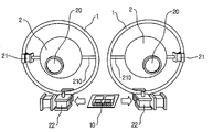
- FIG. 1 is a front view showing an object to which an exemplary embodiment of a system for stabilization control is applied.
- the system for stabilization control is used for controlling position and direction of an object having a first body (not shown) and a second body 2 , connected to each other.
- the first body corresponds to a head portion of a mobile robot
- the second body 2 corresponds to an eye portion connected to the head portion.
- the second body 2 is connected to the first body via a circular connector 1 , but it is just an example. In other exemplary embodiments, the second body 2 may be directly connected to the first body or connected to the first body via a differently shaped member. In case the mobile robot makes a movement or rotation, the head portion of the mobile robot (i.e. the first body) is moved, so the second body 2 connected to the first body is moved or rotated along with the mobile robot.
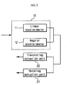
- FIG. 2 is a block diagram showing an exemplary embodiment of a system for stabilization control.
- the system for stabilization control includes an artificial vestibular apparatus 10 , a translating actuation unit 22 and a rotating actuation unit 21 .
- the artificial vestibular apparatus 10 detects a signal corresponding to movement or rotation of the head portion of the artificial robot, which is the first body.
- the artificial vestibular apparatus 10 may include a linear accelerometer 11 for detecting movement of the first body and an angular accelerometer 12 for detecting rotation of the first body.
- the linear accelerometer 11 detects linear acceleration caused by movement of the first body in at least one axial direction.
- the linear accelerometer 11 may be configured as a three-axial linear accelerometer which detects linear accelerations in three axial directions.
- the linear accelerometer 11 may include one or more linear accelerometers which detect linear accelerations in different axial directions.
- the angular accelerometer 12 detects angular acceleration caused by rotation of the first body with respect to at least one axial direction.
- the angular accelerometer 12 may be configured as a three-axial angular accelerometer which detects angular acceleration with respect to three axial directions.
- the angular accelerometer 12 may include one or more angular accelerometers which detect angular accelerations in different axial directions.
- the artificial vestibular apparatus 10 detects a movement signal corresponding to movement of the first body and a rotation signal corresponding to rotation of the first body using the linear accelerometer 11 and the angular accelerometer 12 .
- the detected signals are respectively transmitted to the translating actuation unit 22 and the rotating actuation unit 21 for the control of the second body 2 .
- the translating actuation unit 22 feeds the movement signal of the first body, transmitted from the artificial vestibular apparatus 10 , back to the second body 2 to control position of the second body 2 .
- the translating actuation unit 22 moves the second body 2 in a direction which decreases the effect caused by the movement of the first body, e.g., in a direction opposite to the moving direction of the first body.
- the translating actuation unit 22 may be configured to move the second body in an arbitrary direction in space including forward/backward, right/left and upward/downward directions. Due to negative feedback of the translating actuation unit 22 , the position of the second body 2 may be constantly maintained without being influenced by movement or vibration of the first body.
- the translating actuation unit 22 is connected to a connector 1 which connects the second body 2 to the first body. That is, the translating actuation unit 22 is configured to control the position of the second body 2 indirectly. However, it is just an example, and the translating actuation unit 22 may be directly connected to the second body 2 or configured to control position of the second body 2 using differently shaped devices.
- the rotating actuation unit 21 feeds the rotation signal of the first body, transmitted from the artificial vestibular apparatus 10 , back to the second body 2 to control rotation of the second body 2 .
- the rotating actuation unit 21 rotates the second body 2 in a direction which decreases the effect caused by the rotation of the first body, e.g., in a direction opposite to the rotating direction of the first body.
- the rotating actuation unit 21 may include a rotary shaft 210 connected to the second body 2 so as to perform the aforementioned negative feedback.
- the direction of the second body 2 may be constantly maintained without being influenced by the rotation of the first body.
- the rotating actuation unit 21 includes one rotary shaft 210 , but it is just an example.
- the rotating actuation unit 21 may control a direction of the second body 2 using a plurality of rotary shafts.
- the second body 2 includes a device 20 for receiving image information from the outside.
- the second body 2 corresponds to an eyeball portion of a mobile robot, and it includes a device corresponding to an eye of the mobile robot, which receives image information from the outside.
- the second body 2 may have improved stability, and it is possible to prevent any blurring from occurring at the received image information.
- the second body 2 corresponds to an eyeball portion of a mobile robot, but it is just an example. In other embodiments, the second body 2 may be any other part of an object. Also, any portion having a function other than receiving image information may be set as the second body 2 when the system for stabilization control is applied.
- FIG. 3 is a flowchart illustrating an exemplary embodiment of a method for stabilization control.
- the method for stabilization control starts from a process S 1 for the artificial vestibular apparatus 10 to detect a movement signal generated by movement of the first body and a process S 2 for the artificial vestibular apparatus 10 to detect a rotation signal generated by rotation of the first body.
- the movement signal and the rotation signal of the first body, detected by the artificial vestibular apparatus 10 are transmitted to the translating actuation unit 22 and the rotating actuation unit 21 , respectively. Then, the translating actuation unit 22 controls position of the second body connected to the first body in response to the transmitted movement signal (S 3 ), and the rotating actuation unit 21 controls rotation of the second body in response to the transmitted rotation signal (S 4 ).
- the translating actuation unit 22 may be configured to move the second body in a direction opposite to a moving direction of the first body
- the rotating actuation unit 21 may be configured to move the second body in a direction opposite to a rotating direction of the first body.
- the position and direction of the second body may be constantly maintained without being influenced by movement or rotation of the first body.
- a specific portion of the object may maintain its position and direction constantly by means of an artificial vestibular apparatus which mimics VOR.
- the system and method for stabilization control are applied to a vision system of a mobile robot, the vision system may be controlled to obtain stabile image information even when the mobile robot is moving. As a result, it is possible to prevent any blurring from occurring at the image information received by the mobile robot.
Abstract
Description
- This application claims priority to Korean Patent Application No. 10-2008-106002, filed on Oct. 28, 2008, and all the benefits accruing therefrom under 35 U.S.C. §119, the contents of which in its entirety are herein incorporated by reference.
- 1. Field
- Exemplary embodiments relate to a system and a method for stabilization control adopting vestibulo-ocular reflex (VOR), and more particularly to a system and a method for stabilization control, which generate a signal corresponding to movement or rotation of a moving object such as a mobile robot using an artificial vestibular apparatus reproducing VOR of a living body, and stably control a predetermined portion of the object in response to the generated signal.
- 2. Description of the Related Art
- Mobile robots are widely used for various works such as unmanned guard replacing humans. For such a mobile robot to accomplish a work, the robot should have a driving unit which allows the robot to move or rotate. Also, a vision system for obtaining image signals from outside is one of the essential functions of the mobile robot such that the mobile robot may recognize or trace a specific object.
- However, since the driving unit and the vision system are connected to the same body, a target to be recognized by the vision system may deviate from an input range of the vision system if the driving unit makes a rotation or a portion where the vision system is positioned is rotated. In addition, even when a target does not deviate, blurring may occur in the image signal obtained by the vision system, which deteriorates an object recognition rate and accuracy of the vision system.
- According to exemplary embodiments, there are provided a system and a method for stabilization control, which may maintain position and direction of a specific portion of a moving object, such as a mobile robot, even if the mobile robot is vibrated or rotated.
- According to an exemplary embodiment, there is provided a system for stabilization control, which controls position and direction of an object having first and second bodies connected to each other, the system including an artificial vestibular apparatus for outputting a movement signal corresponding to movement of the first body and a rotation signal corresponding to rotation of the first body; a translating actuation unit connected between the first and second bodies and controlling position of the second body in response to the movement signal; and a rotating actuation unit connected between the first and second bodies and controlling rotation of the second body in response to the rotation signal.
- According to another exemplary embodiment, there is provided a method for stabilization control, which controls position and direction of an object having first and second bodies connected to each other, the method including outputting a movement signal corresponding to movement of the first body and a rotation signal corresponding to rotation of the first body; controlling position of the second body in response to the movement signal; and controlling rotation of the second body in response to the rotation signal.
- Using the system and method for stabilization control, when a moving object such as an artificial robot is vibrated or rotated, a specific portion of the object may maintain its position and direction constantly. If the system and method for stabilization control are applied to a vision system of a mobile robot, the vision system may obtain stabile image information even when the mobile robot is moving, thereby preventing any blurring from occurring at the image information.
- The above and other aspects, features and advantages of the disclosed exemplary embodiments will be more apparent from the following detailed description taken in conjunction with the accompanying drawings in which:
-
FIG. 1 shows an object to which an exemplary embodiment of a system for stabilization control is applied; -
FIG. 2 is a block diagram showing an exemplary embodiment of a system for stabilization control; and -
FIG. 3 is a flowchart illustrating an exemplary embodiment of a method for stabilization control. - Exemplary embodiments now will be described more fully hereinafter with reference to the accompanying drawings, in which exemplary embodiments are shown. This disclosure may, however, be embodied in many different forms and should not be construed as limited to the exemplary embodiments set forth therein. Rather, these exemplary embodiments are provided so that this disclosure will be thorough and complete, and will fully convey the scope of this disclosure to those skilled in the art. In the description, details of well-known features and techniques may be omitted to avoid unnecessarily obscuring the presented embodiments.
- The terminology used herein is for the purpose of describing particular embodiments only and is not intended to be limiting of this disclosure. As used herein, the singular forms “a”, “an” and “the” are intended to include the plural forms as well, unless the context clearly indicates otherwise. Furthermore, the use of the terms a, an, etc. does not denote a limitation of quantity, but rather denotes the presence of at least one of the referenced item. The use of the terms “first”, “second”, and the like does not imply any particular order, but they are included to identify individual elements. Moreover, the use of the terms first, second, etc. does not denote any order or importance, but rather the terms first, second, etc. are used to distinguish one element from another. It will be further understood that the terms “comprises” and/or “comprising”, or “includes” and/or “including” when used in this specification, specify the presence of stated features, regions, integers, steps, operations, elements, and/or components, but do not preclude the presence or addition of one or more other features, regions, integers, steps, operations, elements, components, and/or groups thereof.
- Unless otherwise defined, all terms (including technical and scientific terms) used herein have the same meaning as commonly understood by one of ordinary skill in the art. It will be further understood that terms, such as those defined in commonly used dictionaries, should be interpreted as having a meaning that is consistent with their meaning in the context of the relevant art and the present disclosure, and will not be interpreted in an idealized or overly formal sense unless expressly so defined herein.
- In the drawings, like reference numerals in the drawings denote like elements. The shape, size and regions, and the like, of the drawing may be exaggerated for clarity.
- Exemplary embodiment of a system and a method for stabilization control may control a moving object such as a mobile robot by adopting vestibulo-ocular reflex (VOR) such that a specific portion of the object may maintain its position and direction constantly even when the entire object is vibrated or rotated.
- The VOR is one of the visual operations essential to a living body. The VOR is a reflex eye movement which stabilizes images of an object while the living body is moving. The VOR maintains the images from outside on the retina as long as possible during head movement by producing an eye movement in the direction opposite to head movement.
- Exemplary embodiments of a system and a method for stabilization control may apply VOR to mobile robots such that a specific portion of the mobile robot is moved in a direction opposite to a moving direction in which the mobile robot is entirely or partially moved. For example, the system and method for stabilization control may control a vision system to which visual information is input to the mobile robot such that the visual information received by the mobile robot may be stabilized.
- Hereinafter, exemplary embodiments of the system and method for stabilization control are explained in detail with reference to the accompanying drawings.
-
FIG. 1 is a front view showing an object to which an exemplary embodiment of a system for stabilization control is applied. - Referring to
FIG. 1 , the system for stabilization control is used for controlling position and direction of an object having a first body (not shown) and asecond body 2, connected to each other. InFIG. 1 , the first body corresponds to a head portion of a mobile robot, and thesecond body 2 corresponds to an eye portion connected to the head portion. - In
FIG. 1 , thesecond body 2 is connected to the first body via a circular connector 1, but it is just an example. In other exemplary embodiments, thesecond body 2 may be directly connected to the first body or connected to the first body via a differently shaped member. In case the mobile robot makes a movement or rotation, the head portion of the mobile robot (i.e. the first body) is moved, so thesecond body 2 connected to the first body is moved or rotated along with the mobile robot. -
FIG. 2 is a block diagram showing an exemplary embodiment of a system for stabilization control. - Referring to
FIGS. 1 and 2 , the system for stabilization control includes an artificialvestibular apparatus 10, a translatingactuation unit 22 and a rotatingactuation unit 21. - The
artificial vestibular apparatus 10 detects a signal corresponding to movement or rotation of the head portion of the artificial robot, which is the first body. In an exemplary embodiment, theartificial vestibular apparatus 10 may include alinear accelerometer 11 for detecting movement of the first body and anangular accelerometer 12 for detecting rotation of the first body. - The
linear accelerometer 11 detects linear acceleration caused by movement of the first body in at least one axial direction. In an exemplary embodiment, thelinear accelerometer 11 may be configured as a three-axial linear accelerometer which detects linear accelerations in three axial directions. Alternatively, in another exemplary embodiment, thelinear accelerometer 11 may include one or more linear accelerometers which detect linear accelerations in different axial directions. - Meanwhile, the
angular accelerometer 12 detects angular acceleration caused by rotation of the first body with respect to at least one axial direction. In an exemplary embodiment, theangular accelerometer 12 may be configured as a three-axial angular accelerometer which detects angular acceleration with respect to three axial directions. Alternatively, in another exemplary embodiment, theangular accelerometer 12 may include one or more angular accelerometers which detect angular accelerations in different axial directions. - The
artificial vestibular apparatus 10 detects a movement signal corresponding to movement of the first body and a rotation signal corresponding to rotation of the first body using thelinear accelerometer 11 and theangular accelerometer 12. The detected signals are respectively transmitted to the translatingactuation unit 22 and the rotatingactuation unit 21 for the control of thesecond body 2. - The translating
actuation unit 22 feeds the movement signal of the first body, transmitted from the artificialvestibular apparatus 10, back to thesecond body 2 to control position of thesecond body 2. In other words, if a signal indicating that the first body is moved in a specific direction is transmitted to the translatingactuation unit 22, the translatingactuation unit 22 moves thesecond body 2 in a direction which decreases the effect caused by the movement of the first body, e.g., in a direction opposite to the moving direction of the first body. - The translating
actuation unit 22 may be configured to move the second body in an arbitrary direction in space including forward/backward, right/left and upward/downward directions. Due to negative feedback of the translatingactuation unit 22, the position of thesecond body 2 may be constantly maintained without being influenced by movement or vibration of the first body. - In
FIG. 1 , the translatingactuation unit 22 is connected to a connector 1 which connects thesecond body 2 to the first body. That is, the translatingactuation unit 22 is configured to control the position of thesecond body 2 indirectly. However, it is just an example, and the translatingactuation unit 22 may be directly connected to thesecond body 2 or configured to control position of thesecond body 2 using differently shaped devices. - Meanwhile, the rotating
actuation unit 21 feeds the rotation signal of the first body, transmitted from the artificialvestibular apparatus 10, back to thesecond body 2 to control rotation of thesecond body 2. In other words, if a signal indicating that the first body is rotated in a specific direction is transmitted to therotating actuation unit 21, the rotatingactuation unit 21 rotates thesecond body 2 in a direction which decreases the effect caused by the rotation of the first body, e.g., in a direction opposite to the rotating direction of the first body. - Referring to
FIG. 1 , the rotatingactuation unit 21 may include arotary shaft 210 connected to thesecond body 2 so as to perform the aforementioned negative feedback. By rotating thesecond body 2 in a direction opposite to a rotating direction of the first body using therotary shaft 210, the direction of thesecond body 2 may be constantly maintained without being influenced by the rotation of the first body. - In
FIG. 1 , the rotatingactuation unit 21 includes onerotary shaft 210, but it is just an example. Therotating actuation unit 21 may control a direction of thesecond body 2 using a plurality of rotary shafts. - Also, in
FIG. 1 , thesecond body 2 includes adevice 20 for receiving image information from the outside. In an exemplary embodiment, thesecond body 2 corresponds to an eyeball portion of a mobile robot, and it includes a device corresponding to an eye of the mobile robot, which receives image information from the outside. - In this case, if position and direction of the
second body 2 are controlled using the system for stabilization control, even when the first body (i.e. a head portion of a mobile robot) is moved, thesecond body 2 constantly maintains its position and direction. Thus, the image information received by thesecond body 2 may have improved stability, and it is possible to prevent any blurring from occurring at the received image information. - In
FIG. 1 , thesecond body 2 corresponds to an eyeball portion of a mobile robot, but it is just an example. In other embodiments, thesecond body 2 may be any other part of an object. Also, any portion having a function other than receiving image information may be set as thesecond body 2 when the system for stabilization control is applied. -
FIG. 3 is a flowchart illustrating an exemplary embodiment of a method for stabilization control. - For the convenience, the method for stabilization control is explained with reference to
FIGS. 2 and 3 . The method for stabilization control starts from a process S1 for the artificialvestibular apparatus 10 to detect a movement signal generated by movement of the first body and a process S2 for the artificialvestibular apparatus 10 to detect a rotation signal generated by rotation of the first body. - The movement signal and the rotation signal of the first body, detected by the artificial
vestibular apparatus 10, are transmitted to the translatingactuation unit 22 and therotating actuation unit 21, respectively. Then, the translatingactuation unit 22 controls position of the second body connected to the first body in response to the transmitted movement signal (S3), and therotating actuation unit 21 controls rotation of the second body in response to the transmitted rotation signal (S4). - For example, in an exemplary embodiment, the translating
actuation unit 22 may be configured to move the second body in a direction opposite to a moving direction of the first body, and therotating actuation unit 21 may be configured to move the second body in a direction opposite to a rotating direction of the first body. In this case, the position and direction of the second body may be constantly maintained without being influenced by movement or rotation of the first body. - Using the system and method for stabilization control, while an object such as a mobile robot is moved due to vibration, rotation or the like, a specific portion of the object may maintain its position and direction constantly by means of an artificial vestibular apparatus which mimics VOR.
- Also, if the system and method for stabilization control are applied to a vision system of a mobile robot, the vision system may be controlled to obtain stabile image information even when the mobile robot is moving. As a result, it is possible to prevent any blurring from occurring at the image information received by the mobile robot.
- While the exemplary embodiments have been shown and described, it will be understood by those skilled in the art that various changes in form and details may be made thereto without departing from the spirit and scope of this disclosure as defined by the appended claims.
- In addition, many modifications can be made to adapt a particular situation or material to the teachings of this disclosure without departing from the essential scope thereof. Therefore, it is intended that this disclosure not be limited to the particular exemplary embodiments disclosed as the best mode contemplated for carrying out this disclosure, but that this disclosure will include all embodiments falling within the scope of the appended claims.
Claims (7)
Applications Claiming Priority (3)
| Application Number | Priority Date | Filing Date | Title |
|---|---|---|---|
| KR20070108986 | 2007-10-29 | ||
| KR10-2008-0106002 | 2008-10-28 | ||
| KR1020080106002A KR101059806B1 (en) | 2007-10-29 | 2008-10-28 | Stabilization Control System and Method Applying Vestibular Reflection |
Publications (2)
| Publication Number | Publication Date |
|---|---|
| US20100106295A1 true US20100106295A1 (en) | 2010-04-29 |
| US8285416B2 US8285416B2 (en) | 2012-10-09 |
Family
ID=40854278
Family Applications (1)
| Application Number | Title | Priority Date | Filing Date |
|---|---|---|---|
| US12/370,077 Active 2030-10-18 US8285416B2 (en) | 2007-10-29 | 2009-02-12 | System and method for stabilization control adopting vestibulo-ocular reflex |
Country Status (2)
| Country | Link |
|---|---|
| US (1) | US8285416B2 (en) |
| KR (1) | KR101059806B1 (en) |
Cited By (6)
| Publication number | Priority date | Publication date | Assignee | Title |
|---|---|---|---|---|
| CN105472373A (en) * | 2015-11-18 | 2016-04-06 | 中国兵器工业计算机应用技术研究所 | Bionic electronic image stabilizing method based on vestibular reflection mechanism and device |
| US20160151917A1 (en) * | 2013-03-15 | 2016-06-02 | JIBO, Inc. | Multi-segment social robot |
| US9714145B1 (en) * | 2012-07-20 | 2017-07-25 | Amazon Technologies, Inc. | Container stacking configurations |
| US9926131B1 (en) | 2012-07-20 | 2018-03-27 | Amazon Technologies, Inc. | Custom container stacking configurations |
| US10118723B2 (en) | 2012-03-23 | 2018-11-06 | Amazon Technologies, Inc. | Custom containers in a materials handling facility |
| US20220198959A1 (en) * | 2019-03-22 | 2022-06-23 | Essilor International | Device for simulating a physiological behaviour of a mammal using a virtual mammal, process and computer program |
Families Citing this family (12)
| Publication number | Priority date | Publication date | Assignee | Title |
|---|---|---|---|---|
| KR101251184B1 (en) | 2010-08-05 | 2013-04-08 | 서울대학교산학협력단 | Vision tracking system and method using motion commands |
| US10602927B2 (en) | 2013-01-25 | 2020-03-31 | Wesley W. O. Krueger | Ocular-performance-based head impact measurement using a faceguard |
| US10716469B2 (en) | 2013-01-25 | 2020-07-21 | Wesley W. O. Krueger | Ocular-performance-based head impact measurement applied to rotationally-centered impact mitigation systems and methods |
| US10231614B2 (en) | 2014-07-08 | 2019-03-19 | Wesley W. O. Krueger | Systems and methods for using virtual reality, augmented reality, and/or a synthetic 3-dimensional information for the measurement of human ocular performance |
| US11389059B2 (en) | 2013-01-25 | 2022-07-19 | Wesley W. O. Krueger | Ocular-performance-based head impact measurement using a faceguard |
| US9370302B2 (en) | 2014-07-08 | 2016-06-21 | Wesley W. O. Krueger | System and method for the measurement of vestibulo-ocular reflex to improve human performance in an occupational environment |
| US11490809B2 (en) | 2013-01-25 | 2022-11-08 | Wesley W. O. Krueger | Ocular parameter-based head impact measurement using a face shield |
| US11504051B2 (en) | 2013-01-25 | 2022-11-22 | Wesley W. O. Krueger | Systems and methods for observing eye and head information to measure ocular parameters and determine human health status |
| US9788714B2 (en) | 2014-07-08 | 2017-10-17 | Iarmourholdings, Inc. | Systems and methods using virtual reality or augmented reality environments for the measurement and/or improvement of human vestibulo-ocular performance |
| US20150081345A1 (en) * | 2013-09-17 | 2015-03-19 | Darwin & Davinci, Unltd., Llc | Asset collective redirection leverage multiplier platform apparatuses, methods and sysytems |
| JP7401197B2 (en) * | 2019-05-29 | 2023-12-19 | キヤノン株式会社 | Imaging device |
| US11376733B2 (en) * | 2019-06-11 | 2022-07-05 | Facebook Technologies, Llc | Mechanical eyeball for animatronic devices |
Citations (5)
| Publication number | Priority date | Publication date | Assignee | Title |
|---|---|---|---|---|
| US4818858A (en) * | 1984-10-25 | 1989-04-04 | Canon Kabushiki Kaisha | Visual sensor system for producing stereoscopic visual information |
| US5984475A (en) * | 1997-12-05 | 1999-11-16 | Mcgill University | Stereoscopic gaze controller |
| US6507359B1 (en) * | 1993-09-20 | 2003-01-14 | Canon Kabushiki Kaisha | Image display system |
| US20040190863A1 (en) * | 1993-12-28 | 2004-09-30 | Hiroshi Nishimura | Image recording unit and camera |
| US20050185945A1 (en) * | 2002-10-22 | 2005-08-25 | Xiaolin Zhang | Bionic automatic vision and line of sight control system and method |
Family Cites Families (2)
| Publication number | Priority date | Publication date | Assignee | Title |
|---|---|---|---|---|
| JP2002049067A (en) | 2000-08-03 | 2002-02-15 | Canon Inc | Vibration preventing device |
| WO2002031945A2 (en) | 2000-10-13 | 2002-04-18 | Clarity, Llc | Magnetic actuation and positioning |
-
2008
- 2008-10-28 KR KR1020080106002A patent/KR101059806B1/en active IP Right Grant
-
2009
- 2009-02-12 US US12/370,077 patent/US8285416B2/en active Active
Patent Citations (5)
| Publication number | Priority date | Publication date | Assignee | Title |
|---|---|---|---|---|
| US4818858A (en) * | 1984-10-25 | 1989-04-04 | Canon Kabushiki Kaisha | Visual sensor system for producing stereoscopic visual information |
| US6507359B1 (en) * | 1993-09-20 | 2003-01-14 | Canon Kabushiki Kaisha | Image display system |
| US20040190863A1 (en) * | 1993-12-28 | 2004-09-30 | Hiroshi Nishimura | Image recording unit and camera |
| US5984475A (en) * | 1997-12-05 | 1999-11-16 | Mcgill University | Stereoscopic gaze controller |
| US20050185945A1 (en) * | 2002-10-22 | 2005-08-25 | Xiaolin Zhang | Bionic automatic vision and line of sight control system and method |
Cited By (9)
| Publication number | Priority date | Publication date | Assignee | Title |
|---|---|---|---|---|
| US10118723B2 (en) | 2012-03-23 | 2018-11-06 | Amazon Technologies, Inc. | Custom containers in a materials handling facility |
| US9714145B1 (en) * | 2012-07-20 | 2017-07-25 | Amazon Technologies, Inc. | Container stacking configurations |
| US9926131B1 (en) | 2012-07-20 | 2018-03-27 | Amazon Technologies, Inc. | Custom container stacking configurations |
| US9969571B1 (en) | 2012-07-20 | 2018-05-15 | Amazon Technologies, Inc. | Container stacking configurations |
| US10246275B1 (en) | 2012-07-20 | 2019-04-02 | Amazon Technologies, Inc. | Container stacking configurations |
| US20160151917A1 (en) * | 2013-03-15 | 2016-06-02 | JIBO, Inc. | Multi-segment social robot |
| US10357881B2 (en) * | 2013-03-15 | 2019-07-23 | Sqn Venture Income Fund, L.P. | Multi-segment social robot |
| CN105472373A (en) * | 2015-11-18 | 2016-04-06 | 中国兵器工业计算机应用技术研究所 | Bionic electronic image stabilizing method based on vestibular reflection mechanism and device |
| US20220198959A1 (en) * | 2019-03-22 | 2022-06-23 | Essilor International | Device for simulating a physiological behaviour of a mammal using a virtual mammal, process and computer program |
Also Published As
| Publication number | Publication date |
|---|---|
| US8285416B2 (en) | 2012-10-09 |
| KR101059806B1 (en) | 2011-08-26 |
| KR20090043461A (en) | 2009-05-06 |
Similar Documents
| Publication | Publication Date | Title |
|---|---|---|
| US8285416B2 (en) | System and method for stabilization control adopting vestibulo-ocular reflex | |
| JP4899217B2 (en) | Eye movement control device using the principle of vestibulo-oculomotor reflex | |
| US8233786B2 (en) | Image shake correction apparatus and image pickup apparatus | |
| WO2018191963A1 (en) | Remote control, camera mount, and camera mount control method, device, and system | |
| CN104914864B (en) | A kind of mobile device, mobile device control system and control method | |
| US20180154523A1 (en) | Apparatus and method of controlling robot arm | |
| US10379627B2 (en) | Handheld device and positioning method thereof | |
| US20190132514A1 (en) | Image capturing apparatus, supporting apparatus, and control methods therefor | |
| CN110869283A (en) | Control method and device of cloud deck, cloud deck system and unmanned aerial vehicle | |
| JP6026695B1 (en) | Control device, moving body, control method, and program | |
| EP3822732B1 (en) | Control method and apparatus for unmanned aerial vehicle and unmanned aerial vehicle | |
| JP6318455B1 (en) | Control device, imaging device, moving object, control method, and program | |
| JP2019084898A (en) | Flight body maneuvering system and method for maneuvering flight body using flight body maneuvering system | |
| KR101019336B1 (en) | System and method for stabilization contol using an inertial sensor | |
| KR102121287B1 (en) | Camera system and controlling method of Camera system | |
| CN109302546B (en) | Camera assembly and electronic equipment | |
| WO2017030694A1 (en) | Camera zoom based on sensor data | |
| US11372316B2 (en) | Lens barrel, camera body, camera system | |
| JP6331180B1 (en) | Control device, imaging device, imaging system, flying object, control method, and program | |
| US20120057035A1 (en) | Force compensation systems and methods | |
| US20230026930A1 (en) | Image processing apparatus, system, image processing method, and image processing program | |
| JP2017207650A (en) | Lens device | |
| JP2020173262A (en) | Correction device, method for correction, and program for correction device | |
| CN108885101B (en) | Control method, processing device, processor, aircraft and somatosensory system | |
| KR20160099883A (en) | Optical image stabilizer and camera module including the same |
Legal Events
| Date | Code | Title | Description |
|---|---|---|---|
| AS | Assignment |
Owner name: SNU R&DB FOUNDATION,KOREA, REPUBLIC OF Free format text: ASSIGNMENT OF ASSIGNORS INTEREST;ASSIGNORS:CHO, DONG-IL;KO, HYOUNGHO;PARK, JAEHONG;AND OTHERS;REEL/FRAME:022250/0803 Effective date: 20090209 Owner name: SNU R&DB FOUNDATION, KOREA, REPUBLIC OF Free format text: ASSIGNMENT OF ASSIGNORS INTEREST;ASSIGNORS:CHO, DONG-IL;KO, HYOUNGHO;PARK, JAEHONG;AND OTHERS;REEL/FRAME:022250/0803 Effective date: 20090209 |
|
| STCF | Information on status: patent grant |
Free format text: PATENTED CASE |
|
| FEPP | Fee payment procedure |
Free format text: PAT HOLDER CLAIMS SMALL ENTITY STATUS, ENTITY STATUS SET TO SMALL (ORIGINAL EVENT CODE: LTOS); ENTITY STATUS OF PATENT OWNER: SMALL ENTITY |
|
| FPAY | Fee payment |
Year of fee payment: 4 |
|
| FEPP | Fee payment procedure |
Free format text: PAYOR NUMBER ASSIGNED (ORIGINAL EVENT CODE: ASPN); ENTITY STATUS OF PATENT OWNER: SMALL ENTITY |
|
| MAFP | Maintenance fee payment |
Free format text: PAYMENT OF MAINTENANCE FEE, 8TH YR, SMALL ENTITY (ORIGINAL EVENT CODE: M2552); ENTITY STATUS OF PATENT OWNER: SMALL ENTITY Year of fee payment: 8 |
|
| MAFP | Maintenance fee payment |
Free format text: PAYMENT OF MAINTENANCE FEE, 12TH YR, SMALL ENTITY (ORIGINAL EVENT CODE: M2553); ENTITY STATUS OF PATENT OWNER: SMALL ENTITY Year of fee payment: 12 |