US20100190332A1 - Method of Forming a Copper Topped Interconnect Structure that has Thin and Thick Copper Traces - Google Patents
Method of Forming a Copper Topped Interconnect Structure that has Thin and Thick Copper Traces Download PDFInfo
- Publication number
- US20100190332A1 US20100190332A1 US12/751,894 US75189410A US2010190332A1 US 20100190332 A1 US20100190332 A1 US 20100190332A1 US 75189410 A US75189410 A US 75189410A US 2010190332 A1 US2010190332 A1 US 2010190332A1
- Authority
- US
- United States
- Prior art keywords
- structures
- copper
- forming
- plated
- sealed
- Prior art date
- Legal status (The legal status is an assumption and is not a legal conclusion. Google has not performed a legal analysis and makes no representation as to the accuracy of the status listed.)
- Granted
Links
Images


Classifications
-
- H—ELECTRICITY
- H01—ELECTRIC ELEMENTS
- H01L—SEMICONDUCTOR DEVICES NOT COVERED BY CLASS H10
- H01L21/00—Processes or apparatus adapted for the manufacture or treatment of semiconductor or solid state devices or of parts thereof
- H01L21/70—Manufacture or treatment of devices consisting of a plurality of solid state components formed in or on a common substrate or of parts thereof; Manufacture of integrated circuit devices or of parts thereof
- H01L21/71—Manufacture of specific parts of devices defined in group H01L21/70
- H01L21/768—Applying interconnections to be used for carrying current between separate components within a device comprising conductors and dielectrics
- H01L21/76838—Applying interconnections to be used for carrying current between separate components within a device comprising conductors and dielectrics characterised by the formation and the after-treatment of the conductors
- H01L21/76885—By forming conductive members before deposition of protective insulating material, e.g. pillars, studs
-
- H—ELECTRICITY
- H01—ELECTRIC ELEMENTS
- H01L—SEMICONDUCTOR DEVICES NOT COVERED BY CLASS H10
- H01L21/00—Processes or apparatus adapted for the manufacture or treatment of semiconductor or solid state devices or of parts thereof
- H01L21/70—Manufacture or treatment of devices consisting of a plurality of solid state components formed in or on a common substrate or of parts thereof; Manufacture of integrated circuit devices or of parts thereof
- H01L21/71—Manufacture of specific parts of devices defined in group H01L21/70
- H01L21/768—Applying interconnections to be used for carrying current between separate components within a device comprising conductors and dielectrics
- H01L21/76838—Applying interconnections to be used for carrying current between separate components within a device comprising conductors and dielectrics characterised by the formation and the after-treatment of the conductors
- H01L21/76841—Barrier, adhesion or liner layers
- H01L21/7685—Barrier, adhesion or liner layers the layer covering a conductive structure
- H01L21/76852—Barrier, adhesion or liner layers the layer covering a conductive structure the layer also covering the sidewalls of the conductive structure
-
- H—ELECTRICITY
- H01—ELECTRIC ELEMENTS
- H01L—SEMICONDUCTOR DEVICES NOT COVERED BY CLASS H10
- H01L23/00—Details of semiconductor or other solid state devices
- H01L23/52—Arrangements for conducting electric current within the device in operation from one component to another, i.e. interconnections, e.g. wires, lead frames
- H01L23/522—Arrangements for conducting electric current within the device in operation from one component to another, i.e. interconnections, e.g. wires, lead frames including external interconnections consisting of a multilayer structure of conductive and insulating layers inseparably formed on the semiconductor body
- H01L23/528—Geometry or layout of the interconnection structure
- H01L23/5283—Cross-sectional geometry
-
- H—ELECTRICITY
- H01—ELECTRIC ELEMENTS
- H01L—SEMICONDUCTOR DEVICES NOT COVERED BY CLASS H10
- H01L23/00—Details of semiconductor or other solid state devices
- H01L23/52—Arrangements for conducting electric current within the device in operation from one component to another, i.e. interconnections, e.g. wires, lead frames
- H01L23/522—Arrangements for conducting electric current within the device in operation from one component to another, i.e. interconnections, e.g. wires, lead frames including external interconnections consisting of a multilayer structure of conductive and insulating layers inseparably formed on the semiconductor body
- H01L23/532—Arrangements for conducting electric current within the device in operation from one component to another, i.e. interconnections, e.g. wires, lead frames including external interconnections consisting of a multilayer structure of conductive and insulating layers inseparably formed on the semiconductor body characterised by the materials
- H01L23/53204—Conductive materials
- H01L23/53209—Conductive materials based on metals, e.g. alloys, metal silicides
- H01L23/53228—Conductive materials based on metals, e.g. alloys, metal silicides the principal metal being copper
- H01L23/53238—Additional layers associated with copper layers, e.g. adhesion, barrier, cladding layers
-
- H—ELECTRICITY
- H01—ELECTRIC ELEMENTS
- H01L—SEMICONDUCTOR DEVICES NOT COVERED BY CLASS H10
- H01L24/00—Arrangements for connecting or disconnecting semiconductor or solid-state bodies; Methods or apparatus related thereto
- H01L24/01—Means for bonding being attached to, or being formed on, the surface to be connected, e.g. chip-to-package, die-attach, "first-level" interconnects; Manufacturing methods related thereto
- H01L24/02—Bonding areas ; Manufacturing methods related thereto
- H01L24/04—Structure, shape, material or disposition of the bonding areas prior to the connecting process
- H01L24/06—Structure, shape, material or disposition of the bonding areas prior to the connecting process of a plurality of bonding areas
-
- H—ELECTRICITY
- H01—ELECTRIC ELEMENTS
- H01L—SEMICONDUCTOR DEVICES NOT COVERED BY CLASS H10
- H01L24/00—Arrangements for connecting or disconnecting semiconductor or solid-state bodies; Methods or apparatus related thereto
- H01L24/01—Means for bonding being attached to, or being formed on, the surface to be connected, e.g. chip-to-package, die-attach, "first-level" interconnects; Manufacturing methods related thereto
- H01L24/10—Bump connectors ; Manufacturing methods related thereto
- H01L24/12—Structure, shape, material or disposition of the bump connectors prior to the connecting process
- H01L24/14—Structure, shape, material or disposition of the bump connectors prior to the connecting process of a plurality of bump connectors
-
- H—ELECTRICITY
- H01—ELECTRIC ELEMENTS
- H01L—SEMICONDUCTOR DEVICES NOT COVERED BY CLASS H10
- H01L2224/00—Indexing scheme for arrangements for connecting or disconnecting semiconductor or solid-state bodies and methods related thereto as covered by H01L24/00
- H01L2224/01—Means for bonding being attached to, or being formed on, the surface to be connected, e.g. chip-to-package, die-attach, "first-level" interconnects; Manufacturing methods related thereto
- H01L2224/02—Bonding areas; Manufacturing methods related thereto
- H01L2224/04—Structure, shape, material or disposition of the bonding areas prior to the connecting process
- H01L2224/0401—Bonding areas specifically adapted for bump connectors, e.g. under bump metallisation [UBM]
-
- H—ELECTRICITY
- H01—ELECTRIC ELEMENTS
- H01L—SEMICONDUCTOR DEVICES NOT COVERED BY CLASS H10
- H01L2224/00—Indexing scheme for arrangements for connecting or disconnecting semiconductor or solid-state bodies and methods related thereto as covered by H01L24/00
- H01L2224/01—Means for bonding being attached to, or being formed on, the surface to be connected, e.g. chip-to-package, die-attach, "first-level" interconnects; Manufacturing methods related thereto
- H01L2224/02—Bonding areas; Manufacturing methods related thereto
- H01L2224/04—Structure, shape, material or disposition of the bonding areas prior to the connecting process
- H01L2224/04042—Bonding areas specifically adapted for wire connectors, e.g. wirebond pads
-
- H—ELECTRICITY
- H01—ELECTRIC ELEMENTS
- H01L—SEMICONDUCTOR DEVICES NOT COVERED BY CLASS H10
- H01L2224/00—Indexing scheme for arrangements for connecting or disconnecting semiconductor or solid-state bodies and methods related thereto as covered by H01L24/00
- H01L2224/01—Means for bonding being attached to, or being formed on, the surface to be connected, e.g. chip-to-package, die-attach, "first-level" interconnects; Manufacturing methods related thereto
- H01L2224/02—Bonding areas; Manufacturing methods related thereto
- H01L2224/04—Structure, shape, material or disposition of the bonding areas prior to the connecting process
- H01L2224/05—Structure, shape, material or disposition of the bonding areas prior to the connecting process of an individual bonding area
- H01L2224/05001—Internal layers
- H01L2224/0502—Disposition
- H01L2224/05022—Disposition the internal layer being at least partially embedded in the surface
-
- H—ELECTRICITY
- H01—ELECTRIC ELEMENTS
- H01L—SEMICONDUCTOR DEVICES NOT COVERED BY CLASS H10
- H01L2224/00—Indexing scheme for arrangements for connecting or disconnecting semiconductor or solid-state bodies and methods related thereto as covered by H01L24/00
- H01L2224/01—Means for bonding being attached to, or being formed on, the surface to be connected, e.g. chip-to-package, die-attach, "first-level" interconnects; Manufacturing methods related thereto
- H01L2224/02—Bonding areas; Manufacturing methods related thereto
- H01L2224/04—Structure, shape, material or disposition of the bonding areas prior to the connecting process
- H01L2224/05—Structure, shape, material or disposition of the bonding areas prior to the connecting process of an individual bonding area
- H01L2224/05001—Internal layers
- H01L2224/0502—Disposition
- H01L2224/05026—Disposition the internal layer being disposed in a recess of the surface
- H01L2224/05027—Disposition the internal layer being disposed in a recess of the surface the internal layer extending out of an opening
-
- H—ELECTRICITY
- H01—ELECTRIC ELEMENTS
- H01L—SEMICONDUCTOR DEVICES NOT COVERED BY CLASS H10
- H01L2224/00—Indexing scheme for arrangements for connecting or disconnecting semiconductor or solid-state bodies and methods related thereto as covered by H01L24/00
- H01L2224/01—Means for bonding being attached to, or being formed on, the surface to be connected, e.g. chip-to-package, die-attach, "first-level" interconnects; Manufacturing methods related thereto
- H01L2224/02—Bonding areas; Manufacturing methods related thereto
- H01L2224/04—Structure, shape, material or disposition of the bonding areas prior to the connecting process
- H01L2224/05—Structure, shape, material or disposition of the bonding areas prior to the connecting process of an individual bonding area
- H01L2224/05001—Internal layers
- H01L2224/05099—Material
- H01L2224/051—Material with a principal constituent of the material being a metal or a metalloid, e.g. boron [B], silicon [Si], germanium [Ge], arsenic [As], antimony [Sb], tellurium [Te] and polonium [Po], and alloys thereof
- H01L2224/05117—Material with a principal constituent of the material being a metal or a metalloid, e.g. boron [B], silicon [Si], germanium [Ge], arsenic [As], antimony [Sb], tellurium [Te] and polonium [Po], and alloys thereof the principal constituent melting at a temperature of greater than or equal to 400°C and less than 950°C
- H01L2224/05124—Aluminium [Al] as principal constituent
-
- H—ELECTRICITY
- H01—ELECTRIC ELEMENTS
- H01L—SEMICONDUCTOR DEVICES NOT COVERED BY CLASS H10
- H01L2224/00—Indexing scheme for arrangements for connecting or disconnecting semiconductor or solid-state bodies and methods related thereto as covered by H01L24/00
- H01L2224/01—Means for bonding being attached to, or being formed on, the surface to be connected, e.g. chip-to-package, die-attach, "first-level" interconnects; Manufacturing methods related thereto
- H01L2224/02—Bonding areas; Manufacturing methods related thereto
- H01L2224/04—Structure, shape, material or disposition of the bonding areas prior to the connecting process
- H01L2224/05—Structure, shape, material or disposition of the bonding areas prior to the connecting process of an individual bonding area
- H01L2224/05001—Internal layers
- H01L2224/05099—Material
- H01L2224/051—Material with a principal constituent of the material being a metal or a metalloid, e.g. boron [B], silicon [Si], germanium [Ge], arsenic [As], antimony [Sb], tellurium [Te] and polonium [Po], and alloys thereof
- H01L2224/05138—Material with a principal constituent of the material being a metal or a metalloid, e.g. boron [B], silicon [Si], germanium [Ge], arsenic [As], antimony [Sb], tellurium [Te] and polonium [Po], and alloys thereof the principal constituent melting at a temperature of greater than or equal to 950°C and less than 1550°C
- H01L2224/05147—Copper [Cu] as principal constituent
-
- H—ELECTRICITY
- H01—ELECTRIC ELEMENTS
- H01L—SEMICONDUCTOR DEVICES NOT COVERED BY CLASS H10
- H01L2224/00—Indexing scheme for arrangements for connecting or disconnecting semiconductor or solid-state bodies and methods related thereto as covered by H01L24/00
- H01L2224/01—Means for bonding being attached to, or being formed on, the surface to be connected, e.g. chip-to-package, die-attach, "first-level" interconnects; Manufacturing methods related thereto
- H01L2224/02—Bonding areas; Manufacturing methods related thereto
- H01L2224/04—Structure, shape, material or disposition of the bonding areas prior to the connecting process
- H01L2224/05—Structure, shape, material or disposition of the bonding areas prior to the connecting process of an individual bonding area
- H01L2224/05001—Internal layers
- H01L2224/05099—Material
- H01L2224/051—Material with a principal constituent of the material being a metal or a metalloid, e.g. boron [B], silicon [Si], germanium [Ge], arsenic [As], antimony [Sb], tellurium [Te] and polonium [Po], and alloys thereof
- H01L2224/05163—Material with a principal constituent of the material being a metal or a metalloid, e.g. boron [B], silicon [Si], germanium [Ge], arsenic [As], antimony [Sb], tellurium [Te] and polonium [Po], and alloys thereof the principal constituent melting at a temperature of greater than 1550°C
- H01L2224/05166—Titanium [Ti] as principal constituent
-
- H—ELECTRICITY
- H01—ELECTRIC ELEMENTS
- H01L—SEMICONDUCTOR DEVICES NOT COVERED BY CLASS H10
- H01L2224/00—Indexing scheme for arrangements for connecting or disconnecting semiconductor or solid-state bodies and methods related thereto as covered by H01L24/00
- H01L2224/01—Means for bonding being attached to, or being formed on, the surface to be connected, e.g. chip-to-package, die-attach, "first-level" interconnects; Manufacturing methods related thereto
- H01L2224/02—Bonding areas; Manufacturing methods related thereto
- H01L2224/04—Structure, shape, material or disposition of the bonding areas prior to the connecting process
- H01L2224/05—Structure, shape, material or disposition of the bonding areas prior to the connecting process of an individual bonding area
- H01L2224/0554—External layer
- H01L2224/0556—Disposition
- H01L2224/05568—Disposition the whole external layer protruding from the surface
-
- H—ELECTRICITY
- H01—ELECTRIC ELEMENTS
- H01L—SEMICONDUCTOR DEVICES NOT COVERED BY CLASS H10
- H01L2224/00—Indexing scheme for arrangements for connecting or disconnecting semiconductor or solid-state bodies and methods related thereto as covered by H01L24/00
- H01L2224/01—Means for bonding being attached to, or being formed on, the surface to be connected, e.g. chip-to-package, die-attach, "first-level" interconnects; Manufacturing methods related thereto
- H01L2224/02—Bonding areas; Manufacturing methods related thereto
- H01L2224/04—Structure, shape, material or disposition of the bonding areas prior to the connecting process
- H01L2224/05—Structure, shape, material or disposition of the bonding areas prior to the connecting process of an individual bonding area
- H01L2224/0554—External layer
- H01L2224/0556—Disposition
- H01L2224/0557—Disposition the external layer being disposed on a via connection of the semiconductor or solid-state body
-
- H—ELECTRICITY
- H01—ELECTRIC ELEMENTS
- H01L—SEMICONDUCTOR DEVICES NOT COVERED BY CLASS H10
- H01L2224/00—Indexing scheme for arrangements for connecting or disconnecting semiconductor or solid-state bodies and methods related thereto as covered by H01L24/00
- H01L2224/01—Means for bonding being attached to, or being formed on, the surface to be connected, e.g. chip-to-package, die-attach, "first-level" interconnects; Manufacturing methods related thereto
- H01L2224/02—Bonding areas; Manufacturing methods related thereto
- H01L2224/04—Structure, shape, material or disposition of the bonding areas prior to the connecting process
- H01L2224/05—Structure, shape, material or disposition of the bonding areas prior to the connecting process of an individual bonding area
- H01L2224/0554—External layer
- H01L2224/0556—Disposition
- H01L2224/05571—Disposition the external layer being disposed in a recess of the surface
-
- H—ELECTRICITY
- H01—ELECTRIC ELEMENTS
- H01L—SEMICONDUCTOR DEVICES NOT COVERED BY CLASS H10
- H01L2224/00—Indexing scheme for arrangements for connecting or disconnecting semiconductor or solid-state bodies and methods related thereto as covered by H01L24/00
- H01L2224/01—Means for bonding being attached to, or being formed on, the surface to be connected, e.g. chip-to-package, die-attach, "first-level" interconnects; Manufacturing methods related thereto
- H01L2224/02—Bonding areas; Manufacturing methods related thereto
- H01L2224/04—Structure, shape, material or disposition of the bonding areas prior to the connecting process
- H01L2224/05—Structure, shape, material or disposition of the bonding areas prior to the connecting process of an individual bonding area
- H01L2224/0554—External layer
- H01L2224/05599—Material
- H01L2224/056—Material with a principal constituent of the material being a metal or a metalloid, e.g. boron [B], silicon [Si], germanium [Ge], arsenic [As], antimony [Sb], tellurium [Te] and polonium [Po], and alloys thereof
- H01L2224/05638—Material with a principal constituent of the material being a metal or a metalloid, e.g. boron [B], silicon [Si], germanium [Ge], arsenic [As], antimony [Sb], tellurium [Te] and polonium [Po], and alloys thereof the principal constituent melting at a temperature of greater than or equal to 950°C and less than 1550°C
- H01L2224/05647—Copper [Cu] as principal constituent
-
- H—ELECTRICITY
- H01—ELECTRIC ELEMENTS
- H01L—SEMICONDUCTOR DEVICES NOT COVERED BY CLASS H10
- H01L2224/00—Indexing scheme for arrangements for connecting or disconnecting semiconductor or solid-state bodies and methods related thereto as covered by H01L24/00
- H01L2224/01—Means for bonding being attached to, or being formed on, the surface to be connected, e.g. chip-to-package, die-attach, "first-level" interconnects; Manufacturing methods related thereto
- H01L2224/02—Bonding areas; Manufacturing methods related thereto
- H01L2224/04—Structure, shape, material or disposition of the bonding areas prior to the connecting process
- H01L2224/06—Structure, shape, material or disposition of the bonding areas prior to the connecting process of a plurality of bonding areas
- H01L2224/0601—Structure
- H01L2224/0603—Bonding areas having different sizes, e.g. different heights or widths
-
- H—ELECTRICITY
- H01—ELECTRIC ELEMENTS
- H01L—SEMICONDUCTOR DEVICES NOT COVERED BY CLASS H10
- H01L2224/00—Indexing scheme for arrangements for connecting or disconnecting semiconductor or solid-state bodies and methods related thereto as covered by H01L24/00
- H01L2224/01—Means for bonding being attached to, or being formed on, the surface to be connected, e.g. chip-to-package, die-attach, "first-level" interconnects; Manufacturing methods related thereto
- H01L2224/02—Bonding areas; Manufacturing methods related thereto
- H01L2224/04—Structure, shape, material or disposition of the bonding areas prior to the connecting process
- H01L2224/06—Structure, shape, material or disposition of the bonding areas prior to the connecting process of a plurality of bonding areas
- H01L2224/061—Disposition
- H01L2224/06102—Disposition the bonding areas being at different heights
-
- H—ELECTRICITY
- H01—ELECTRIC ELEMENTS
- H01L—SEMICONDUCTOR DEVICES NOT COVERED BY CLASS H10
- H01L2224/00—Indexing scheme for arrangements for connecting or disconnecting semiconductor or solid-state bodies and methods related thereto as covered by H01L24/00
- H01L2224/01—Means for bonding being attached to, or being formed on, the surface to be connected, e.g. chip-to-package, die-attach, "first-level" interconnects; Manufacturing methods related thereto
- H01L2224/10—Bump connectors; Manufacturing methods related thereto
- H01L2224/12—Structure, shape, material or disposition of the bump connectors prior to the connecting process
- H01L2224/14—Structure, shape, material or disposition of the bump connectors prior to the connecting process of a plurality of bump connectors
- H01L2224/1401—Structure
- H01L2224/1403—Bump connectors having different sizes, e.g. different diameters, heights or widths
-
- H—ELECTRICITY
- H01—ELECTRIC ELEMENTS
- H01L—SEMICONDUCTOR DEVICES NOT COVERED BY CLASS H10
- H01L24/00—Arrangements for connecting or disconnecting semiconductor or solid-state bodies; Methods or apparatus related thereto
- H01L24/01—Means for bonding being attached to, or being formed on, the surface to be connected, e.g. chip-to-package, die-attach, "first-level" interconnects; Manufacturing methods related thereto
- H01L24/02—Bonding areas ; Manufacturing methods related thereto
- H01L24/03—Manufacturing methods
-
- H—ELECTRICITY
- H01—ELECTRIC ELEMENTS
- H01L—SEMICONDUCTOR DEVICES NOT COVERED BY CLASS H10
- H01L24/00—Arrangements for connecting or disconnecting semiconductor or solid-state bodies; Methods or apparatus related thereto
- H01L24/01—Means for bonding being attached to, or being formed on, the surface to be connected, e.g. chip-to-package, die-attach, "first-level" interconnects; Manufacturing methods related thereto
- H01L24/02—Bonding areas ; Manufacturing methods related thereto
- H01L24/04—Structure, shape, material or disposition of the bonding areas prior to the connecting process
- H01L24/05—Structure, shape, material or disposition of the bonding areas prior to the connecting process of an individual bonding area
Definitions
- the present invention relates to an interconnect structure and, more particularly, to a copper-topped interconnect structure that has thin and thick copper traces, and a method of forming the copper-topped interconnect structure.
- a metal interconnect structure is a multi-layered structure that electrically interconnects together the various devices formed on a semiconductor wafer to realize an electrical circuit.
- the top layer of the interconnect structure is commonly formed from copper.
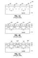
- FIGS. 1A-1E show a series of cross-sectional views that illustrate a prior-art method 100 of forming a copper-topped interconnect structure.
- method 100 utilizes a conventionally-formed semiconductor wafer 110 that has an interconnect structure which includes a non-conductive region and a number of conductive structures 112 , such as aluminum traces, that touch and sit on the non-conductive region.
- conductive structures 112 such as aluminum traces
- method 100 begins by depositing a layer of passivation material 114 on the non-conductive region and the conductive structures 112 .
- Method 100 continues by forming and patterning a mask 116 on passivation layer 114 .
- the exposed regions of passivation layer 114 are etched to form a number of openings 120 .
- Some of the openings 120 in turn, expose the conductive structures 112 .
- Mask 116 is then removed.
- seed layer 122 is formed on the conductive structures 112 and passivation layer 114 .
- Seed layer 122 typically includes a layer of titanium (e.g., 300 ⁇ thick) and an overlying layer of copper (e.g., 3000 ⁇ thick).
- the titanium layer enhances the adhesion between the underlying aluminum traces 112 and the overlying layer of copper.
- Seed layer 122 can also include an overlying layer of titanium, which is stripped before plating.
- seed layer 122 can further include a conductive barrier layer that lies between the aluminum traces 112 and the lower titanium layer.)
- a plating mold 124 is formed on seed layer 122 to have a number of openings 126 that expose the number of openings 120 .
- plating mold 124 copper is electroplated to form a number of copper traces 130 in plating mold 124 .
- the copper traces 130 which are electrically connected to the conductive structures 112 , are separated from each other by a substantially uniform minimum distance MD.
- each copper trace 130 has a top surface 130 T and a thickness of approximately 5 ⁇ m.
- a layer of non-conductive material e.g., benzocyclobutene (BCB) or a polymer
- BCB benzocyclobutene
- a mask 134 is formed on non-conductive layer 132 .
- the exposed regions of non-conductive layer 132 are etched to form openings 136 that expose the copper traces 130 .
- Mask 134 is then removed.
- a metal layer 138 is formed on non-conductive layer 132 to fill up the openings 134 and contact the copper traces 130 .
- Metal layer 138 can be implemented with, for example, gold or aluminum with an underlying titanium layer. The titanium layer enhances the adhesion of the aluminum to the copper.
- a mask 140 is formed and patterned on metal layer 138 .
- the exposed regions of metal layer 138 are etched to form a number of metal bond pads 142 over selected regions of the top surfaces of the copper traces 130 .
- Mask 140 is then removed. After mask 140 has been removed, solder balls can be attached to the metal bond pads 142 or, alternately, bonding wires can be attached to the metal bond pads 142 .
- method 100 provides an approach to forming a copper-topped interconnect structure, there is a need for additional methods of forming copper-topped interconnect structures.
- FIGS. 1A-1E are a series of cross-sectional views taken along a common straight cut plane illustrating a prior art method 100 of forming a copper-topped interconnect structure.
- FIGS. 2A-2I are a series of cross-sectional views taken along a common straight cut plane illustrating a method 200 of forming a copper-topped interconnect structure in accordance with the present invention.
- FIGS. 2A-2I show a series of cross-sectional views that illustrate a method 200 of forming a copper-topped interconnect structure in accordance with the present invention.
- the present invention allows the combination of high density design areas, which do not require high current metal traces, with low density design areas, which require high current metal traces.
- the present invention allows thin and narrow metal traces to be combined with thick and wide metal traces on the same chip.
- method 200 utilizes a conventionally-formed semiconductor wafer 210 that has an interconnect structure which includes a non-conductive region and a number of conductive structures 212 , such as aluminum traces, that touch and sit on the non-conductive region.
- the conductive structures 212 include a number of first conductive structures 212 - 1 and a number of second conductive structures 212 - 2 that are to carry substantially more current than the first conductive structures 212 - 1 .
- method 200 begins by depositing a layer of passivation material 216 on the non-conductive region and the conductive structures 212 .
- Method 200 continues by forming and patterning a mask 218 on passivation layer 216 .
- the exposed regions of passivation layer 216 are etched to form a number of openings 220 .
- the openings 220 include a number of first openings 220 - 1 that are each separated from an adjacent first opening 220 - 1 by a first minimum distance MD 1 .
- the first openings 220 - 1 expose the first conductive structures 212 - 1 .
- the openings 220 also include a number of second openings 220 - 2 that are each separated from an adjacent second opening 220 - 2 by a minimum distance MD 2 .
- the second openings 220 - 2 expose the second conductive structures 212 - 2 .
- the first and second openings 220 - 1 and 220 - 2 in turn, have cross-sectional widths 220 - 1 W and 220 - 2 W, respectively.
- the cross-sectional widths 220 - 2 W can be larger than the cross-sectional widths 220 - 1 W as needed to carry a larger current.
- Mask 218 is then removed.
- seed layer 222 is formed on the conductive structures 212 and passivation layer 216 .
- Seed layer 222 typically includes a layer of titanium (e.g., 300 ⁇ thick) and an overlying layer of copper (e.g., 3000 ⁇ thick).
- the titanium layer enhances the adhesion between the underlying aluminum traces 212 and the overlying layer of copper.
- Seed layer 222 can also include an overlying layer of titanium (Ti—Cu—Ti), which is stripped before plating.
- seed layer 222 can also include a conductive barrier layer that lies between the aluminum traces 212 and the lower titanium layer.
- a plating mold 224 is formed on seed layer 222 to have a number of openings 226 that expose the number of first openings 220 - 1 .
- Each opening 226 has a cross-sectional width 226 W.
- the cross-sectional width 226 W which is substantially greater than the cross-sectional width 220 - 1 W, is measured along the same straight cut plane as the cross-sectional width 220 - 1 W.
- plating mold 224 covers and protects the second openings 220 - 2 and the portion of seed layer 222 that is formed in the second openings 220 - 2 .
- first copper traces 230 are electroplated to form a number of first copper traces 230 in plating mold 224 .
- the electroplated first copper traces 230 are substantially only copper.
- the first copper traces 230 some of which are electrically connected to the first conductive structures 212 - 1 , are each separated from an adjacent first copper trace 230 by a minimum distance MD 11 .
- each first copper trace 230 has a cross-sectional width 230 W, a top surface 230 T, and a thickness of, for example, 5 ⁇ m.
- the cross-sectional width 230 W of a first copper trace 230 is measured normal to a length of the first copper trace 230 and normal to a thickness of the first copper trace 230 .
- a plating mold 232 is formed on seed layer 222 and the first copper traces 230 to have a number of openings 234 that expose the number of second openings 220 - 2 .
- Plating mold 232 is substantially thicker than plating mold 224 .
- Each opening 234 has a cross-sectional width 234 W.
- the cross-sectional width 234 W which is substantially greater than the cross-sectional width 220 - 2 W, is measured along the same straight cut plane as the cross-section width 220 - 2 W.
- plating mold 232 covers and protects the first copper traces 230 .
- the cross-sectional widths 234 W of the openings 234 in plating mold 232 which are measured along the same straight cut plane as the cross-sectional widths 226 W, are substantially larger than the cross-sectional widths 226 W of the openings 226 in plating mold 224 .
- plating mold 232 copper is electroplated to form a number of second copper traces 236 in plating mold 232 .
- the electroplated second copper traces 236 are substantially only copper.
- the second copper traces 236 some of which are electrically connected to the second conductive structures 212 - 2 , are each separated from an adjacent second copper trace 236 by a minimum distance MD 21 .
- each second copper trace 236 has a cross-sectional width 236 W, a top surface 236 T, and a thickness of, for example, 15 ⁇ m.
- the cross-sectional width 236 W of a second copper trace 236 is measured normal to a length of the second copper trace 236 and normal to a thickness of the second copper trace 236 .
- the minimum cross-sectional widths of the portions of the second copper traces 236 that lie completely above passivation layer 216 are substantially greater than the minimum cross-sectional widths of the portions of the first copper traces 230 that lie completely above passivation layer 216 .
- the cross-sectional width 236 W which is substantially greater than the cross-section width 230 W, is measured along the same straight cut plane as the cross-section width 230 W.
- the minimum distance MD 21 which is measured along the same straight cut plane as minimum distance MD 11 , is substantially greater than minimum distance MD 11 .
- a conductive barrier layer 240 can be optionally deposited over passivation layer 216 , the first copper traces 230 , and the second copper traces 236 .
- Barrier layer 240 which can be implemented with, for example, aluminum-copper, cobalt, nickel, and/or gold, allow non-copper wire bonding lines or non-copper solder balls to be attached to the copper traces 230 and 236 , and can also provide resistance to humidity and corrosion.
- barrier layer 240 has been formed, a mask 242 is then formed and patterned on barrier layer 240 .
- the exposed regions of barrier layer 240 are removed from the top surface of passivation layer 216 to form a number of sealed first copper traces 244 and a number of sealed second copper traces 246 .
- Mask 242 is then removed.
- the copper traces 230 have top surfaces that all lie substantially in a first common plane CP 1
- the copper traces 236 have top surfaces that all lie substantially in a second common plane CP 2 that lies substantially above the first common plane CP 1 .
- solder balls 248 can be attached to selected regions on the copper traces 230 and 236 as illustrated in FIG. 2G , or thin bonding wires 250 can be attached to the copper traces 230 and 236 as alternately illustrated in FIG. 2G . Solder balls 248 or bonding wires 250 can alternately be connected to the copper traces 230 and 236 if barrier layer 240 is not used.
- plating mold 232 can be removed without removing the underlying regions of seed layer 222 , followed by the deposition of barrier layer 240 over seed layer 222 , the first copper traces 230 , and the second copper traces 236 .
- Mask 242 is then formed as above. After this, as shown in FIG. 21 , the exposed regions of barrier layer 240 and the underlying seed layer 222 are removed from the top surface of passivation layer 216 to form the first and second sealed copper traces 244 and 246 .
- Mask 242 is then removed.
- a method of forming a copper-topped metal interconnect structure has been described.
- One of the advantages of the present invention is that a chip can be implemented with both high density design areas which do not require high current metal traces, and low density design areas which require high current metal traces.
- traces with low current requirements can be implemented with copper traces 230 that require a relatively small minimum distance, such as 5 ⁇ m
- traces with high current requirements can be implemented with copper traces 236 that require a relatively large minimum distance, such as 15 ⁇ m.
- the present invention When compared to prior art copper structures which only utilize traces with a small minimum distance between adjacent traces, the present invention substantially reduces the resistance of the high current traces. When compared to prior art copper structures which only utilize traces with a large minimum distance between traces, the present invention allows more low current traces to be formed in the same physical space, thereby increasing the routing density.
Abstract
A copper-topped interconnect structure allows the combination of high density design areas, which have low current requirements that can be met with tightly packed thin and narrow copper traces, and low density design areas, which have high current requirements that can be met with more widely spaced thick and wide copper traces, on the same chip.
Description
- This is a divisional application of application Ser. No. 12/283,852 filed on Sep. 15, 2008 by Abdalla Aly Naem et al.
- 1. Field of the Invention
- The present invention relates to an interconnect structure and, more particularly, to a copper-topped interconnect structure that has thin and thick copper traces, and a method of forming the copper-topped interconnect structure.
- 2. Description of the Related Art
- A metal interconnect structure is a multi-layered structure that electrically interconnects together the various devices formed on a semiconductor wafer to realize an electrical circuit. In order to lower the resistance of the interconnect structure, the top layer of the interconnect structure is commonly formed from copper.
-
FIGS. 1A-1E show a series of cross-sectional views that illustrate a prior-art method 100 of forming a copper-topped interconnect structure. As shown inFIG. 1A ,method 100 utilizes a conventionally-formedsemiconductor wafer 110 that has an interconnect structure which includes a non-conductive region and a number ofconductive structures 112, such as aluminum traces, that touch and sit on the non-conductive region. - As further shown in
FIG. 1A ,method 100 begins by depositing a layer ofpassivation material 114 on the non-conductive region and theconductive structures 112.Method 100 continues by forming and patterning amask 116 onpassivation layer 114. Following this, the exposed regions ofpassivation layer 114 are etched to form a number ofopenings 120. Some of theopenings 120, in turn, expose theconductive structures 112.Mask 116 is then removed. - As shown in
FIG. 1B , aftermask 116 has been removed, aseed layer 122 is formed on theconductive structures 112 andpassivation layer 114.Seed layer 122 typically includes a layer of titanium (e.g., 300 Å thick) and an overlying layer of copper (e.g., 3000 Å thick). The titanium layer enhances the adhesion between the underlying aluminum traces 112 and the overlying layer of copper. (Seed layer 122 can also include an overlying layer of titanium, which is stripped before plating. In addition,seed layer 122 can further include a conductive barrier layer that lies between thealuminum traces 112 and the lower titanium layer.) Next, afterseed layer 122 has been formed, a platingmold 124 is formed onseed layer 122 to have a number ofopenings 126 that expose the number ofopenings 120. - As shown in
FIG. 1C , following the formation of platingmold 124, copper is electroplated to form a number ofcopper traces 130 in platingmold 124. Thecopper traces 130, which are electrically connected to theconductive structures 112, are separated from each other by a substantially uniform minimum distance MD. In addition, eachcopper trace 130 has atop surface 130T and a thickness of approximately 5 μm. After the electroplating process has been completed, platingmold 124 and theseed layer 122 that underlies platingmold 124 are then removed. - Next, as shown in
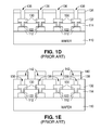
FIG. 1D , a layer of non-conductive material (e.g., benzocyclobutene (BCB) or a polymer) 132 is deposited onpassivation layer 114 and thecopper traces 130. Afternon-conductive layer 132 has been deposited, amask 134 is formed onnon-conductive layer 132. Following this, the exposed regions ofnon-conductive layer 132 are etched to formopenings 136 that expose thecopper traces 130.Mask 134 is then removed. - As shown in
FIG. 1E , after theopenings 136 innon-conductive layer 132 have been formed, ametal layer 138 is formed onnon-conductive layer 132 to fill up theopenings 134 and contact thecopper traces 130.Metal layer 138 can be implemented with, for example, gold or aluminum with an underlying titanium layer. The titanium layer enhances the adhesion of the aluminum to the copper. - After this, a
mask 140 is formed and patterned onmetal layer 138. Next, the exposed regions ofmetal layer 138 are etched to form a number ofmetal bond pads 142 over selected regions of the top surfaces of thecopper traces 130.Mask 140 is then removed. Aftermask 140 has been removed, solder balls can be attached to themetal bond pads 142 or, alternately, bonding wires can be attached to themetal bond pads 142. - Although
method 100 provides an approach to forming a copper-topped interconnect structure, there is a need for additional methods of forming copper-topped interconnect structures. -
FIGS. 1A-1E are a series of cross-sectional views taken along a common straight cut plane illustrating aprior art method 100 of forming a copper-topped interconnect structure. -
FIGS. 2A-2I are a series of cross-sectional views taken along a common straight cut plane illustrating amethod 200 of forming a copper-topped interconnect structure in accordance with the present invention. -
FIGS. 2A-2I show a series of cross-sectional views that illustrate amethod 200 of forming a copper-topped interconnect structure in accordance with the present invention. As described in greater detail below, the present invention allows the combination of high density design areas, which do not require high current metal traces, with low density design areas, which require high current metal traces. As a result, the present invention allows thin and narrow metal traces to be combined with thick and wide metal traces on the same chip. - As shown in
FIG. 2A ,method 200 utilizes a conventionally-formedsemiconductor wafer 210 that has an interconnect structure which includes a non-conductive region and a number ofconductive structures 212, such as aluminum traces, that touch and sit on the non-conductive region. Theconductive structures 212, in turn, include a number of first conductive structures 212-1 and a number of second conductive structures 212-2 that are to carry substantially more current than the first conductive structures 212-1. - As further shown in
FIG. 2A ,method 200 begins by depositing a layer ofpassivation material 216 on the non-conductive region and theconductive structures 212.Method 200 continues by forming and patterning amask 218 onpassivation layer 216. Following this, the exposed regions ofpassivation layer 216 are etched to form a number ofopenings 220. - The
openings 220 include a number of first openings 220-1 that are each separated from an adjacent first opening 220-1 by a first minimum distance MD1. In addition, as shown inFIG. 2A , the first openings 220-1 expose the first conductive structures 212-1. Theopenings 220 also include a number of second openings 220-2 that are each separated from an adjacent second opening 220-2 by a minimum distance MD2. In addition, as further shown inFIG. 2A , the second openings 220-2 expose the second conductive structures 212-2. The first and second openings 220-1 and 220-2, in turn, have cross-sectional widths 220-1W and 220-2W, respectively. The cross-sectional widths 220-2W can be larger than the cross-sectional widths 220-1W as needed to carry a larger current.Mask 218 is then removed. - As shown in
FIG. 2B , aftermask 218 has been removed, aseed layer 222 is formed on theconductive structures 212 andpassivation layer 216.Seed layer 222 typically includes a layer of titanium (e.g., 300 Å thick) and an overlying layer of copper (e.g., 3000 Å thick). The titanium layer enhances the adhesion between the underlying aluminum traces 212 and the overlying layer of copper. (Seed layer 222 can also include an overlying layer of titanium (Ti—Cu—Ti), which is stripped before plating. In addition,seed layer 222 can also include a conductive barrier layer that lies between the aluminum traces 212 and the lower titanium layer.) - Next, a
plating mold 224 is formed onseed layer 222 to have a number ofopenings 226 that expose the number of first openings 220-1. Eachopening 226, in turn, has across-sectional width 226W. Thecross-sectional width 226W, which is substantially greater than the cross-sectional width 220-1W, is measured along the same straight cut plane as the cross-sectional width 220-1W. In accordance with the present invention, as further shown inFIG. 2B , platingmold 224 covers and protects the second openings 220-2 and the portion ofseed layer 222 that is formed in the second openings 220-2. - As shown in
FIG. 2C , following the formation of platingmold 224, copper is electroplated to form a number of first copper traces 230 in platingmold 224. Although trace materials may be present, the electroplated first copper traces 230 are substantially only copper. The first copper traces 230, some of which are electrically connected to the first conductive structures 212-1, are each separated from an adjacentfirst copper trace 230 by a minimum distance MD11. - In addition, each
first copper trace 230 has across-sectional width 230W, atop surface 230T, and a thickness of, for example, 5 μm. Thecross-sectional width 230W of afirst copper trace 230 is measured normal to a length of thefirst copper trace 230 and normal to a thickness of thefirst copper trace 230. After the electroplating process has been completed, platingmold 224 is removed. - Next, as shown in
FIG. 2D , following the removal of platingmold 224, aplating mold 232 is formed onseed layer 222 and the first copper traces 230 to have a number ofopenings 234 that expose the number of second openings 220-2. Platingmold 232, in turn, is substantially thicker than platingmold 224. - Each
opening 234 has across-sectional width 234W. Thecross-sectional width 234W, which is substantially greater than the cross-sectional width 220-2W, is measured along the same straight cut plane as the cross-section width 220-2W. In accordance with the present invention, as further shown inFIG. 2D , platingmold 232 covers and protects the first copper traces 230. In addition, thecross-sectional widths 234W of theopenings 234 in platingmold 232, which are measured along the same straight cut plane as thecross-sectional widths 226W, are substantially larger than thecross-sectional widths 226W of theopenings 226 in platingmold 224. - As shown in
FIG. 2E , following the formation of platingmold 232, copper is electroplated to form a number of second copper traces 236 in platingmold 232. Although trace materials may be present, the electroplated second copper traces 236 are substantially only copper. The second copper traces 236, some of which are electrically connected to the second conductive structures 212-2, are each separated from an adjacentsecond copper trace 236 by a minimum distance MD21. - In addition, each
second copper trace 236 has across-sectional width 236W, atop surface 236T, and a thickness of, for example, 15 μm. Thecross-sectional width 236W of asecond copper trace 236 is measured normal to a length of thesecond copper trace 236 and normal to a thickness of thesecond copper trace 236. The minimum cross-sectional widths of the portions of the second copper traces 236 that lie completely abovepassivation layer 216 are substantially greater than the minimum cross-sectional widths of the portions of the first copper traces 230 that lie completely abovepassivation layer 216. - Further, as further shown in
FIG. 2E , thecross-sectional width 236W, which is substantially greater than thecross-section width 230W, is measured along the same straight cut plane as thecross-section width 230W. Further, the minimum distance MD21, which is measured along the same straight cut plane as minimum distance MD11, is substantially greater than minimum distance MD11. After the electroplating process has been completed, platingmold 232 and the underlying regions ofseed layer 222 are removed. - As shown in
FIG. 2F , after platingmold 232 and the underlying regions ofseed layer 222 have been removed, aconductive barrier layer 240 can be optionally deposited overpassivation layer 216, the first copper traces 230, and the second copper traces 236.Barrier layer 240, which can be implemented with, for example, aluminum-copper, cobalt, nickel, and/or gold, allow non-copper wire bonding lines or non-copper solder balls to be attached to the copper traces 230 and 236, and can also provide resistance to humidity and corrosion. - Following this, after
barrier layer 240 has been formed, amask 242 is then formed and patterned onbarrier layer 240. Next, as shown inFIG. 2G , the exposed regions ofbarrier layer 240 are removed from the top surface ofpassivation layer 216 to form a number of sealed first copper traces 244 and a number of sealed second copper traces 246.Mask 242 is then removed. Thus, as shown inFIG. 2G , the copper traces 230 have top surfaces that all lie substantially in a first common plane CP1, while the copper traces 236 have top surfaces that all lie substantially in a second common plane CP2 that lies substantially above the first common plane CP1. - After
mask 242 has been removed,solder balls 248 can be attached to selected regions on the copper traces 230 and 236 as illustrated inFIG. 2G , orthin bonding wires 250 can be attached to the copper traces 230 and 236 as alternately illustrated inFIG. 2G .Solder balls 248 orbonding wires 250 can alternately be connected to the copper traces 230 and 236 ifbarrier layer 240 is not used. - Alternately, as shown in
FIG. 2H , platingmold 232 can be removed without removing the underlying regions ofseed layer 222, followed by the deposition ofbarrier layer 240 overseed layer 222, the first copper traces 230, and the second copper traces 236.Mask 242 is then formed as above. After this, as shown inFIG. 21 , the exposed regions ofbarrier layer 240 and theunderlying seed layer 222 are removed from the top surface ofpassivation layer 216 to form the first and second sealed copper traces 244 and 246.Mask 242 is then removed. - Thus, a method of forming a copper-topped metal interconnect structure has been described. One of the advantages of the present invention is that a chip can be implemented with both high density design areas which do not require high current metal traces, and low density design areas which require high current metal traces. For example, traces with low current requirements can be implemented with copper traces 230 that require a relatively small minimum distance, such as 5 μm, while traces with high current requirements can be implemented with copper traces 236 that require a relatively large minimum distance, such as 15 μm.
- When compared to prior art copper structures which only utilize traces with a small minimum distance between adjacent traces, the present invention substantially reduces the resistance of the high current traces. When compared to prior art copper structures which only utilize traces with a large minimum distance between traces, the present invention allows more low current traces to be formed in the same physical space, thereby increasing the routing density.
- It should be understood that the above descriptions are examples of the present invention, and that various alternatives of the invention described herein may be employed in practicing the invention. Thus, it is intended that the following claims define the scope of the invention and that structures and methods within the scope of these claims and their equivalents be covered thereby.
Claims (16)
1. A method of forming a semiconductor structure comprising:
forming an isolation structure that touches a plurality of first metal structures and a plurality of second metal structures;
simultaneously forming a plurality of first isolation openings and a plurality of second isolation openings in the isolation structure, the plurality of first isolation openings exposing the plurality of first metal structures, the plurality of second isolation openings exposing the plurality of second metal structures;
forming a seed layer that touches the isolation structure, the plurality of first metal structures, and the plurality of second metal structures; and
forming a first plating mold that touches the seed layer, the first plating mold having a plurality of first mold openings that expose the seed layer that lies directly over the plurality of first metal structures, the first plating mold covering the seed layer that lies directly over the plurality of second metal structures.
2. The method of claim 1 wherein an adjacent pair of first metal structures are spaced apart by a first minimum distance, an adjacent pair of second metal structures are spaced apart by a second minimum distance, the second minimum distance being greater than the first minimum distance.
3. The method of claim 1 and further comprising forming a plurality of first plated structures in the plurality of first mold openings in the first plating mold.
4. The method of claim 3 wherein the plurality of first plated structures are substantially only copper.
5. The method of claim 3 and further comprising:
removing the first plating mold; and
forming a second plating mold that touches the seed layer, the second plating mold having a plurality of second mold openings that expose the seed layer that lies directly over the plurality of second metal structures, the second plating mold covering the plurality of first plated structures.
6. The method of claim 5 wherein the second plating mold is thicker than the first plating mold.
7. The method of claim 5 and further comprising forming a plurality of second plated structures in the plurality of second mold openings in the second plating mold.
8. The method of claim 7 wherein the plurality of second plated structures are substantially only copper.
9. The method of claim 7 wherein a portion of a first plated structure that lies above the isolation structure has a first minimum width, a portion of a second plated structure that lies above the isolation structure has a second minimum width, the second minimum width being greater than the first minimum width.
10. The method of claim 7 wherein a thickness of each of the plurality of second plated structures is greater than a thickness of each of the plurality of first plated structures.
11. The method of claim 7 and further comprising removing the second plating mold to expose a region of the seed layer that lies directly below the second plating mold.
12. The method of claim 11 and further comprising:
removing the region of the seed layer; and
forming a sealant layer that touches the isolation structure, the plurality of first plated structures, and the plurality of second plated structures.
13. The method of claim 12 and further comprising:
removing the sealant layer from a portion of the isolation structure to form a plurality of first sealed plated structures and a plurality of second sealed plated structures; and
forming a plurality of solder balls that touch the plurality of first sealed plated structures and the plurality of second sealed plated structures.
14. The method of claim 12 and further comprising:
removing the sealant layer from a portion of the isolation structure to form a plurality of first sealed plated structures and a plurality of second sealed plated structures; and
forming a plurality of bonding wires that touch the plurality of first sealed plated structures and the plurality of second sealed plated structures.
15. The method of claim 11 and further comprising:
forming a sealant layer that touches the region of the seed layer, the plurality of first plated structures, and the plurality of second plated structures;
removing the sealant layer and a portion of the region of the seed layer to expose a portion of the isolation structure and form a plurality of first sealed plated structures and a plurality of second sealed plated structures; and
forming a plurality of solder balls that touch the plurality of first sealed plated structures and the plurality of second sealed plated structures.
16. The method of claim 11 and further comprising:
forming a sealant layer that touches the region of the seed layer, the plurality of first plated structures, and the plurality of second plated structures;
removing the sealant layer and a portion of the region of the seed layer to expose a portion of the isolation structure and form a plurality of first sealed plated structures and a plurality of second sealed plated structures; and
forming a plurality of bonding wires that touch the plurality of first sealed plated structures and the plurality of second sealed plated structures.
Priority Applications (1)
| Application Number | Priority Date | Filing Date | Title |
|---|---|---|---|
| US12/751,894 US8324097B2 (en) | 2008-09-15 | 2010-03-31 | Method of forming a copper topped interconnect structure that has thin and thick copper traces |
Applications Claiming Priority (2)
| Application Number | Priority Date | Filing Date | Title |
|---|---|---|---|
| US12/283,852 US7709956B2 (en) | 2008-09-15 | 2008-09-15 | Copper-topped interconnect structure that has thin and thick copper traces and method of forming the copper-topped interconnect structure |
| US12/751,894 US8324097B2 (en) | 2008-09-15 | 2010-03-31 | Method of forming a copper topped interconnect structure that has thin and thick copper traces |
Related Parent Applications (1)
| Application Number | Title | Priority Date | Filing Date |
|---|---|---|---|
| US12/283,852 Division US7709956B2 (en) | 2008-09-15 | 2008-09-15 | Copper-topped interconnect structure that has thin and thick copper traces and method of forming the copper-topped interconnect structure |
Publications (2)
| Publication Number | Publication Date |
|---|---|
| US20100190332A1 true US20100190332A1 (en) | 2010-07-29 |
| US8324097B2 US8324097B2 (en) | 2012-12-04 |
Family
ID=42006472
Family Applications (2)
| Application Number | Title | Priority Date | Filing Date |
|---|---|---|---|
| US12/283,852 Active US7709956B2 (en) | 2008-09-15 | 2008-09-15 | Copper-topped interconnect structure that has thin and thick copper traces and method of forming the copper-topped interconnect structure |
| US12/751,894 Active 2029-12-16 US8324097B2 (en) | 2008-09-15 | 2010-03-31 | Method of forming a copper topped interconnect structure that has thin and thick copper traces |
Family Applications Before (1)
| Application Number | Title | Priority Date | Filing Date |
|---|---|---|---|
| US12/283,852 Active US7709956B2 (en) | 2008-09-15 | 2008-09-15 | Copper-topped interconnect structure that has thin and thick copper traces and method of forming the copper-topped interconnect structure |
Country Status (1)
| Country | Link |
|---|---|
| US (2) | US7709956B2 (en) |
Cited By (1)
| Publication number | Priority date | Publication date | Assignee | Title |
|---|---|---|---|---|
| CN109817570A (en) * | 2018-12-27 | 2019-05-28 | 泉州三安半导体科技有限公司 | A kind of metal connection structure of compound semiconductor and preparation method thereof |
Families Citing this family (7)
| Publication number | Priority date | Publication date | Assignee | Title |
|---|---|---|---|---|
| US7947592B2 (en) * | 2007-12-14 | 2011-05-24 | Semiconductor Components Industries, Llc | Thick metal interconnect with metal pad caps at selective sites and process for making the same |
| US7709956B2 (en) * | 2008-09-15 | 2010-05-04 | National Semiconductor Corporation | Copper-topped interconnect structure that has thin and thick copper traces and method of forming the copper-topped interconnect structure |
| US9620469B2 (en) * | 2013-11-18 | 2017-04-11 | Taiwan Semiconductor Manufacturing Company, Ltd. | Mechanisms for forming post-passivation interconnect structure |
| US10128175B2 (en) * | 2013-01-29 | 2018-11-13 | Taiwan Semiconductor Manufacturing Company | Packaging methods and packaged semiconductor devices |
| US9911664B2 (en) * | 2014-06-23 | 2018-03-06 | Applied Materials, Inc. | Substrate features for inductive monitoring of conductive trench depth |
| TWI566354B (en) * | 2014-08-13 | 2017-01-11 | 矽品精密工業股份有限公司 | Interposer and method of manufacture |
| US10332792B1 (en) | 2017-12-14 | 2019-06-25 | Micron Technology, Inc. | Methods of fabricating conductive traces and resulting structures |
Citations (50)
| Publication number | Priority date | Publication date | Assignee | Title |
|---|---|---|---|---|
| US5254493A (en) * | 1990-10-30 | 1993-10-19 | Microelectronics And Computer Technology Corporation | Method of fabricating integrated resistors in high density substrates |
| US5550405A (en) * | 1994-12-21 | 1996-08-27 | Advanced Micro Devices, Incorporated | Processing techniques for achieving production-worthy, low dielectric, low interconnect resistance and high performance ICS |
| US5728594A (en) * | 1994-11-02 | 1998-03-17 | Texas Instruments Incorporated | Method of making a multiple transistor integrated circuit with thick copper interconnect |
| US5891805A (en) * | 1996-12-13 | 1999-04-06 | Intel Corporation | Method of forming contacts |
| US6020640A (en) * | 1996-12-19 | 2000-02-01 | Texas Instruments Incorporated | Thick plated interconnect and associated auxillary interconnect |
| US6025275A (en) * | 1996-12-19 | 2000-02-15 | Texas Instruments Incorporated | Method of forming improved thick plated copper interconnect and associated auxiliary metal interconnect |
| US6046071A (en) * | 1993-06-01 | 2000-04-04 | Mitsubishi Denki Kabushiki Kaisha | Plastic molded semiconductor package and method of manufacturing the same |
| US6090697A (en) * | 1997-06-30 | 2000-07-18 | Texas Instruments Incorporated | Etchstop for integrated circuits |
| US6133133A (en) * | 1996-06-27 | 2000-10-17 | Micron Technology, Inc. | Method for making an electrical contact to a node location and process for forming a conductive line or other circuit component |
| US6140150A (en) * | 1997-05-28 | 2000-10-31 | Texas Instruments Incorporated | Plastic encapsulation for integrated circuits having plated copper top surface level interconnect |
| US6140702A (en) * | 1996-05-31 | 2000-10-31 | Texas Instruments Incorporated | Plastic encapsulation for integrated circuits having plated copper top surface level interconnect |
| US6150722A (en) * | 1994-11-02 | 2000-11-21 | Texas Instruments Incorporated | Ldmos transistor with thick copper interconnect |
| US6197688B1 (en) * | 1998-02-12 | 2001-03-06 | Motorola Inc. | Interconnect structure in a semiconductor device and method of formation |
| US6236101B1 (en) * | 1997-11-05 | 2001-05-22 | Texas Instruments Incorporated | Metallization outside protective overcoat for improved capacitors and inductors |
| US6294474B1 (en) * | 1999-10-25 | 2001-09-25 | Vanguard International Semiconductor Corporation | Process for controlling oxide thickness over a fusible link using transient etch stops |
| US20010034119A1 (en) * | 2000-02-03 | 2001-10-25 | Yukio Morozumi | Semiconductor devices and methods for manufacturing semiconductor devices |
| US6372586B1 (en) * | 1995-10-04 | 2002-04-16 | Texas Instruments Incorporated | Method for LDMOS transistor with thick copper interconnect |
| US6407453B1 (en) * | 1999-03-11 | 2002-06-18 | Kabushiki Kaisha Toshiba | Semiconductor device and method of manufacturing the same |
| US20020084526A1 (en) * | 2000-12-06 | 2002-07-04 | Kunihiro Kasai | Semiconductor device and manufacturing method thereof |
| US20020102831A1 (en) * | 2001-01-30 | 2002-08-01 | Hui Chong Chin | Method for fabricating BOC semiconductor package |
| US20030025173A1 (en) * | 2001-08-01 | 2003-02-06 | Shinji Suminoe | Semiconductor device and manufacturing method thereof |
| US6521533B1 (en) * | 1999-09-14 | 2003-02-18 | Commissariat A L'energie Atomique | Method for producing a copper connection |
| US20030076715A1 (en) * | 2001-06-12 | 2003-04-24 | Hiroaki Ikuta | Semiconductor memory device |
| US6559548B1 (en) * | 1999-03-19 | 2003-05-06 | Kabushiki Kaisha Toshiba | Wiring structure of semiconductor device |
| US20030205810A1 (en) * | 1998-12-25 | 2003-11-06 | Nec Corporation | Semiconductor device and manufacturing method thereof |
| US20040026786A1 (en) * | 2001-12-19 | 2004-02-12 | Intel Corporation | Semiconductor device using an interconnect |
| US6713381B2 (en) * | 1999-04-05 | 2004-03-30 | Motorola, Inc. | Method of forming semiconductor device including interconnect barrier layers |
| US20040070042A1 (en) * | 2002-10-15 | 2004-04-15 | Megic Corporation | Method of wire bonding over active area of a semiconductor circuit |
| US6743719B1 (en) * | 2003-01-22 | 2004-06-01 | Texas Instruments Incorporated | Method for forming a conductive copper structure |
| US6750553B2 (en) * | 2001-04-23 | 2004-06-15 | Texas Instruments Incorporated | Semiconductor device which minimizes package-shift effects in integrated circuits by using a thick metallic overcoat |
| US20050017355A1 (en) * | 2003-05-27 | 2005-01-27 | Chien-Kang Chou | Water level processing method and structure to manufacture two kinds of bumps, gold and solder, on one wafer |
| US20050064606A1 (en) * | 2003-08-05 | 2005-03-24 | Stmicroelectronics S.R.I. | Process for manufacturing a phase change memory array in Cu-damascene technology and phase change memory array manufactured thereby |
| US20050098903A1 (en) * | 2002-03-13 | 2005-05-12 | Yong Loise E. | Semiconductor device having a bond pad and method therefor |
| US20050127447A1 (en) * | 1998-10-23 | 2005-06-16 | Jo Gyoo C. | Method of manufacturing a substrate for an electronic device by using etchant and electronic device having the substrate |
| US20050194683A1 (en) * | 2004-03-08 | 2005-09-08 | Chen-Hua Yu | Bonding structure and fabrication thereof |
| US6943101B2 (en) * | 2001-11-30 | 2005-09-13 | Infineon Technologies Ag | Manufacturing of a corrosion protected interconnect on a substrate |
| US20050245076A1 (en) * | 2003-10-03 | 2005-11-03 | Bojkov Christo P | Sealing and protecting integrated circuit bonding pads |
| US20060001170A1 (en) * | 2004-07-01 | 2006-01-05 | Fan Zhang | Conductive compound cap layer |
| US20060012046A1 (en) * | 2004-07-14 | 2006-01-19 | Yumiko Koura | Semiconductor device having copper wiring and its manufacture method |
| US7071024B2 (en) * | 2001-05-21 | 2006-07-04 | Intel Corporation | Method for packaging a microelectronic device using on-die bond pad expansion |
| US20060166402A1 (en) * | 2005-01-27 | 2006-07-27 | Chartered Semiconductor Manufacturing Ltd. | Elevated bond-pad structure for high-density flip-clip packaging and a method of fabricating the structures |
| US7087991B2 (en) * | 2002-01-16 | 2006-08-08 | Via Technologies, Inc. | Integrated circuit package and method of manufacture |
| US7105917B2 (en) * | 2001-03-23 | 2006-09-12 | Samsung Electronics Co., Ltd. | Semiconductor device having a fuse connected to a pad and fabrication method thereof |
| US20060202346A1 (en) * | 2005-03-08 | 2006-09-14 | Chien-Hsueh Shih | Copper interconnection with conductive polymer layer and method of forming the same |
| US7132297B2 (en) * | 2002-05-07 | 2006-11-07 | Agere Systems Inc. | Multi-layer inductor formed in a semiconductor substrate and having a core of ferromagnetic material |
| US7148141B2 (en) * | 2003-12-17 | 2006-12-12 | Samsung Electronics Co., Ltd. | Method for manufacturing metal structure having different heights |
| US20070194450A1 (en) * | 2006-02-21 | 2007-08-23 | Tyberg Christy S | BEOL compatible FET structure |
| US20070205520A1 (en) * | 2006-03-02 | 2007-09-06 | Megica Corporation | Chip package and method for fabricating the same |
| US20090057895A1 (en) * | 2005-05-06 | 2009-03-05 | Megica Corporation | Post passivation structure for a semiconductor device and packaging process for same |
| US7709956B2 (en) * | 2008-09-15 | 2010-05-04 | National Semiconductor Corporation | Copper-topped interconnect structure that has thin and thick copper traces and method of forming the copper-topped interconnect structure |
Family Cites Families (15)
| Publication number | Priority date | Publication date | Assignee | Title |
|---|---|---|---|---|
| JP2875093B2 (en) * | 1992-03-17 | 1999-03-24 | 三菱電機株式会社 | Semiconductor device |
| JPH09139429A (en) * | 1995-11-10 | 1997-05-27 | Nippon Steel Corp | Manufacture of semiconductor device |
| US6157083A (en) * | 1996-06-03 | 2000-12-05 | Nec Corporation | Fluorine doping concentrations in a multi-structure semiconductor device |
| US7510961B2 (en) * | 1997-02-14 | 2009-03-31 | Micron Technology, Inc. | Utilization of energy absorbing layer to improve metal flow and fill in a novel interconnect structure |
| FR2805084B1 (en) | 2000-02-14 | 2003-09-26 | St Microelectronics Sa | METHOD FOR MANUFACTURING METAL TRACKS FOR INTEGRATED CIRCUITS |
| JP4257051B2 (en) * | 2001-08-10 | 2009-04-22 | 株式会社ルネサステクノロジ | Manufacturing method of semiconductor integrated circuit device |
| JP3790469B2 (en) * | 2001-12-21 | 2006-06-28 | 富士通株式会社 | Semiconductor device |
| JP3813562B2 (en) * | 2002-03-15 | 2006-08-23 | 富士通株式会社 | Semiconductor device and manufacturing method thereof |
| JP3779243B2 (en) * | 2002-07-31 | 2006-05-24 | 富士通株式会社 | Semiconductor device and manufacturing method thereof |
| US6713835B1 (en) * | 2003-05-22 | 2004-03-30 | International Business Machines Corporation | Method for manufacturing a multi-level interconnect structure |
| US7474000B2 (en) * | 2003-12-05 | 2009-01-06 | Sandisk 3D Llc | High density contact to relaxed geometry layers |
| US7247555B2 (en) * | 2004-01-29 | 2007-07-24 | Chartered Semiconductor Manufacturing Ltd. | Method to control dual damascene trench etch profile and trench depth uniformity |
| JP4963349B2 (en) * | 2005-01-14 | 2012-06-27 | ルネサスエレクトロニクス株式会社 | Manufacturing method of semiconductor device |
| JP4395775B2 (en) * | 2005-10-05 | 2010-01-13 | ソニー株式会社 | Semiconductor device and manufacturing method thereof |
| DE102007050610A1 (en) * | 2006-10-24 | 2008-05-08 | Denso Corp., Kariya | Semiconductor device, wiring of a semiconductor device and method for forming a wiring |
-
2008
- 2008-09-15 US US12/283,852 patent/US7709956B2/en active Active
-
2010
- 2010-03-31 US US12/751,894 patent/US8324097B2/en active Active
Patent Citations (56)
| Publication number | Priority date | Publication date | Assignee | Title |
|---|---|---|---|---|
| US5254493A (en) * | 1990-10-30 | 1993-10-19 | Microelectronics And Computer Technology Corporation | Method of fabricating integrated resistors in high density substrates |
| US6046071A (en) * | 1993-06-01 | 2000-04-04 | Mitsubishi Denki Kabushiki Kaisha | Plastic molded semiconductor package and method of manufacturing the same |
| US5728594A (en) * | 1994-11-02 | 1998-03-17 | Texas Instruments Incorporated | Method of making a multiple transistor integrated circuit with thick copper interconnect |
| US6150722A (en) * | 1994-11-02 | 2000-11-21 | Texas Instruments Incorporated | Ldmos transistor with thick copper interconnect |
| US5550405A (en) * | 1994-12-21 | 1996-08-27 | Advanced Micro Devices, Incorporated | Processing techniques for achieving production-worthy, low dielectric, low interconnect resistance and high performance ICS |
| US6372586B1 (en) * | 1995-10-04 | 2002-04-16 | Texas Instruments Incorporated | Method for LDMOS transistor with thick copper interconnect |
| US6140702A (en) * | 1996-05-31 | 2000-10-31 | Texas Instruments Incorporated | Plastic encapsulation for integrated circuits having plated copper top surface level interconnect |
| US6133133A (en) * | 1996-06-27 | 2000-10-17 | Micron Technology, Inc. | Method for making an electrical contact to a node location and process for forming a conductive line or other circuit component |
| US5891805A (en) * | 1996-12-13 | 1999-04-06 | Intel Corporation | Method of forming contacts |
| US6025275A (en) * | 1996-12-19 | 2000-02-15 | Texas Instruments Incorporated | Method of forming improved thick plated copper interconnect and associated auxiliary metal interconnect |
| US6020640A (en) * | 1996-12-19 | 2000-02-01 | Texas Instruments Incorporated | Thick plated interconnect and associated auxillary interconnect |
| US6140150A (en) * | 1997-05-28 | 2000-10-31 | Texas Instruments Incorporated | Plastic encapsulation for integrated circuits having plated copper top surface level interconnect |
| US6090697A (en) * | 1997-06-30 | 2000-07-18 | Texas Instruments Incorporated | Etchstop for integrated circuits |
| US6236101B1 (en) * | 1997-11-05 | 2001-05-22 | Texas Instruments Incorporated | Metallization outside protective overcoat for improved capacitors and inductors |
| US6316359B1 (en) * | 1998-02-12 | 2001-11-13 | Motorola Inc. | Interconnect structure in a semiconductor device and method of formation |
| US6197688B1 (en) * | 1998-02-12 | 2001-03-06 | Motorola Inc. | Interconnect structure in a semiconductor device and method of formation |
| US20050127447A1 (en) * | 1998-10-23 | 2005-06-16 | Jo Gyoo C. | Method of manufacturing a substrate for an electronic device by using etchant and electronic device having the substrate |
| US7101809B2 (en) * | 1998-10-23 | 2006-09-05 | Lg.Philips Lcd Co., Ltd. | Method of manufacturing a substrate for an electronic device by using etchant and electronic device having the substrate |
| US20030205810A1 (en) * | 1998-12-25 | 2003-11-06 | Nec Corporation | Semiconductor device and manufacturing method thereof |
| US6407453B1 (en) * | 1999-03-11 | 2002-06-18 | Kabushiki Kaisha Toshiba | Semiconductor device and method of manufacturing the same |
| US6559548B1 (en) * | 1999-03-19 | 2003-05-06 | Kabushiki Kaisha Toshiba | Wiring structure of semiconductor device |
| US6713381B2 (en) * | 1999-04-05 | 2004-03-30 | Motorola, Inc. | Method of forming semiconductor device including interconnect barrier layers |
| US6521533B1 (en) * | 1999-09-14 | 2003-02-18 | Commissariat A L'energie Atomique | Method for producing a copper connection |
| US6294474B1 (en) * | 1999-10-25 | 2001-09-25 | Vanguard International Semiconductor Corporation | Process for controlling oxide thickness over a fusible link using transient etch stops |
| US20010034119A1 (en) * | 2000-02-03 | 2001-10-25 | Yukio Morozumi | Semiconductor devices and methods for manufacturing semiconductor devices |
| US20020084526A1 (en) * | 2000-12-06 | 2002-07-04 | Kunihiro Kasai | Semiconductor device and manufacturing method thereof |
| US6638792B2 (en) * | 2001-01-30 | 2003-10-28 | Micron Technology, Inc. | Method for fabricating BOC semiconductor package |
| US20020102831A1 (en) * | 2001-01-30 | 2002-08-01 | Hui Chong Chin | Method for fabricating BOC semiconductor package |
| US7105917B2 (en) * | 2001-03-23 | 2006-09-12 | Samsung Electronics Co., Ltd. | Semiconductor device having a fuse connected to a pad and fabrication method thereof |
| US6750553B2 (en) * | 2001-04-23 | 2004-06-15 | Texas Instruments Incorporated | Semiconductor device which minimizes package-shift effects in integrated circuits by using a thick metallic overcoat |
| US7071024B2 (en) * | 2001-05-21 | 2006-07-04 | Intel Corporation | Method for packaging a microelectronic device using on-die bond pad expansion |
| US20030076715A1 (en) * | 2001-06-12 | 2003-04-24 | Hiroaki Ikuta | Semiconductor memory device |
| US20030025173A1 (en) * | 2001-08-01 | 2003-02-06 | Shinji Suminoe | Semiconductor device and manufacturing method thereof |
| US6943101B2 (en) * | 2001-11-30 | 2005-09-13 | Infineon Technologies Ag | Manufacturing of a corrosion protected interconnect on a substrate |
| US20040026786A1 (en) * | 2001-12-19 | 2004-02-12 | Intel Corporation | Semiconductor device using an interconnect |
| US7087991B2 (en) * | 2002-01-16 | 2006-08-08 | Via Technologies, Inc. | Integrated circuit package and method of manufacture |
| US7271013B2 (en) * | 2002-03-13 | 2007-09-18 | Freescale Semiconductor, Inc. | Semiconductor device having a bond pad and method therefor |
| US20050098903A1 (en) * | 2002-03-13 | 2005-05-12 | Yong Loise E. | Semiconductor device having a bond pad and method therefor |
| US7132297B2 (en) * | 2002-05-07 | 2006-11-07 | Agere Systems Inc. | Multi-layer inductor formed in a semiconductor substrate and having a core of ferromagnetic material |
| US20040070042A1 (en) * | 2002-10-15 | 2004-04-15 | Megic Corporation | Method of wire bonding over active area of a semiconductor circuit |
| US6743719B1 (en) * | 2003-01-22 | 2004-06-01 | Texas Instruments Incorporated | Method for forming a conductive copper structure |
| US20050017355A1 (en) * | 2003-05-27 | 2005-01-27 | Chien-Kang Chou | Water level processing method and structure to manufacture two kinds of bumps, gold and solder, on one wafer |
| US20050064606A1 (en) * | 2003-08-05 | 2005-03-24 | Stmicroelectronics S.R.I. | Process for manufacturing a phase change memory array in Cu-damascene technology and phase change memory array manufactured thereby |
| US7262126B2 (en) * | 2003-10-03 | 2007-08-28 | Texas Instruments Incorporated | Sealing and protecting integrated circuit bonding pads |
| US20050245076A1 (en) * | 2003-10-03 | 2005-11-03 | Bojkov Christo P | Sealing and protecting integrated circuit bonding pads |
| US7148141B2 (en) * | 2003-12-17 | 2006-12-12 | Samsung Electronics Co., Ltd. | Method for manufacturing metal structure having different heights |
| US20050194683A1 (en) * | 2004-03-08 | 2005-09-08 | Chen-Hua Yu | Bonding structure and fabrication thereof |
| US20060001170A1 (en) * | 2004-07-01 | 2006-01-05 | Fan Zhang | Conductive compound cap layer |
| US20060012046A1 (en) * | 2004-07-14 | 2006-01-19 | Yumiko Koura | Semiconductor device having copper wiring and its manufacture method |
| US20060166402A1 (en) * | 2005-01-27 | 2006-07-27 | Chartered Semiconductor Manufacturing Ltd. | Elevated bond-pad structure for high-density flip-clip packaging and a method of fabricating the structures |
| US7323406B2 (en) * | 2005-01-27 | 2008-01-29 | Chartered Semiconductor Manufacturing Ltd. | Elevated bond-pad structure for high-density flip-clip packaging and a method of fabricating the structures |
| US20060202346A1 (en) * | 2005-03-08 | 2006-09-14 | Chien-Hsueh Shih | Copper interconnection with conductive polymer layer and method of forming the same |
| US20090057895A1 (en) * | 2005-05-06 | 2009-03-05 | Megica Corporation | Post passivation structure for a semiconductor device and packaging process for same |
| US20070194450A1 (en) * | 2006-02-21 | 2007-08-23 | Tyberg Christy S | BEOL compatible FET structure |
| US20070205520A1 (en) * | 2006-03-02 | 2007-09-06 | Megica Corporation | Chip package and method for fabricating the same |
| US7709956B2 (en) * | 2008-09-15 | 2010-05-04 | National Semiconductor Corporation | Copper-topped interconnect structure that has thin and thick copper traces and method of forming the copper-topped interconnect structure |
Cited By (2)
| Publication number | Priority date | Publication date | Assignee | Title |
|---|---|---|---|---|
| CN109817570A (en) * | 2018-12-27 | 2019-05-28 | 泉州三安半导体科技有限公司 | A kind of metal connection structure of compound semiconductor and preparation method thereof |
| CN109817570B (en) * | 2018-12-27 | 2021-03-23 | 泉州三安半导体科技有限公司 | Metal connecting line structure of compound semiconductor and manufacturing method thereof |
Also Published As
| Publication number | Publication date |
|---|---|
| US20100065964A1 (en) | 2010-03-18 |
| US8324097B2 (en) | 2012-12-04 |
| US7709956B2 (en) | 2010-05-04 |
Similar Documents
| Publication | Publication Date | Title |
|---|---|---|
| US8324097B2 (en) | Method of forming a copper topped interconnect structure that has thin and thick copper traces | |
| JP3210547B2 (en) | Electroplating solder terminal and method of manufacturing the same | |
| KR100709662B1 (en) | Semiconductor device and manufacturing method thereof | |
| KR100658547B1 (en) | Semiconductor device and manufacturing method thereof | |
| US20090071707A1 (en) | Multilayer substrate with interconnection vias and method of manufacturing the same | |
| US8217516B2 (en) | Semiconductor device and method of manufacturing the same | |
| US8039385B1 (en) | IC devices having TSVS including protruding tips having IMC blocking tip ends | |
| US8394713B2 (en) | Method of improving adhesion of bond pad over pad metallization with a neighboring passivation layer by depositing a palladium layer | |
| US20140061920A1 (en) | Semiconductor device | |
| CN103762184B (en) | Chip package and the method being used for manufacturing chip package | |
| JPH06120351A (en) | Manufacture semiconductor device | |
| CN101305453B (en) | Fine pitch interconnect and method of making | |
| CN102543895A (en) | Bump structure and manufacturing method thereof | |
| JP2010251687A (en) | Semiconductor device | |
| US20090168380A1 (en) | Package substrate embedded with semiconductor component | |
| US20080237853A1 (en) | Semiconductor device and manufacturing method of the same | |
| EP1003209A1 (en) | Process for manufacturing semiconductor device | |
| US9455239B2 (en) | Integrated circuit chip and fabrication method | |
| JP2616063B2 (en) | Manufacturing method of bump electrode | |
| US20060055051A1 (en) | Method for producing chip stacks | |
| JP5273920B2 (en) | Semiconductor device | |
| KR100896841B1 (en) | Method for forming bond pad on fabricating a semiconductor device | |
| US20210028060A1 (en) | Contact fabrication to mitigate undercut | |
| US20150097268A1 (en) | Inductor structure and manufacturing method thereof | |
| KR100462759B1 (en) | Metal line with a diffusion barrier and fabrication method thereof |
Legal Events
| Date | Code | Title | Description |
|---|---|---|---|
| STCF | Information on status: patent grant |
Free format text: PATENTED CASE |
|
| FPAY | Fee payment |
Year of fee payment: 4 |
|
| MAFP | Maintenance fee payment |
Free format text: PAYMENT OF MAINTENANCE FEE, 8TH YEAR, LARGE ENTITY (ORIGINAL EVENT CODE: M1552); ENTITY STATUS OF PATENT OWNER: LARGE ENTITY Year of fee payment: 8 |