US20100242567A1 - Method and apparatus for producing untrimmed container bodies - Google Patents
Method and apparatus for producing untrimmed container bodies Download PDFInfo
- Publication number
- US20100242567A1 US20100242567A1 US12/661,975 US66197510A US2010242567A1 US 20100242567 A1 US20100242567 A1 US 20100242567A1 US 66197510 A US66197510 A US 66197510A US 2010242567 A1 US2010242567 A1 US 2010242567A1
- Authority
- US
- United States
- Prior art keywords
- redraw
- punch
- cup
- draw
- die
- Prior art date
- Legal status (The legal status is an assumption and is not a legal conclusion. Google has not performed a legal analysis and makes no representation as to the accuracy of the status listed.)
- Abandoned
Links
Images


Classifications
-
- B—PERFORMING OPERATIONS; TRANSPORTING
- B21—MECHANICAL METAL-WORKING WITHOUT ESSENTIALLY REMOVING MATERIAL; PUNCHING METAL
- B21D—WORKING OR PROCESSING OF SHEET METAL OR METAL TUBES, RODS OR PROFILES WITHOUT ESSENTIALLY REMOVING MATERIAL; PUNCHING METAL
- B21D22/00—Shaping without cutting, by stamping, spinning, or deep-drawing
- B21D22/20—Deep-drawing
- B21D22/24—Deep-drawing involving two drawing operations having effects in opposite directions with respect to the blank
-
- B—PERFORMING OPERATIONS; TRANSPORTING
- B21—MECHANICAL METAL-WORKING WITHOUT ESSENTIALLY REMOVING MATERIAL; PUNCHING METAL
- B21D—WORKING OR PROCESSING OF SHEET METAL OR METAL TUBES, RODS OR PROFILES WITHOUT ESSENTIALLY REMOVING MATERIAL; PUNCHING METAL
- B21D22/00—Shaping without cutting, by stamping, spinning, or deep-drawing
- B21D22/20—Deep-drawing
- B21D22/28—Deep-drawing of cylindrical articles using consecutive dies
-
- B—PERFORMING OPERATIONS; TRANSPORTING
- B21—MECHANICAL METAL-WORKING WITHOUT ESSENTIALLY REMOVING MATERIAL; PUNCHING METAL
- B21D—WORKING OR PROCESSING OF SHEET METAL OR METAL TUBES, RODS OR PROFILES WITHOUT ESSENTIALLY REMOVING MATERIAL; PUNCHING METAL
- B21D51/00—Making hollow objects
- B21D51/16—Making hollow objects characterised by the use of the objects
- B21D51/26—Making hollow objects characterised by the use of the objects cans or tins; Closing same in a permanent manner
Definitions
- This invention relates to the production of container bodies made of metal. More particularly, the invention relates to apparatus and methods for forming untrimmed beverage container (can) bodies, particularly such bodies made of aluminum and aluminum alloys. Untrimmed bodies of this kind are subsequently trimmed and provided with a container end closure to create a completed container.
- can untrimmed beverage container
- Beverage container bodies are generally produced in two forming steps carried out in different machines.
- the first step involves cutting a flat circular blank from a sheet of metal and creating a shallow cup from the blank in a drawing operation.
- the second step involves reducing the cup diameter and thinning and elongating the sides of the cup to produce a full-length container body employing redrawing and ironing operations.
- Ironing involves passing the redrawn cup (supported on a punch, mandrel or the like) through a number of dies or rings of progressively smaller diameter to thin and stretch the sidewalls of the container body.
- the container body is then normally trimmed and shaped at the open end, lacquered or painted, filled, and provided with a closure in the form of a generally flat can lid.
- the metal for the container bodies is normally supplied to the fabricator in the form of a metal coil or roll and the fabricator stamps circular flat metal pieces or blanks from the metal roll as a first step of the overall container body forming operation.
- the metal waste is normally returned to the metal supplier for recycling, but this is an inefficient procedure because it involves transporting a certain percentage of metal first to the fabricator and then from the fabricator back to the metal supplier.
- some governments apply taxes or duties on both metal sheet imports and scrap metal exports, thus further reducing the economic benefit of supplying the metal in the form of continuous sheet.
- the separate blank-forming operation involves the use of specialized metal stamping equipment and requires a separate initial step.
- the indicated two-step container-forming procedure is not fully efficient because an intermediate product (a shaped cup) is created in one kind of apparatus and is then transferred to a second kind of apparatus (a redraw and ironing machine) for the second stage of the process.
- a second kind of apparatus a redraw and ironing machine
- This can result in significant wastage of both time, factory floor space and invested capital.
- the redraw and ironing operations often cannot produce container bodies of consistent thickness and unwrinkled appearance because there is often an unwanted degree of play between the punch, die and ironing elements that creates non-uniformity in production. This play is often produced because the redraw punch operates under considerable force and the operational end is necessarily positioned at quite a distance from the driven end where the punch is held and receives its driving force (e.g. from a hydraulic piston). Consequently, a degree of flexing of the punch may take place that results in play at the operational end.
- U.S. Pat. No. 3,167,044 granted on Jan. 26, 1965 to Henrickson discloses a process in which flat round metal blanks or work pieces are pre-formed and then fed into can body-forming apparatus.
- the can body is then produced by a single drawing step, followed by ironing stages and a bottom-forming step. Accordingly, the procedure still requires a multi-stage operation, even though the use of round metal blanks may reduce metal waste generated during the forming process.
- U.S. Pat. No. 3,733,881 granted on May 22, 1973 to Donald C. Grigorenko discloses apparatus that drawing, reverse redrawing, and ironing steps carried out essentially in a single operation. In this case, however, round metal blanks are punched out of a continuous strip of metal as a first step. Additionally, the apparatus is arranged such that the various moving components may encounter a high degree of play, therefore resulting in a lack of uniformity in the can bodies thus produced, or even a degree of metal wrinkling or seaming during the drawing and ironing procedures.
- An exemplary embodiment provides apparatus for making an untrimmed container body from a pre-cut metal blank.
- the apparatus includes shaping tools and actuators for operating the tools with sufficient force for shaping the blank into an untrimmed container body, and a support structure for supporting the shaping tools and actuators while allowing necessary movements of some of the tools.
- the support structure which may be made of steel, cast-iron, aluminum or other metal or strong material, is preferably sufficiently strong to resist flexing when subjected to the forces required for container production, and preferably provides a rigid support so that various tools can be held without movement, flexing or play as the container is formed.
- the shaping tools include a combined draw punch and redraw die having an annular body including an inner surface, an outer surface and an end surface at an operational end of the annular body that initially contacts the blank.
- the end surface and the outer surface together function in use as a draw punch, and the inner surface (at least immediately adjacent to the end surface) functions in use as a redraw die.
- the annular body is fixed (preferably rigidly) on the support structure against movement relative thereto during use. Despite its lack of movement relative to the support structure, the annular body may function as a draw punch because it cooperates with a movable draw die that shapes the blank on the draw punch.
- the draw die preferably contacts the surface of the blank opposite to the surface contacting the draw punch and has a die surface dimensioned to encircle the outer surface of the annular body of the draw punch with a spacing effective for cupping of the blank therebetween.
- the draw die is movable in use along the outer surface of the annular body from the operational end towards an open opposite end, thus forming a cup from the blank.
- the tools further include a redraw punch comprising a cylinder having an outer surface to dimensioned to penetrate the operational end of the annular body at a spacing from the inner surface thereof effective for redrawing the cup.
- the redraw punch is thus movable at its leading end into the open end of the annular body to invert the cup to thereby form an inverted redrawn cup having an open end and a closed end supported on the redraw punch.
- One or more ironing rings are positioned adjacent to the open opposite end of the annular body and are aligned with the annular body, thus being positioned to iron an outer surface of the inverted redrawn cup supported on the leading end of the redraw punch after the leading end emerges from the open end of the annular body, to thereby lengthen the sides of the inverted redrawn cup to form an untrimmed container body having a closed end.
- the tools also preferably include a container body end shaper positioned in spaced alignment with the one or more ironing rings to contact the closed end of the untrimmed container body supported on the leading end of the redraw punch, the shaper being profiled to shape the closed end when the closed end is forced thereagainst by the redraw punch.
- the apparatus preferably includes a holding or gripping device for gripping the untrimmed container body as the redraw punch is withdrawn from it, and a device for removing the thus-liberated untrimmed container body from the apparatus for further processing.
- the distance between the leading end of the redraw punch and the operational end of the annular body of the combined draw punch and redraw die can be kept small (just wide enough to receive a flat metal blank fed in from one side).
- the supporting structure and the redraw punch can be made shorter that would be the case if a pre-formed drawn cup were used as a starting point.
- a shorter supporting structure and, particularly, a shorter redraw punch means that the apparatus is less likely to encounter flexing and play under the forces required for the forming operations, thus producing more regular container bodies.
- the need for a separate cupping apparatus is also avoided because initial cupping is integrated as part of the operation.
- the operator of the apparatus may be supplied with blanks pre-cut at or near the fabricator of metal sheet, thus avoiding the need to transport waste metal over large distances and across country borders.
- the tools of the above apparatus may further include an annular draw holder confronting to the annular draw die and adapted to grip a periphery of the blank between the annular draw holder and the annular draw die with a force that allows the periphery to be withdrawn and guided during drawing of said blank.
- the annular draw holder keeps the periphery of the blank in contact with the annular draw die, but nevertheless allows the perhiphery to be pulled out of such contact as the walls of the cup being formed.
- the force applied to the draw holder may be applied by means of a spring or other means, such as a hydraulic or pneumatic piston and cylinder arrangement.
- the tools of the apparatus also preferably include an annular redraw holder confronting the operational end of the combined draw punch and redraw die. This is adapted to grip an outer part of the initially-formed cup between the holder and the operational end of the combined draw punch and redraw die with a force that keeps the outer part to be held against the operational end but allows the outer part to be withdrawn and guided during redrawing of the cup.
- the annular redraw holder may also have an inner annular surface dimensioned to surround and support the outer surface redraw punch, thus assisting with the minimization of flexing of the leading end of the redraw punch by providing lateral support as the redraw punch performs the redraw operation.
- the redraw punch may pass through a narrow aperture in the supporting structure, the sides of which provides guidance and support for the redraw punch as it carries out the redraw and ironing operations.
- the redraw punch passes through the aperture and is supported at and driven from an end opposite to the operational end of the redraw punch.
- the redraw punch preferably has a length no greater than the distance between the aperture and the end shaper of the container body.
- the end shaper may be spaced from an end one of the one or more ironing rings by a distance that provides only minimal clearance between the open end of the untrimmed container body thus formed and the end one of the ironing rings when the redraw punch is extended fully.
- the ironing rings when there is more than one, are preferably positioned as close as possible together and to the open end of the annular body. There is therefore minimal spacing between these elements.
- Another exemplary embodiment of the invention provides a method of making an untrimmed container body from a pre-cut metal blank.
- the method involves cupping a pre-cut metal blank by positioning the blank against an immovable draw punch comprising an annular body having an outer surface and an inner surface adapted to form a redraw die, and drawing a periphery of the blank over the outer surface of the draw punch with an encircling draw die to form a cup having an open end, a closed end and an interior.
- the cup is then inverted and redrawn by forcing a redraw punch into the closed end of the cup to draw the closed end through the redraw die until the cup is inverted to form an inverted cup with a closed end supported on the punch.
- the inverted cup while supported on the redraw punch is then passed through one or more ironing rings to lengthen the inverted cup to form an untrimmed container body having a closed end.
- the closed end of the untrimmed container body is then shaped by engaging the closed end of the untrimmed container body with one or more end shaping tools while supported on the redraw punch. Finally, the redraw punch is removed from the untrimmed container body.
- the initial cup is drawn in a direction away from the redraw punch that contacts the closed end of the cup, i.e. such that the open end faces away from the redraw punch. Consequently, the redraw punch cause the initial cup to be inverted as it is redrawn. That is to say, after the redraw operation, the redraw punch passes through the open end of the inverted redrawn cup and supports the inverted redrawn from the interior.
- the draw punch and redraw die is preferably held immobile by fixing it rigidly to a supporting structure.
- the leading end of the redraw punch is preferably positioned close to the operational end of the combined draw punch and redraw die with just enough clearance to allow a pre-cut metal blank to be positioned therebetween when introduced laterally between these elements.
- the apparatus and method are preferably arranged in such a way that the drawing and ironing operations can be carried out with a minimum amount of play in the apparatus such that uniformity of the container bodies, such as uniform wall thickness, can be ensured. All of the initial cupping, the redraw, ironing and end shaping are carried out in a single apparatus and the redraw punch requires only a single punch stroke to achieve the necessary redraw, ironing and end shaping steps.
- Another exemplary embodiment of the invention provides apparatus for making an untrimmed container body from a pre-cut metal blank.
- the apparatus comprises shaping tools and actuators for operating the tools with sufficient force for shaping the blank into an untrimmed container body, and a support structure for supporting the shaping tools and actuators while allowing necessary movements of some of the tools.
- the shaping tools include: a combined draw punch and redraw die comprising an annular body having an inner surface, an outer surface and an end surface defining an opening at an operational end of the annular body that initially contacts the blank, the end surface and the outer surface together functioning in use as the draw punch, and the inner surface functioning in use as the redraw die, the annular body being fixed on the structure against movement relative thereto during use; a draw die having a die surface dimensioned to encircle the outer surface of the annular body at a spacing effective for cupping of the blank, the draw die being movable in use along the outer surface from the operational end to form a cup from the blank; a redraw punch comprising a cylinder having an outer surface dimensioned to penetrate the opening at the operational end of the annular body with a spacing from the inner surface effective for redrawing the cup, the redraw punch being movable at a leading end thereof into the opening and through the annular body to invert the cup to thereby form an inverted redrawn cup having an
- the tools preferably further include an annular redraw holder operationally connected to the draw die such that, when the draw die has completed a drawing operation on the metal blank to form a cup, the redraw holder confronts the operational end of the combined draw punch and redraw die and holds an outer part of the cup against the combined draw punch and redraw die with a force that allows the outer part to be withdrawn and guided during redrawing of the cup.
- the tools further include an annular draw holder confronting the annular draw die and adapted to grip a periphery of the blank between the annular draw holder and the annular to draw die with a force that allows the periphery to be withdrawn and guided during drawing of the blank.
- the tools include a container body end shaper positioned in spaced alignment with the one or more ironing rings to contact the closed end of the untrimmed container body supported on the operational end of the redraw punch, the shaper being profiled to shape the closed end when the closed end is forced thereagainst by the redraw punch.
- a method of making an untrimmed container body from a pre-cut metal blank comprising: cupping a pre-cut metal blank by positioning the blank against an immovable draw punch comprising an annular body having an inner surface adapted to form a redraw die and an outer surface, and drawing a periphery of the blank over the outer surface of the draw punch with an encircling draw die to form a cup having an open end, a closed end and an interior; inverting and redrawing the cup by forcing a redraw punch into the closed end to draw the closed end through the redraw die until the cup is inverted to form an inverted cup supported on the punch, the inverted cup having a closed end; passing the inverted cup while supported on the redraw punch through one or more ironing rings to lengthen the inverted cup to form an untrimmed container body having a closed end; and withdrawing the punch from the untrimmed container body.
- the method preferably includes shaping the closed end of the untrimmed container body by engaging the closed end of the untrimmed container body with one or more end shaping tools while supported on the redraw punch. More preferably, before redrawing the cup, part of the cup is gripped between a redraw holder and the draw punch, the redraw holder being operationally connected to the draw die such that the redraw holder is moved into position to grip the cup as the draw die completes the cupping of the blank.
- Yet another exemplary embodiment provides apparatus for making an untrimmed container body from metal sheet, comprising: shaping tools and actuators for operating the tools with sufficient force for cutting a metal blank from the sheet and shaping the blank into an untrimmed container body; and a support structure for supporting the shaping tools and actuators while allowing necessary movements of some of the tools;
- the shaping tools include: a combined draw punch and redraw die comprising an annular body having an inner surface, an outer surface and an end surface defining an opening at an operational end of the annular body that initially contacts the metal blank, the end surface and the outer surface together functioning in use as the draw punch, and the inner surface functioning in use as the redraw die, the annular body being fixed on the structure against movement relative thereto during use; a draw die having a die surface dimensioned to encircle the outer surface of the annular body at a spacing effective for cupping of the blank, the draw die being movable in use along the outer surface from the operational end to form a cup from the blank; a redraw punch comprising a cylinder
- the tools include an annular cutter fixed to the support structure, the cutter having an annular cutting edge operationally positioned relative to an outer periphery of the draw die to cut the blank from the metal sheet when the draw die is moved relative to the cutting edge with the sheet positioned therebetween.
- the embodiment also preferably includes equipment for passing the metal sheet through the apparatus at a position between the cutter and the draw die. In this way, the equipment may be fed with metal sheet, preferably from a coil, and the blanks may be cut from the sheet just as the forming of the blanks commences.
- this exemplary embodiment includes a method of making an untrimmed container body from a metal sheet, comprising: cupping a metal blank cut from the sheet by positioning the blank against an immovable draw punch comprising an annular body having an inner surface adapted to form a redraw die and an outer surface, and drawing a periphery of the blank over the outer surface of the draw punch with an encircling draw die to form a cup having an open end, a closed end and an interior; inverting and redrawing the cup by forcing a redraw to punch into the closed end to draw the closed end through the redraw die until the cup is inverted to form an inverted cup supported on the punch, the inverted cup having a closed end; passing the inverted cup while supported on the redraw punch through one or more ironing rings to lengthen the inverted cup to form an untrimmed container body having a closed end; and withdrawing the punch from the untrimmed container body.
- the metal blank can be cut from the metal sheet just as the blank is positioned against the immovable draw punch.
- the sheet has greater width than a diameter of the metal blank, and residue from the metal sheet is removed after the withdrawal of the punch from the untrimmed container body.
- FIGS. 1 to 7 are simplified schematic representations of an exemplary apparatus showing various stages in the formation of an untrimmed container body from a flat metal blank;
- FIGS. 8A and 8B are representations showing apparatus according to an exemplary embodiment of the invention ( FIG. 8A ), and a modification of such an embodiment intended to commence a forming operation from a pre-drawn cup ( FIG. 8B ), to illustrate a preferred advantage of the exemplary embodiments;
- FIGS. 9A and 9B are photographs of container bodies at various stages of production from metal blanks, FIG. 9A showing stages in a conventional method and FIG. 9B showing stages in a method according to exemplary embodiments herein;
- FIG. 10 is a composite drawing of two further alternative exemplary embodiments, showing half of each embodiment arranged side-by-side for comparison;
- FIGS. 11 to 15 are drawings similar to FIG. 10 , but each showing different steps in the formation of a container body carried out by the apparatus;
- FIGS. 16 to 21 are drawings similar to FIGS. 10 to 15 , but showing an alternative exemplary embodiment of the invention compared with a previously-described exemplary embodiment.
- FIG. 22 is a top plan view, partially in cross-section, of the alternative exemplary embodiment of FIGS. 16 to 21 showing additional equipment.
- the present invention makes it possible, at least in preferred embodiments, to fabricate an untrimmed beverage container body in a single apparatus using a minimum number of steps and with good precision, optionally, but not necessarily, commencing from a pre-formed round flat metal blank (sized to form an individual can body without significant waste) rather than from a flat or coiled sheet of metal.
- FIGS. 1 to 7 of the accompanying drawings illustrate various steps in a method according to one exemplary embodiment of the invention.
- the apparatus is shown in a simplified form for ease of illustration and description. It will, however, be appreciated by a person skilled in the art that a significant amount of ancillary apparatus and accompanying drive equipment will be required in order to produce a functional apparatus.
- the moving parts of the apparatus are driven by pneumatic or hydraulic means, or possibly by mechanical means (e.g. screw-threaded collars mounted on rotated threaded rods, or the like).
- This kind of supporting and additional equipment is illustrated in U.S. Pat. No. 3,733,881 mentioned above (the disclosure of which is incorporated herein by reference).
- a round flat metal blank 10 (which is preferably pre-cut or stamped from a metal sheet at another location) is positioned in the apparatus with its periphery aligned between an annular draw holder 11 and a confronting annular draw die 12 .
- the metal blank may be introduced into the apparatus horizontally from one side (e.g. the front or rear in the orientation shown in the drawing).
- the metal blank 10 is also positioned between a combined draw punch & redraw die 13 and a confronting annular redraw holder 14 .
- the blank 10 is aligned with a cylindrical redraw punch 15 having a profiled tip 16 at an annular leading end 17 thereof.
- the combined draw punch & redraw die 13 is rigidly mounted on a frame 18 , acting as a rigid supporting structure, so that it is supported by and immovable relative to the frame. This ensures that the combined punch & redraw die 13 is subjected to no, or only minimal, movement, flexing and play during the various forming steps.
- the other elements just mentioned are movable, as will be explained later.
- the apparatus shown in FIG. 1 also includes a set of immovable ironing rings 20 of progressively smaller inner diameter in the downward direction of the drawing, an annular outer retaining ring 21 , and a container bottom domer 22 . Together, the ring 21 and domer 22 form a shaping tool, or end shaper, for the closed end of the untrimmed container body formed in the earlier steps. These various parts form the principal shaping tools of the apparatus and are mounted on the supporting structure for operation in the manner shown in the subsequent figures.
- the redraw punch 15 is held at its upper end (not shown) opposite to the leading end 17 and is moved in an upward or downward direction by a hydraulic piston/cylinder device, or an equivalent actuator (not shown).
- the domer 22 is fixed in place on the supporting structure 18 and is immovable during the various operations but the retaining ring 21 is movable.
- Various load-producing elements 23 A, 23 B, 23 C represented as coil springs in the drawings provide controlled forces and pressures on the workpiece during the forming operations. As will be appreciated by those skilled in the art, these elements (or at least some of them) may actually be springs, but more typically are pneumatic or hydraulic piston/cylinder combinations used to apply loading during the various operations of the embodiments.
- annular draw die 12 is driven with considerable force by a drive element (not shown), e.g. a hydraulic piston/cylinder combination.
- the redraw holder 14 is also driven by an actuator (not shown) so that it may be raised against the force of element 23 A to allow the flat metal blank 10 to be inserted into the apparatus. Thereafter, the holder 14 may be allowed to descend onto the surface of the blank.
- the combined draw punch & redraw die 13 is in the form of a single annular body 25 having an inner surface 26 , an outer surface 27 and an end surface 28 at an operational (upper) end 29 of the tool.
- the end surface 28 and the outer surface 27 co-operate to form a draw punch
- the inner surface 26 at least at its upper end that has a smaller diameter than the remainder, forms a redraw die.
- FIG. 2 shows the blank 10 clamped firmly between the draw holder 11 , draw die 12 , the combined draw punch & redraw die 13 and the redraw holder 14 at the start of the shaping operation.
- the clamping is effected by downward movement of the elements 12 and 14 from the positions shown in FIG. 1 .
- the redraw holder 11 has a slight recess at its inner end that exactly matches the outer diameter of the blank 10 . This facilitates the proper alignment of the blank in the apparatus.
- FIG. 3 represents an intermediate stage of a first or initial step of the shaping operation in which the draw die 12 is moved downwardly with considerable force from an actuator (not shown).
- the draw holder 11 presses the periphery of the blank against the surface of the draw die 12 under the action of the element 27 .
- the draw die 12 has an inner surface 30 shaped and dimensioned to encircle the outer surface 27 with a spacing effective for cupping the blank 10 .
- the draw die 12 moves along the outer surface 27 of the combined draw punch and redraw die 13 and commences to draw the periphery of the blank 10 into the shape of cup, forming a sidewall 31 from the blank 10 .
- FIG. 5 The next step of the method is shown in FIG. 5 in which the redraw punch 15 is forced (as shown by the arrow) into the bottom 32 of the initial cup 10 A of FIG. 4 to penetrate the open operational end 29 of the annular body 25 , thus initiating a redraw operation to produce a redrawn cup 10 B of smaller diameter than the initially drawn cup 10 A.
- the periphery of the initially drawn cup 10 A is gradually pulled between the cooperating surfaces of the redraw holder 14 and the combined draw punch & redraw die 13 .
- the redraw punch 15 has an outer surface 35 that is of smaller diameter than that of the inner surface 26 of the combined punch and redraw die 13 by a dimension similar to the metal thickness effective for the illustrated redrawing and inversion step.
- the inner surface 26 adjacent to the operational end surface 28 may be of slightly smaller diameter than at positions further along the annular body 25 (as shown) to avoid undue friction between the inverting cup and the annular body 25 as the operation proceeds.
- the inverted redrawn cup 10 B is supported on the leading end 17 of the punch 15 and it is caused to pass through the series of progressively narrower ironing rings 20 , thereby elongating and thinning the sidewalls 31 B of redrawn cup 10 B to form an elongated container body 10 C.
- the operational surfaces of the ironing rings may be fed with a suitable lubricant during the ironing stage of the operation, e.g. from suitable conduits or glands (not shown).
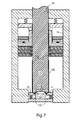
- the bottom 32 B of the container body 10 C is shaped between the profiled cooperating elements of the tips 16 of the redraw punch 15 at its leading end 17 , the bottom domer 22 and the outer retaining ring 21 (which is yieldably supported by the element 23 C, preferably a spring, and is free to move under the force of the redraw punch 15 towards the domer 22 to a final position as shown in FIG. 7 ).
- the deformation of the metal thereby produced provides the container body 10 C with a shaped bottom end.
- the profile thereby imparted is effective to provide the container with greater rigidity and to make it better able to resist outward forces produced by liquids under pressure (e.g. carbonated beverages) eventually held within the container.
- the shaped but untrimmed container body thus formed may then be removed from the apparatus by conventional removal equipment (not shown) after the redraw punch 15 has been raised and withdrawn from the container body.
- the apparatus may be provided with a gripping or holding device that holds the container body as the redraw punch 15 is withdrawn upwardly, and the same device or another may remove the untrimmed container body, thus liberated, from the apparatus.
- the container body may then be subjected to a conventional trimming operation at the open end to provide the container body with a desired length, and then a necking operation (shaping of the open end of the container), coating and/or decorating steps, pre-filling (if appropriate) and closure (incorporation of a generally flat lid element at the open end of the container body to produce a complete container). These steps are carried out in other apparatus and are conventional, and thus not illustrated.
- the combined draw punch and redraw die 13 is held fixed and immovable throughout all of the illustrated steps of the method by virtue of being rigidly mounted on the supporting structure 18 of the apparatus.
- the redraw punch 15 may be kept relatively short because the redraw starts from an inverted cup configuration.
- the redraw punch is normally supported at its upper end, e.g. by a rod extending from a piston and cylinder device (not shown), the shorter the punch, the less it will be subject to sideways movement and play at the tip 16 .
- FIGS. 8A and 8B show an apparatus equivalent to that of FIG. 1 .
- FIG. 8A shows an apparatus equivalent to that of FIG. 1 .
- FIG. 8B shows an apparatus equivalent to that of FIG. 1 .
- FIG. 8B illustrates a modification of the apparatus of FIG. 8A intended to commence a forming operation using a pre-drawn cup 100 rather than a pre-cut flat blank 10 .
- the supporting structure 18 have to be made longer, but also the punch 15 has to be made longer by an amount X (the height of the initial cup). This would increase the likelihood of uncontrolled play and flexing during the forming operation.
- the ironing rings 20 may be placed closely together, and the domer 22 may be positioned as close as possible to the ironing rings, leaving only sufficient clearance to allow the untrimmed container body 10 C to be removed from the apparatus.
- the redraw punch 15 is supported somewhat against lateral flexing by the inner surface of the redraw holder 14 , which closely surrounds the outer surface of the punch, and further support for the punch may be provided by the narrow aperture 40 in the supporting structure 18 through which the punch extends.
- FIG. 9A is a photograph showing a container body at various stages of formation according to a previous shaping method
- FIG. 9B shows a container body at equivalent stages of preparation according to the shaping method described above in connection with FIGS. 1 to 7 .
- the cup shown on the extreme left hand side is in an upturned position compared to the other stages shown in the photograph, i.e. in the forming operation, the cup would start with the open end facing up in order to form the other intermediate stages shown to its right.
- This initial cup is formed in other equipment.
- FIG. 9B the initial cup on the left is shown in the correct orientation, and is formed during a first stage of the method in the apparatus shown. The inversion of the cup caused by the redraw operation is clearly apparent.
- the draw and redraw steps may be carried out as quickly as just the draw operation of a conventional container body fabrication apparatus. This is because of the shorter travel of the redraw punch 15 (by an amount equivalent to the height of the cup).
- the apparatus of the exemplary embodiments may preferably operate at a throughput speed of 200-700, more preferably, 400-500 containers per minute.
- the diameter of the pre-formed metal blank is preferably within the range of 3-24 inches (7.6-61 cm), more preferably 3-12 inches (7.6 to 30.5 cm), more even more preferably 4.5-8 inches (11.4 to 20.3 cm).
- the initial metal gauge of the blanks is preferably 0.007-0.08 inches (0.178-2.03 mm), more preferably 0.009-0.025 inches (0.229-0.635 mm).
- the cup/redraw cup height is preferably 0.5-12 inches (1.3-30.5 cm), more preferably 1-6 inches (2.5-15.2 cm), and the cup/redraw cup diameter is preferably 0.75-6 inches (1.3-15.2 cm), more preferably 1-4 inches (2.5-10.2 cm).
- the force required to carry out the draw or redraw operations is normally 1,000 to 10,000 lb.f., more preferably 1,500-7,000 lb.f.
- FIGS. 10 to 15 illustrate alternative exemplary embodiments.
- Each of these drawings is a composite view showing the left hand side of one exemplary embodiment and the right hand side of another exemplary embodiment. The composite views are provided in this way so that steps in the methods, and apparatus corresponding to those steps, can be easily compared and contrasted.
- FIG. 10 of these additional drawings the entire apparatus is shown, including three sets of ironing rings, a bottom domer and a retaining ring.
- FIGS. 11 to 15 show only the upper part of the apparatus for simplicity terminating at the first ironing ring, but it will be appreciated that the apparatus still includes the additional ironing rings, domer and retaining ring of FIG. 10 .
- the right hand apparatus operates in much the same way as the apparatus of the previous embodiments.
- the left hand apparatus has been modified to combine the operations of the draw die and redraw holder.
- Similar elements employed in the two embodiments are identified by the same reference numerals but with a lower case letter “a” or “b” appended thereto to represent embodiment A or embodiment B, respectively. It should be noted that these lower case identifiers are not to be confused with upper case identifiers (“A”, “B”, etc.) used with the reference numerals earlier in this description and drawings. The operation of the right hand apparatus (apparatus A) will be described first.
- FIG. 10 shows the start of a shaping operation with a flat metal container blank 10 a resting on an annular draw holder 11 a and the top of a combined draw punch & redraw die 13 a .
- the blank 10 a is not clamped so as to allow insertion of the blank into the apparatus.
- draw die 12 a is moved downwardly to clamp the blank 10 a around its periphery.
- the draw die 12 a and draw holder 11 a are moved downwardly to draw the blank into an inverted cup shape, the figure showing an intermediate stage of this operation.
- FIG. 11 shows the start of a shaping operation with a flat metal container blank 10 a resting on an annular draw holder 11 a and the top of a combined draw punch & redraw die 13 a .
- draw die 12 a is moved downwardly to clamp the blank 10 a around its periphery.
- the draw die 12 a and draw holder 11 a are moved downwardly to draw the blank into an inverted cup shape, the
- FIG. 14 shows the completion of the redraw step and the commencement of the ironing operation whereby the redrawn container body positioned on the lower end of the redraw punch 15 a pushes the container body through the ironing successive rings 20 a to cause thinning and elongation of the container body side wall.
- Bottom end doming of the container body (not shown) is then carried out when the blank 10 a is pushed onto the domer 22 a and redraw ring 21 a as in the previous embodiment.
- the completed container body is then removed from the redraw punch 15 a as the punch is raised and is removed from the apparatus as before.
- the draw die 12 a and the redraw holder 14 a are separate elements that are moved by actuators independently.
- the draw die 12 b and redraw holder 14 b are mutually rigidly attached via annular connector 100 b and are both operated by a single actuator (not shown).
- the axial length of the connector 100 b is made such that, when the draw operation is complete as shown in FIG. 13 , the redraw holder 14 b clamps the blank 10 b with suitable force against the combined draw punch & redraw die 13 b .
- the effect is the same as that obtained with the separate elements 12 a and 14 a of apparatus A, but by means of a single element made up of draw die 12 b , redraw holder 14 b and connector 100 b .
- the advantage of this is that it reduces the number of separate components in the apparatus, simplifies control of the components (movement during the cup drawing step and pressure application during the redraw step), and reduces the space requirement inside and around the apparatus because fewer actuators (not shown) are required.
- FIGS. 16 to 22 are again split drawings with apparatus A (the same as apparatus A of FIGS. 10 to 15 ) shown on the right hand side, and a further apparatus C shown on the left hand side. Again, the full apparatus is shown in FIG. 16 , but just the top part is shown for simplicity in FIGS. 17 to 21 .
- FIG. 22 is a top plan view, partly in cross-section, of the apparatus C (alone) showing how a narrow coil of sheet metal is fed into and out of the apparatus. The cross-section is taken immediately above the upper end of frame 18 c and thus shows the redraw punch 15 c in cross-section while omitting elements above this position (e.g. an actuator for the punch).
- apparatus C functions in much the same way as apparatus B of FIGS. 10 to 15 in that redraw holder 14 c and draw die 12 c are fixedly held together, but with a suitable vertical separation, by connector 100 c .
- an annular blank cutter 105 is attached to the frame 18 c adjacent to the annular draw holder 11 c .
- the cutter 105 has an upper surface 106 incorporating a cut edge 107 at its inner periphery. The cut edge 107 is slightly raised relative to the upper surface of the adjacent draw holder 11 c when in its uppermost position.
- the cutter 105 is immovable relative to the frame 18 c and the movable parts around it are shaped so that contact with the cutter is avoided as they move.
- draw holder 11 c has an annular undercut 110 allowing the holder to rise to the desired vertical height before descending during the drawing step.
- Draw die 12 c and connector 100 c have a combined annular cut-out 111 that allows these elements to descend during the draw step without contacting the cutter 105 .
- Draw die 12 c has a sharp outer edge that is capable of cutting a metal blank out of sheet when forced against the cut edge 106 .
- the combined draw punch & redraw die 13 c is mounted on a horizontal base ring 113 c , similar to ring 113 a of apparatus A, supported by and fixed to a horizontal step within the frame, except that it has a periphery 114 that terminates short of the adjacent member of the frame 18 c to leave an annular gap 115 that accommodates the downwardly-extending part of the periphery of the draw holder 11 c (provided to accommodate the undercut 110 ) as shown best in FIG. 19 .
- the apparatus is not supplied with pre-cut metal blanks, but is fed with a continuous sheet 120 of metal as best shown in the plan view of FIG. 22 rather than round metal blanks as in the earlier embodiments.
- Sheet metal 120 is fed from a supply coil 121 and its skeleton is withdrawn to form a discard coil 122 .
- the coils are supported on arms 123 extending from the frame 18 c of the apparatus holding spindles 124 and 125 for the coils.
- the stepwise movement of the sheet through the apparatus is driven by coiler motor 126 and optionally a driver motor 127 and the desired path through the apparatus is ensured by pairs of horizontal rollers 128 and 129 (only an upper roller is shown in each case) on either side of the apparatus.
- the frequency and extent of the stepwise feeding motion is controlled to correspond with the steps carried out by the apparatus by means of controller 130 .
- the metal sheet 120 is fed into the apparatus from the position of the viewer between open parts of the frame 18 c .
- the sheet 120 is slightly wider in the transverse direction than the desired diameter of the blank 10 c .
- the annular blank cutter 105 and adjacent draw die 12 c stamp a circular blank 10 c out of the metal sheet 120 as the draw die descends to clamp onto the periphery of the circular blank. This leaves an unclamped sheet residue 120 A surrounding the blank 10 c in the form of a metal sheet with a hole 131 corresponding to the diameter of the blank 10 c .
- the residue 120 A Since the residue 120 A remains in sheet form, it can be used to advance the unused parts of the sheet 120 through the apparatus after the cut out blank 10 c has been subjected to the steps required for formation of a container body and the punch redraw punch 15 c has been retracted to its uppermost starting position.
- This embodiment has the advantage that pre-formed circular blanks do not have to be provided to the operator and fed into the apparatus, which may be desirable in some cases, while providing a mechanism for uncoiling coiled metal sheet, feeding it into the apparatus, and coiling the residue.
- the sheet 120 is pre-cut to a suitable width that is larger than the diameter of the blanks but smaller than the entrance to the apparatus between elements of the frame 18 c .
- the width is only large enough to prevent breakage or folding of the residue 120 A as it is removed from the apparatus.
- a coil of suitable width may be cut from a wider coil by the use of conventional coil-slitting apparatus. This can be done before or after the metal is supplied to the operator of the container-forming apparatus.
- apparatus C operates in the same way as apparatus B as shown in FIGS. 10 to 15 .
Abstract
Description
- This application is a continuation-in-part of prior co-pending U.S. patent application Ser. No. 11/975,926 filed on Oct. 22, 2007 by applicants named herein. The entire contents of the aforesaid application are specifically incorporated herein by this reference.
- I. Field of the Invention
- This invention relates to the production of container bodies made of metal. More particularly, the invention relates to apparatus and methods for forming untrimmed beverage container (can) bodies, particularly such bodies made of aluminum and aluminum alloys. Untrimmed bodies of this kind are subsequently trimmed and provided with a container end closure to create a completed container.
- II. Background Art
- Beverage container bodies are generally produced in two forming steps carried out in different machines. The first step involves cutting a flat circular blank from a sheet of metal and creating a shallow cup from the blank in a drawing operation. The second step involves reducing the cup diameter and thinning and elongating the sides of the cup to produce a full-length container body employing redrawing and ironing operations. Ironing involves passing the redrawn cup (supported on a punch, mandrel or the like) through a number of dies or rings of progressively smaller diameter to thin and stretch the sidewalls of the container body. The container body is then normally trimmed and shaped at the open end, lacquered or painted, filled, and provided with a closure in the form of a generally flat can lid. The metal for the container bodies is normally supplied to the fabricator in the form of a metal coil or roll and the fabricator stamps circular flat metal pieces or blanks from the metal roll as a first step of the overall container body forming operation. This produces a significant amount of metal waste in the form of a flat web with punched-out circular holes. The metal waste is normally returned to the metal supplier for recycling, but this is an inefficient procedure because it involves transporting a certain percentage of metal first to the fabricator and then from the fabricator back to the metal supplier. In circumstances where the metal fabricator and can body producer are located in different countries, some governments apply taxes or duties on both metal sheet imports and scrap metal exports, thus further reducing the economic benefit of supplying the metal in the form of continuous sheet.
- Even when it is acceptable or desirable to provide the metal in the form of a coil or roll, the separate blank-forming operation involves the use of specialized metal stamping equipment and requires a separate initial step.
- In addition, the indicated two-step container-forming procedure is not fully efficient because an intermediate product (a shaped cup) is created in one kind of apparatus and is then transferred to a second kind of apparatus (a redraw and ironing machine) for the second stage of the process. This can result in significant wastage of both time, factory floor space and invested capital. Moreover, the redraw and ironing operations often cannot produce container bodies of consistent thickness and unwrinkled appearance because there is often an unwanted degree of play between the punch, die and ironing elements that creates non-uniformity in production. This play is often produced because the redraw punch operates under considerable force and the operational end is necessarily positioned at quite a distance from the driven end where the punch is held and receives its driving force (e.g. from a hydraulic piston). Consequently, a degree of flexing of the punch may take place that results in play at the operational end.
- Attempts have been made in the past to overcome some or all of these disadvantages, but problems still persist.
- For example, U.S. Pat. No. 3,167,044 granted on Jan. 26, 1965 to Henrickson discloses a process in which flat round metal blanks or work pieces are pre-formed and then fed into can body-forming apparatus. The can body is then produced by a single drawing step, followed by ironing stages and a bottom-forming step. Accordingly, the procedure still requires a multi-stage operation, even though the use of round metal blanks may reduce metal waste generated during the forming process.
- U.S. Pat. No. 3,733,881 granted on May 22, 1973 to Donald C. Grigorenko discloses apparatus that drawing, reverse redrawing, and ironing steps carried out essentially in a single operation. In this case, however, round metal blanks are punched out of a continuous strip of metal as a first step. Additionally, the apparatus is arranged such that the various moving components may encounter a high degree of play, therefore resulting in a lack of uniformity in the can bodies thus produced, or even a degree of metal wrinkling or seaming during the drawing and ironing procedures.
- U.S. Pat. No. 4,732,031 granted on Mar. 22, 1988 to Bulso, Jr. et al. discloses apparatus to which creates a can body by a drawing, reverse redrawing and ironing operations. However, the ironing operation is carried out in a different machine than the drawing and reverse redrawing operations.
- There is therefore a need for an improved beverage container forming method and apparatus that overcomes at least some of the disadvantages mentioned above.
- An exemplary embodiment provides apparatus for making an untrimmed container body from a pre-cut metal blank. The apparatus includes shaping tools and actuators for operating the tools with sufficient force for shaping the blank into an untrimmed container body, and a support structure for supporting the shaping tools and actuators while allowing necessary movements of some of the tools. The support structure, which may be made of steel, cast-iron, aluminum or other metal or strong material, is preferably sufficiently strong to resist flexing when subjected to the forces required for container production, and preferably provides a rigid support so that various tools can be held without movement, flexing or play as the container is formed.
- The shaping tools include a combined draw punch and redraw die having an annular body including an inner surface, an outer surface and an end surface at an operational end of the annular body that initially contacts the blank. The end surface and the outer surface together function in use as a draw punch, and the inner surface (at least immediately adjacent to the end surface) functions in use as a redraw die. The annular body is fixed (preferably rigidly) on the support structure against movement relative thereto during use. Despite its lack of movement relative to the support structure, the annular body may function as a draw punch because it cooperates with a movable draw die that shapes the blank on the draw punch. The draw die preferably contacts the surface of the blank opposite to the surface contacting the draw punch and has a die surface dimensioned to encircle the outer surface of the annular body of the draw punch with a spacing effective for cupping of the blank therebetween. The draw die is movable in use along the outer surface of the annular body from the operational end towards an open opposite end, thus forming a cup from the blank.
- The tools further include a redraw punch comprising a cylinder having an outer surface to dimensioned to penetrate the operational end of the annular body at a spacing from the inner surface thereof effective for redrawing the cup. The redraw punch is thus movable at its leading end into the open end of the annular body to invert the cup to thereby form an inverted redrawn cup having an open end and a closed end supported on the redraw punch. One or more ironing rings are positioned adjacent to the open opposite end of the annular body and are aligned with the annular body, thus being positioned to iron an outer surface of the inverted redrawn cup supported on the leading end of the redraw punch after the leading end emerges from the open end of the annular body, to thereby lengthen the sides of the inverted redrawn cup to form an untrimmed container body having a closed end.
- The tools also preferably include a container body end shaper positioned in spaced alignment with the one or more ironing rings to contact the closed end of the untrimmed container body supported on the leading end of the redraw punch, the shaper being profiled to shape the closed end when the closed end is forced thereagainst by the redraw punch.
- The apparatus preferably includes a holding or gripping device for gripping the untrimmed container body as the redraw punch is withdrawn from it, and a device for removing the thus-liberated untrimmed container body from the apparatus for further processing.
- By commencing the forming operation from a pre-cut flat metal blank, the distance between the leading end of the redraw punch and the operational end of the annular body of the combined draw punch and redraw die can be kept small (just wide enough to receive a flat metal blank fed in from one side). This means that the supporting structure and the redraw punch can be made shorter that would be the case if a pre-formed drawn cup were used as a starting point. A shorter supporting structure and, particularly, a shorter redraw punch means that the apparatus is less likely to encounter flexing and play under the forces required for the forming operations, thus producing more regular container bodies. The need for a separate cupping apparatus is also avoided because initial cupping is integrated as part of the operation. Furthermore, by commencing from a pre-cut metal blank rather than a flat metal sheet, the operator of the apparatus may be supplied with blanks pre-cut at or near the fabricator of metal sheet, thus avoiding the need to transport waste metal over large distances and across country borders.
- The tools of the above apparatus may further include an annular draw holder confronting to the annular draw die and adapted to grip a periphery of the blank between the annular draw holder and the annular draw die with a force that allows the periphery to be withdrawn and guided during drawing of said blank. As the blank is drawn into a shallow cup, the annular draw holder keeps the periphery of the blank in contact with the annular draw die, but nevertheless allows the perhiphery to be pulled out of such contact as the walls of the cup being formed. The force applied to the draw holder may be applied by means of a spring or other means, such as a hydraulic or pneumatic piston and cylinder arrangement.
- The tools of the apparatus also preferably include an annular redraw holder confronting the operational end of the combined draw punch and redraw die. This is adapted to grip an outer part of the initially-formed cup between the holder and the operational end of the combined draw punch and redraw die with a force that keeps the outer part to be held against the operational end but allows the outer part to be withdrawn and guided during redrawing of the cup. The annular redraw holder may also have an inner annular surface dimensioned to surround and support the outer surface redraw punch, thus assisting with the minimization of flexing of the leading end of the redraw punch by providing lateral support as the redraw punch performs the redraw operation. For similar reasons, the redraw punch may pass through a narrow aperture in the supporting structure, the sides of which provides guidance and support for the redraw punch as it carries out the redraw and ironing operations. The redraw punch passes through the aperture and is supported at and driven from an end opposite to the operational end of the redraw punch. The redraw punch preferably has a length no greater than the distance between the aperture and the end shaper of the container body.
- In order to allow further minimization of the length of the redraw punch, the end shaper may be spaced from an end one of the one or more ironing rings by a distance that provides only minimal clearance between the open end of the untrimmed container body thus formed and the end one of the ironing rings when the redraw punch is extended fully. Similarly, the ironing rings, when there is more than one, are preferably positioned as close as possible together and to the open end of the annular body. There is therefore minimal spacing between these elements. The apparatus of
claim 1, wherein said redraw punch passes through an aperture in said support structure and is supported at and driven from an end opposite to said operational end. - Another exemplary embodiment of the invention provides a method of making an untrimmed container body from a pre-cut metal blank. The method involves cupping a pre-cut metal blank by positioning the blank against an immovable draw punch comprising an annular body having an outer surface and an inner surface adapted to form a redraw die, and drawing a periphery of the blank over the outer surface of the draw punch with an encircling draw die to form a cup having an open end, a closed end and an interior. The cup is then inverted and redrawn by forcing a redraw punch into the closed end of the cup to draw the closed end through the redraw die until the cup is inverted to form an inverted cup with a closed end supported on the punch. The inverted cup while supported on the redraw punch is then passed through one or more ironing rings to lengthen the inverted cup to form an untrimmed container body having a closed end. The closed end of the untrimmed container body is then shaped by engaging the closed end of the untrimmed container body with one or more end shaping tools while supported on the redraw punch. Finally, the redraw punch is removed from the untrimmed container body.
- The initial cup is drawn in a direction away from the redraw punch that contacts the closed end of the cup, i.e. such that the open end faces away from the redraw punch. Consequently, the redraw punch cause the initial cup to be inverted as it is redrawn. That is to say, after the redraw operation, the redraw punch passes through the open end of the inverted redrawn cup and supports the inverted redrawn from the interior. The draw punch and redraw die is preferably held immobile by fixing it rigidly to a supporting structure. At the start of the method, the leading end of the redraw punch is preferably positioned close to the operational end of the combined draw punch and redraw die with just enough clearance to allow a pre-cut metal blank to be positioned therebetween when introduced laterally between these elements.
- The apparatus and method are preferably arranged in such a way that the drawing and ironing operations can be carried out with a minimum amount of play in the apparatus such that uniformity of the container bodies, such as uniform wall thickness, can be ensured. All of the initial cupping, the redraw, ironing and end shaping are carried out in a single apparatus and the redraw punch requires only a single punch stroke to achieve the necessary redraw, ironing and end shaping steps.
- Another exemplary embodiment of the invention provides apparatus for making an untrimmed container body from a pre-cut metal blank. The apparatus comprises shaping tools and actuators for operating the tools with sufficient force for shaping the blank into an untrimmed container body, and a support structure for supporting the shaping tools and actuators while allowing necessary movements of some of the tools. The shaping tools include: a combined draw punch and redraw die comprising an annular body having an inner surface, an outer surface and an end surface defining an opening at an operational end of the annular body that initially contacts the blank, the end surface and the outer surface together functioning in use as the draw punch, and the inner surface functioning in use as the redraw die, the annular body being fixed on the structure against movement relative thereto during use; a draw die having a die surface dimensioned to encircle the outer surface of the annular body at a spacing effective for cupping of the blank, the draw die being movable in use along the outer surface from the operational end to form a cup from the blank; a redraw punch comprising a cylinder having an outer surface dimensioned to penetrate the opening at the operational end of the annular body with a spacing from the inner surface effective for redrawing the cup, the redraw punch being movable at a leading end thereof into the opening and through the annular body to invert the cup to thereby form an inverted redrawn cup having an open end and a closed end; and one or more ironing rings aligned with the annular body and positioned to iron an outer surface of the inverted redrawn cup supported on the leading end of the redraw punch after the leading end passes through and emerges from the annular body, to thereby lengthen the inverted redrawn cup to form an untrimmed container body having a closed end.
- The tools preferably further include an annular redraw holder operationally connected to the draw die such that, when the draw die has completed a drawing operation on the metal blank to form a cup, the redraw holder confronts the operational end of the combined draw punch and redraw die and holds an outer part of the cup against the combined draw punch and redraw die with a force that allows the outer part to be withdrawn and guided during redrawing of the cup.
- Preferably, the tools further include an annular draw holder confronting the annular draw die and adapted to grip a periphery of the blank between the annular draw holder and the annular to draw die with a force that allows the periphery to be withdrawn and guided during drawing of the blank.
- Still more preferably, the tools include a container body end shaper positioned in spaced alignment with the one or more ironing rings to contact the closed end of the untrimmed container body supported on the operational end of the redraw punch, the shaper being profiled to shape the closed end when the closed end is forced thereagainst by the redraw punch.
- According to yet another exemplary embodiment, there is provided a method of making an untrimmed container body from a pre-cut metal blank, comprising: cupping a pre-cut metal blank by positioning the blank against an immovable draw punch comprising an annular body having an inner surface adapted to form a redraw die and an outer surface, and drawing a periphery of the blank over the outer surface of the draw punch with an encircling draw die to form a cup having an open end, a closed end and an interior; inverting and redrawing the cup by forcing a redraw punch into the closed end to draw the closed end through the redraw die until the cup is inverted to form an inverted cup supported on the punch, the inverted cup having a closed end; passing the inverted cup while supported on the redraw punch through one or more ironing rings to lengthen the inverted cup to form an untrimmed container body having a closed end; and withdrawing the punch from the untrimmed container body.
- The method preferably includes shaping the closed end of the untrimmed container body by engaging the closed end of the untrimmed container body with one or more end shaping tools while supported on the redraw punch. More preferably, before redrawing the cup, part of the cup is gripped between a redraw holder and the draw punch, the redraw holder being operationally connected to the draw die such that the redraw holder is moved into position to grip the cup as the draw die completes the cupping of the blank.
- Yet another exemplary embodiment provides apparatus for making an untrimmed container body from metal sheet, comprising: shaping tools and actuators for operating the tools with sufficient force for cutting a metal blank from the sheet and shaping the blank into an untrimmed container body; and a support structure for supporting the shaping tools and actuators while allowing necessary movements of some of the tools; wherein the shaping tools include: a combined draw punch and redraw die comprising an annular body having an inner surface, an outer surface and an end surface defining an opening at an operational end of the annular body that initially contacts the metal blank, the end surface and the outer surface together functioning in use as the draw punch, and the inner surface functioning in use as the redraw die, the annular body being fixed on the structure against movement relative thereto during use; a draw die having a die surface dimensioned to encircle the outer surface of the annular body at a spacing effective for cupping of the blank, the draw die being movable in use along the outer surface from the operational end to form a cup from the blank; a redraw punch comprising a cylinder having an outer surface dimensioned to penetrate the opening at the operational end of the annular body with a spacing from the inner surface effective for redrawing the cup, the redraw punch being movable at a leading end thereof into the opening and through the annular body to invert the cup to thereby form an inverted redrawn cup having an open end and a closed end; and one or more ironing rings aligned with the annular body and positioned to iron an outer surface of the inverted redrawn cup supported on the leading end of the redraw punch after the leading end passes through and emerges from the annular body, to thereby lengthen the inverted redrawn cup to form an untrimmed container body having a closed end.
- In this embodiment, the tools include an annular cutter fixed to the support structure, the cutter having an annular cutting edge operationally positioned relative to an outer periphery of the draw die to cut the blank from the metal sheet when the draw die is moved relative to the cutting edge with the sheet positioned therebetween. The embodiment also preferably includes equipment for passing the metal sheet through the apparatus at a position between the cutter and the draw die. In this way, the equipment may be fed with metal sheet, preferably from a coil, and the blanks may be cut from the sheet just as the forming of the blanks commences.
- Therefore, this exemplary embodiment includes a method of making an untrimmed container body from a metal sheet, comprising: cupping a metal blank cut from the sheet by positioning the blank against an immovable draw punch comprising an annular body having an inner surface adapted to form a redraw die and an outer surface, and drawing a periphery of the blank over the outer surface of the draw punch with an encircling draw die to form a cup having an open end, a closed end and an interior; inverting and redrawing the cup by forcing a redraw to punch into the closed end to draw the closed end through the redraw die until the cup is inverted to form an inverted cup supported on the punch, the inverted cup having a closed end; passing the inverted cup while supported on the redraw punch through one or more ironing rings to lengthen the inverted cup to form an untrimmed container body having a closed end; and withdrawing the punch from the untrimmed container body.
- The metal blank can be cut from the metal sheet just as the blank is positioned against the immovable draw punch. Preferably the sheet has greater width than a diameter of the metal blank, and residue from the metal sheet is removed after the withdrawal of the punch from the untrimmed container body.
-
FIGS. 1 to 7 are simplified schematic representations of an exemplary apparatus showing various stages in the formation of an untrimmed container body from a flat metal blank; -
FIGS. 8A and 8B are representations showing apparatus according to an exemplary embodiment of the invention (FIG. 8A ), and a modification of such an embodiment intended to commence a forming operation from a pre-drawn cup (FIG. 8B ), to illustrate a preferred advantage of the exemplary embodiments; -
FIGS. 9A and 9B are photographs of container bodies at various stages of production from metal blanks,FIG. 9A showing stages in a conventional method andFIG. 9B showing stages in a method according to exemplary embodiments herein; -
FIG. 10 is a composite drawing of two further alternative exemplary embodiments, showing half of each embodiment arranged side-by-side for comparison; -
FIGS. 11 to 15 are drawings similar toFIG. 10 , but each showing different steps in the formation of a container body carried out by the apparatus; -
FIGS. 16 to 21 are drawings similar toFIGS. 10 to 15 , but showing an alternative exemplary embodiment of the invention compared with a previously-described exemplary embodiment; and -
FIG. 22 is a top plan view, partially in cross-section, of the alternative exemplary embodiment ofFIGS. 16 to 21 showing additional equipment. - The present invention makes it possible, at least in preferred embodiments, to fabricate an untrimmed beverage container body in a single apparatus using a minimum number of steps and with good precision, optionally, but not necessarily, commencing from a pre-formed round flat metal blank (sized to form an individual can body without significant waste) rather than from a flat or coiled sheet of metal.
-
FIGS. 1 to 7 of the accompanying drawings illustrate various steps in a method according to one exemplary embodiment of the invention. In these views, the apparatus is shown in a simplified form for ease of illustration and description. It will, however, be appreciated by a person skilled in the art that a significant amount of ancillary apparatus and accompanying drive equipment will be required in order to produce a functional apparatus. Preferably, the moving parts of the apparatus are driven by pneumatic or hydraulic means, or possibly by mechanical means (e.g. screw-threaded collars mounted on rotated threaded rods, or the like). This kind of supporting and additional equipment is illustrated in U.S. Pat. No. 3,733,881 mentioned above (the disclosure of which is incorporated herein by reference). - As shown in
FIG. 1 , a round flat metal blank 10 (which is preferably pre-cut or stamped from a metal sheet at another location) is positioned in the apparatus with its periphery aligned between anannular draw holder 11 and a confronting annular draw die 12. The metal blank may be introduced into the apparatus horizontally from one side (e.g. the front or rear in the orientation shown in the drawing). Inwardly of thetools metal blank 10 is also positioned between a combined draw punch & redraw die 13 and a confronting annular redrawholder 14. Still further inwardly, the blank 10 is aligned with a cylindrical redrawpunch 15 having a profiledtip 16 at an annularleading end 17 thereof. The combined draw punch & redraw die 13 is rigidly mounted on aframe 18, acting as a rigid supporting structure, so that it is supported by and immovable relative to the frame. This ensures that the combined punch & redraw die 13 is subjected to no, or only minimal, movement, flexing and play during the various forming steps. The other elements just mentioned are movable, as will be explained later. - The apparatus shown in
FIG. 1 also includes a set of immovable ironing rings 20 of progressively smaller inner diameter in the downward direction of the drawing, an annularouter retaining ring 21, and acontainer bottom domer 22. Together, thering 21 anddomer 22 form a shaping tool, or end shaper, for the closed end of the untrimmed container body formed in the earlier steps. These various parts form the principal shaping tools of the apparatus and are mounted on the supporting structure for operation in the manner shown in the subsequent figures. The redrawpunch 15 is held at its upper end (not shown) opposite to theleading end 17 and is moved in an upward or downward direction by a hydraulic piston/cylinder device, or an equivalent actuator (not shown). Thedomer 22 is fixed in place on the supportingstructure 18 and is immovable during the various operations but the retainingring 21 is movable. Various load-producingelements - During the initial drawing operation, annular draw die 12 is driven with considerable force by a drive element (not shown), e.g. a hydraulic piston/cylinder combination. The redraw
holder 14 is also driven by an actuator (not shown) so that it may be raised against the force ofelement 23A to allow the flat metal blank 10 to be inserted into the apparatus. Thereafter, theholder 14 may be allowed to descend onto the surface of the blank. - It will be noted that the combined draw punch & redraw die 13 is in the form of a single
annular body 25 having aninner surface 26, anouter surface 27 and anend surface 28 at an operational (upper) end 29 of the tool. As will be more apparent from the subsequent description, theend surface 28 and theouter surface 27 co-operate to form a draw punch, and theinner surface 26, at least at its upper end that has a smaller diameter than the remainder, forms a redraw die. -
FIG. 2 shows the blank 10 clamped firmly between thedraw holder 11, draw die 12, the combined draw punch & redraw die 13 and the redrawholder 14 at the start of the shaping operation. The clamping is effected by downward movement of theelements FIG. 1 . It will be noticed fromFIGS. 1 and 2 that the redrawholder 11 has a slight recess at its inner end that exactly matches the outer diameter of the blank 10. This facilitates the proper alignment of the blank in the apparatus. -
FIG. 3 represents an intermediate stage of a first or initial step of the shaping operation in which the draw die 12 is moved downwardly with considerable force from an actuator (not shown). Thedraw holder 11, presses the periphery of the blank against the surface of the draw die 12 under the action of theelement 27. The draw die 12 has aninner surface 30 shaped and dimensioned to encircle theouter surface 27 with a spacing effective for cupping the blank 10. The draw die 12 moves along theouter surface 27 of the combined draw punch and redraw die 13 and commences to draw the periphery of the blank 10 into the shape of cup, forming asidewall 31 from the blank 10. As the initial cupping operation proceeds, the periphery of the blank is progressively drawn out of the cooperative gripping engagement between the draw die 12 and thedraw holder 11. The completion of this operation is shown inFIG. 4 in which themetal blank 10 has been drawn into a shallow-sidedinitial cup 10A having an open end facing down (away from the redraw punch 15). - The next step of the method is shown in
FIG. 5 in which the redrawpunch 15 is forced (as shown by the arrow) into the bottom 32 of theinitial cup 10A ofFIG. 4 to penetrate the openoperational end 29 of theannular body 25, thus initiating a redraw operation to produce a redrawncup 10B of smaller diameter than the initially drawncup 10A. As this operation proceeds, the periphery of the initially drawncup 10A is gradually pulled between the cooperating surfaces of the redrawholder 14 and the combined draw punch & redrawdie 13. The redrawpunch 15 has an outer surface 35 that is of smaller diameter than that of theinner surface 26 of the combined punch and redraw die 13 by a dimension similar to the metal thickness effective for the illustrated redrawing and inversion step. As already noted, theinner surface 26 adjacent to theoperational end surface 28 may be of slightly smaller diameter than at positions further along the annular body 25 (as shown) to avoid undue friction between the inverting cup and theannular body 25 as the operation proceeds. - Referring to
FIG. 6 , as the redrawpunch 15 is moved downwardly even further and passes through the open opposite (lower) end of theannular body 25. The inverted redrawncup 10B is supported on the leadingend 17 of thepunch 15 and it is caused to pass through the series of progressively narrower ironing rings 20, thereby elongating and thinning the sidewalls 31B of redrawncup 10B to form anelongated container body 10C. The operational surfaces of the ironing rings may be fed with a suitable lubricant during the ironing stage of the operation, e.g. from suitable conduits or glands (not shown). - As shown in
FIG. 7 , at the end of the downward stroke of the redrawpunch 15, the bottom 32B of thecontainer body 10C is shaped between the profiled cooperating elements of thetips 16 of the redrawpunch 15 at its leadingend 17, thebottom domer 22 and the outer retaining ring 21 (which is yieldably supported by theelement 23C, preferably a spring, and is free to move under the force of the redrawpunch 15 towards thedomer 22 to a final position as shown inFIG. 7 ). The deformation of the metal thereby produced provides thecontainer body 10C with a shaped bottom end. The profile thereby imparted is effective to provide the container with greater rigidity and to make it better able to resist outward forces produced by liquids under pressure (e.g. carbonated beverages) eventually held within the container. - The shaped but untrimmed container body thus formed may then be removed from the apparatus by conventional removal equipment (not shown) after the redraw
punch 15 has been raised and withdrawn from the container body. For example, the apparatus may be provided with a gripping or holding device that holds the container body as the redrawpunch 15 is withdrawn upwardly, and the same device or another may remove the untrimmed container body, thus liberated, from the apparatus. - The container body may then be subjected to a conventional trimming operation at the open end to provide the container body with a desired length, and then a necking operation (shaping of the open end of the container), coating and/or decorating steps, pre-filling (if appropriate) and closure (incorporation of a generally flat lid element at the open end of the container body to produce a complete container). These steps are carried out in other apparatus and are conventional, and thus not illustrated.
- As noted earlier, the combined draw punch and redraw die 13 is held fixed and immovable throughout all of the illustrated steps of the method by virtue of being rigidly mounted on the supporting
structure 18 of the apparatus. In addition, the redrawpunch 15 may be kept relatively short because the redraw starts from an inverted cup configuration. As the redraw punch is normally supported at its upper end, e.g. by a rod extending from a piston and cylinder device (not shown), the shorter the punch, the less it will be subject to sideways movement and play at thetip 16. Thus, not only is a complete untrimmed container body created in a single apparatus, but the apparatus may be made desirably rigid at those parts subject to the greatest forces during the various operations, thereby ensuring uniformity of the resulting container bodies (wall thickness and lack of wrinkling and seeming). It is estimated that the stroke length of the redraw punch may be 5-30%, more normally 5-20%, less than that required for conventional apparatus that commences with a pre-formed cup. For example, a standard 22 inch punch stroke required for a conventional apparatus can be reduced to 18 or 19 inches in equivalent apparatus according to the exemplary embodiments. This effect is illustrated byFIGS. 8A and 8B .FIG. 8A shows an apparatus equivalent to that ofFIG. 1 .FIG. 8B illustrates a modification of the apparatus ofFIG. 8A intended to commence a forming operation using apre-drawn cup 100 rather than a pre-cut flat blank 10. To accommodate insertion of thecup 100 into the apparatus, not only does the supportingstructure 18 have to be made longer, but also thepunch 15 has to be made longer by an amount X (the height of the initial cup). This would increase the likelihood of uncontrolled play and flexing during the forming operation. - Other measures may be taken to keep the length of the redraw
punch 15 as short as possible. For example, the ironing rings 20 may be placed closely together, and thedomer 22 may be positioned as close as possible to the ironing rings, leaving only sufficient clearance to allow theuntrimmed container body 10C to be removed from the apparatus. - It will also be noted that the redraw
punch 15 is supported somewhat against lateral flexing by the inner surface of the redrawholder 14, which closely surrounds the outer surface of the punch, and further support for the punch may be provided by thenarrow aperture 40 in the supportingstructure 18 through which the punch extends. -
FIG. 9A is a photograph showing a container body at various stages of formation according to a previous shaping method, andFIG. 9B shows a container body at equivalent stages of preparation according to the shaping method described above in connection withFIGS. 1 to 7 . It is to be noted that, inFIG. 9A , the cup shown on the extreme left hand side is in an upturned position compared to the other stages shown in the photograph, i.e. in the forming operation, the cup would start with the open end facing up in order to form the other intermediate stages shown to its right. This initial cup is formed in other equipment. InFIG. 9B , the initial cup on the left is shown in the correct orientation, and is formed during a first stage of the method in the apparatus shown. The inversion of the cup caused by the redraw operation is clearly apparent. - It is found in at least some exemplary embodiments that the draw and redraw steps may be carried out as quickly as just the draw operation of a conventional container body fabrication apparatus. This is because of the shorter travel of the redraw punch 15 (by an amount equivalent to the height of the cup).
- The apparatus of the exemplary embodiments may preferably operate at a throughput speed of 200-700, more preferably, 400-500 containers per minute. Normally, the diameter of the pre-formed metal blank is preferably within the range of 3-24 inches (7.6-61 cm), more preferably 3-12 inches (7.6 to 30.5 cm), more even more preferably 4.5-8 inches (11.4 to 20.3 cm). The initial metal gauge of the blanks is preferably 0.007-0.08 inches (0.178-2.03 mm), more preferably 0.009-0.025 inches (0.229-0.635 mm). The cup/redraw cup height is preferably 0.5-12 inches (1.3-30.5 cm), more preferably 1-6 inches (2.5-15.2 cm), and the cup/redraw cup diameter is preferably 0.75-6 inches (1.3-15.2 cm), more preferably 1-4 inches (2.5-10.2 cm). The force required to carry out the draw or redraw operations is normally 1,000 to 10,000 lb.f., more preferably 1,500-7,000 lb.f.
-
FIGS. 10 to 15 illustrate alternative exemplary embodiments. Each of these drawings is a composite view showing the left hand side of one exemplary embodiment and the right hand side of another exemplary embodiment. The composite views are provided in this way so that steps in the methods, and apparatus corresponding to those steps, can be easily compared and contrasted. InFIG. 10 of these additional drawings the entire apparatus is shown, including three sets of ironing rings, a bottom domer and a retaining ring. However,FIGS. 11 to 15 show only the upper part of the apparatus for simplicity terminating at the first ironing ring, but it will be appreciated that the apparatus still includes the additional ironing rings, domer and retaining ring ofFIG. 10 . Nevertheless, it would be possible to provide equivalent apparatus without the domer and retaining ring (but including multiple ironing rings, as needed) in those cases where a container body without a shaped lower end is required. In such a case, the lower end of the container body would be flat. - In
FIGS. 10 to 15 , the right hand apparatus (apparatus A) operates in much the same way as the apparatus of the previous embodiments. However, the left hand apparatus (apparatus B) has been modified to combine the operations of the draw die and redraw holder. Similar elements employed in the two embodiments are identified by the same reference numerals but with a lower case letter “a” or “b” appended thereto to represent embodiment A or embodiment B, respectively. It should be noted that these lower case identifiers are not to be confused with upper case identifiers (“A”, “B”, etc.) used with the reference numerals earlier in this description and drawings. The operation of the right hand apparatus (apparatus A) will be described first. -
FIG. 10 shows the start of a shaping operation with a flat metal container blank 10 a resting on anannular draw holder 11 a and the top of a combined draw punch & redraw die 13 a. In this stage of the operation, the blank 10 a is not clamped so as to allow insertion of the blank into the apparatus. InFIG. 11 , draw die 12 a is moved downwardly to clamp the blank 10 a around its periphery. InFIG. 12 , the draw die 12 a and drawholder 11 a are moved downwardly to draw the blank into an inverted cup shape, the figure showing an intermediate stage of this operation. InFIG. 13 , the draw operation is complete after descent of the draw die 12 a and thedraw holder 11 a, and the redrawholder 14 a is subsequently moved downwardly to clamp the cupped blank. InFIG. 14 , cylindrical redrawpunch 15 a is moved downwardly to redraw and invert the cupped blank between the redrawpunch 15 a and the inner edge of the combined draw punch & redraw die 13 a.FIG. 15 shows the completion of the redraw step and the commencement of the ironing operation whereby the redrawn container body positioned on the lower end of the redrawpunch 15 a pushes the container body through the ironingsuccessive rings 20 a to cause thinning and elongation of the container body side wall. Bottom end doming of the container body (not shown) is then carried out when the blank 10 a is pushed onto the domer 22 a and redrawring 21 a as in the previous embodiment. The completed container body is then removed from the redrawpunch 15 a as the punch is raised and is removed from the apparatus as before. - In the right hand apparatus A shown in
FIGS. 10 to 15 , the draw die 12 a and the redrawholder 14 a are separate elements that are moved by actuators independently. In contrast, in apparatus B shown at the left hand side of the figures, while the steps are essentially the same, the draw die 12 b and redrawholder 14 b are mutually rigidly attached viaannular connector 100 b and are both operated by a single actuator (not shown). The axial length of theconnector 100 b is made such that, when the draw operation is complete as shown inFIG. 13 , the redrawholder 14 b clamps the blank 10 b with suitable force against the combined draw punch & redraw die 13 b. Thus, the effect is the same as that obtained with theseparate elements holder 14 b andconnector 100 b. The advantage of this is that it reduces the number of separate components in the apparatus, simplifies control of the components (movement during the cup drawing step and pressure application during the redraw step), and reduces the space requirement inside and around the apparatus because fewer actuators (not shown) are required. - A further alternative embodiment is shown in
FIGS. 16 to 22 .FIGS. 16 to 21 are again split drawings with apparatus A (the same as apparatus A ofFIGS. 10 to 15 ) shown on the right hand side, and a further apparatus C shown on the left hand side. Again, the full apparatus is shown inFIG. 16 , but just the top part is shown for simplicity inFIGS. 17 to 21 .FIG. 22 is a top plan view, partly in cross-section, of the apparatus C (alone) showing how a narrow coil of sheet metal is fed into and out of the apparatus. The cross-section is taken immediately above the upper end offrame 18 c and thus shows the redrawpunch 15 c in cross-section while omitting elements above this position (e.g. an actuator for the punch). - As shown in
FIGS. 16 to 21 , apparatus C functions in much the same way as apparatus B ofFIGS. 10 to 15 in that redrawholder 14 c and draw die 12 c are fixedly held together, but with a suitable vertical separation, byconnector 100 c. In this embodiment, however, an annularblank cutter 105 is attached to theframe 18 c adjacent to theannular draw holder 11 c. Thecutter 105 has anupper surface 106 incorporating acut edge 107 at its inner periphery. Thecut edge 107 is slightly raised relative to the upper surface of theadjacent draw holder 11 c when in its uppermost position. Thecutter 105 is immovable relative to theframe 18 c and the movable parts around it are shaped so that contact with the cutter is avoided as they move. Thus, drawholder 11 c has an annular undercut 110 allowing the holder to rise to the desired vertical height before descending during the drawing step. Draw die 12 c andconnector 100 c have a combined annular cut-out 111 that allows these elements to descend during the draw step without contacting thecutter 105. Draw die 12 c has a sharp outer edge that is capable of cutting a metal blank out of sheet when forced against thecut edge 106. The combined draw punch & redraw die 13 c is mounted on ahorizontal base ring 113 c, similar to ring 113 a of apparatus A, supported by and fixed to a horizontal step within the frame, except that it has aperiphery 114 that terminates short of the adjacent member of theframe 18 c to leave anannular gap 115 that accommodates the downwardly-extending part of the periphery of thedraw holder 11 c (provided to accommodate the undercut 110) as shown best inFIG. 19 . - In apparatus C, the apparatus is not supplied with pre-cut metal blanks, but is fed with a
continuous sheet 120 of metal as best shown in the plan view ofFIG. 22 rather than round metal blanks as in the earlier embodiments.Sheet metal 120 is fed from asupply coil 121 and its skeleton is withdrawn to form a discardcoil 122. The coils are supported onarms 123 extending from theframe 18 c of theapparatus holding spindles coiler motor 126 and optionally adriver motor 127 and the desired path through the apparatus is ensured by pairs ofhorizontal rollers 128 and 129 (only an upper roller is shown in each case) on either side of the apparatus. The frequency and extent of the stepwise feeding motion is controlled to correspond with the steps carried out by the apparatus by means ofcontroller 130. As shown inFIGS. 16 to 21 , themetal sheet 120 is fed into the apparatus from the position of the viewer between open parts of theframe 18 c. Thesheet 120 is slightly wider in the transverse direction than the desired diameter of the blank 10 c. As best shown inFIG. 17 , the annularblank cutter 105 and adjacent draw die 12 c stamp a circular blank 10 c out of themetal sheet 120 as the draw die descends to clamp onto the periphery of the circular blank. This leaves anunclamped sheet residue 120A surrounding the blank 10 c in the form of a metal sheet with ahole 131 corresponding to the diameter of the blank 10 c. Since theresidue 120A remains in sheet form, it can be used to advance the unused parts of thesheet 120 through the apparatus after the cut out blank 10 c has been subjected to the steps required for formation of a container body and the punch redrawpunch 15 c has been retracted to its uppermost starting position. This embodiment has the advantage that pre-formed circular blanks do not have to be provided to the operator and fed into the apparatus, which may be desirable in some cases, while providing a mechanism for uncoiling coiled metal sheet, feeding it into the apparatus, and coiling the residue. Thesheet 120 is pre-cut to a suitable width that is larger than the diameter of the blanks but smaller than the entrance to the apparatus between elements of theframe 18 c. Ideally, to minimize scrap formation, the width is only large enough to prevent breakage or folding of theresidue 120A as it is removed from the apparatus. A coil of suitable width may be cut from a wider coil by the use of conventional coil-slitting apparatus. This can be done before or after the metal is supplied to the operator of the container-forming apparatus. - Other than the blank cutting step of
FIG. 17 , apparatus C operates in the same way as apparatus B as shown inFIGS. 10 to 15 .
Claims (30)
Priority Applications (1)
| Application Number | Priority Date | Filing Date | Title |
|---|---|---|---|
| US12/661,975 US20100242567A1 (en) | 2007-10-22 | 2010-03-25 | Method and apparatus for producing untrimmed container bodies |
Applications Claiming Priority (2)
| Application Number | Priority Date | Filing Date | Title |
|---|---|---|---|
| US11/975,926 US20090100892A1 (en) | 2007-10-22 | 2007-10-22 | Method and apparatus for producing untrimmed container bodies |
| US12/661,975 US20100242567A1 (en) | 2007-10-22 | 2010-03-25 | Method and apparatus for producing untrimmed container bodies |
Related Parent Applications (1)
| Application Number | Title | Priority Date | Filing Date |
|---|---|---|---|
| US11/975,926 Continuation-In-Part US20090100892A1 (en) | 2007-10-22 | 2007-10-22 | Method and apparatus for producing untrimmed container bodies |
Publications (1)
| Publication Number | Publication Date |
|---|---|
| US20100242567A1 true US20100242567A1 (en) | 2010-09-30 |
Family
ID=42782468
Family Applications (1)
| Application Number | Title | Priority Date | Filing Date |
|---|---|---|---|
| US12/661,975 Abandoned US20100242567A1 (en) | 2007-10-22 | 2010-03-25 | Method and apparatus for producing untrimmed container bodies |
Country Status (1)
| Country | Link |
|---|---|
| US (1) | US20100242567A1 (en) |
Cited By (8)
| Publication number | Priority date | Publication date | Assignee | Title |
|---|---|---|---|---|
| US20130309043A1 (en) * | 2012-05-18 | 2013-11-21 | Stolle Machinery Company, Llc | Container, and selectively formed shell, and tooling and associated method for providing same |
| CN104550477A (en) * | 2014-12-31 | 2015-04-29 | 广州荣鑫容器有限公司 | High-strength thin-wall aluminum alloy ring-pull can forming die |
| US20150239077A1 (en) * | 2014-02-21 | 2015-08-27 | Ford Global Technologies, Llc | Expanding Die for Clinching and Riveting Operations |
| US20160114371A1 (en) * | 2014-10-28 | 2016-04-28 | Ball Corporation | Apparatus and Method for Forming a Cup with a Reformed Bottom |
| CN106270266A (en) * | 2016-08-30 | 2017-01-04 | 广东韩江轻工机械有限公司 | Two piece can body production technology |
| EP3219402A1 (en) * | 2016-03-15 | 2017-09-20 | Can - Pack S.A. | A method of forming drawpieces for the manufacture of containers |
| US10315242B2 (en) | 2014-10-15 | 2019-06-11 | Ball Metalpack, Llc | Apparatus and method for simultaneously forming a contoured shoulder and neck portion in a closed end of a metallic container |
| EP3495060A1 (en) | 2017-12-05 | 2019-06-12 | Tata Steel IJmuiden B.V. | Method of producing can bodies |
Citations (12)
| Publication number | Priority date | Publication date | Assignee | Title |
|---|---|---|---|---|
| US3167044A (en) * | 1958-04-14 | 1965-01-26 | Kaiser Aluminium Chem Corp | Forming apparatus |
| US3733881A (en) * | 1970-09-28 | 1973-05-22 | Shape Farm Inc | Method and apparatus for making deep drawn metal shells |
| US4289014A (en) * | 1979-10-11 | 1981-09-15 | National Can Corporation | Double action domer assembly |
| US4372143A (en) * | 1980-10-10 | 1983-02-08 | Jos. Schlitz Brewing Company | Apparatus for forming a domed bottom in a can body |
| US4457150A (en) * | 1982-02-11 | 1984-07-03 | National Steel Corporation | Method of forming D&I cans from coated steel |
| US4541265A (en) * | 1979-06-07 | 1985-09-17 | Purolator Products Inc. | Process for forming a deep drawn and ironed pressure vessel having selectively controlled side-wall thicknesses |
| US4696177A (en) * | 1986-12-31 | 1987-09-29 | Redicon Corporation | Method and apparatus for forming containers |
| US4732031A (en) * | 1987-04-20 | 1988-03-22 | Redicon Corporation | Method of forming a deep-drawn and ironed container |
| US4914937A (en) * | 1987-12-07 | 1990-04-10 | Redicon Corporation | Method for forming tall tapered containers |
| US5605248A (en) * | 1995-04-12 | 1997-02-25 | Ball Corporation | Beverage container with wavy transition wall geometry |
| US7000445B2 (en) * | 2003-12-15 | 2006-02-21 | Stolle Machinery Company, Llc | System for forming an elongated container |
| US20090100892A1 (en) * | 2007-10-22 | 2009-04-23 | Dubravko Nardini | Method and apparatus for producing untrimmed container bodies |
-
2010
- 2010-03-25 US US12/661,975 patent/US20100242567A1/en not_active Abandoned
Patent Citations (12)
| Publication number | Priority date | Publication date | Assignee | Title |
|---|---|---|---|---|
| US3167044A (en) * | 1958-04-14 | 1965-01-26 | Kaiser Aluminium Chem Corp | Forming apparatus |
| US3733881A (en) * | 1970-09-28 | 1973-05-22 | Shape Farm Inc | Method and apparatus for making deep drawn metal shells |
| US4541265A (en) * | 1979-06-07 | 1985-09-17 | Purolator Products Inc. | Process for forming a deep drawn and ironed pressure vessel having selectively controlled side-wall thicknesses |
| US4289014A (en) * | 1979-10-11 | 1981-09-15 | National Can Corporation | Double action domer assembly |
| US4372143A (en) * | 1980-10-10 | 1983-02-08 | Jos. Schlitz Brewing Company | Apparatus for forming a domed bottom in a can body |
| US4457150A (en) * | 1982-02-11 | 1984-07-03 | National Steel Corporation | Method of forming D&I cans from coated steel |
| US4696177A (en) * | 1986-12-31 | 1987-09-29 | Redicon Corporation | Method and apparatus for forming containers |
| US4732031A (en) * | 1987-04-20 | 1988-03-22 | Redicon Corporation | Method of forming a deep-drawn and ironed container |
| US4914937A (en) * | 1987-12-07 | 1990-04-10 | Redicon Corporation | Method for forming tall tapered containers |
| US5605248A (en) * | 1995-04-12 | 1997-02-25 | Ball Corporation | Beverage container with wavy transition wall geometry |
| US7000445B2 (en) * | 2003-12-15 | 2006-02-21 | Stolle Machinery Company, Llc | System for forming an elongated container |
| US20090100892A1 (en) * | 2007-10-22 | 2009-04-23 | Dubravko Nardini | Method and apparatus for producing untrimmed container bodies |
Cited By (14)
| Publication number | Priority date | Publication date | Assignee | Title |
|---|---|---|---|---|
| US9573183B2 (en) * | 2012-05-18 | 2017-02-21 | Stolle Machinery Company, Llc | Container, and selectively formed shell, and tooling and associated method for providing same |
| US10695818B2 (en) | 2012-05-18 | 2020-06-30 | Stolle Machinery Company, Llc | Container, and selectively formed shell, and tooling and associated method for providing same |
| US20130309043A1 (en) * | 2012-05-18 | 2013-11-21 | Stolle Machinery Company, Llc | Container, and selectively formed shell, and tooling and associated method for providing same |
| US20150239077A1 (en) * | 2014-02-21 | 2015-08-27 | Ford Global Technologies, Llc | Expanding Die for Clinching and Riveting Operations |
| US9718157B2 (en) * | 2014-02-21 | 2017-08-01 | Ford Global Technologies, Llc | Expanding die for clinching and riveting operations |
| US10315242B2 (en) | 2014-10-15 | 2019-06-11 | Ball Metalpack, Llc | Apparatus and method for simultaneously forming a contoured shoulder and neck portion in a closed end of a metallic container |
| US20160114371A1 (en) * | 2014-10-28 | 2016-04-28 | Ball Corporation | Apparatus and Method for Forming a Cup with a Reformed Bottom |
| CN107073546A (en) * | 2014-10-28 | 2017-08-18 | 鲍尔公司 | For forming the apparatus and method with the cup for reshaping bottom |
| US10239648B2 (en) * | 2014-10-28 | 2019-03-26 | Ball Metalpack, Llc | Apparatus and method for forming a cup with a reformed bottom |
| WO2016069737A3 (en) * | 2014-10-28 | 2016-07-14 | Ball Corporation | Apparatus and method for forming a cup with a reformed bottom |
| CN104550477A (en) * | 2014-12-31 | 2015-04-29 | 广州荣鑫容器有限公司 | High-strength thin-wall aluminum alloy ring-pull can forming die |
| EP3219402A1 (en) * | 2016-03-15 | 2017-09-20 | Can - Pack S.A. | A method of forming drawpieces for the manufacture of containers |
| CN106270266A (en) * | 2016-08-30 | 2017-01-04 | 广东韩江轻工机械有限公司 | Two piece can body production technology |
| EP3495060A1 (en) | 2017-12-05 | 2019-06-12 | Tata Steel IJmuiden B.V. | Method of producing can bodies |
Similar Documents
| Publication | Publication Date | Title |
|---|---|---|
| US20100242567A1 (en) | Method and apparatus for producing untrimmed container bodies | |
| EP0721384B1 (en) | Method of forming a metal container body | |
| US4711611A (en) | Method and apparatus for fabricating a can body | |
| EP2739412B1 (en) | Can manufacture | |
| US4051707A (en) | Method and apparatus for making drawn containers | |
| US3924437A (en) | Process for the non-cutting production of sheet steel containers | |
| US4732031A (en) | Method of forming a deep-drawn and ironed container | |
| US5881593A (en) | Method and apparatus for forming a bottom-profiled cup | |
| US4826382A (en) | Method and apparatus for forming container with profiled bottom | |
| US20090100892A1 (en) | Method and apparatus for producing untrimmed container bodies | |
| JPH02104431A (en) | Method and device for molding, remolding and edge-rolling in shell in one press | |
| US20120266644A1 (en) | Device and method for manufacturing a can body for an aerosol can | |
| EP0076807A1 (en) | Metal can bodies. | |
| US7240531B2 (en) | Press for forming containers with profiled bottoms | |
| EP1337356B1 (en) | Aerosol can ends | |
| GB2207374A (en) | Accommodating thermal expansion and other variances in presses | |
| US3372569A (en) | Die to form and trim a round tapered container in one operation | |
| EP3738690B1 (en) | Pressing machine and press forming method | |
| NO311412B1 (en) | Production of cover rings without roundabout wreck material | |
| US10967411B2 (en) | Can bodymaker | |
| EP1036607B1 (en) | Method for forming a bottom-profiled cup | |
| US5823041A (en) | Method and apparatus for making a non-cylindrical can body | |
| US20150352624A1 (en) | Method For Producing A Container Body |
Legal Events
| Date | Code | Title | Description |
|---|---|---|---|
| AS | Assignment |
Owner name: NOVELIS INC., CANADA Free format text: ASSIGNMENT OF ASSIGNORS INTEREST;ASSIGNOR:NARDINI, DUBRAVKO;REEL/FRAME:024558/0200 Effective date: 20100419 Owner name: NOVELIS INC., CANADA Free format text: ASSIGNMENT OF ASSIGNORS INTEREST;ASSIGNORS:LINDEMANN, SVEN;BOKERS, ALOIS;REEL/FRAME:024558/0327 Effective date: 20100529 |
|
| AS | Assignment |
Owner name: BANK OF AMERICA, N.A., ILLINOIS Free format text: ABL PATENT SECURITY AGREEMENT (NOVELIS INC. AND U.S. GRANTOR);ASSIGNORS:NOVELIS INC.;NOVELIS CORPORATION;REEL/FRAME:025671/0507 Effective date: 20101217 Owner name: BANK OF AMERICA, N.A., CALIFORNIA Free format text: TERM LOAN PATENT SECURITY AGREEMENT (NOVELIS INC. AND U.S. GRANTOR);ASSIGNORS:NOVELIS INC.;NOVELIS CORPORATION;REEL/FRAME:025671/0445 Effective date: 20101217 |
|
| STCB | Information on status: application discontinuation |
Free format text: ABANDONED -- FAILURE TO RESPOND TO AN OFFICE ACTION |