US20100290339A1 - Fault-Tolerant Ethernet Network - Google Patents
Fault-Tolerant Ethernet Network Download PDFInfo
- Publication number
- US20100290339A1 US20100290339A1 US12/847,266 US84726610A US2010290339A1 US 20100290339 A1 US20100290339 A1 US 20100290339A1 US 84726610 A US84726610 A US 84726610A US 2010290339 A1 US2010290339 A1 US 2010290339A1
- Authority
- US
- United States
- Prior art keywords
- network
- ports
- fault
- ethernet
- port
- Prior art date
- Legal status (The legal status is an assumption and is not a legal conclusion. Google has not performed a legal analysis and makes no representation as to the accuracy of the status listed.)
- Granted
Links
- 238000004891 communication Methods 0.000 claims description 27
- 238000001514 detection method Methods 0.000 claims description 19
- 238000000034 method Methods 0.000 claims description 19
- 230000002776 aggregation Effects 0.000 claims description 5
- 238000004220 aggregation Methods 0.000 claims description 5
- 230000000737 periodic effect Effects 0.000 claims description 5
- 230000008569 process Effects 0.000 description 14
- 238000001914 filtration Methods 0.000 description 8
- 230000007246 mechanism Effects 0.000 description 8
- 238000013459 approach Methods 0.000 description 5
- 230000005540 biological transmission Effects 0.000 description 4
- 238000010586 diagram Methods 0.000 description 3
- 230000006870 function Effects 0.000 description 3
- 230000032683 aging Effects 0.000 description 2
- 238000012937 correction Methods 0.000 description 2
- 101100172132 Mus musculus Eif3a gene Proteins 0.000 description 1
- 238000013475 authorization Methods 0.000 description 1
- 230000008859 change Effects 0.000 description 1
- 230000001419 dependent effect Effects 0.000 description 1
- 238000011161 development Methods 0.000 description 1
- 230000018109 developmental process Effects 0.000 description 1
- 238000009826 distribution Methods 0.000 description 1
- 230000008030 elimination Effects 0.000 description 1
- 238000003379 elimination reaction Methods 0.000 description 1
- 238000004519 manufacturing process Methods 0.000 description 1
- 238000005259 measurement Methods 0.000 description 1
- 239000013307 optical fiber Substances 0.000 description 1
- 238000011160 research Methods 0.000 description 1
- 230000004044 response Effects 0.000 description 1
- 238000012546 transfer Methods 0.000 description 1
Images


Classifications
-
- H—ELECTRICITY
- H04—ELECTRIC COMMUNICATION TECHNIQUE
- H04L—TRANSMISSION OF DIGITAL INFORMATION, e.g. TELEGRAPHIC COMMUNICATION
- H04L45/00—Routing or path finding of packets in data switching networks
- H04L45/02—Topology update or discovery
- H04L45/04—Interdomain routing, e.g. hierarchical routing
-
- H—ELECTRICITY
- H04—ELECTRIC COMMUNICATION TECHNIQUE
- H04L—TRANSMISSION OF DIGITAL INFORMATION, e.g. TELEGRAPHIC COMMUNICATION
- H04L41/00—Arrangements for maintenance, administration or management of data switching networks, e.g. of packet switching networks
- H04L41/08—Configuration management of networks or network elements
- H04L41/0803—Configuration setting
- H04L41/0813—Configuration setting characterised by the conditions triggering a change of settings
- H04L41/0816—Configuration setting characterised by the conditions triggering a change of settings the condition being an adaptation, e.g. in response to network events
-
- H—ELECTRICITY
- H04—ELECTRIC COMMUNICATION TECHNIQUE
- H04L—TRANSMISSION OF DIGITAL INFORMATION, e.g. TELEGRAPHIC COMMUNICATION
- H04L43/00—Arrangements for monitoring or testing data switching networks
- H04L43/50—Testing arrangements
-
- H—ELECTRICITY
- H04—ELECTRIC COMMUNICATION TECHNIQUE
- H04L—TRANSMISSION OF DIGITAL INFORMATION, e.g. TELEGRAPHIC COMMUNICATION
- H04L45/00—Routing or path finding of packets in data switching networks
- H04L45/22—Alternate routing
-
- H—ELECTRICITY
- H04—ELECTRIC COMMUNICATION TECHNIQUE
- H04L—TRANSMISSION OF DIGITAL INFORMATION, e.g. TELEGRAPHIC COMMUNICATION
- H04L45/00—Routing or path finding of packets in data switching networks
- H04L45/28—Routing or path finding of packets in data switching networks using route fault recovery
Definitions
- This invention relates generally to fault-tolerant electronic communication networks, and, in particular, to a fault-tolerant network that operates rapidly to correct faults occurring when network components fail and which is suitable for real-time industrial control.
- Industrial controllers are special-purpose computers that provide for real-time, highly reliable control of manufacturing equipment and machines and processes.
- an industrial controller executes a stored program to read inputs from the machine or process through sensors connected to the industrial controller through a set of input/output (I/O) circuits. Based on those inputs, the industrial controller generates output signals that control the machine or process through actuators or the like.
- I/O input/output
- the components of the industrial control system will be distributed throughout a factory and will therefore communicate over a specialized communication network that provides for high-speed operation (to allow real time control) with specialized protocols to ensure that data is reliably and predictably transmitted.
- the components of an industrial control system might be interconnected using common network components, for example, commonly available Ethernet network components.
- common network components for example, commonly available Ethernet network components.
- Such an ability could cut the costs of establishing and maintaining the network and in some cases would allow the use of existing network infrastructures.
- the ability to use a common network, such as Ethernet could facilitate communication with devices outside of the industrial control system or that are not directly involved in the control process.
- Ethernet and similar standard networks are not fault-tolerant, that is, failure in as little as one network component can cause the network to fail—an unacceptable probability for an industrial control system where reliability is critical.
- a first approach is to use a ring topology where each end device (node) is connected to the other nodes with a ring of interconnected components (such as switches) and communication media.
- the operation of the ring network is controlled by a ring manager device with special software. Failure of one component or media segment in the ring still provides a second path between every node. This second path is blocked by ring manager device in normal mode of operation. Upon detecting a network failure, the ring manager device will reconfigure the network to use second path.
- Such systems provide for a correction of a network failure on the order of 100 microseconds to 500 milliseconds.
- a drawback is that multiple faults (e.g. the failure of two segments of media) cannot be accommodated.
- a second approach equips each node with software “middleware” that controls the connection of the node to one of two or more different networks.
- the middleware changes the local network interface to transmit and receive messages on the back-up network using a new Ethernet address.
- the middleware communicates with the middleware at other nodes to update this changed address.
- This approach can tolerate multiple faults, but the time necessary to reconfigure the network can be as much as 30 seconds.
- An additional problem with this latter approach is that multiple networks are needed (one for primary use and one for backup) which can be difficult to maintain, inevitably having differences in configuration and performance.
- a single network with two or more redundant network infrastructures is used and each device is provided with multiple ports, and each port is connected to a redundant infrastructure of that network.
- the middleware in each device is provided with alternate paths through multiple infrastructures to all other devices in the network.
- the middleware in each device sends diagnostic messages on each alternate path periodically and exchanges status information for each path with middleware in all other devices continuously.
- the middleware in source device will pick a functioning path to target device based on current path status information.
- the middleware in a device will detect it either through non-reception of diagnostic messages from the other device on that path or through path status information received from the other device through an alternate path.
- path failure the status information for that path will be updated and that path will not be used for future transmissions.
- Such detection and reconfiguration may occur typically in less than one second.
- the present invention largely eliminates the need to reconfigure other end nodes by providing each end node with two network connections both having the same network address.
- One or the other network connection is activated by hardware in a network card in response to a detected failure.
- This hardware switching and the elimination of the need for address changes provide for failure detection and reconfiguration speeds of less than 1 millisecond even for very large networks.
- Network failures may be detected using standard mechanisms of IEEE 802.3, for local failures, and by using special beacons positioned on the network so that a loss of beacon packets indicates a remote network failure. Both types of failure may be readily detected in hardware.
- the single network to which the nodes are connected is configured so that there are multiple paths between each node.
- this is done by providing at least two backbone switches interconnected by a high reliability connection, and connecting each end node directly or indirectly to both switches.
- the present invention provides a system for creating a fault-tolerant Ethernet network of end devices, each end device connected by network switches and network media.
- the system includes Ethernet communications circuits associated with each end device and communicating between the host microprocessor of the end device and at least two ports having a common Ethernet address and connectable to different network media.
- the communication circuit switches the end device to a second of the ports upon occurrence of a fault affecting a first of the ports.
- the Ethernet communication circuit may detect a fault affecting the first of the ports by detecting a failure of Ethernet communication with a network switch communicating to the first port.
- the system may include one or more beacons transmitting beacon packets over the network media to both the first and second ports and the Ethernet communication circuit may detect a fault affecting the first or second port by detecting non-reception of any beacon packet within a predefined timeout period at the respective port.
- the beacon packet may be retransmitted at a periodic rate and the said predefined timeout period may typically be deduced as slightly more than twice the periodic rate.
- the Ethernet communication circuit may incorporate a beacon which may be selectively actuable by a user to transmit a beacon packet over the network media to other Ethernet communications circuits.
- the beacons may transmit at the highest priority under IEEE 802.3.
- the Ethernet communication circuits may broadcast a packet to other Ethernet communications circuits when the communications circuit switches between ports to promote learning by intermediary switches that use a learning protocol.
- the Ethernet communication circuits may employ dedicated circuitry to switch between ports.
- the Ethernet communication circuit may be used on a network having at least two switches that are designated top-level switches and communicate with each other via a fault-tolerant backbone. Each end device may communicate directly or indirectly with the first of the top-level switches via one port and with the second of the top-level switches via a second port.
- the top-level switches may provide for IEEE 802.3 link aggregation capability.
- FIG. 1 is a block diagram of an industrial control system having controller and other end devices connected as nodes on an Ethernet network, each node communicating with multiple Ethernet switches;
- FIG. 2 is a block diagram of a communication circuit employed by the end nodes of FIG. 1 providing two ports using the same address to connect to the multiple switches and showing circuitry for switching between the two ports;
- FIG. 3 is a diagram of an Ethernet network configured for use with the present invention connecting multiple end devices redundantly to each of two different backbone switches at a top-level.
- FIG. 4 is a figure similar to that of FIG. 3 showing a single local fault on the network
- FIG. 5 is a figure similar to that of FIG. 4 showing a single remote fault on the network
- FIG. 6 is a figure similar to that of FIG. 5 showing switch failure
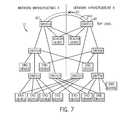
- FIG. 7 is a figure similar to that of FIG. 6 showing an interconnection failure between backbone switches
- FIG. 8 is a figure similar to that of FIG. 7 showing a local failure affecting a beacon
- FIG. 9 is a figure similar to that of FIG. 8 showing failure of a beacon.
- FIG. 10 is a figure similar to that of FIG. 9 showing multiple faults
- FIG. 11 is flowchart showing operation of the network card of FIG. 2 under fault condition as is implemented in hardware of the communication circuit in the preferred embodiment and;
- FIG. 12 shows a fragmentary view similar to that of FIG. 10 of an extension of the present invention to provide multiple redundancy.
- an industrial control system 10 may include a number of end devices 12 a - 12 e , each having two connections 14 a and 14 b via an Ethernet interface circuit 20 (not shown in FIG. 1 ) communicating respectively with different switches 16 a and 16 b through independent network media 18 .
- the switches 16 , the network media 18 , and the Ethernet interface circuits 20 provide a fault-tolerant network 11 , as will be described below.
- the end devices 12 a - 12 e may be any industrial control device such as a programmable logic controller (end device 12 a ), a human machine interface (end device 12 b ), a standard personal computer (end device 12 c ), a motor controller (end device 12 d ), and an input/output rack (end device 12 e ).
- a programmable logic controller end device 12 a
- a human machine interface end device 12 b
- end device 12 c a standard personal computer
- end device 12 d motor controller
- end device 12 e input/output rack
- Each of the switches 16 a and 16 b may be standard Ethernet switches of a type known in the art. To the extent that the switches 16 may have IGMP snooping and filtering of Ethernet multicast addresses, this feature may be preferably deactivated to allow these switches to work more rapidly with the present invention. To the extent that the switches 16 may have “learning” and filtering of Ethernet unicast addresses, preferably, switches may provide for a configurable aging mechanism for learned addresses, however, this is not required.
- the network media 18 may be, for example, electrical cable, optical fiber or wireless transmitter/receiver pairs, or the like.
- each of the end devices 12 may include an Ethernet interface circuit 20 providing the two connections 14 a and 14 b to the rest of the network 11 .
- the connections 14 a and 14 b are realized through two standard physical ports 22 a and 22 b accepting respectively connectors 24 a and 24 b attached to network media 18 .
- the physical ports 22 a and 22 b are connected to a hardware switching circuit 26 , such as may be implemented, for example, using a field programmable gate array (FPGA) and/or an application-specific integrated circuit (ASIC), that provides a communication between one or the other of the ports 22 a and 22 b with a host microprocessor 28 .
- the switching circuit 26 may include a multi-line port selector 32 switching data flow from either port 22 a or port 22 b , depending on the state of the port selector 32 , to a host microprocessor 28 .
- a logic circuit 34 being part of the switching circuit 26 controls the port selector 32 according to state machine that generally detects faults and switches between the ports 22 a and 22 b .
- port selector 32 enables only one port 22 a and disables the other port 22 b or vice versa. All communication flows only through the enabled port 22 .
- the host microprocessor 28 typically executes a program implementing specific features of the end device 12 .
- the host microprocessor 28 holds a single media-access control layer (MAC) network address 30 that is used by a single activated one of the ports 22 a and 22 b as a network address when they are alternatively enabled.
- MAC media-access control layer
- the host microprocessor 28 authorizes the logic circuit 34 to switch between the ports 22 a and 22 b after the logic circuit 34 provides an interrupt to the host microprocessor 28 when a fault or other significant network event has occurred.
- the switching authorization by the host microprocessor 28 requires the execution of very little code so that the host microprocessor 28 may reconfigure the ports with a delay of less than 10 microseconds. During this short switching time, some packets will be lost but higher-level network protocols will function correctly to handle these lost packets just like packets lost due to other network errors. It is unlikely that duplicate packets will be received during this delay period, but if a few duplicate packets are received, they will be detected by higher-level network protocols.
- the logic circuit 34 may directly detect faults by two means depending on whether the fault is “local” to the Ethernet interface circuit 20 or “remote”, that is, separated from the Ethernet interface circuit 20 by at least one switch 16 .
- the logic circuit 34 preferably includes a beacon generator/detector 35 either providing a means for receiving beacon packets simultaneously on both of ports 22 a and 22 b (as will be described) or transmitting beacon packet when so configured, on a single activated one of ports 22 a and 22 b . In this mode, beacon packets will be detected at both of the ports 22 a and 22 b regardless of which one is active for data transfer.
- beacon generator/detector 35 detects failure of any beacon packet to arrive within a predefined timeout period at the active one of ports 22 a or 22 b , from a remote beacon in the network, the particular port failing to detect the beacon packet is declared to be in fault mode.
- the logic circuit 34 interrupts the host microprocessor 28 , and the host microprocessor 28 instructs the logic circuit 34 to switch to the other port 22 (assuming it has not previously faulted).
- a faulted port 22 becomes enabled again, it may be restored by the host microprocessor 28 upon interruption by the logic circuit 34 . Correct location of one or more beacons thus allows each Ethernet interface circuit 20 to detect remote faults removed from the given communication circuit 20 and the switch 16 to which it connects directly.
- the logic circuit 34 may also detect “local” faults, between the Ethernet interface circuit 20 and the closest switch 16 using the mechanisms of IEEE 802.3 standard. These faults are communicated to the host microprocessor 28 like the “remote” faults and treated in a like manner to trigger a change of ports 22 a and 22 b.
- beacon generator/detector 35 When the beacon generator/detector 35 is configured as a generator it provides a transmission of a beacon packet at a regular interval to aid in the detection of remote faults as described above.
- the beacon packets are transmitted at highest priority on the network using IEEE 802.3 priority tagged frames, which the switches 16 are configured to support.
- the generator/detector 35 combines these two functions of beacon packet generation and beacon packet detection for efficiency, however, it will be recognized from the following description that the beacon generation function can be performed by a separate device.
- the switching circuit 26 communicates with the host microprocessor 28 and the ports 22 a and 22 b using IEEE 802.3 medium independent interface (MII) bus.
- MII medium independent interface
- the address and data buses of the host microprocessor 28 allows configuration of the logic circuit 34 by the host microprocessor 28 using memory-mapped registers and may provide for the transmission of interrupt signals.
- the switching circuit 26 may also provide for multi-cast address filtering so that the host microprocessor 28 is not inundated with multi-cast traffic resulting from the disabling of IGMP snooping and filtering in the switches 16 .
- the present invention may work with any network topology providing at least some redundancy, ideally the network is set up for symmetrical redundancy or asymmetrical redundancy with non-overlapping sub-trees, where each end device 12 has one of its connections 14 a and 14 b connected directly to switches 16 in different ones of two network infrastructure: (1) Network Infrastructure A and (2) Network Infrastructure B.
- Multiple layers of switches 16 may be employed in each network infrastructure with all connections in each network infrastructure leading to one or the other of two switches 16 ′ and 16 ′′ forming a network infrastructure top-level 40 .
- Top-level switches 16 ′ and 16 ′′ communicate directly with each other over a backbone 42 incorporating two or more links providing link aggregation capability per IEEE 802.3 Part III “Carrier sense multiple access with collision detection (CSMA/CD) Access Method and Physical Layer Specifications, 2002”. With link aggregation capability, traffic is shared among the links between the two top-level switches 16 ′ and 16 ′′ so that failure of one line of the backbone 42 will not prevent such communication. With such an arrangement, network infrastructure A and network infrastructure B form a single logical network.
- the network 11 so described, provides redundant connections between each end device 12 and switches 16 in both of the Network Infrastructure A and Network Infrastructure B, and ensures highly reliable connections between Network Infrastructure A Network Infrastructure B through the top-level switches 16 ′ and 16 ′′.
- the exact number and level of switches 16 will be dependent on the application requirement.
- the invention contemplates that extremely large networks may be constructed. For example, with three levels of switches, using eight local links plus one uplink per switch, a network can be constructed with greater than five hundred nodes and with 24 local links plus one uplink per switch, more than 10,000 nodes.
- two end devices 12 ′ are designated solely to provide for beacon packets (via the beacon generator/detector 35 ) and the remaining end devices 12 are configured to detect the beacon packets so transmitted.
- the two end devices 12 ′ transmitting beacon packets transmit these packets out of one of their connections 14 a and 14 b preferably so that one set of beacon packets from one end device 12 ′ goes directly to top-level switch 16 ′ and the other set of beacon packets from the other end device 12 ′ goes directly to top-level switch 16 ′′.
- the beacon end devices 12 ′ broadcast a short beacon packet on the network periodically.
- the periodicity of the beacon packet transmission is determined by a worst-case delay for the beacon packet to travel from a beacon end device 12 ′ to the farthest end device 12 for the specific network 11 .
- This periodicity is programmed into each Ethernet interface circuit 20 so that a timeout measurement may be used by the beacon detectors to determine that the beacon packets have been lost and to declare a fault on the ports 22 a or 22 b .
- the time out period is slightly more than twice the worst-case delay to guard against false triggering.
- the beacon period may be 450 microseconds and the timeout period 950 microseconds, slightly more than two beacon periods.
- a single “local” fault 60 may occur between an end device 12 and the switch 16 to which it is connected on Network Infrastructure A. This failure may be either in the media 18 , forming the connection between device 12 and the switch 16 , the connectors connecting the media 18 to the switch 16 or end device 12 or individual physical layer electrical interfaces of the switch 16 or end device 12 . In this example, it will be assumed that end device 12 connects through connection 14 a and port 22 a (the first port) to the switch 16 .
- this fault 60 is detected by the logic circuit 34 as indicated at decision block 50 using standard IEEE 802.3 mechanisms that detect such local connection failures.
- detection of the fault 60 causes the Ethernet interface circuit 20 to send an interrupt (indicated by process block 52 ) to the host microprocessor 28 .
- the logic circuit 34 determines whether the other port 22 b is also faulted (meaning that there is a fault somewhere between it and both of the top-level switches) reflected in a failure to receive beacon packets from either beacon or a local fault. If so, a failure is reported at process block 55 and the network has failed under a double fault condition.
- the logic circuit 34 will determine at decision block 54 that the other port 22 b has not faulted and the Ethernet interface circuit 20 will switch to port 22 b as indicated by process block 56 while disabling port 22 a .
- the Ethernet interface circuit 20 sends out a short broadcast message that allows for learning by intervening switches.
- connection 14 b the end device 12
- port 22 a the network continues to operate with the end device 12 , however, communicating through connection 14 b and port 22 b .
- connection 14 b the end device 12
- port 22 a the network continues to operate with the end device 12 , however, communicating through connection 14 b and port 22 b .
- port 22 a may have its fault corrected, communication through port 22 a may be resumed.
- fault 60 may be located between switch 16 and top-level switch 16 ′, the former switch 16 serving a number of end devices, 12 a - 12 c .
- each of these devices, 12 a - 12 c communicates with the network 11 via its connection 14 a and port 22 a at the time of the fault.
- the end devices 12 a - 12 c cannot directly detect failure per decision block 50 but must deduce a remote failure from the missing beacon packets normally passing through switch 16 per decision block 62 when no beacon packet is received within predefined timeout period.
- the logic circuit 34 proceeds to process block 64 and an interrupt is sent to the host microprocessor 28 causing again the ports to switch from port 22 a - 22 b per process blocks 54 , 56 , and 58 for each of the end devices 12 a through 12 c.
- a fault on a switch 16 connected directly to end devices 12 a , 12 b and 12 c internal to the switch may not be detectable as a local fault per decision block 50 through IEEE 802.3 standard mechanisms, however, it will be detected by loss of the beacon packets as described above per decision block 62 .
- the logic circuit 34 proceeds to process block 64 and an interrupt is sent to the host microprocessor 28 causing again the ports to switch from port 22 a - 22 b per process blocks 54 , 56 , and 58 for each of the end devices 12 a through 12 c . It should be noted that if the fault were to occur on a top-level switch 16 ′ or 16 ′′ all of the end devices 12 would switch over to Network Infrastructure B and the system would continue to operate.
- a fault 60 may occur on the network backbone 42 .
- Such a fault is handled by the link aggregation procedure described above being a standard portion of the IEEE 802.3.
- a single fault may occur between a beacon end device 12 ′ and a top-level switch 16 ′′ of the backbone. Because the fault is on the immediate link to the beacon end device 12 ′ and the top-level switch 16 ′′, the beacon end device 12 ′ will detect it immediately per decision block 50 and begin transmitting to switch 16 ′. The switch 16 ′ will relay beacon signals through switch 16 ′′ to Network Infrastructure A.
- beacon end device 12 ′ communicating with switch 16 ′′ may itself fail. Because the other beacon end device 12 ′ is still active, however, the system will continue to operate without any problems with beacon pulses being transmitted, for example, from beacon end device 12 ′ to switch 16 ′ then to switch 16 ′′ for distribution over the Network Infrastructure A.
- the present invention can handle all single faults and all combinations of multiple single faults with 60 a - 60 f as shown being one such combination.
- FIG. 12 the present invention has been described for clarity with respect to two Network Infrastructures A and B, however, as will be understood from the above description, the invention can be readily expanded to an arbitrary number of networks infrastructures, for example, a Network Infrastructure A, B and C having top-level switches 16 ′, 16 ′′ and 16 ′′′ and three beacon end devices 12 ′ associated with each infrastructure division. Again this network 11 ′ is a single network with each end device 12 (not shown) having a unique address on the network. With three network infrastructures, all single faults, all double faults and all combinations of multiple single and double faults can be tolerated.
- Unicast packets are affected by learning and filtering features that may be incorporated into the switches 16 .
- switches 16 After a reconfiguration (i.e., switching from ports 22 a to 22 b ), switches 16 will have invalid knowledge. Nevertheless, a switch 16 , implementing learning correctly, will update its database when a packet with a learned MAC address in a source field is received on a different port from the learned port stored in the database. For this reason, as noted above, when an end device 12 reconfigures its ports, it sends out a short broadcast message per process block 58 of FIG. 11 . This broadcast packet is of no interest to other end devices and will be dropped.
- Some switches 16 also provide configurable aging mechanisms for learned addresses. This feature may also be used as a fallback mechanism to facilitate rapid reconfiguration.
Abstract
Fault-tolerant Ethernet is provided through the use of special interfaces providing duplicate ports that may be alternatively enabled with the same network address. A switching between the ports, corrects for single faults in a two-way redundant system without time-consuming reconfiguration of other end devices or the need for complex middleware in the end devices.
Description
- This application is a continuation of U.S. patent application Ser. No. 11/520,192, filed on Sep. 13, 2006.
- This invention relates generally to fault-tolerant electronic communication networks, and, in particular, to a fault-tolerant network that operates rapidly to correct faults occurring when network components fail and which is suitable for real-time industrial control.
- Industrial controllers are special-purpose computers that provide for real-time, highly reliable control of manufacturing equipment and machines and processes. Typically, an industrial controller executes a stored program to read inputs from the machine or process through sensors connected to the industrial controller through a set of input/output (I/O) circuits. Based on those inputs, the industrial controller generates output signals that control the machine or process through actuators or the like.
- Often, the components of the industrial control system will be distributed throughout a factory and will therefore communicate over a specialized communication network that provides for high-speed operation (to allow real time control) with specialized protocols to ensure that data is reliably and predictably transmitted.
- Desirably, the components of an industrial control system might be interconnected using common network components, for example, commonly available Ethernet network components. Such an ability could cut the costs of establishing and maintaining the network and in some cases would allow the use of existing network infrastructures. In addition, the ability to use a common network, such as Ethernet, could facilitate communication with devices outside of the industrial control system or that are not directly involved in the control process.
- One obstacle to the adoption of Ethernet and similar standard networks is that they are not fault-tolerant, that is, failure in as little as one network component can cause the network to fail—an unacceptable probability for an industrial control system where reliability is critical.
- The prior art provides several methods to increase the fault tolerance of Ethernet and similar networks. A first approach is to use a ring topology where each end device (node) is connected to the other nodes with a ring of interconnected components (such as switches) and communication media. The operation of the ring network is controlled by a ring manager device with special software. Failure of one component or media segment in the ring still provides a second path between every node. This second path is blocked by ring manager device in normal mode of operation. Upon detecting a network failure, the ring manager device will reconfigure the network to use second path. Such systems provide for a correction of a network failure on the order of 100 microseconds to 500 milliseconds. A drawback is that multiple faults (e.g. the failure of two segments of media) cannot be accommodated.
- A second approach equips each node with software “middleware” that controls the connection of the node to one of two or more different networks. In the event of component or media failure, the middleware changes the local network interface to transmit and receive messages on the back-up network using a new Ethernet address. The middleware communicates with the middleware at other nodes to update this changed address. This approach can tolerate multiple faults, but the time necessary to reconfigure the network can be as much as 30 seconds. An additional problem with this latter approach is that multiple networks are needed (one for primary use and one for backup) which can be difficult to maintain, inevitably having differences in configuration and performance.
- In a third approach, a single network with two or more redundant network infrastructures is used and each device is provided with multiple ports, and each port is connected to a redundant infrastructure of that network. The middleware in each device is provided with alternate paths through multiple infrastructures to all other devices in the network. The middleware in each device sends diagnostic messages on each alternate path periodically and exchanges status information for each path with middleware in all other devices continuously. When an application level message needs to be sent, the middleware in source device will pick a functioning path to target device based on current path status information. In the event of a network failure on a path, the middleware in a device will detect it either through non-reception of diagnostic messages from the other device on that path or through path status information received from the other device through an alternate path. Upon detecting path failure the status information for that path will be updated and that path will not be used for future transmissions. Such detection and reconfiguration may occur typically in less than one second.
- This need to reconfigure each node when there is a network failure fundamentally limits the speed with which network failures may be corrected, both because of the need for complex software (middleware) to detect the failure and coordinate address or path status changes, and because of the time required for communication with other nodes on the network.
- The present invention largely eliminates the need to reconfigure other end nodes by providing each end node with two network connections both having the same network address. One or the other network connection is activated by hardware in a network card in response to a detected failure. This hardware switching and the elimination of the need for address changes provide for failure detection and reconfiguration speeds of less than 1 millisecond even for very large networks.
- Network failures may be detected using standard mechanisms of IEEE 802.3, for local failures, and by using special beacons positioned on the network so that a loss of beacon packets indicates a remote network failure. Both types of failure may be readily detected in hardware.
- The single network to which the nodes are connected is configured so that there are multiple paths between each node. Preferably this is done by providing at least two backbone switches interconnected by a high reliability connection, and connecting each end node directly or indirectly to both switches.
- Specifically, the present invention provides a system for creating a fault-tolerant Ethernet network of end devices, each end device connected by network switches and network media. The system includes Ethernet communications circuits associated with each end device and communicating between the host microprocessor of the end device and at least two ports having a common Ethernet address and connectable to different network media. The communication circuit switches the end device to a second of the ports upon occurrence of a fault affecting a first of the ports.
- Thus, it is one object of at least one embodiment of the invention to provide for extremely fast fault correction that does not require reconfiguration of node addresses and that may be accomplished primarily with high-speed hardware.
- The Ethernet communication circuit may detect a fault affecting the first of the ports by detecting a failure of Ethernet communication with a network switch communicating to the first port.
- Thus, it is an object of at least one embodiment of the invention to provide for simple local fault detection using the mechanisms provided in IEEE 802.3 standard.
- The system may include one or more beacons transmitting beacon packets over the network media to both the first and second ports and the Ethernet communication circuit may detect a fault affecting the first or second port by detecting non-reception of any beacon packet within a predefined timeout period at the respective port.
- Thus, it is an object of at least one embodiment of the invention to provide for a comprehensive detection of faults remote from a given end device.
- The beacon packet may be retransmitted at a periodic rate and the said predefined timeout period may typically be deduced as slightly more than twice the periodic rate.
- It is thus an object of at least one embodiment of the invention to provide for extremely fast fault detection limited only by the speed of propagation of signals in the network yet to eliminate false fault detection.
- The Ethernet communication circuit may incorporate a beacon which may be selectively actuable by a user to transmit a beacon packet over the network media to other Ethernet communications circuits.
- Thus, it is another object of at least one embodiment of the invention to provide for a fault-tolerant system that may be implemented with a single specialized circuit card and in all other respects may employ standard Ethernet hardware.
- The beacons may transmit at the highest priority under IEEE 802.3.
- Thus, it is an object of at least one embodiment of the invention to enlist the priority structure of Ethernet to ensure extremely fast detection of faults.
- The Ethernet communication circuits may broadcast a packet to other Ethernet communications circuits when the communications circuit switches between ports to promote learning by intermediary switches that use a learning protocol.
- Thus, it is an object of at least one embodiment of the invention to allow intermediary switches and the like to relearn the appropriate routing for signals in the event of a fault.
- The Ethernet communication circuits may employ dedicated circuitry to switch between ports.
- Thus, it is an object of at least one embodiment of the invention to eliminate the need for complex software middleware, thus, to provide improved speed of switching.
- The Ethernet communication circuit may be used on a network having at least two switches that are designated top-level switches and communicate with each other via a fault-tolerant backbone. Each end device may communicate directly or indirectly with the first of the top-level switches via one port and with the second of the top-level switches via a second port.
- Thus, it is an object of at least one embodiment of the invention to provide a simple topology in a single network that allows fault tolerance.
- The top-level switches may provide for IEEE 802.3 link aggregation capability.
- Thus it is an object of at least one embodiment of the invention to provide for a reliable logical redundancy in a single network using standard Ethernet protocols and hardware.
- These particular objects and advantages may apply to only some embodiments falling within the claims and thus do not define the scope of the invention.
-
FIG. 1 is a block diagram of an industrial control system having controller and other end devices connected as nodes on an Ethernet network, each node communicating with multiple Ethernet switches; -
FIG. 2 is a block diagram of a communication circuit employed by the end nodes ofFIG. 1 providing two ports using the same address to connect to the multiple switches and showing circuitry for switching between the two ports; -
FIG. 3 is a diagram of an Ethernet network configured for use with the present invention connecting multiple end devices redundantly to each of two different backbone switches at a top-level. -
FIG. 4 is a figure similar to that ofFIG. 3 showing a single local fault on the network; -
FIG. 5 is a figure similar to that ofFIG. 4 showing a single remote fault on the network; -
FIG. 6 is a figure similar to that ofFIG. 5 showing switch failure; -
FIG. 7 is a figure similar to that ofFIG. 6 showing an interconnection failure between backbone switches; -
FIG. 8 is a figure similar to that ofFIG. 7 showing a local failure affecting a beacon; -
FIG. 9 is a figure similar to that ofFIG. 8 showing failure of a beacon. -
FIG. 10 is a figure similar to that ofFIG. 9 showing multiple faults; -
FIG. 11 is flowchart showing operation of the network card ofFIG. 2 under fault condition as is implemented in hardware of the communication circuit in the preferred embodiment and; -
FIG. 12 shows a fragmentary view similar to that ofFIG. 10 of an extension of the present invention to provide multiple redundancy. - Referring now to
FIG. 1 , anindustrial control system 10 may include a number ofend devices 12 a-12 e, each having twoconnections FIG. 1 ) communicating respectively withdifferent switches independent network media 18. - Together, the
switches 16, thenetwork media 18, and theEthernet interface circuits 20 provide a fault-tolerant network 11, as will be described below. - The
end devices 12 a-12 e may be any industrial control device such as a programmable logic controller (end device 12 a), a human machine interface (end device 12 b), a standard personal computer (end device 12 c), a motor controller (end device 12 d), and an input/output rack (end device 12 e). - Each of the
switches switches 16 may have IGMP snooping and filtering of Ethernet multicast addresses, this feature may be preferably deactivated to allow these switches to work more rapidly with the present invention. To the extent that theswitches 16 may have “learning” and filtering of Ethernet unicast addresses, preferably, switches may provide for a configurable aging mechanism for learned addresses, however, this is not required. - The
network media 18 may be, for example, electrical cable, optical fiber or wireless transmitter/receiver pairs, or the like. - Referring now to
FIG. 2 , as mentioned above, each of theend devices 12 may include anEthernet interface circuit 20 providing the twoconnections network 11. Theconnections physical ports connectors media 18. - The
physical ports hardware switching circuit 26, such as may be implemented, for example, using a field programmable gate array (FPGA) and/or an application-specific integrated circuit (ASIC), that provides a communication between one or the other of theports host microprocessor 28. In this regard, the switchingcircuit 26 may include amulti-line port selector 32 switching data flow from eitherport 22 a orport 22 b, depending on the state of theport selector 32, to ahost microprocessor 28. Alogic circuit 34 being part of the switchingcircuit 26 controls theport selector 32 according to state machine that generally detects faults and switches between theports port selector 32 enables only oneport 22 a and disables theother port 22 b or vice versa. All communication flows only through the enabled port 22. - The
host microprocessor 28 typically executes a program implementing specific features of theend device 12. Importantly, thehost microprocessor 28 holds a single media-access control layer (MAC)network address 30 that is used by a single activated one of theports - In the preferred embodiment, the
host microprocessor 28 authorizes thelogic circuit 34 to switch between theports logic circuit 34 provides an interrupt to thehost microprocessor 28 when a fault or other significant network event has occurred. The switching authorization by thehost microprocessor 28 requires the execution of very little code so that thehost microprocessor 28 may reconfigure the ports with a delay of less than 10 microseconds. During this short switching time, some packets will be lost but higher-level network protocols will function correctly to handle these lost packets just like packets lost due to other network errors. It is unlikely that duplicate packets will be received during this delay period, but if a few duplicate packets are received, they will be detected by higher-level network protocols. - Referring still to
FIG. 2 , thelogic circuit 34 may directly detect faults by two means depending on whether the fault is “local” to theEthernet interface circuit 20 or “remote”, that is, separated from theEthernet interface circuit 20 by at least oneswitch 16. - For detecting “remote” faults, the
logic circuit 34 preferably includes a beacon generator/detector 35 either providing a means for receiving beacon packets simultaneously on both ofports ports ports - Generally, when the beacon generator/
detector 35 detects failure of any beacon packet to arrive within a predefined timeout period at the active one ofports logic circuit 34 interrupts thehost microprocessor 28, and thehost microprocessor 28 instructs thelogic circuit 34 to switch to the other port 22 (assuming it has not previously faulted). Similarly, when a faulted port 22 becomes enabled again, it may be restored by thehost microprocessor 28 upon interruption by thelogic circuit 34. Correct location of one or more beacons thus allows eachEthernet interface circuit 20 to detect remote faults removed from the givencommunication circuit 20 and theswitch 16 to which it connects directly. - The
logic circuit 34 may also detect “local” faults, between theEthernet interface circuit 20 and theclosest switch 16 using the mechanisms of IEEE 802.3 standard. These faults are communicated to thehost microprocessor 28 like the “remote” faults and treated in a like manner to trigger a change ofports - When the beacon generator/
detector 35 is configured as a generator it provides a transmission of a beacon packet at a regular interval to aid in the detection of remote faults as described above. The beacon packets are transmitted at highest priority on the network using IEEE 802.3 priority tagged frames, which theswitches 16 are configured to support. - In the preferred embodiment, the generator/
detector 35 combines these two functions of beacon packet generation and beacon packet detection for efficiency, however, it will be recognized from the following description that the beacon generation function can be performed by a separate device. In the preferred embodiment, the switchingcircuit 26 communicates with thehost microprocessor 28 and theports host microprocessor 28 allows configuration of thelogic circuit 34 by thehost microprocessor 28 using memory-mapped registers and may provide for the transmission of interrupt signals. The switchingcircuit 26 may also provide for multi-cast address filtering so that thehost microprocessor 28 is not inundated with multi-cast traffic resulting from the disabling of IGMP snooping and filtering in theswitches 16. - Referring now to
FIG. 3 , although the present invention may work with any network topology providing at least some redundancy, ideally the network is set up for symmetrical redundancy or asymmetrical redundancy with non-overlapping sub-trees, where eachend device 12 has one of itsconnections switches 16 in different ones of two network infrastructure: (1) Network Infrastructure A and (2) Network Infrastructure B. Multiple layers ofswitches 16 may be employed in each network infrastructure with all connections in each network infrastructure leading to one or the other of twoswitches 16′ and 16″ forming a network infrastructure top-level 40. Top-level switches 16′ and 16″ communicate directly with each other over abackbone 42 incorporating two or more links providing link aggregation capability per IEEE 802.3 Part III “Carrier sense multiple access with collision detection (CSMA/CD) Access Method and Physical Layer Specifications, 2002”. With link aggregation capability, traffic is shared among the links between the two top-level switches 16′ and 16″ so that failure of one line of thebackbone 42 will not prevent such communication. With such an arrangement, network infrastructure A and network infrastructure B form a single logical network. - The
network 11 so described, provides redundant connections between eachend device 12 and switches 16 in both of the Network Infrastructure A and Network Infrastructure B, and ensures highly reliable connections between Network Infrastructure A Network Infrastructure B through the top-level switches 16′ and 16″. Generally the exact number and level ofswitches 16 will be dependent on the application requirement. The invention contemplates that extremely large networks may be constructed. For example, with three levels of switches, using eight local links plus one uplink per switch, a network can be constructed with greater than five hundred nodes and with 24 local links plus one uplink per switch, more than 10,000 nodes. - In the preferred embodiment, two
end devices 12′ are designated solely to provide for beacon packets (via the beacon generator/detector 35) and the remainingend devices 12 are configured to detect the beacon packets so transmitted. The twoend devices 12′ transmitting beacon packets transmit these packets out of one of theirconnections end device 12′ goes directly to top-level switch 16′ and the other set of beacon packets from theother end device 12′ goes directly to top-level switch 16″. - As described above, the
beacon end devices 12′ broadcast a short beacon packet on the network periodically. The periodicity of the beacon packet transmission is determined by a worst-case delay for the beacon packet to travel from abeacon end device 12′ to thefarthest end device 12 for thespecific network 11. This periodicity is programmed into eachEthernet interface circuit 20 so that a timeout measurement may be used by the beacon detectors to determine that the beacon packets have been lost and to declare a fault on theports - Referring now to
FIGS. 2 , 4 and 11, a single “local”fault 60 may occur between anend device 12 and theswitch 16 to which it is connected on Network Infrastructure A. This failure may be either in themedia 18, forming the connection betweendevice 12 and theswitch 16, the connectors connecting themedia 18 to theswitch 16 orend device 12 or individual physical layer electrical interfaces of theswitch 16 orend device 12. In this example, it will be assumed thatend device 12 connects throughconnection 14 a andport 22 a (the first port) to theswitch 16. - As shown in
FIG. 11 , thisfault 60 is detected by thelogic circuit 34 as indicated atdecision block 50 using standard IEEE 802.3 mechanisms that detect such local connection failures. As indicated byprocess block 52, detection of thefault 60 causes theEthernet interface circuit 20 to send an interrupt (indicated by process block 52) to thehost microprocessor 28. Atdecision block 54, thelogic circuit 34 determines whether theother port 22 b is also faulted (meaning that there is a fault somewhere between it and both of the top-level switches) reflected in a failure to receive beacon packets from either beacon or a local fault. If so, a failure is reported atprocess block 55 and the network has failed under a double fault condition. - More typically, however, the
logic circuit 34 will determine atdecision block 54 that theother port 22 b has not faulted and theEthernet interface circuit 20 will switch toport 22 b as indicated byprocess block 56 while disablingport 22 a. At succeedingprocess block 58, theEthernet interface circuit 20 sends out a short broadcast message that allows for learning by intervening switches. - At this point, the network continues to operate with the
end device 12, however, communicating throughconnection 14 b andport 22 b. As discussed above, should port 22 a have its fault corrected, communication throughport 22 a may be resumed. - Referring now to
FIGS. 2 , 5 and 11, in a second case,fault 60 may be located betweenswitch 16 and top-level switch 16′, theformer switch 16 serving a number of end devices, 12 a-12 c. As before, it will be assumed that each of these devices, 12 a-12 c, communicates with thenetwork 11 via itsconnection 14 a andport 22 a at the time of the fault. With this fault, theend devices 12 a-12 c cannot directly detect failure perdecision block 50 but must deduce a remote failure from the missing beacon packets normally passing throughswitch 16 perdecision block 62 when no beacon packet is received within predefined timeout period. When such a remote fault is detected, thelogic circuit 34 proceeds to processblock 64 and an interrupt is sent to thehost microprocessor 28 causing again the ports to switch from port 22 a-22 b per process blocks 54, 56, and 58 for each of theend devices 12 a through 12 c. - Referring now to
FIGS. 2 , 6 and 11, a fault on aswitch 16 connected directly to enddevices decision block 50 through IEEE 802.3 standard mechanisms, however, it will be detected by loss of the beacon packets as described above perdecision block 62. Thelogic circuit 34 proceeds to processblock 64 and an interrupt is sent to thehost microprocessor 28 causing again the ports to switch from port 22 a-22 b per process blocks 54, 56, and 58 for each of theend devices 12 a through 12 c. It should be noted that if the fault were to occur on a top-level switch 16′ or 16″ all of theend devices 12 would switch over to Network Infrastructure B and the system would continue to operate. - Referring now to
FIGS. 2 , 7, and 11, afault 60 may occur on thenetwork backbone 42. Such a fault is handled by the link aggregation procedure described above being a standard portion of the IEEE 802.3. - Referring now to
FIGS. 2 , 8 and 11, a single fault may occur between abeacon end device 12′ and a top-level switch 16″ of the backbone. Because the fault is on the immediate link to thebeacon end device 12′ and the top-level switch 16″, thebeacon end device 12′ will detect it immediately perdecision block 50 and begin transmitting to switch 16′. Theswitch 16′ will relay beacon signals throughswitch 16″ to Network Infrastructure A. - Finally, as shown in
FIGS. 2 , 9 and 11,beacon end device 12′ communicating withswitch 16″ may itself fail. Because the otherbeacon end device 12′ is still active, however, the system will continue to operate without any problems with beacon pulses being transmitted, for example, frombeacon end device 12′ to switch 16′ then to switch 16″ for distribution over the Network Infrastructure A. - Referring to
FIGS. 2 , 10 and 11, it will be understood from the above description that the present invention can handle all single faults and all combinations of multiple single faults with 60 a-60 f as shown being one such combination. - Referring now to
FIG. 12 , the present invention has been described for clarity with respect to two Network Infrastructures A and B, however, as will be understood from the above description, the invention can be readily expanded to an arbitrary number of networks infrastructures, for example, a Network Infrastructure A, B and C having top-level switches 16′, 16″ and 16′″ and threebeacon end devices 12′ associated with each infrastructure division. Again thisnetwork 11′ is a single network with each end device 12 (not shown) having a unique address on the network. With three network infrastructures, all single faults, all double faults and all combinations of multiple single and double faults can be tolerated. - It would be understood from this description, that forwarding of multicast packets in
switches 16 could be affected by IGMP snooping and filtering. Accordingly, if IGMP snooping and filtering is turned on, theswitches 16 in the system will have invalid knowledge after reconfiguration of an enddevice changing port switches 16. - Unicast packets are affected by learning and filtering features that may be incorporated into the
switches 16. After a reconfiguration (i.e., switching fromports 22 a to 22 b), switches 16 will have invalid knowledge. Nevertheless, aswitch 16, implementing learning correctly, will update its database when a packet with a learned MAC address in a source field is received on a different port from the learned port stored in the database. For this reason, as noted above, when anend device 12 reconfigures its ports, it sends out a short broadcast message perprocess block 58 ofFIG. 11 . This broadcast packet is of no interest to other end devices and will be dropped. - Some
switches 16 also provide configurable aging mechanisms for learned addresses. This feature may also be used as a fallback mechanism to facilitate rapid reconfiguration. - It is specifically intended that the present invention not be limited to the embodiments and illustrations contained herein, but include modified forms of those embodiments including portions of the embodiments and combinations of elements of different embodiments as come within the scope of the following claims.
Claims (18)
1. A fault-tolerant device configured to communicate on an Ethernet network, comprising:
a processor;
at least two ports connectable to the Ethernet network, each port using a common Media Access Control (MAC) address; and
an Ethernet interface circuit further comprising a port selection circuit to selectively connect one of the ports between the processor and the Ethernet network for transmitting data and an error detection circuit connected to each of the ports to concurrently detect a fault on the Ethernet network with either of the ports regardless of which of the ports is enabled by the port selection circuit, wherein the port selection circuit initially connects a first of the ports and switchably connects the second of the ports upon detection of a fault affecting the first of the ports without remapping the MAC address.
2. The device of claim 1 wherein the Ethernet interface circuit detects a fault affecting the first of the ports both by detecting a local failure of Ethernet communication with a first network switch directly connected to the first port and by detecting a remote failure of Ethernet communication with a second network switch not directly connected to the first port.
3. The device of claim 1 wherein the error detection circuit is configured to receive a beacon packet over each of the ports and wherein the error detection circuit identifies a fault affecting one of the ports if no beacon packets are received within a predefined timeout period at the port.
4. The device of claim 3 wherein the beacon packets are retransmitted at a periodic rate and the predefined timeout period is deduced from the periodic rate.
5. The device of claim 3 wherein the Ethernet interface circuit is configured to selectively transmit a beacon packet over the Ethernet network.
6. The device of claim 3 wherein the beacon packets are transmitted at the highest priority under IEEE 802.3.
7. The device of claim 1 wherein the Ethernet interface circuit broadcasts a packet over the Ethernet network when the port selection circuit switches between the first and the second of the ports.
8. A fault-tolerant Ethernet network, comprising at least two end devices, each end device configured to communicate to another end device via at least two network connections established using network switches and network media, wherein each end device further comprises:
a processor;
at least two ports, each port establishing one of the network connections to a different network switch via different network media, wherein each port uses a common Media Access Control (MAC) address; and
an Ethernet interface circuit further comprising a port selection circuit to selectively connect one of the at least two ports between the processor and the Ethernet network for transmitting data, and an error detection circuit connected to both ports to concurrently detect a fault on the Ethernet network with either port regardless of which port is enabled by the port selection circuit, wherein the port selection circuit initially connects a first of the ports and switchably connects the second of the ports upon detection of a fault affecting the first of the ports without remapping the MAC address;
wherein at least two of the switches are designated top-level switches and are connected to each other via a redundant network connection having two or more links between the top-level switches; and
wherein each end device is connected directly or indirectly with a first of the top-level switches via a first of the ports and with a second of the top-level switches via a second of the ports.
9. The fault-tolerant Ethernet network of claim 8 wherein the top-level switches provide IEEE 802.3 link aggregation capability.
10. The fault-tolerant Ethernet network of claim 8 further including at least two beacons transmitting a beacon packet over the network media; each beacon connected directly to one of the top-level switches; wherein a fault is detected by an absence of any of the beacon packets within a predefined timeout period at one of the ports.
11. The fault-tolerant Ethernet network of claim 10 wherein each beacon connects to multiple top-level switches.
12. The fault-tolerant Ethernet network of claim 10 wherein the beacon packet is retransmitted at a periodic rate having a period greater than a greatest time required for the beacon packet to propagate between the beacons and the end devices farthest from them on the network.
13. The fault-tolerant Ethernet network of claim 10 wherein the Ethernet interface circuit also includes a beacon selectively actuated by a user to transmit a beacon packet over the network media to other Ethernet interface circuits.
14. The fault-tolerant Ethernet network of claim 10 wherein beacons transmit at the highest priority under IEEE 802.3.
16. The fault-tolerant Ethernet network of claim 8 wherein the Ethernet interface circuits broadcast a packet to other Ethernet interface circuits when the port selection circuit switches between ports.
17. The fault-tolerant Ethernet network of claim 8 wherein the Ethernet interface circuits includes a hardware circuit switching between ports.
18. A method of detecting a fault on a fault-tolerant network comprising the steps of:
providing at least one end device having a processor, at least two ports using a common Media Access Control (MAC) address connectable to the network, and an Ethernet interface circuit having a port selection circuit and an error detection circuit;
selecting a first of the ports on the end device for communication on the network using the port selection circuit;
receiving a periodically transmitted beacon signal at the error detection circuit via each port of each end device;
detecting a fault on the network by an absence of any beacon signal within a predefined timeout period at one of the ports.
19. The method of claim 18 wherein the network includes at least two switches identified as top level switches further including the step of attaching at least two beacons to the network, each beacon connected directly to one of the top-level switches and transmitting beacon signals over the network; wherein each port is connected to one of the top level switches and a fault detected at one of the ports identifies an error on the network between the port and the respective top-level switch.
Priority Applications (1)
| Application Number | Priority Date | Filing Date | Title |
|---|---|---|---|
| US12/847,266 US8493840B2 (en) | 2006-09-13 | 2010-07-30 | Fault-tolerant ethernet network |
Applications Claiming Priority (2)
| Application Number | Priority Date | Filing Date | Title |
|---|---|---|---|
| US11/520,192 US7817538B2 (en) | 2006-09-13 | 2006-09-13 | Fault-tolerant Ethernet network |
| US12/847,266 US8493840B2 (en) | 2006-09-13 | 2010-07-30 | Fault-tolerant ethernet network |
Related Parent Applications (1)
| Application Number | Title | Priority Date | Filing Date |
|---|---|---|---|
| US11/520,192 Continuation US7817538B2 (en) | 2006-09-13 | 2006-09-13 | Fault-tolerant Ethernet network |
Publications (2)
| Publication Number | Publication Date |
|---|---|
| US20100290339A1 true US20100290339A1 (en) | 2010-11-18 |
| US8493840B2 US8493840B2 (en) | 2013-07-23 |
Family
ID=38751351
Family Applications (2)
| Application Number | Title | Priority Date | Filing Date |
|---|---|---|---|
| US11/520,192 Active 2029-03-07 US7817538B2 (en) | 2006-09-13 | 2006-09-13 | Fault-tolerant Ethernet network |
| US12/847,266 Active 2027-06-21 US8493840B2 (en) | 2006-09-13 | 2010-07-30 | Fault-tolerant ethernet network |
Family Applications Before (1)
| Application Number | Title | Priority Date | Filing Date |
|---|---|---|---|
| US11/520,192 Active 2029-03-07 US7817538B2 (en) | 2006-09-13 | 2006-09-13 | Fault-tolerant Ethernet network |
Country Status (4)
| Country | Link |
|---|---|
| US (2) | US7817538B2 (en) |
| EP (2) | EP1901482B1 (en) |
| JP (1) | JP2008072708A (en) |
| CN (1) | CN101146014B (en) |
Cited By (3)
| Publication number | Priority date | Publication date | Assignee | Title |
|---|---|---|---|---|
| DE102012101957B3 (en) * | 2012-03-08 | 2013-05-29 | Softing Ag | Bus subscriber device for connection to a line-redundant, serial data bus and method for controlling the communication of a bus subscriber with a line-redundant, serial data bus |
| US8493840B2 (en) | 2006-09-13 | 2013-07-23 | Rockwell Automation Technologies, Inc. | Fault-tolerant ethernet network |
| US8670303B2 (en) | 2011-10-05 | 2014-03-11 | Rockwell Automation Technologies, Inc. | Multiple-fault-tolerant ethernet network for industrial control |
Families Citing this family (12)
| Publication number | Priority date | Publication date | Assignee | Title |
|---|---|---|---|---|
| KR101090476B1 (en) * | 2010-04-21 | 2011-12-08 | 엘지전자 주식회사 | Home Appliance and operating method |
| JP5608409B2 (en) | 2010-04-23 | 2014-10-15 | ルネサスエレクトロニクス株式会社 | Self-diagnosis system and test circuit determination method |
| JP2011258055A (en) * | 2010-06-10 | 2011-12-22 | Fujitsu Ltd | Information processing system, and fault processing method for information processing system |
| CN101984610B (en) * | 2010-12-01 | 2012-10-17 | 卓越信通电子(北京)有限公司 | Fault-tolerant network switch |
| US9100210B2 (en) | 2011-11-15 | 2015-08-04 | Rockwell Automation Technologies, Inc. | Redundant gateway system for device level ring networks |
| CN104079424B (en) * | 2013-03-29 | 2017-07-11 | 国际商业机器公司 | For the apparatus and method of asymmetric link polymerization |
| US9448548B2 (en) * | 2013-06-14 | 2016-09-20 | Honeywell International Inc. | Synchronizing and displaying fault tolerant Ethernet (FTE) status |
| US9647961B2 (en) * | 2014-02-14 | 2017-05-09 | Bedrock Automation Platforms Inc. | Communication network hopping architecture |
| FR3034601A1 (en) * | 2015-03-31 | 2016-10-07 | Thales Sa | COMMUNICATION NETWORK, COMMUNICATION PLANT ON AIRCRAFT AND AIRCRAFT COMPRISING SUCH A COMMUNICATION PLANT |
| TWI732233B (en) | 2019-06-24 | 2021-07-01 | 竹北動力股份有限公司 | Control system and control method |
| WO2022024215A1 (en) * | 2020-07-28 | 2022-02-03 | 日本電信電話株式会社 | Switch configuration, network system, and control method |
| CN114374598B (en) * | 2021-12-28 | 2023-07-21 | 中电九天智能科技有限公司 | Method and system for solving problem of occupied Ethernet network port |
Citations (12)
| Publication number | Priority date | Publication date | Assignee | Title |
|---|---|---|---|---|
| US5959968A (en) * | 1997-07-30 | 1999-09-28 | Cisco Systems, Inc. | Port aggregation protocol |
| US6308282B1 (en) * | 1998-11-10 | 2001-10-23 | Honeywell International Inc. | Apparatus and methods for providing fault tolerance of networks and network interface cards |
| US20020046357A1 (en) * | 1999-12-28 | 2002-04-18 | Jiandong Huang | Software-based fault tolerant networking using a single LAN |
| US6578160B1 (en) * | 2000-05-26 | 2003-06-10 | Emc Corp Hopkinton | Fault tolerant, low latency system resource with high level logging of system resource transactions and cross-server mirrored high level logging of system resource transactions |
| US6581166B1 (en) * | 1999-03-02 | 2003-06-17 | The Foxboro Company | Network fault detection and recovery |
| US20040023651A1 (en) * | 1991-05-13 | 2004-02-05 | Gollnick Charles D. | Network supporting roaming, sleeping terminals |
| US6865157B1 (en) * | 2000-05-26 | 2005-03-08 | Emc Corporation | Fault tolerant shared system resource with communications passthrough providing high availability communications |
| US6901443B1 (en) * | 2000-03-10 | 2005-05-31 | Honeywell International Inc. | Non-fault tolerant network nodes in a multiple fault tolerant network |
| US20060067208A1 (en) * | 2003-02-06 | 2006-03-30 | Siemens Aktiengesellscaft | Method and device for medium-redundant operation of a terminal in a network |
| US7082114B1 (en) * | 2000-08-18 | 2006-07-25 | Nortel Networks Limited | System and method for a wireless unit acquiring a new internet protocol address when roaming between two subnets |
| US20060245454A1 (en) * | 2005-04-27 | 2006-11-02 | Rockwell Automation Technologies, Inc. | Time synchronization, deterministic data delivery and redundancy for cascaded nodes on full duplex ethernet networks |
| US7817538B2 (en) * | 2006-09-13 | 2010-10-19 | Rockwell Automation Technologies, Inc. | Fault-tolerant Ethernet network |
Family Cites Families (7)
| Publication number | Priority date | Publication date | Assignee | Title |
|---|---|---|---|---|
| JP2504366B2 (en) * | 1992-12-11 | 1996-06-05 | 日本電気株式会社 | Fault tolerant system |
| WO1999021322A2 (en) | 1997-10-20 | 1999-04-29 | The Foxboro Company | Method and system for fault-tolerant network connection switchover |
| JP3511875B2 (en) * | 1998-01-13 | 2004-03-29 | 横河電機株式会社 | Communication control system |
| JP2001007816A (en) * | 1999-06-23 | 2001-01-12 | Toshiba Corp | Distributed monitor controller |
| JP3604008B2 (en) * | 2001-02-09 | 2004-12-22 | 日本電気株式会社 | LAN control device, driver, switching hub, and LAN control device automatic switching system having them |
| FI115271B (en) | 2001-05-28 | 2005-03-31 | Nokia Corp | Procedure and system for implementing a rapid rescue process in a local area network |
| JP4588266B2 (en) * | 2001-08-09 | 2010-11-24 | 株式会社日立製作所 | LAN interface communication device |
-
2006
- 2006-09-13 US US11/520,192 patent/US7817538B2/en active Active
-
2007
- 2007-08-16 EP EP07114417A patent/EP1901482B1/en active Active
- 2007-08-16 EP EP10013012A patent/EP2290878B1/en active Active
- 2007-09-04 JP JP2007228448A patent/JP2008072708A/en active Pending
- 2007-09-13 CN CN200710148998XA patent/CN101146014B/en not_active Expired - Fee Related
-
2010
- 2010-07-30 US US12/847,266 patent/US8493840B2/en active Active
Patent Citations (12)
| Publication number | Priority date | Publication date | Assignee | Title |
|---|---|---|---|---|
| US20040023651A1 (en) * | 1991-05-13 | 2004-02-05 | Gollnick Charles D. | Network supporting roaming, sleeping terminals |
| US5959968A (en) * | 1997-07-30 | 1999-09-28 | Cisco Systems, Inc. | Port aggregation protocol |
| US6308282B1 (en) * | 1998-11-10 | 2001-10-23 | Honeywell International Inc. | Apparatus and methods for providing fault tolerance of networks and network interface cards |
| US6581166B1 (en) * | 1999-03-02 | 2003-06-17 | The Foxboro Company | Network fault detection and recovery |
| US20020046357A1 (en) * | 1999-12-28 | 2002-04-18 | Jiandong Huang | Software-based fault tolerant networking using a single LAN |
| US6901443B1 (en) * | 2000-03-10 | 2005-05-31 | Honeywell International Inc. | Non-fault tolerant network nodes in a multiple fault tolerant network |
| US6578160B1 (en) * | 2000-05-26 | 2003-06-10 | Emc Corp Hopkinton | Fault tolerant, low latency system resource with high level logging of system resource transactions and cross-server mirrored high level logging of system resource transactions |
| US6865157B1 (en) * | 2000-05-26 | 2005-03-08 | Emc Corporation | Fault tolerant shared system resource with communications passthrough providing high availability communications |
| US7082114B1 (en) * | 2000-08-18 | 2006-07-25 | Nortel Networks Limited | System and method for a wireless unit acquiring a new internet protocol address when roaming between two subnets |
| US20060067208A1 (en) * | 2003-02-06 | 2006-03-30 | Siemens Aktiengesellscaft | Method and device for medium-redundant operation of a terminal in a network |
| US20060245454A1 (en) * | 2005-04-27 | 2006-11-02 | Rockwell Automation Technologies, Inc. | Time synchronization, deterministic data delivery and redundancy for cascaded nodes on full duplex ethernet networks |
| US7817538B2 (en) * | 2006-09-13 | 2010-10-19 | Rockwell Automation Technologies, Inc. | Fault-tolerant Ethernet network |
Cited By (5)
| Publication number | Priority date | Publication date | Assignee | Title |
|---|---|---|---|---|
| US8493840B2 (en) | 2006-09-13 | 2013-07-23 | Rockwell Automation Technologies, Inc. | Fault-tolerant ethernet network |
| US8670303B2 (en) | 2011-10-05 | 2014-03-11 | Rockwell Automation Technologies, Inc. | Multiple-fault-tolerant ethernet network for industrial control |
| DE102012101957B3 (en) * | 2012-03-08 | 2013-05-29 | Softing Ag | Bus subscriber device for connection to a line-redundant, serial data bus and method for controlling the communication of a bus subscriber with a line-redundant, serial data bus |
| EP2637362A1 (en) | 2012-03-08 | 2013-09-11 | Softing AG | Bus participant device for connection to a line-redundant, serial data bus and method for controlling the communication of a bus participant with a line-redundant, serial data bus |
| US8812759B2 (en) | 2012-03-08 | 2014-08-19 | Softing Ag | Bus subscriber device for connection to a line-redundant data bus, and method for controlling the communication of a bus subscriber with a line-redundant serial data bus |
Also Published As
| Publication number | Publication date |
|---|---|
| US20080062864A1 (en) | 2008-03-13 |
| EP2290878B1 (en) | 2012-05-09 |
| EP1901482A1 (en) | 2008-03-19 |
| EP2290878A1 (en) | 2011-03-02 |
| EP1901482B1 (en) | 2011-10-12 |
| US7817538B2 (en) | 2010-10-19 |
| US8493840B2 (en) | 2013-07-23 |
| CN101146014A (en) | 2008-03-19 |
| JP2008072708A (en) | 2008-03-27 |
| CN101146014B (en) | 2012-02-01 |
Similar Documents
| Publication | Publication Date | Title |
|---|---|---|
| US8493840B2 (en) | Fault-tolerant ethernet network | |
| US8670303B2 (en) | Multiple-fault-tolerant ethernet network for industrial control | |
| US8244838B2 (en) | Industrial controller employing the network ring topology | |
| US8001306B2 (en) | Interface unit and communication system having a master/slave structure | |
| US7944818B2 (en) | High-availability communication system | |
| US7792016B2 (en) | Network relay device for relaying data in a network and control method for the same | |
| US7990851B2 (en) | Method, apparatus and computer program product for redundant ring communication | |
| US7391719B2 (en) | Redundant network interface for ethernet devices | |
| US6581166B1 (en) | Network fault detection and recovery | |
| US8369212B2 (en) | Network path validation based on user-specified criteria | |
| US5983371A (en) | Active failure detection | |
| EP2595345B1 (en) | Redundant gateway system for device level ring networks | |
| US20130262723A1 (en) | Bus Subscriber Device For Connection To A Line-Redundant Serial Data Bus, And Method For Controlling The Communication Of A Bus Subscriber With A Line-Redundant Serial Data Bus | |
| EP1601140B1 (en) | Method of monitoring a member router in a VRRP group | |
| JP4340731B2 (en) | Network fault monitoring processing system and method | |
| JP7346172B2 (en) | communication equipment | |
| KR100475280B1 (en) | Network Design Method of High Speed Ring Type for Fault Tolerant | |
| JPH0553957A (en) | Lan controller | |
| JPH08265422A (en) | Method for switching line | |
| JP2001060959A (en) | High reliability system | |
| JPH03136533A (en) | Control system for constitution of decentralizing system |
Legal Events
| Date | Code | Title | Description |
|---|---|---|---|
| AS | Assignment |
Owner name: ROCKWELL AUTOMATION TECHNOLOGIES, INC., OHIO Free format text: ASSIGNMENT OF ASSIGNORS INTEREST;ASSIGNORS:BALASUBRAMANIAN, SIVARAM;MOLDOVANSKY, ANATOLY;REEL/FRAME:024768/0528 Effective date: 20060907 |
|
| STCF | Information on status: patent grant |
Free format text: PATENTED CASE |
|
| FPAY | Fee payment |
Year of fee payment: 4 |
|
| MAFP | Maintenance fee payment |
Free format text: PAYMENT OF MAINTENANCE FEE, 8TH YEAR, LARGE ENTITY (ORIGINAL EVENT CODE: M1552); ENTITY STATUS OF PATENT OWNER: LARGE ENTITY Year of fee payment: 8 |