US20110016632A1 - Adjustable storage system - Google Patents
Adjustable storage system Download PDFInfo
- Publication number
- US20110016632A1 US20110016632A1 US12/800,544 US80054410A US2011016632A1 US 20110016632 A1 US20110016632 A1 US 20110016632A1 US 80054410 A US80054410 A US 80054410A US 2011016632 A1 US2011016632 A1 US 2011016632A1
- Authority
- US
- United States
- Prior art keywords
- clamp
- storage system
- support surface
- tray
- storage
- Prior art date
- Legal status (The legal status is an assumption and is not a legal conclusion. Google has not performed a legal analysis and makes no representation as to the accuracy of the status listed.)
- Abandoned
Links
Images


Classifications
-
- A—HUMAN NECESSITIES
- A47—FURNITURE; DOMESTIC ARTICLES OR APPLIANCES; COFFEE MILLS; SPICE MILLS; SUCTION CLEANERS IN GENERAL
- A47B—TABLES; DESKS; OFFICE FURNITURE; CABINETS; DRAWERS; GENERAL DETAILS OF FURNITURE
- A47B97/00—Furniture or accessories for furniture, not provided for in other groups of this subclass
-
- A—HUMAN NECESSITIES
- A61—MEDICAL OR VETERINARY SCIENCE; HYGIENE
- A61G—TRANSPORT, PERSONAL CONVEYANCES, OR ACCOMMODATION SPECIALLY ADAPTED FOR PATIENTS OR DISABLED PERSONS; OPERATING TABLES OR CHAIRS; CHAIRS FOR DENTISTRY; FUNERAL DEVICES
- A61G7/00—Beds specially adapted for nursing; Devices for lifting patients or disabled persons
- A61G7/05—Parts, details or accessories of beds
- A61G7/0503—Holders, support devices for receptacles, e.g. for drainage or urine bags
-
- A—HUMAN NECESSITIES
- A61—MEDICAL OR VETERINARY SCIENCE; HYGIENE
- A61G—TRANSPORT, PERSONAL CONVEYANCES, OR ACCOMMODATION SPECIALLY ADAPTED FOR PATIENTS OR DISABLED PERSONS; OPERATING TABLES OR CHAIRS; CHAIRS FOR DENTISTRY; FUNERAL DEVICES
- A61G7/00—Beds specially adapted for nursing; Devices for lifting patients or disabled persons
- A61G7/05—Parts, details or accessories of beds
- A61G7/0507—Side-rails
Definitions
- the present invention generally relates to storage service devices and, more particularly, to patient care accessories associated with a hospital bed or other support structure.
- Storage devices are useful in many applications. Any number of situations where someone may be located in a seat, chair or bed for a prolonged period, a storage system may be desired. From a cup holder while driving to a nightstand near the bed, devices to support personal items are desirable in many forms.
- One of the most useful applications for a storage device would be for a patient in a hospital bed.
- the user may spend long hours, awake and in need of service items such as a call button, water glass, television remote, and so on.
- Traditional night stands may be inadequate in that the patient's dexterity may be compromised due to the medical procedures or recovery from some other trauma, thus placing the patient in the hospital or rehabilitation setting.
- a person recovering from shoulder surgery may not be able to lean over to reach a bottle of water. In this case, bringing the bottle to the patient is important.
- any storage system stability is important. An unstable surface may not be suited for supporting an object. That said, many beds, chairs and especially hospital beds are adjustable, and therefore change height or angle to more comfortable accommodate the needs of the patient. If a storage device is attached to the frame or rail of the bed, and the bed changes angle (inclines or declines) the storage system may move with it. Current storage systems fail to account for this change and must be removed, replaced and repositioned each time the bed is altered. If not, the contents of the storage system may end up on the floor or in the bed. A call button that cannot be reached by the patient because it is on the floor may be just as dangerous as a bottle of water spilled on the slick hard floor of a hospital room. Each of these is not desirable and potentially dangerous to the patient as well as visitors and hospital personnel.
- the present invention provides an adjustable storage system which may include a storage tray with a support surface and a clamp mount including a clamp axis.
- the clamp mount may be coupled to the storage tray with the clamp axis positioned substantially parallel to the support surface.
- the storage system may also include a clamp, rotatably coupled to the clamp mount about the clamp axis, whereby the tray may be adjustably positioned relative to the clamp about the clamp axis.
- the storage tray may also include one or more side walls, positioned substantially orthogonal to the support surface.
- the clamp mount may be coupled to the side wall of the storage tray, wherein the side wall may include a slot.
- the support surface may include an access hole adapted to receive a cord, tube or other tethering device.
- the storage tray may also include a side wall positioned substantially orthogonal to the support surface.
- the side wall may include a slot that is continuous with the access hole in the support surface.
- the clamp may be comprised of a first clamp half spaced apart from a second clamp half and a knob with a threaded shaft connecting the first clamp half to the second clamp half, whereby rotation of the knob alters the space between the first clamp half and the second clamp half.
- the clamp assembly may also include a guide rod coupled to the first clamp half and received by the second clamp half, thereby restricting the movement of the first clamp half relative to the second clamp half to a common plane of movement.
- the storage tray may include more than one cavity, each cavity providing a support surface and at least one side wall.
- the storage tray may include two cavities, each with a side wall and each with a slot.
- An exemplary method for enabling storing of items for use with a hospital bed or other supporting device including a side rail including a tray with the elements as described, including a clamp mount may be coupled to the storage tray with the clamp axis positioned substantially parallel to the support surface.
- the method may include the steps of: securing the clamp to the side rail of the bed; rotating the tray such that the support surface is at an angle relative to a reference plane; altering the angle of the side rail of the bed relative to the reference plane; and rotating the tray relative to the side rail to realign with the angle relative to the reference plane.
- FIG. 1 is an isometric view of a storage system with a storage tray and a clamp movably mounted to the clamp tray and produced in accordance with the present invention.
- FIG. 2 is an isometric detail view shown along line 2 - 2 of the clamp of the storage system of FIG. 1 .
- FIG. 3 is a top view of the storage device of FIG. 1
- FIG. 4 is a section view of the storage tray of FIG. 3 cut along line 4 - 4 .
- FIG. 5 is a side view of the storage system of FIG. 1 .
- FIG. 6 is an isometric view of the storage system of FIG. 1 with the clamp in a rotated position.
- FIG. 7 is an isometric view of the storage system of FIG. 1 , shown secured to a side rail of a bed and holding typical items, the bed shown in a flat position.
- FIG. 8 is an isometric detail view of the storage system of FIG. 7 shown along line 8 - 8 .
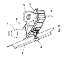
- FIG. 9 is an isometric view of the storage system as shown secured to a side rail of a bed and holding typical items as in FIG. 7 , here the bed shown in an inclined position.
- FIG. 10 is an isometric detail view of the storage system of FIG. 9 shown along line 10 - 10 .
- the storage system 10 may include a storage tray 12 , which may include a support surface 14 and one or more side walls 16 .
- a storage tray 12 which may include a support surface 14 and one or more side walls 16 .
- This configuration is not considered critical to the novelty of the invention, and therefore may be altered according to design needs.
- One large cavity with a single support surface 14 may be used.
- the side walls 16 in this form of the invention are shown to be in a substantially square orientation with a slightly smaller dimension at the support surface 14 end (bottom) relative to the open end at the top.
- This draft angle is provided in that the storage tray 12 may be produced from a plastic or other molded material, and the draft angle facilitates the removal of the part from the mold. In addition, this angle enables multiple storage trays 12 to be nested together when stacked for storage, thereby reducing storage and shipping costs. Though this form of the storage tray 12 of the invention may be preferable in many situations, a single cavity with the side wall 16 provided in an arced or oval shape may also be provided, thereby creating a single continuous side wall 16 though still encompassing the peripheral edge of the storage tray 12 . These are all design considerations considered to be included in the scope of the present invention.
- the support surface 14 of the storage tray 12 is provided as a structural element to support items placed on the support surface 14 , similar to the surface of a table or desk.
- a support surface 14 may also be provided in the second cavity 20 and the third cavity 22 of the storage tray 12 in addition to the first cavity 18 .
- each cavity may include a support surface 14 as shown.
- the support surface 14 of each cavity may be coplanar but, as shown here, it is not necessary.
- a slot 24 may be provided in one or more side walls 16 and may be continuous with an access hole 26 in one or more support surface 14 .
- the slot 24 may be in any or all of the side walls 16 of the storage tray 12 .
- the slot 24 and the access hole 26 may be used alone or in combination to provide access to electrical cords, tubes or any other tethering device, such as a call button, attached to an item to be placed in the storage tray 12 . Details to the function of the slot 24 and the access hole 26 will be presented in more detail further in this disclosure.
- a clamp 28 is provided and coupled to a clamp mount 30 , which may be mounted to a side wall 16 of the storage tray 12 .
- the clamp 28 may be received by the clamp mount 30 , which may include a clamp axis 31 about which the clamp 28 may rotate.
- the clamp 28 may be coupled to the clamp mount 30 in a manner such that the rotation of the clamp 28 with respect to the clamp mount 30 is restricted due to friction between contact surfaces of the clamp 28 and the clamp mount 30 .
- the frictional force may be adjusted by the tension in a clamp screw 33 , which may be used to secure the clamp 28 to the clamp mount 30 about the clamp axis 31 .
- the friction between the parts may be due to the normal force between the clamp 28 and the clamp mount 30 .
- bushing 35 may include a flange to provide a bearing surface with which to provide the frictional forces.
- structural material of the clamp 28 and clamp mount 30 may also be used as a bearing surface one to the other.
- the clamp 28 may include a first clamp half 32 spaced apart from a second clamp half 34 and a knob 36 with a threaded shaft 38 connecting the first clamp half 32 to the second clamp half 34 .
- the knob 36 may be coupled to the threaded shaft 38 so that rotation of the knob 36 , relative to the first clamp half 32 or the second clamp half 34 , enables the distance between the first clamp half 32 and the second clamp half 34 to be modified. By doing so, a rail or other structural element may be releasably clamped by “pinching” it between the first clamp half 32 and second clamp half 34 by rotation of the knob 36 .
- the knob 36 may otherwise include a female threaded portion connecting the knob 36 to the second clamp half 34 with the first clamp half 32 captured there between.
- the knob 36 may include a female threaded portion and the threaded shaft 38 may be fixed to the second clamp half 34 . Therefore the knob 36 may include a threaded portion that is female and receives a mating thread of the threaded shaft 38 associated with the second clamp half 34 or as previously stated, the threaded shaft 38 may be associated with the knob 36 and a female threaded portion may be included with the second clamp half 34 . In both conditions, the first clamp half 32 may be captured between the knob 36 and the second clamp half 34 .
- the first clamp half 32 may be desired to remain coplanar with the second clamp half 34 . If the only common support element coupling the first clamp half 32 with the second clamp half 34 is the threaded shaft 36 , the first clamp half 32 may be able to rotate about the threaded shaft 36 relative to the second clamp half 34 . In that it may be desired to prevent this rotation, a guide rod 40 may be provided that is fixed to either the first clamp half 32 or the second clamp half 34 , but not both. If the guide rod 40 is fixed to the second clamp half 34 , the guide rod 40 would be free to move relative to and guided by the first clamp half 32 . This combination may provide a guide to allow the space between the first clamp half 32 and the second clamp half 34 to be varied by movement of the knob 36 , but yet provide the first clamp half 32 and the second clamp half 34 to move in a common plane.
- the clamp 28 is shown as it may be rotatably mounted to the clamp mount 30 , enabling the clamp 28 to be rotated with respect to the storage tray 12 . Movement of the clamp 28 in this manner enables the storage system to maintain a specified orientation regardless of the support structure.
- FIGS. 7-10 An example of the use of the storage system 10 is shown in FIGS. 7-10 .
- a hospital bed 42 with a side rail 44 on each side of the bed 42 is shown in a flat position.
- the storage system 10 may be mounted onto the side rail 44 in a manner shown, with some objects supported by the storage system 10 .
- a more detailed view of the storage system 10 is shown in FIG. 8 .
- the clamp 28 may be secured to the side rail 44 , and the storage tray 12 may be positioned substantially parallel to the side rail 44 . Items commonly needed such as a bottle 46 and a call button 48 are shown as examples of items that may be stored in the storage tray 12 .
- the slot 24 allows access for the cord 50 of the call button 48 , so that the call button 48 can be positioned upright with the cord 50 extending out the bottom of the storage tray 12 . Without the slot 24 and hole 26 (not shown in this view) the cord 50 would have to be doubled back on itself and stuffed into the storage tray 12 , making it unstable and therefore more likely to fall out. If the call button 48 fell, it may make the call button 48 difficult or impossible to reach in the case of an emergency where the patient is unable to get out of bed to retrieve the call button 48 .
- the use of the slot 24 and hole 26 enable a secure and stable support for the call button by gently “capturing” the body of the call button 48 in the storage tray 12 and the cord 50 through the slot 24 and into the hole 26 .
- the patient may still be able to grasp and move the call button 48 while it is in the storage tray 12 , but it is less likely to be accidently dropped by a patient with limited cognizant faculties as the cord 50 acts as a tether to help support the call button 48 in the storage tray 12 .
- the bed 42 has been raised to a sitting position. This may be common with a patient that desires to converse with visitors, read or watch television.
- the side rails 44 are also inclined with respect to the horizontal.
- a typical tray that would attach directly to the side rail 44 would incline with the bed 42 and may spill the contents of the tray when in an elevated position.
- the storage system 10 as disclosed enables the clamp 28 to be rotated with respect to the storage tray 12 so that it can remain in a substantially horizontal position, if desired, or any other position. This enables the contents of the storage tray 12 to not spill, or at least to reduce the likelihood of the contents spilling out regardless of the angle of the bed 42 and with it the angle of the side rail 44 .
- the friction contact between the clamp 28 and the clamp support 30 enable the storage tray 12 to be rotated into any position and maintained in that position even if this angle is not perfectly parallel to the horizontal. Also, if the storage tray 12 is loaded with a heavier item on one side relative to the other side, the storage tray 12 may tip without the desire of the user in the absence of any friction or other locking system.
Abstract
An adjustable storage system may include a storage tray with a support surface and a clamp mount including a clamp axis. The clamp mount may be coupled to the storage tray with the clamp axis positioned substantially parallel to the support surface. The storage system may also include a clamp, rotatably coupled to the clamp mount about the clamp axis, whereby the tray may be adjustably positioned relative to the clamp about the clamp axis. When the storage system is secured to a frame, such as a bed rail, by use of the clamp, the support surface of the tray may be positioned substantially parallel to a reference plane, such as the floor, regardless of the angle of inclination of a frame relative to the reference plane. This enables stable support of objects supported by the tray when the bed is inclined or flat.
Description
- Priority is claimed under 35 U.S.C. §119(e) to U.S. Provisional Application No. 61/271,642, filed on Jul. 24, 2009, which is incorporated by reference herein.
- The present invention generally relates to storage service devices and, more particularly, to patient care accessories associated with a hospital bed or other support structure.
- Storage devices are useful in many applications. Any number of situations where someone may be located in a seat, chair or bed for a prolonged period, a storage system may be desired. From a cup holder while driving to a nightstand near the bed, devices to support personal items are desirable in many forms.
- One of the most useful applications for a storage device would be for a patient in a hospital bed. In this situation the user may spend long hours, awake and in need of service items such as a call button, water glass, television remote, and so on. Traditional night stands may be inadequate in that the patient's dexterity may be compromised due to the medical procedures or recovery from some other trauma, thus placing the patient in the hospital or rehabilitation setting. For example a person recovering from shoulder surgery may not be able to lean over to reach a bottle of water. In this case, bringing the bottle to the patient is important.
- With any storage system stability is important. An unstable surface may not be suited for supporting an object. That said, many beds, chairs and especially hospital beds are adjustable, and therefore change height or angle to more comfortable accommodate the needs of the patient. If a storage device is attached to the frame or rail of the bed, and the bed changes angle (inclines or declines) the storage system may move with it. Current storage systems fail to account for this change and must be removed, replaced and repositioned each time the bed is altered. If not, the contents of the storage system may end up on the floor or in the bed. A call button that cannot be reached by the patient because it is on the floor may be just as dangerous as a bottle of water spilled on the slick hard floor of a hospital room. Each of these is not desirable and potentially dangerous to the patient as well as visitors and hospital personnel.
- It should, therefore, be appreciated that there is a need for a storage system that may be mounted onto a hospital bed and easily adjusted to accommodate the angle of the bed. The present invention fulfills this need and others.
- The present invention provides an adjustable storage system which may include a storage tray with a support surface and a clamp mount including a clamp axis. The clamp mount may be coupled to the storage tray with the clamp axis positioned substantially parallel to the support surface. The storage system may also include a clamp, rotatably coupled to the clamp mount about the clamp axis, whereby the tray may be adjustably positioned relative to the clamp about the clamp axis.
- The storage tray may also include one or more side walls, positioned substantially orthogonal to the support surface. The clamp mount may be coupled to the side wall of the storage tray, wherein the side wall may include a slot. The support surface may include an access hole adapted to receive a cord, tube or other tethering device. The storage tray may also include a side wall positioned substantially orthogonal to the support surface. The side wall may include a slot that is continuous with the access hole in the support surface.
- The clamp may be comprised of a first clamp half spaced apart from a second clamp half and a knob with a threaded shaft connecting the first clamp half to the second clamp half, whereby rotation of the knob alters the space between the first clamp half and the second clamp half. The clamp assembly may also include a guide rod coupled to the first clamp half and received by the second clamp half, thereby restricting the movement of the first clamp half relative to the second clamp half to a common plane of movement.
- The storage tray may include more than one cavity, each cavity providing a support surface and at least one side wall. The storage tray may include two cavities, each with a side wall and each with a slot.
- An exemplary method for enabling storing of items for use with a hospital bed or other supporting device including a side rail, the method including a tray with the elements as described, including a clamp mount may be coupled to the storage tray with the clamp axis positioned substantially parallel to the support surface. The method may include the steps of: securing the clamp to the side rail of the bed; rotating the tray such that the support surface is at an angle relative to a reference plane; altering the angle of the side rail of the bed relative to the reference plane; and rotating the tray relative to the side rail to realign with the angle relative to the reference plane.
- For purposes of summarizing the invention and the advantages achieved over the prior art, certain advantages of the invention have been described herein above. Of course, it is to be understood that not necessarily all such advantages can be achieved in accordance with any particular embodiment of the invention. Thus, for example, those skilled in the art will recognize that the invention can be embodied or carried out in a manner that achieves or optimizes one advantage or group of advantages as taught herein without necessarily achieving other advantages as may be taught or suggested herein.
- All of these embodiments are intended to be within the scope of the invention herein disclosed. These and other embodiments of the present invention will become readily apparent to those skilled in the art from the following description of the preferred embodiments and drawings, the invention not being limited to any particular preferred embodiment(s) disclosed.
- Embodiments of the present invention will now be described, by way of example only, with reference to the following drawings, in which:
-
FIG. 1 is an isometric view of a storage system with a storage tray and a clamp movably mounted to the clamp tray and produced in accordance with the present invention. -
FIG. 2 is an isometric detail view shown along line 2-2 of the clamp of the storage system ofFIG. 1 . -
FIG. 3 is a top view of the storage device ofFIG. 1 -
FIG. 4 is a section view of the storage tray ofFIG. 3 cut along line 4-4. -
FIG. 5 is a side view of the storage system ofFIG. 1 . -
FIG. 6 is an isometric view of the storage system ofFIG. 1 with the clamp in a rotated position. -
FIG. 7 is an isometric view of the storage system ofFIG. 1 , shown secured to a side rail of a bed and holding typical items, the bed shown in a flat position. -
FIG. 8 is an isometric detail view of the storage system ofFIG. 7 shown along line 8-8. -
FIG. 9 is an isometric view of the storage system as shown secured to a side rail of a bed and holding typical items as inFIG. 7 , here the bed shown in an inclined position. -
FIG. 10 is an isometric detail view of the storage system ofFIG. 9 shown along line 10-10. - With reference to the illustrative drawings, and particularly to
FIGS. 1-5 , there is shown anadjustable storage system 10. Thestorage system 10 may include astorage tray 12, which may include asupport surface 14 and one ormore side walls 16. In this embodiment of the invention, there are three distinct cavities, thefirst cavity 18 and thesecond cavity 20 being smaller and distally positioned relative to a larger, and more centrally positioned,third cavity 22. This configuration is not considered critical to the novelty of the invention, and therefore may be altered according to design needs. One large cavity with asingle support surface 14 may be used. Theside walls 16 in this form of the invention are shown to be in a substantially square orientation with a slightly smaller dimension at thesupport surface 14 end (bottom) relative to the open end at the top. This draft angle is provided in that thestorage tray 12 may be produced from a plastic or other molded material, and the draft angle facilitates the removal of the part from the mold. In addition, this angle enablesmultiple storage trays 12 to be nested together when stacked for storage, thereby reducing storage and shipping costs. Though this form of the storage tray 12 of the invention may be preferable in many situations, a single cavity with theside wall 16 provided in an arced or oval shape may also be provided, thereby creating a singlecontinuous side wall 16 though still encompassing the peripheral edge of thestorage tray 12. These are all design considerations considered to be included in the scope of the present invention. - The
support surface 14 of thestorage tray 12 is provided as a structural element to support items placed on thesupport surface 14, similar to the surface of a table or desk. Asupport surface 14 may also be provided in thesecond cavity 20 and thethird cavity 22 of thestorage tray 12 in addition to thefirst cavity 18. Where more than one cavity is provided, each cavity may include asupport surface 14 as shown. Thesupport surface 14 of each cavity may be coplanar but, as shown here, it is not necessary. - A
slot 24 may be provided in one ormore side walls 16 and may be continuous with anaccess hole 26 in one ormore support surface 14. Theslot 24 may be in any or all of theside walls 16 of thestorage tray 12. Theslot 24 and theaccess hole 26 may be used alone or in combination to provide access to electrical cords, tubes or any other tethering device, such as a call button, attached to an item to be placed in thestorage tray 12. Details to the function of theslot 24 and theaccess hole 26 will be presented in more detail further in this disclosure. - A
clamp 28 is provided and coupled to aclamp mount 30, which may be mounted to aside wall 16 of thestorage tray 12. Theclamp 28 may be received by theclamp mount 30, which may include aclamp axis 31 about which theclamp 28 may rotate. Theclamp 28 may be coupled to theclamp mount 30 in a manner such that the rotation of theclamp 28 with respect to theclamp mount 30 is restricted due to friction between contact surfaces of theclamp 28 and theclamp mount 30. The frictional force may be adjusted by the tension in aclamp screw 33, which may be used to secure theclamp 28 to theclamp mount 30 about theclamp axis 31. The friction between the parts may be due to the normal force between theclamp 28 and theclamp mount 30. It may be desired to use abushing 35 or a pair ofbushings 35, one associated with theclamp 28 and theother bushing 35 with theclamp mount 30. Thebushings 35 may include a flange to provide a bearing surface with which to provide the frictional forces. In a similar manner the structural material of theclamp 28 and clamp mount 30 may also be used as a bearing surface one to the other. Each has advantages. The primary advantage to the use ofbushings 35 is this may be a replaceable part that as it wears, it may be replaced without damaging the structure of theclamp 28 or clampmount 30. - The
clamp 28 may include afirst clamp half 32 spaced apart from asecond clamp half 34 and aknob 36 with a threadedshaft 38 connecting thefirst clamp half 32 to thesecond clamp half 34. Theknob 36 may be coupled to the threadedshaft 38 so that rotation of theknob 36, relative to thefirst clamp half 32 or thesecond clamp half 34, enables the distance between thefirst clamp half 32 and thesecond clamp half 34 to be modified. By doing so, a rail or other structural element may be releasably clamped by “pinching” it between thefirst clamp half 32 andsecond clamp half 34 by rotation of theknob 36. Theknob 36 may otherwise include a female threaded portion connecting theknob 36 to thesecond clamp half 34 with thefirst clamp half 32 captured there between. Theknob 36 may include a female threaded portion and the threadedshaft 38 may be fixed to thesecond clamp half 34. Therefore theknob 36 may include a threaded portion that is female and receives a mating thread of the threadedshaft 38 associated with thesecond clamp half 34 or as previously stated, the threadedshaft 38 may be associated with theknob 36 and a female threaded portion may be included with thesecond clamp half 34. In both conditions, thefirst clamp half 32 may be captured between theknob 36 and thesecond clamp half 34. - The
first clamp half 32 may be desired to remain coplanar with thesecond clamp half 34. If the only common support element coupling thefirst clamp half 32 with thesecond clamp half 34 is the threadedshaft 36, thefirst clamp half 32 may be able to rotate about the threadedshaft 36 relative to thesecond clamp half 34. In that it may be desired to prevent this rotation, aguide rod 40 may be provided that is fixed to either thefirst clamp half 32 or thesecond clamp half 34, but not both. If theguide rod 40 is fixed to thesecond clamp half 34, theguide rod 40 would be free to move relative to and guided by thefirst clamp half 32. This combination may provide a guide to allow the space between thefirst clamp half 32 and thesecond clamp half 34 to be varied by movement of theknob 36, but yet provide thefirst clamp half 32 and thesecond clamp half 34 to move in a common plane. - With reference to
FIG. 6 , theclamp 28 is shown as it may be rotatably mounted to theclamp mount 30, enabling theclamp 28 to be rotated with respect to thestorage tray 12. Movement of theclamp 28 in this manner enables the storage system to maintain a specified orientation regardless of the support structure. - An example of the use of the
storage system 10 is shown inFIGS. 7-10 . InFIG. 7 ahospital bed 42 with aside rail 44 on each side of thebed 42 is shown in a flat position. Thestorage system 10 may be mounted onto theside rail 44 in a manner shown, with some objects supported by thestorage system 10. A more detailed view of thestorage system 10 is shown inFIG. 8 . Theclamp 28 may be secured to theside rail 44, and thestorage tray 12 may be positioned substantially parallel to theside rail 44. Items commonly needed such as abottle 46 and acall button 48 are shown as examples of items that may be stored in thestorage tray 12. Theslot 24 allows access for thecord 50 of thecall button 48, so that thecall button 48 can be positioned upright with thecord 50 extending out the bottom of thestorage tray 12. Without theslot 24 and hole 26 (not shown in this view) thecord 50 would have to be doubled back on itself and stuffed into thestorage tray 12, making it unstable and therefore more likely to fall out. If thecall button 48 fell, it may make thecall button 48 difficult or impossible to reach in the case of an emergency where the patient is unable to get out of bed to retrieve thecall button 48. The use of theslot 24 andhole 26 enable a secure and stable support for the call button by gently “capturing” the body of thecall button 48 in thestorage tray 12 and thecord 50 through theslot 24 and into thehole 26. The patient may still be able to grasp and move thecall button 48 while it is in thestorage tray 12, but it is less likely to be accidently dropped by a patient with limited cognizant faculties as thecord 50 acts as a tether to help support thecall button 48 in thestorage tray 12. - With reference to
FIGS. 9 and 10 , thebed 42 has been raised to a sitting position. This may be common with a patient that desires to converse with visitors, read or watch television. In this position of thebed 42, the side rails 44 are also inclined with respect to the horizontal. A typical tray that would attach directly to theside rail 44 would incline with thebed 42 and may spill the contents of the tray when in an elevated position. Thestorage system 10 as disclosed enables theclamp 28 to be rotated with respect to thestorage tray 12 so that it can remain in a substantially horizontal position, if desired, or any other position. This enables the contents of thestorage tray 12 to not spill, or at least to reduce the likelihood of the contents spilling out regardless of the angle of thebed 42 and with it the angle of theside rail 44. The friction contact between theclamp 28 and theclamp support 30 enable thestorage tray 12 to be rotated into any position and maintained in that position even if this angle is not perfectly parallel to the horizontal. Also, if thestorage tray 12 is loaded with a heavier item on one side relative to the other side, thestorage tray 12 may tip without the desire of the user in the absence of any friction or other locking system. - The foregoing detailed description of the present invention is provided for purposes of illustration, and it is not intended to be exhaustive or to limit the invention to the particular embodiment shown. The embodiments may provide different capabilities and benefits, depending on the configuration used to implement key features of the invention.
Claims (23)
1. An adjustable storage system, comprising:
a storage tray including a support surface;
a clamp mount including a clamp axis, the clamp mount coupled to the storage tray with the clamp axis substantially parallel to the support surface; and
a clamp, rotatably coupled to the clamp mount about the clamp axis, whereby the tray may be adjustably positioned relative to the clamp about the clamp axis.
2. The storage system according to claim 1 , wherein the storage tray includes a side wall, substantially orthogonal to the support surface.
3. The storage system of claim 2 , wherein the clamp mount is coupled to the side wall of the storage tray.
4. The storage system of claim 2 , wherein the side wall includes a slot.
5. The storage system of claim 1 , wherein the support surface includes an access hole.
6. The storage system of claim 5 , further comprising a side wall orthogonal to the support surface, the side wall including a slot that is continuous with the access hole.
7. The storage system of claim 1 , wherein the clamp is comprised of a first clamp half spaced apart from a second clamp half and a knob with a threaded portion connecting the first clamp half to the second clamp half, whereby rotation of the knob alters the space between the first clamp half and the second clamp half.
8. The storage system of claim 7 , further comprising a guide rod coupled to the first clamp half and received by the second clamp half, thereby restricting the movement of the first clamp half relative to the second clamp half to a common plane.
9. The storage system of claim 1 , wherein the storage tray includes more than one cavity, each cavity providing a support surface and at least one side wall.
10. The storage system of claim 9 , wherein the storage tray includes two cavities each with a side wall including a slot.
11. The storage system of claim 1 , further comprising a clamp screw to secure the clamp to the clamp mount, thereby providing a frictional coupling of the clamp mount to the clamp.
12. An adjustable storage system, comprising:
a storage tray including a support surface; and
a clamp means, including a clamp axis substantially parallel to the support surface of the storage tray, the clamp means coupled to the storage tray and adapted for rotational articulation with the storage tray about the clamp axis.
13. The storage system according to claim 12 , wherein the storage tray includes a side wall, substantially orthogonal to the support surface.
14. The storage system of claim 13 , wherein the clamp means is coupled to the side wall of the storage tray.
15. The storage system of claim 13 , wherein the side wall includes a slot.
16. The storage system of claim 12 , wherein the support surface includes an access hole.
17. The storage system of claim 16 , further comprising a side wall orthogonal to the support surface, the side wall including a slot that is continuous with the access hole.
18. The storage system of claim 12 , wherein the clamp means is comprised of a first clamp half spaced apart from a second clamp half and a knob with a threaded portion connecting the first clamp half to the second clamp half, whereby rotation of the knob alters the space between the first clamp half and the second clamp half.
19. The storage system of claim 18 , further comprising a guide rod coupled to the first clamp half and received by the second clamp half, thereby restricting the movement of the first clamp half relative to the second clamp half to a common plane.
20. The storage system of claim 12 , wherein the storage tray includes more than one cavity, each cavity providing a support surface and at least one side wall.
21. The storage system of claim 20 , wherein the storage tray includes two cavities each with a side wall including a slot.
22. A storage system including a tray with a support surface, the system adapted for use with a hospital bed, the improvement including:
a clamp means coupled to the storage tray, whereby movement of the storage tray relative to the clamp means is restricted to movement in a plane substantially perpendicular to the support surface of the storage tray.
23. A method of storing items for use with a hospital bed including a side rail, the method including a tray with a support surface and a clamp including a clamp axis substantially parallel to the support surface of the storage tray, the clamp coupled to the storage tray and adapted for rotational articulation with the storage tray about the clamp axis, the method of storing including the steps of:
securing the clamp to the side rail of the bed;
rotating the tray such that the support surface is at an angle relative to a reference plane;
altering the angle of the side rail of the bed relative to the reference plane; and
rotating the tray relative to the side rail to realign with the angle relative to the reference plane.
Priority Applications (1)
| Application Number | Priority Date | Filing Date | Title |
|---|---|---|---|
| US12/800,544 US20110016632A1 (en) | 2009-07-24 | 2010-05-18 | Adjustable storage system |
Applications Claiming Priority (2)
| Application Number | Priority Date | Filing Date | Title |
|---|---|---|---|
| US27164209P | 2009-07-24 | 2009-07-24 | |
| US12/800,544 US20110016632A1 (en) | 2009-07-24 | 2010-05-18 | Adjustable storage system |
Publications (1)
| Publication Number | Publication Date |
|---|---|
| US20110016632A1 true US20110016632A1 (en) | 2011-01-27 |
Family
ID=43495998
Family Applications (1)
| Application Number | Title | Priority Date | Filing Date |
|---|---|---|---|
| US12/800,544 Abandoned US20110016632A1 (en) | 2009-07-24 | 2010-05-18 | Adjustable storage system |
Country Status (1)
| Country | Link |
|---|---|
| US (1) | US20110016632A1 (en) |
Cited By (9)
| Publication number | Priority date | Publication date | Assignee | Title |
|---|---|---|---|---|
| US20130112636A1 (en) * | 2011-09-19 | 2013-05-09 | Stephanie Williams-Shelton | Attachable Drawing Rack |
| US9072637B1 (en) * | 2012-07-13 | 2015-07-07 | Kathleen F. Puri | Self leveling cradle and removable container |
| USD804846S1 (en) * | 2016-12-01 | 2017-12-12 | Paris Presents Incorporated | Cosmetics caddy |
| USD808188S1 (en) * | 2016-12-01 | 2018-01-23 | Paris Presents Incorporated | Cosmetics caddy |
| US20180110662A1 (en) * | 2016-10-20 | 2018-04-26 | Morzine Medical Llc | Multi-Purpose Litter Clamp and Attachments |
| USD825967S1 (en) * | 2017-03-09 | 2018-08-21 | T.H.Y. Designs, L.L.C. | Pocket holder for a music stand |
| USD845027S1 (en) | 2018-02-08 | 2019-04-09 | Paris Presents Incorporated | Storage device |
| USD845028S1 (en) | 2018-02-08 | 2019-04-09 | Paris Presents Incorporated | Storage device |
| US20200206051A1 (en) * | 2018-12-31 | 2020-07-02 | Eminent Medical Supplies LLC | Hospital Bed Equipment Holder |
Citations (58)
| Publication number | Priority date | Publication date | Assignee | Title |
|---|---|---|---|---|
| US932236A (en) * | 1909-04-13 | 1909-08-24 | Hugh L Appleton | Bed attachment. |
| US979070A (en) * | 1910-09-01 | 1910-12-20 | Adolph Hoffman | Adjustable support for drawing-boards. |
| US1199553A (en) * | 1915-06-03 | 1916-09-26 | Meinecke & Company | Surgical-accessory-supporting appliance. |
| US1866258A (en) * | 1929-07-08 | 1932-07-05 | Eva W Jimmerson | Attachment for hospital beds |
| US2193647A (en) * | 1937-04-05 | 1940-03-12 | Rush | Bed tray |
| US2376507A (en) * | 1942-12-02 | 1945-05-22 | Frank R Ruther | Splint support |
| US2558366A (en) * | 1949-07-12 | 1951-06-26 | Madlena John | Bedrail-supported tray |
| US2893675A (en) * | 1956-08-27 | 1959-07-07 | Aladdin Mfg Company | Beverage holder |
| US2912205A (en) * | 1957-08-23 | 1959-11-10 | Edward P Toune | Paint bucket holder |
| US3054122A (en) * | 1960-01-26 | 1962-09-18 | Noreen T Sarkus | Combined bed tray and night stand |
| US3131900A (en) * | 1962-05-15 | 1964-05-05 | Robert J Anderson | Self leveling paint can holder attachment for ladders |
| US3233940A (en) * | 1964-05-21 | 1966-02-08 | Jr John F Tooley | Lawn furniture multipurpose arm |
| US3269683A (en) * | 1965-05-21 | 1966-08-30 | Lawrence P Shinaver | Carrier attachment for open-top containers |
| US3276045A (en) * | 1964-08-21 | 1966-10-04 | George P Bement | Bed tray and bed in combination therewith |
| US3400829A (en) * | 1966-09-12 | 1968-09-10 | Sydney M. Youngson | Baby crib tray |
| US3734439A (en) * | 1971-10-22 | 1973-05-22 | Aladdin Manuf Co | Beverage container receptacle and clamp |
| US3987993A (en) * | 1975-12-22 | 1976-10-26 | Hopkins Jeffrey E | Paint can support and brush receptacle |
| US4357881A (en) * | 1980-11-03 | 1982-11-09 | Long Harold D De | Hospital bed tray |
| US4431154A (en) * | 1982-05-10 | 1984-02-14 | Hamm H Keith | Holder for mounting on a rail and the like |
| US4504992A (en) * | 1982-12-06 | 1985-03-19 | Herron Robert G | Hospital bed telephone holder |
| US4535923A (en) * | 1983-03-25 | 1985-08-20 | Manke James E | Automobile beverage holding device |
| US4547092A (en) * | 1984-02-21 | 1985-10-15 | Hamilton Industries | Accessory clamp for medical table |
| US4560128A (en) * | 1984-08-03 | 1985-12-24 | Willeby Randy C | Drink holder |
| US4728147A (en) * | 1986-07-31 | 1988-03-01 | Dutton Ronald W | Lawn chair accessory |
| US4754902A (en) * | 1986-09-18 | 1988-07-05 | Opfergelt Robert F | Beverage caddy for bicycles |
| US4836403A (en) * | 1987-12-03 | 1989-06-06 | Blackmon Laura M | Multi-use tray with accessories |
| US4844399A (en) * | 1988-08-15 | 1989-07-04 | Harm John E | Golf bag cart beverage holder |
| US4848622A (en) * | 1988-12-06 | 1989-07-18 | James Kroetsch | Drinking device for the disabled |
| US4850282A (en) * | 1988-07-18 | 1989-07-25 | Stephen Postic | Portable food tray |
| US4948197A (en) * | 1989-03-27 | 1990-08-14 | Sansing Dayna L | Child shampooing chair |
| US4949924A (en) * | 1987-06-08 | 1990-08-21 | Carmody Burr T | Support fixture for mounting on railings and the like |
| US5127188A (en) * | 1990-07-18 | 1992-07-07 | Integrated Plastics Limited | Planter box bracket |
| US5287575A (en) * | 1992-11-09 | 1994-02-22 | Allen Medical Systems | Hand table |
| US5320263A (en) * | 1993-04-12 | 1994-06-14 | Kobylack Richard L | Golf cart beverage support |
| US5359741A (en) * | 1993-04-21 | 1994-11-01 | Brian Lang | Rotatable and removable bed tray |
| US5362021A (en) * | 1992-05-11 | 1994-11-08 | Phillips Medical Group, Inc. | Multi-adjustable surgical tray apparatus |
| US5370246A (en) * | 1992-08-05 | 1994-12-06 | Traynor; Joan G. | Article storage caddy |
| US5472164A (en) * | 1993-12-09 | 1995-12-05 | Howard S. Contee, Jr. | Multi purpose grill hanger bracket |
| US5478041A (en) * | 1992-08-14 | 1995-12-26 | Manova Products Inc. | Clamping and holding device |
| US5484129A (en) * | 1994-12-20 | 1996-01-16 | Megal; Michael D. | Beverage holder arrangement for a golf cart |
| US5758374A (en) * | 1996-05-20 | 1998-06-02 | Ronci; Samuel | Portable table assembly |
| US5836026A (en) * | 1997-05-22 | 1998-11-17 | Reed; Michael C. | Orthopedic trapeze with self-locking rotatable mechanism |
| US5865412A (en) * | 1997-03-26 | 1999-02-02 | Post Primitive Technology, Inc. | Beverage container holder |
| US6023800A (en) * | 1997-05-09 | 2000-02-15 | Midmark Corporation | Removable accessory for a surgical table |
| US6195820B1 (en) * | 1999-05-27 | 2001-03-06 | Hill-Rom, Inc. | Pivoting hand table |
| US6253399B1 (en) * | 1997-05-02 | 2001-07-03 | William J. Wagner | Tray caddy |
| US6322028B1 (en) * | 2000-05-10 | 2001-11-27 | Mark A. Fleckenstein | Container supporting device |
| US6325350B1 (en) * | 1999-09-17 | 2001-12-04 | Salvatore Mancuso | Pendulous pivotable cup holder |
| US6601813B1 (en) * | 1999-03-25 | 2003-08-05 | Kevin F. Kager | Hair styling accessory holder |
| US6671904B2 (en) * | 2000-10-30 | 2004-01-06 | Steris, Inc. | Surgical table top and accessory clamp used thereon |
| US6766912B1 (en) * | 1996-11-08 | 2004-07-27 | Dorian Gibbs | Secured receptacle holder |
| US6912959B2 (en) * | 2001-03-12 | 2005-07-05 | Steris Inc. | Surgical table and clamp system |
| US7043778B1 (en) * | 2005-06-09 | 2006-05-16 | Barbara Georgitsis | Apparatus for crib attachment |
| US7398951B1 (en) * | 2005-01-05 | 2008-07-15 | Vivian Sugalski | Urinal holder |
| US20080172791A1 (en) * | 2007-01-22 | 2008-07-24 | Walczyk Stephen L | Surgical support for patient limb |
| US7540243B2 (en) * | 2000-05-05 | 2009-06-02 | Hill-Rom Services, Inc. | Overbed table for use with patient support |
| US20110126353A1 (en) * | 2009-05-27 | 2011-06-02 | Bedside Butler Inc. | Bedside assistance apparatus |
| US8051515B1 (en) * | 2008-08-12 | 2011-11-08 | Bob Kring | Surgical bed clamp apparatus |
-
2010
- 2010-05-18 US US12/800,544 patent/US20110016632A1/en not_active Abandoned
Patent Citations (58)
| Publication number | Priority date | Publication date | Assignee | Title |
|---|---|---|---|---|
| US932236A (en) * | 1909-04-13 | 1909-08-24 | Hugh L Appleton | Bed attachment. |
| US979070A (en) * | 1910-09-01 | 1910-12-20 | Adolph Hoffman | Adjustable support for drawing-boards. |
| US1199553A (en) * | 1915-06-03 | 1916-09-26 | Meinecke & Company | Surgical-accessory-supporting appliance. |
| US1866258A (en) * | 1929-07-08 | 1932-07-05 | Eva W Jimmerson | Attachment for hospital beds |
| US2193647A (en) * | 1937-04-05 | 1940-03-12 | Rush | Bed tray |
| US2376507A (en) * | 1942-12-02 | 1945-05-22 | Frank R Ruther | Splint support |
| US2558366A (en) * | 1949-07-12 | 1951-06-26 | Madlena John | Bedrail-supported tray |
| US2893675A (en) * | 1956-08-27 | 1959-07-07 | Aladdin Mfg Company | Beverage holder |
| US2912205A (en) * | 1957-08-23 | 1959-11-10 | Edward P Toune | Paint bucket holder |
| US3054122A (en) * | 1960-01-26 | 1962-09-18 | Noreen T Sarkus | Combined bed tray and night stand |
| US3131900A (en) * | 1962-05-15 | 1964-05-05 | Robert J Anderson | Self leveling paint can holder attachment for ladders |
| US3233940A (en) * | 1964-05-21 | 1966-02-08 | Jr John F Tooley | Lawn furniture multipurpose arm |
| US3276045A (en) * | 1964-08-21 | 1966-10-04 | George P Bement | Bed tray and bed in combination therewith |
| US3269683A (en) * | 1965-05-21 | 1966-08-30 | Lawrence P Shinaver | Carrier attachment for open-top containers |
| US3400829A (en) * | 1966-09-12 | 1968-09-10 | Sydney M. Youngson | Baby crib tray |
| US3734439A (en) * | 1971-10-22 | 1973-05-22 | Aladdin Manuf Co | Beverage container receptacle and clamp |
| US3987993A (en) * | 1975-12-22 | 1976-10-26 | Hopkins Jeffrey E | Paint can support and brush receptacle |
| US4357881A (en) * | 1980-11-03 | 1982-11-09 | Long Harold D De | Hospital bed tray |
| US4431154A (en) * | 1982-05-10 | 1984-02-14 | Hamm H Keith | Holder for mounting on a rail and the like |
| US4504992A (en) * | 1982-12-06 | 1985-03-19 | Herron Robert G | Hospital bed telephone holder |
| US4535923A (en) * | 1983-03-25 | 1985-08-20 | Manke James E | Automobile beverage holding device |
| US4547092A (en) * | 1984-02-21 | 1985-10-15 | Hamilton Industries | Accessory clamp for medical table |
| US4560128A (en) * | 1984-08-03 | 1985-12-24 | Willeby Randy C | Drink holder |
| US4728147A (en) * | 1986-07-31 | 1988-03-01 | Dutton Ronald W | Lawn chair accessory |
| US4754902A (en) * | 1986-09-18 | 1988-07-05 | Opfergelt Robert F | Beverage caddy for bicycles |
| US4949924A (en) * | 1987-06-08 | 1990-08-21 | Carmody Burr T | Support fixture for mounting on railings and the like |
| US4836403A (en) * | 1987-12-03 | 1989-06-06 | Blackmon Laura M | Multi-use tray with accessories |
| US4850282A (en) * | 1988-07-18 | 1989-07-25 | Stephen Postic | Portable food tray |
| US4844399A (en) * | 1988-08-15 | 1989-07-04 | Harm John E | Golf bag cart beverage holder |
| US4848622A (en) * | 1988-12-06 | 1989-07-18 | James Kroetsch | Drinking device for the disabled |
| US4948197A (en) * | 1989-03-27 | 1990-08-14 | Sansing Dayna L | Child shampooing chair |
| US5127188A (en) * | 1990-07-18 | 1992-07-07 | Integrated Plastics Limited | Planter box bracket |
| US5362021A (en) * | 1992-05-11 | 1994-11-08 | Phillips Medical Group, Inc. | Multi-adjustable surgical tray apparatus |
| US5370246A (en) * | 1992-08-05 | 1994-12-06 | Traynor; Joan G. | Article storage caddy |
| US5478041A (en) * | 1992-08-14 | 1995-12-26 | Manova Products Inc. | Clamping and holding device |
| US5287575A (en) * | 1992-11-09 | 1994-02-22 | Allen Medical Systems | Hand table |
| US5320263A (en) * | 1993-04-12 | 1994-06-14 | Kobylack Richard L | Golf cart beverage support |
| US5359741A (en) * | 1993-04-21 | 1994-11-01 | Brian Lang | Rotatable and removable bed tray |
| US5472164A (en) * | 1993-12-09 | 1995-12-05 | Howard S. Contee, Jr. | Multi purpose grill hanger bracket |
| US5484129A (en) * | 1994-12-20 | 1996-01-16 | Megal; Michael D. | Beverage holder arrangement for a golf cart |
| US5758374A (en) * | 1996-05-20 | 1998-06-02 | Ronci; Samuel | Portable table assembly |
| US6766912B1 (en) * | 1996-11-08 | 2004-07-27 | Dorian Gibbs | Secured receptacle holder |
| US5865412A (en) * | 1997-03-26 | 1999-02-02 | Post Primitive Technology, Inc. | Beverage container holder |
| US6253399B1 (en) * | 1997-05-02 | 2001-07-03 | William J. Wagner | Tray caddy |
| US6023800A (en) * | 1997-05-09 | 2000-02-15 | Midmark Corporation | Removable accessory for a surgical table |
| US5836026A (en) * | 1997-05-22 | 1998-11-17 | Reed; Michael C. | Orthopedic trapeze with self-locking rotatable mechanism |
| US6601813B1 (en) * | 1999-03-25 | 2003-08-05 | Kevin F. Kager | Hair styling accessory holder |
| US6195820B1 (en) * | 1999-05-27 | 2001-03-06 | Hill-Rom, Inc. | Pivoting hand table |
| US6325350B1 (en) * | 1999-09-17 | 2001-12-04 | Salvatore Mancuso | Pendulous pivotable cup holder |
| US7540243B2 (en) * | 2000-05-05 | 2009-06-02 | Hill-Rom Services, Inc. | Overbed table for use with patient support |
| US6322028B1 (en) * | 2000-05-10 | 2001-11-27 | Mark A. Fleckenstein | Container supporting device |
| US6671904B2 (en) * | 2000-10-30 | 2004-01-06 | Steris, Inc. | Surgical table top and accessory clamp used thereon |
| US6912959B2 (en) * | 2001-03-12 | 2005-07-05 | Steris Inc. | Surgical table and clamp system |
| US7398951B1 (en) * | 2005-01-05 | 2008-07-15 | Vivian Sugalski | Urinal holder |
| US7043778B1 (en) * | 2005-06-09 | 2006-05-16 | Barbara Georgitsis | Apparatus for crib attachment |
| US20080172791A1 (en) * | 2007-01-22 | 2008-07-24 | Walczyk Stephen L | Surgical support for patient limb |
| US8051515B1 (en) * | 2008-08-12 | 2011-11-08 | Bob Kring | Surgical bed clamp apparatus |
| US20110126353A1 (en) * | 2009-05-27 | 2011-06-02 | Bedside Butler Inc. | Bedside assistance apparatus |
Cited By (12)
| Publication number | Priority date | Publication date | Assignee | Title |
|---|---|---|---|---|
| US20130112636A1 (en) * | 2011-09-19 | 2013-05-09 | Stephanie Williams-Shelton | Attachable Drawing Rack |
| US9538864B2 (en) * | 2011-09-19 | 2017-01-10 | Stephanie Williams | Phlebotomist's utility rack with attachment features |
| US9072637B1 (en) * | 2012-07-13 | 2015-07-07 | Kathleen F. Puri | Self leveling cradle and removable container |
| US20180110662A1 (en) * | 2016-10-20 | 2018-04-26 | Morzine Medical Llc | Multi-Purpose Litter Clamp and Attachments |
| US10561547B2 (en) * | 2016-10-20 | 2020-02-18 | Morzine Medical, LLC | Multi-purpose litter clamp and attachments |
| USD804846S1 (en) * | 2016-12-01 | 2017-12-12 | Paris Presents Incorporated | Cosmetics caddy |
| USD808188S1 (en) * | 2016-12-01 | 2018-01-23 | Paris Presents Incorporated | Cosmetics caddy |
| USD825967S1 (en) * | 2017-03-09 | 2018-08-21 | T.H.Y. Designs, L.L.C. | Pocket holder for a music stand |
| USD845027S1 (en) | 2018-02-08 | 2019-04-09 | Paris Presents Incorporated | Storage device |
| USD845028S1 (en) | 2018-02-08 | 2019-04-09 | Paris Presents Incorporated | Storage device |
| US20200206051A1 (en) * | 2018-12-31 | 2020-07-02 | Eminent Medical Supplies LLC | Hospital Bed Equipment Holder |
| US11504288B2 (en) * | 2018-12-31 | 2022-11-22 | Eminent Medical Supplies LLC | Hospital bed equipment holder |
Similar Documents
| Publication | Publication Date | Title |
|---|---|---|
| US20110016632A1 (en) | Adjustable storage system | |
| US20210253305A1 (en) | Container with one or more tray retention portions and support stand | |
| US7938372B2 (en) | Free standing or vehicle mounted 6-axis positionable tray, positionable shelf, cup-holder, stanchion apparatus and related systems | |
| US5630566A (en) | Portable ergonomic work station | |
| US6419312B1 (en) | Incrementally slidable high chair tray with quick release | |
| US8015929B2 (en) | Tray apparatus | |
| US5408713A (en) | Head-rest | |
| US8316777B1 (en) | Overbed table with arm supports | |
| US7398951B1 (en) | Urinal holder | |
| US20110017105A1 (en) | Recliner laptop desk | |
| US6748874B2 (en) | Shelf for removable attachment to support | |
| US20150265062A1 (en) | System for keeping a pillow in place | |
| US7537185B2 (en) | Swiveling beverage holder | |
| US20160263310A1 (en) | Mobile One-Handed Tube-Feeding Syringe Support | |
| US8347791B1 (en) | Computer keyboard and mouse tray assembly | |
| US6802265B1 (en) | Universal table comprising an organizer base with detachable pockets; connecting, supporting, and adjustment mechanisms; and a multi-positional table | |
| US5596780A (en) | Surgery patient headrest | |
| KR20080066399A (en) | A cushion for nursing | |
| US7100977B2 (en) | Detachable support arm | |
| KR100979301B1 (en) | A Reading desk for using in the lying state | |
| US11736864B2 (en) | Headphone stand | |
| US10548791B2 (en) | Arm support for supine patient | |
| US20110186241A1 (en) | Privacy Bed Shade | |
| US6516729B1 (en) | Freestanding companion system consisting of an organizer base, a table and the connecting, supporting, and adjustment mechanisms | |
| CN215020952U (en) | Simple sickbed dining table |
Legal Events
| Date | Code | Title | Description |
|---|---|---|---|
| STCB | Information on status: application discontinuation |
Free format text: ABANDONED -- FAILURE TO RESPOND TO AN OFFICE ACTION |