US20110054343A1 - Monitoring system - Google Patents
Monitoring system Download PDFInfo
- Publication number
- US20110054343A1 US20110054343A1 US11/993,219 US99321906A US2011054343A1 US 20110054343 A1 US20110054343 A1 US 20110054343A1 US 99321906 A US99321906 A US 99321906A US 2011054343 A1 US2011054343 A1 US 2011054343A1
- Authority
- US
- United States
- Prior art keywords
- processing system
- impedance
- subject
- determining
- method includes
- Prior art date
- Legal status (The legal status is an assumption and is not a legal conclusion. Google has not performed a legal analysis and makes no representation as to the accuracy of the status listed.)
- Abandoned
Links
Images


Classifications
-
- A—HUMAN NECESSITIES
- A61—MEDICAL OR VETERINARY SCIENCE; HYGIENE
- A61B—DIAGNOSIS; SURGERY; IDENTIFICATION
- A61B5/00—Measuring for diagnostic purposes; Identification of persons
- A61B5/05—Detecting, measuring or recording for diagnosis by means of electric currents or magnetic fields; Measuring using microwaves or radio waves
- A61B5/053—Measuring electrical impedance or conductance of a portion of the body
-
- A—HUMAN NECESSITIES
- A61—MEDICAL OR VETERINARY SCIENCE; HYGIENE
- A61B—DIAGNOSIS; SURGERY; IDENTIFICATION
- A61B5/00—Measuring for diagnostic purposes; Identification of persons
- A61B5/02—Detecting, measuring or recording pulse, heart rate, blood pressure or blood flow; Combined pulse/heart-rate/blood pressure determination; Evaluating a cardiovascular condition not otherwise provided for, e.g. using combinations of techniques provided for in this group with electrocardiography or electroauscultation; Heart catheters for measuring blood pressure
- A61B5/026—Measuring blood flow
- A61B5/029—Measuring or recording blood output from the heart, e.g. minute volume
-
- A—HUMAN NECESSITIES
- A61—MEDICAL OR VETERINARY SCIENCE; HYGIENE
- A61B—DIAGNOSIS; SURGERY; IDENTIFICATION
- A61B5/00—Measuring for diagnostic purposes; Identification of persons
- A61B5/05—Detecting, measuring or recording for diagnosis by means of electric currents or magnetic fields; Measuring using microwaves or radio waves
- A61B5/053—Measuring electrical impedance or conductance of a portion of the body
- A61B5/0537—Measuring body composition by impedance, e.g. tissue hydration or fat content
-
- A—HUMAN NECESSITIES
- A61—MEDICAL OR VETERINARY SCIENCE; HYGIENE
- A61B—DIAGNOSIS; SURGERY; IDENTIFICATION
- A61B5/00—Measuring for diagnostic purposes; Identification of persons
- A61B5/06—Devices, other than using radiation, for detecting or locating foreign bodies ; determining position of probes within or on the body of the patient
- A61B5/061—Determining position of a probe within the body employing means separate from the probe, e.g. sensing internal probe position employing impedance electrodes on the surface of the body
- A61B5/063—Determining position of a probe within the body employing means separate from the probe, e.g. sensing internal probe position employing impedance electrodes on the surface of the body using impedance measurements
-
- A—HUMAN NECESSITIES
- A61—MEDICAL OR VETERINARY SCIENCE; HYGIENE
- A61B—DIAGNOSIS; SURGERY; IDENTIFICATION
- A61B5/00—Measuring for diagnostic purposes; Identification of persons
- A61B5/48—Other medical applications
- A61B5/4842—Monitoring progression or stage of a disease
-
- A—HUMAN NECESSITIES
- A61—MEDICAL OR VETERINARY SCIENCE; HYGIENE
- A61B—DIAGNOSIS; SURGERY; IDENTIFICATION
- A61B5/00—Measuring for diagnostic purposes; Identification of persons
- A61B5/48—Other medical applications
- A61B5/4869—Determining body composition
- A61B5/4875—Hydration status, fluid retention of the body
- A61B5/4878—Evaluating oedema
-
- A—HUMAN NECESSITIES
- A61—MEDICAL OR VETERINARY SCIENCE; HYGIENE
- A61B—DIAGNOSIS; SURGERY; IDENTIFICATION
- A61B5/00—Measuring for diagnostic purposes; Identification of persons
- A61B5/72—Signal processing specially adapted for physiological signals or for diagnostic purposes
- A61B5/7271—Specific aspects of physiological measurement analysis
- A61B5/7278—Artificial waveform generation or derivation, e.g. synthesising signals from measured signals
-
- A—HUMAN NECESSITIES
- A61—MEDICAL OR VETERINARY SCIENCE; HYGIENE
- A61B—DIAGNOSIS; SURGERY; IDENTIFICATION
- A61B5/00—Measuring for diagnostic purposes; Identification of persons
- A61B5/74—Details of notification to user or communication with user or patient ; user input means
- A61B5/742—Details of notification to user or communication with user or patient ; user input means using visual displays
- A61B5/744—Displaying an avatar, e.g. an animated cartoon character
-
- A—HUMAN NECESSITIES
- A61—MEDICAL OR VETERINARY SCIENCE; HYGIENE
- A61B—DIAGNOSIS; SURGERY; IDENTIFICATION
- A61B2560/00—Constructional details of operational features of apparatus; Accessories for medical measuring apparatus
- A61B2560/02—Operational features
- A61B2560/0266—Operational features for monitoring or limiting apparatus function
- A61B2560/0271—Operational features for monitoring or limiting apparatus function using a remote monitoring unit
Definitions
- the present invention relates to a method and apparatus for monitoring biological parameters, and in particular to a method and apparatus for performing impedance measurements.
- One existing technique for determining biological parameters relating to a subject involves the use of bioelectrical impedance. This involves measuring the electrical impedance of a subject's body using a series of electrodes placed on the skin surface. Changes in electrical impedance at the body's surface are used to determine parameters, such as changes in fluid levels, associated with the cardiac cycle or oedema.
- Lymphoedema is a condition characterised by excess protein and oedema in the tissues as a result of reduced lymphatic transport capacity and/or reduced tissue proteolytic capacity in the presence of a normal lymphatic load. Acquired, or secondary lymphoedema, is caused by damaged or blocked lymphatic vessels. “The commonest inciting events are surgery and/or radiotherapy. However, onset of lymphoedema is unpredictable and may develop within days of its cause or at any time during a period of many years after that cause.
- WO00/79255 describes a method of detection of oedema by measuring bioelectrical impedance at two different anatomical regions in the same subject at a single low frequency alternating current. The two measurements are analysed to obtain an indication of the presence of tissue oedema by comparing with data obtained from a normal population.
- machines are only adapted to provide only one form of impedance analysis and as a result, provide a standard output that must then be interpreted by the operator.
- different operating modes it is necessary for the operator of the machine to be aware of any intricacies associated with the selected measurement mode, as well as being able to interpret the different outputs that may be available.
- the present invention provides a method of performing impedance measurements on a subject, the method including, in a processing system:
- the method includes, in the processing system:
- the representation includes, for each lead connection, a respective colour indication, the colour indication being indicative of a colour for a respective lead.
- the method includes, in the processing system:
- each measurement is performed for a corresponding body segment.
- the method includes:
- the method includes, in the processing system:
- the impedance measurement type is for determining at least one of:
- the method includes, in the processing system:
- the method includes, in the processing system:
- the representation is in the form of at least one of
- the method includes, in the processing system:
- the method includes, in the processing system:
- the method includes in the processing system:
- the subject parameter is at least one of
- the method includes, in the processing system, determining the at least one subject parameter from a remote database.
- the method includes, in the processing system:
- the processing system is coupled to a reader for sensing coded data from a surface, and wherein the method includes, in the processing system:
- the subject identification device is a bracelet having coded data disposed thereon.
- the method includes, in the processing system:
- the positioning of the electrodes is performed in accordance with the theory of equal potentials.
- the positioning of the electrodes includes:
- processing system is coupled to a monitoring unit, and wherein the method includes, in the processing system:
- the monitoring unit includes at least two channels, each channel being adapted to measure the impedance across a respective body segment, and wherein the method includes, in the processing system, causing at least one impedance measurement to be performed using each channel.
- the monitoring unit includes a processor, and wherein the processor is for:
- the method includes, causing the impedance measurement to be performed by:
- the present invention provides apparatus for performing impedance measurements on a subject, the apparatus including a processing system for:
- the present invention provides a method of performing impedance measurements on a subject, the method including, in a processing system:
- the method includes, in the processing system:
- the representation is in the form of at least one of
- the method includes, in the processing system:
- the method includes in the processing system:
- the subject parameter is at least one of:
- the method includes, in the processing system:
- the present invention provides apparatus for performing impedance measurements on a subject, the apparatus including a processing system for:
- the present invention provides a method of performing impedance measurements on a subject, the method including, in a processing system:
- processing system is coupled to a monitoring unit, and wherein the method includes, in the processing system:
- the method includes using a monitoring unit including a processor, and wherein the processor is for:
- the method includes, causing the impedance measurement to be performed by:
- the method includes using a monitoring unit including at least two channels, each channel being adapted to measure the impedance across a respective body segment, and wherein the method includes, in the processing system, causing at least one impedance measurement to be performed using each channel.
- each channel being adapted to measure the impedance across a respective body segment, and wherein the method includes, in the processing system, causing at least one impedance measurement to be performed using each channel.
- the method includes, in the processing system:
- the impedance measurement type is for determining at least one of:
- the method includes in the processing system:
- the subject parameter is at least one of:
- the method includes, in the processing system, determining the at least one subject parameter from a remote database.
- the method includes, in the processing system:
- the processing system is coupled to a reader for sensing coded data from a surface, and wherein the method includes, in the processing system:
- the subject identification device is a bracelet having coded data disposed thereon.
- the present invention provides apparatus for performing impedance measurements on a subject, the apparatus including a processing system for:
- the present invention provides a method for configuring a processing system for use in impedance analysis of a subject, the method including, in a processing system:
- the configuration data includes the instructions.
- the method includes, in the processing system, decrypting the received configuration data.
- the method includes, in the processing system:
- the processing system includes first and second processing systems, and wherein the method includes:
- the method includes, in the processing first system, at least one of:
- the method includes, in the processing system, receiving the configuration data from at least one of a computer system and a communications network.
- the method includes, in the processing system:
- the method includes, in the processing system:
- the present invention provides apparatus for configuring a processing system for use in impedance analysis of a subject, the apparatus including a processing system for:
- processing system forms at least part of at least one of:
- the present invention provides a method for configuring a processing system for use in impedance analysis of a subject, the method including, in a computer system:
- the method includes, in the computer system:
- the method includes, in the computer system, determining the configuration data is required in response to at least one of:
- the method includes, in the computer system:
- the present invention provides apparatus for configuring a processing system for use impedance analysis of a subject, the method including, in a computer system:
- the broad forms of the invention may be used individual or in combination, and may be used for diagnosis of the presence, absence or degree of a range of conditions and illnesses, including, but not limited to oedema, pulmonary oedema, lymphoedema, body composition, cardiac function, and the like.
- FIG. 1 is a schematic of an example of impedance determination apparatus
- FIG. 2 is a flowchart of an example of a process for performing impedance determination
- FIG. 3 is a schematic of a second example impedance determination apparatus
- FIGS. 4A and 4B are a flowchart of a second example of a process for performing impedance determination
- FIG. 5 is a flowchart of an example of a process for performing impedance determination
- FIGS. 6A and 6B are a flow chart of a second example of a process for performing impedance determination
- FIGS. 7A to 7C are a flow chart of an example of a process for oedema analysis
- FIGS. 8A and 8B are examples of a GUI used in providing subject details
- FIG. 9A is an example of a GUI used in providing electrodes on a subject
- FIGS. 9B and 9C are examples of typically electrode placements
- FIGS. 9D to 9I are examples of a GUI used in performing the impedance measurements
- FIGS. 10A to 10D are examples of a GUI used in viewing measured impedance parameters
- FIGS. 11A and 11B are examples of a GUI used in selecting references
- FIGS. 11C to 11H are examples of a GUI used in presenting the results of an impedance analysis
- FIG. 12 is an example of a GUI used in performing total body impedance measurements
- FIG. 13 is a schematic diagram of an example of a system architecture for updating a measuring device
- FIG. 14 is a schematic of a GUI used in configuring the apparatus of FIG. 3 ;
- FIG. 15 is a flow chart of an overview of an example of the process of updating a measuring device
- FIG. 16 is a flow chart of a first example of the process of updating a measuring device.
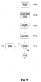
- FIG. 17 is a flow chart of a second example of the process of updating a measuring device.
- FIG. 1 An example of apparatus suitable for performing an analysis of a subject's impedance will now be described with reference to FIG. 1 .
- the apparatus includes a measuring device 1 including a processing system 2 coupled to a signal generator 11 and a sensor 12 .
- the signal generator 11 and the sensor 12 are coupled to respective electrodes 13 , 14 , 15 , 16 , provided on a subject S, via leads L, as shown.
- An optional external interface 23 can be used to couple the measuring device 1 to one or more peripheral devices 4 , such as an external database or computer system, barcode scanner, or the like.
- the processing system 2 is adapted to generate control signals, which causes the signal generator 11 to generate one or more alternating signals, such as voltage or current signals, which can be applied to a subject S, via the electrodes 13 , 14 .
- the sensor 12 determines the voltage across or current through the subject S, using the electrodes 15 , 16 and transfers appropriate signals to the processing system 2 .
- the processing system 2 may be any form of processing system which is suitable for generating appropriate control signals and interpreting an indication of the measured signals to thereby determine the subject's bioelectrical impedance, and optionally determine other information such as the cardiac parameters, presence absence or degree of oedema, or the like.
- the processing system 2 may therefore be a suitably programmed computer system, such as a laptop, desktop, PDA, smart phone or the like.
- the processing system 2 may be formed from specialised hardware.
- the I/O device may be of any suitable form such as a touch screen, a keypad and display, or the like.
- the processing system 2 , the signal generator 11 and the sensor 12 may be integrated into a common housing and therefore form an integrated device.
- the processing system 2 may be connected to the signal generator 11 and the sensor 12 via wired or wireless connections. This allows the processing system 2 to be provided remotely to the signal generator 11 and the sensor 12 .
- the signal generator 11 and the sensor 12 may be provided in a unit near, or worn by the subject S, whilst the processing system 2 is situated remotely to the subject S.
- the outer pair of electrodes 13 , 14 are placed on the thoracic and neck region of the subject S.
- the electrodes would typically be positioned on the limbs, as required.
- an alternating signal is applied to the subject S. This may be performed either by applying an alternating signal at a plurality of frequencies simultaneously, or by applying a number of alternating signals at different frequencies sequentially.
- the frequency range of the applied signals may also depend on the analysis being performed.
- the applied signal is a frequency rich current from a current source clamped, or otherwise limited, so it does not exceed the maximum allowable subject auxiliary current.
- voltage signals may be applied, with a current induced in the subject being measured.
- the signal can either be constant current, impulse function or a constant voltage signal where the current is measured so it does not exceed the maximum allowable subject auxiliary current.
- a potential difference and/or current are measured between an inner pair of electrodes 15 , 16 .
- the acquired signal and the measured signal will be a superposition of potentials generated by the human body, such as the ECG, and potentials generated by the applied current.
- the distance between the inner pair of electrodes may be measured and recorded.
- other parameters relating to the subject may be recorded, such as the height, weight, age, sex, health status, any interventions and the date and time on which they occurred.
- Other information, such as current medication, may also be recorded.
- buffer circuits may be placed in connectors that are used to connect the voltage sensing electrodes 15 to the leads L. This ensures accurate sensing of the voltage response of the subject S, and in particular helps eliminate contributions to the measured voltage due to the response of the leads L, and reduce signal loss.
- a further option is for the voltage to be measured differentially, meaning that the sensor used to measure the potential at each electrode 15 , 16 only needs to measure half of the potential as compared to a single ended system.
- the current measurement system may also have buffers placed in the connectors between the electrodes 13 , 14 and the leads L.
- current can also be driven or sourced through the subject S symmetrically, which again greatly reduced the parasitic capacitances by halving the common-mode current.
- Another particular advantage of using a symmetrical system is that the micro-electronics built into the connectors for each electrode 13 , 14 also removes parasitic capacitances that arise when the subject S, and hence the leads L move.
- the acquired signal is demodulated to obtain the impedance of the system at the applied frequencies.
- One suitable method for demodulation of superposed frequencies is to use a Fast Fourier Transform (FFT) algorithm to transform the time domain data to the frequency domain. This is typically used when the applied current signal is a superposition of applied frequencies.
- FFT Fast Fourier Transform
- Another technique not requiring windowing of the measured signal is a sliding window FFT.
- the applied current signals are formed from a sweep of different frequencies, then it is more typical to use a processing technique such as multiplying the measured signal with a reference sine wave and cosine wave derived from the signal generator, or with measured sine and cosine waves, and integrating over a whole number of cycles. This process rejects any harmonic responses and significantly reduces random noise.
- Impedance or admittance measurements are determined from the signals at each frequency by comparing the recorded voltage and current signal.
- the demodulation algorithm will produce an amplitude and phase signal at each frequency.
- the processing system 2 operates to generate control signals which are provided to the signal generator 11 at step 110 , thereby causing the signal generator to apply an alternating current signal to the subject S, at step 120 .
- the signal is applied at each of a number of frequencies f i to allow multiple frequency analysis to be performed.
- the sensor 12 senses voltage signals across the subject S.
- the measuring device operates to digitise and sample the voltage and current signals across the subject 5 , allowing these to be used to determine instantaneous bioimpedance values for the subject S at step 150 .
- the processing system 2 includes a first processing system 10 having a processor 20 , a memory 21 , an input/output (I/O) device 22 , and an external interface 23 , coupled together via a bus 24 .
- the processing system 2 also includes a second processing system 17 , in the form of a processing module.
- a controller 19 such as a micrologic controller, may also be provided to control activation of the first and second processing systems 10 , 17 .
- the first processing system 10 controls the operation of the second processing system 17 to allow different impedance measurement procedures to be implemented, whilst the second processing system 17 performs specific processing tasks, to thereby reduce processing requirements on the first processing system 10 .
- the generation of the control signals, as well as the processing to determine instantaneous impedance values is performed by the second processing system 17 , which may therefore be formed from custom hardware, or the like.
- the second processing system 17 is formed from a Field Programmable Gate Array (FPGA), although any suitable processing module, such as a magnetologic module, may be used.
- FPGA Field Programmable Gate Array
- first and second processing systems 10 , 17 , and the controller 19 are typically controlled using one or more sets of appropriate instructions. These could be in any suitable form, and may therefore include, software, firmware, embedded systems, or the like.
- the controller 19 typically operates to detect activation of the measuring device through the use of an on/off switch (not shown). Once the controller detects device activation, the controller 19 executes predefined instructions, which in turn causes activation of the first and second processing systems 10 , 17 , including controlling the supply of power to the processing systems as required.
- the first processing system 10 can then operate to control the instructions, such as the firmware, implemented by the second processing system 17 , which in turn alters the operation of the second processing system 17 . Additionally, the first processing system 10 can operate to analyse impedance determined by the second processing system 17 , to allow biological parameters to be determined. Accordingly, the first processing system 10 may be formed from custom hardware or the like, executing appropriate applications software to allow the processes described in more detail below to be implemented.
- the second processing system 17 includes a PCI bridge 31 coupled to programmable module 36 and a bus 35 , as shown.
- the bus 35 is in turn coupled to processing modules 32 , 33 , 34 , which interface with ADCs (Analogue to Digital Converters) 37 , 38 , and a DAC (Digital to Analogue Converter) 39 , respectively.
- ADCs Analogue to Digital Converters
- DAC Digital to Analogue Converter
- the programmable module 36 is formed from programmable hardware, the operation of which is controlled using the instructions, which are typically downloaded from the first processing system 10 .
- the firmware that specifies the configuration of hardware 36 may reside in flash memory (not shown), in the memory 21 , or may be downloaded from an external source via the external interface 23 .
- the instructions may be stored within inbuilt memory on the second processing system 17 .
- the first processing system 10 typically selects firmware for implementation, before causing this to be implemented by the second processing system 17 . This may be achieved to allow selective activation of functions encoded within the firmware, and can be performed for example using configuration data, such as a configuration file, or instructions representing applications software or firmware, or the like, as will be described in more detail below.
- this allows the first processing system 10 to be used to control operation of the second processing system 17 to allow predetermined current sequences to be applied to the subject S.
- different firmware would be utilised if the current signal is to be used to analyse the impedance at a number of frequencies simultaneously, for example, by using a current signal formed from a number of superposed frequencies, as compared to the use of current signals applied at different frequencies sequentially.
- FIGS. 6A to 6C An example of operation of the apparatus will now be described with reference to FIGS. 6A to 6C .
- an operator selects an impedance measurement type using the first processing system 10 .
- This may be achieved in a number of ways and will typically involve having the first processing system 10 store a number of different profiles, each of which corresponds to a respective impedance measurement protocol.
- the profile will typically be stored in the memory 21 , or alternatively may be downloaded from flash memory (not shown), or via the external interface 23 .
- this will cause the first processing system 10 to load desired code module firmware into the programmable module 36 of the second processing system 17 at step 210 , or cause embedded firmware to be activated.
- code module used will depend on the preferred implementation, and in one example this is formed from a wishbone code module, although this is not essential.
- the second processing system 17 is used to generate a sequence of digital control signals, which are transferred to the DAC 39 at step 230 .
- This is typically achieved using the processing module 34 , by having the module generate a predetermined sequence of signals based on the selected impedance measurement profile. This can therefore be achieved by having the second processing system 17 program the processing module 34 to cause the module to generate the required signals.
- the DAC 39 converts the digital control signals into analogue control signals I + , I ⁇ which are then applied to the current source 11 at step 240 .
- the current source circuit operates to amplify and filter the electrical control signals I + , I ⁇ at step 250 , applying the resulting current signals to the electrodes 13 , 14 at step 260 .
- the current circuit through the subject can optionally be shorted at step 270 , using a switch SW, to thereby discharge any residual field in the subject S, prior to readings being made.
- the measurement procedure commences, with the voltage across the subject being sensed from the electrodes 15 , 16 .
- the voltage across the electrodes is filtered and amplified using the buffer circuit shown in FIG. 5 at step 290 , with the resultant analogue voltage signals V being supplied to the ADC 37 and digitised at step 300 .
- the current applied to the subject S is detected with the analogue current signals I being digitised using the ADC 38 at step 320 .
- the digitised voltage and current signals V, I are received by the processing modules 32 , 33 at step 330 , with these being used to performed preliminary processing of the signals at step 340 .
- the processing performed will again depend on the impedance measurement profile, and the consequent configuration of the processing modules 32 , 33 .
- This can include for example, processing the voltage signals V to extract ECG signals.
- the signals will also typically be filtered to ensure that only signals at the applied frequencies f i , are used in impedance determination. This helps reduce the effects of noise, as well as reducing the amount of processing required.
- the second processing system 17 uses the processing signals to determine voltage and current signals at each applied frequency with these being used at step 360 to determine instantaneous impedance values at each applied frequency f i .
- the ADCs 37 , 38 and the processing modules 32 , 33 are typically adapted to perform sampling and processing of the voltage and current signals V, I in parallel so that the voltage induced at the corresponding applied current are analysed simultaneously. This reduces processing requirements by avoiding the need to determine which voltage signals were measured at which applied frequency. This is achieved by having the processing modules 32 , 33 sample the digitised signals received from the ADCs 37 , 38 , using a common clock signal generated by the processing module 36 , which thereby ensures synchronisation of the signal sampling.
- the instantaneous impedance values can undergo further processing in either the first processing system 10 , or the second processing system 17 , at step 370 .
- the processing of the instantaneous impedance signals will be performed in a number of different manners depending on the type of analysis to be used and this in turn will depend on the selection made by the operator at step 200 .
- the FPGA operates to generate a sequence of appropriate control signals I + , I ⁇ , which are applied to the subject S using the signal generator 11 .
- the voltage induced across the subject is then sensed using the sensor 12 , allowing the impedance values to be determined and analysed by the second processing system 17 .
- Using the second processing system 17 allows the majority of processing to be performed using custom configured hardware. This has a number of benefits.
- a second processing system 17 allows the custom hardware configuration to be adapted through the use of appropriate firmware. This in turn allows a single measuring device to be used to perform a range of different types of analysis.
- this vastly reduces the processing requirements on the first processing system 10 .
- This allows the first processing system 10 to be implemented using relatively straightforward hardware, whilst still allowing the measuring device to perform sufficient analysis to provide interpretation of the impedance.
- This can include for example generating a “Wessel” plot, using the impedance values to determine parameters relating to cardiac function, as well as determining the presence or absence of lymphoedema.
- the measuring device 1 can be updated.
- the measuring device can be updated by downloading new firmware via flash memory (not shown) or the external interface 23 .
- processing is performed partially by the second processing system 17 , and partially by the first processing system 10 .
- processing it is also possible for processing to be performed by a single element, such as an FPGA, or a more generalised processing system.
- the FPGA is a custom processing system, it tends to be more efficient in operation than a more generic processing system. As a result, if an FPGA alone is used, it is generally possible to use a reduced overall amount of processing, allowing for a reduction in power consumption and size. However, the degree of flexibility, and in particular, the range of processing and analysis of the impedance which can be performed is limited.
- the above described example strikes a balance, providing custom processing in the form of an FPGA to perform partial processing. This can allow for example, the impedance values to be determined. Subsequent analysis, which generally requires a greater degree of flexibility can then be implemented with the generic processing system.
- a further disadvantage of utilising an FPGA alone is that it complicates the process of updating the processing, for example, if improved processing algorithms are implemented.
- an operator of the apparatus provides details of a type of impedance measurement to be performed.
- the operator positions electrodes on the subject before connecting leads to the electrodes based on connection instructions provided by the apparatus at step 520 .
- This process will therefore typically involve having the operator place a number of electrodes on the subject and then connecting leads to selected ones of the electrodes based on the particular measurement being performed.
- the measuring device 1 will operate to perform impedance measurements by generating an appropriate current sequence and applying this to the subject via the electrodes 13 , 14 .
- the measuring device 1 determines if further impedance measurements are required and if so the process returns to step 520 to allow the operator to connect leads to different ones of the electrodes as required. This process is repeated until sufficient impedance measurements have been collected to perform the required analysis.
- step 550 the process moves on to step 550 with the measuring device 1 operating to process the impedance measurements and provide an indication of required information to the operator.
- this may be achieved in a number of ways and that typically, this involves having the operator select a predetermined impedance measurement procedure and then follow instructions provided by the measuring device 1 to allow the impedance measurements to be correctly collected.
- FIGS. 6A and 6B describe the process of collecting impedance data.
- the operator activates the measuring device 1 causing the first processing system 10 to determine a list of the available measurement types.
- the available measurement types will be determined either from the memory 21 , or alternatively downloaded via the external interface 23 and are based on predetermined profiles which provide suitable instructions to allow the measuring device 1 to perform the required impedance measurements.
- the profiles will depend for example on factors such as the type of impedance measurements to be performed, or the like.
- the profile will be different for cardiac parameter determination as compared to oedema detection.
- the first processing system 10 will display a list of available measurement types to the operator utilising a suitable GUI.
- the operator selects an appropriate one of the measurement types. This causes the first processing system 10 to access the corresponding profile and determine if any additional information is required, such as body parameters including age, weight, sex, an indication of body segments, such as limbs to be analysed, or the like.
- the first processing system 10 can be adapted to assist the operator in selecting the correct measurement type.
- the particular measurement that should be made may depend on a number of factors, such as the body parameters, as well as whether any interventions have occurred.
- the operator can provide details of the body parameters, interventions, or the like.
- the first processing system 10 can then uses these to access details of available measurement types and determine the preferred measurement type for the given situation.
- the first processing system 10 may access an LUT (look-up table) that specifies the measurement profile that should be used in different circumstances.
- LUT look-up table
- the relationships in the LUT can be defined by medically qualified personnel, thereby removing the requirement on the operator to make a medical decision.
- rules may be provided in the profiles, so that the first processing system 10 is only able to access profiles that are suitable for the current body parameter and intervention status.
- Rules can alternatively be derived using heuristic algorithms based on selections made by medically qualified operators during measurement procedures. It will be appreciated that in this instance, as the device is used, the first processing system 10 will collate information regarding the body parameters and intervention status of the subject and the measurement profile selected, and use this to derive rules used in future profile selection. Such heuristic algorithms are known in the art and will not be described in any further detail.
- these techniques allow different measurement profiles to be selected based on factors such as the age, height, weight, race, sex or the like, of the subject, as well as the current intervention status.
- a further feature that can be implemented is to allow the first processing system 10 to access one or more remote databases, which may form one of the peripheral devices 4 , to determined information regarding the subject. This can include information such as the body parameters, and details of any interventions or the like.
- a search database option allowing the subject information to be retrieved. This is typically performed on the basis of a subject identifier, such as a unique number assigned to the individual upon admission to a medical institution, or may alternatively be performed on the basis of name or the like.
- a database is generally in the form of an HL7 compliant remote database, although any suitable database may be used.
- the subject can be provided with a wristband or the like which includes coded data indicative of the subject identifier.
- the measuring device 1 can be coupled to a peripheral device 4 for determining the subject identifier.
- the data may be in the form of a barcode, with the peripheral device 4 being a barcode scanner.
- RFID Radio Frequency ID
- the barcode reader detects the barcode provided on the subject's wrist band, and determines a subject identifier from the detected barcode.
- the barcode reader provides data indicative of the sensed subject identifier to the first processing system 10 , thereby allowing the first processing system 10 to access the subject record from the database as described above.
- the first processing system 10 displays an indication of the required information, or an appropriate database search screen at step 610 , allowing the operator to provide or retrieve subject information at step 615 .
- the first processing system 10 operates to determine a measurement procedure at step 620 .
- the measurement procedure will be determined from the profile and is typically in the form of a sequence of measurements that need to be made.
- the profile will also include an indication of electrode placements for each of the measurements, together with details of the required current sequence that must be applied to each electrode configuration in order for the necessary measurements to be collected.
- the first processing system 10 displays an indication of the required electrode positions allowing the operator to position the electrodes on the subject at step 630 .
- the first processing system 10 determines and displays an indication of a lead connection.
- the lead connection represents the next body segment to be measured and this is achieved utilising a suitable representation described in more detail below.
- this may be achieved using four leads corresponding to two current leads, and two voltage leads, with each lead having a respective colour.
- the display highlights particular electrode positions in an appropriate colour thereby allowing the operator to connect each lead to the corresponding electrode at step 640 .
- the first processing system 10 determines a current sequence which is to be applied to the subject and causes this to be generated utilising the processing module, which in this example is an second processing system 17 .
- the operation of the second processing system 17 can be controlled using instructions provided by the first processing system 10 .
- the instructions could be in any one of a number of forms, and may correspond to firmware, embedded systems, software, or the like. In the event that firmware is used, this may be either provided by the first processing system 10 , or retrieved from an internal or external memory by the second processing system 17 as required, based on instructions from the first processing system 10 .
- the instructions specify the configuration of the second processing system 17 thereby allowing the impedance measurements to be correctly made and subsequently analysed. It will therefore be appreciated that the instructions will depend on the selected impedance measurement profile selected above. It will be appreciated that if firmware is used, this may reside in flash memory (not shown), in the memory 21 , or may be downloaded from an external source via the external interface 23 .
- the second processing system 17 measures the current through and/or voltage across the electrodes for each of the applied current frequencies f t before confirming that the measurement is completed at step 650 .
- the measuring device 1 operates to determine if further measurements are required at step 655 . In the event that further measurements are required the process returns to step 635 to allow the measurements to be performed.
- processing of the impedance measurements is performed based on the selected measurement type.
- the analysis may be performed either in the first processing system 10 , or the second processing system 17 , or in a combination of the second processing system 17 or the first processing system 10 , depending on the preferred implementation.
- the software implemented by the first processing system 10 , or the firmware used by the second processing system 17 will typically be selected based on selected impedance measurement type and will therefore be indicated in the impedance measurement profile.
- the operator need only select a respective profile to perform an impedance measurement and obtain a result.
- the first processing system 10 uses the selected profile to determine the sequence of measurements that need to be performed, operates to instruct the operator in locating the electrodes and then connecting these in the necessary sequence.
- the first processing system 10 can also determine from the profile, the software and/or firmware which is needed to perform the analysis, allowing this to be downloaded into the first processing system 10 and/or the second processing system 17 as required. Consequently, the measuring device 1 can automatically determine the required processing to be performed on the impedance measurements, allowing a result to be presented directly to the operator, thereby obviating the need for the operator to provide any input during the process.
- oedema is a build-up of fluid in a particular limb. Accordingly, in this example, by measuring the impedance of the limb it is possible to determine information regarding fluid levels and hence determine the presence or absence of oedema.
- oedema typically occurs after an injury has occurred or surgery has been performed. Accordingly, if it is possible to perform a measurement of the limb prior to surgery, analysis of the impedance after surgery can be used to detect the onset of oedema. However, if no such measurement has been made, it is necessary to use an alternative reference to determine whether the current fluid levels are indicative of the presence of oedema.
- FIGS. 7A to 7C An example of the process for allowing oedema measurements to be made will now be described with reference to the flowchart shown in FIGS. 7A to 7C and with reference to the graphical user interface (GUI) screen shots shown in FIGS. 8 , 9 , 10 and 11 .
- GUI graphical user interface
- an operator of the monitoring device 1 views available measurement profiles displayed by the measuring device 1 .
- the operator selects a peripheral oedema measurement, with the first processing system 10 operating to select an appropriate oedema measurement profile, typically from the memory 21 , at step 710 .
- the first processing system 10 may download appropriate firmware into the second processing system 17 , allowing the correct current sequences to be generated, and the measured potentials to be analysed.
- the measuring device 1 displays a GUI 1000 as shown in FIG. 8A .
- the GUI includes a number of fields, shown generally at 1001 , which allow data regarding the individual to be provided.
- the data includes name information such as name, address, sex, height, weight or the like. Additionally, an indication of the limbs at risk from oedema can be input as shown at 1002 .
- the subject record is typically stored in a subject database accessed via the external interface 23 , or the like.
- the subject record includes the subject data, and details of any performed impedance measurements for the respective subject, thereby allowing the subject record to form a subject history for use in longitudinal analysis.
- the operator can perform a search to retrieve the record from the database.
- the database is typically a HL7 compliant remote database, and it will therefore be appreciated that the database may be the same database from which the subject details are retrieved, as described above with respect to step 705 .
- the processing system will update the GUI 1000 at step 720 , as shown in FIG. 8B to display any previously measured impedance values, which may be used as reference data, as will be described in more detail below. Searching, editing and creation of records using the input controls shown generally at 1004 .
- the first processing system 10 generates a GUI 1010 , an example of which is shown in FIG. 9A , and which is used in allowing the operator to provide electrode connections.
- the GUI 1010 includes an indication of subject details at 1011 .
- a representation 1012 of the subject is provided, which shows general electrode connection points 1012 A, indicating where on the subject electrodes should be provided.
- the general arrangement is to provide electrodes on the hand at the base of the knuckles and between the bony protuberances of the wrist, as shown in FIG. 9B , and on the feet at the base of the toes and at the front of the ankle, as shown in FIG. 9C .
- the GUI 1010 also displays details for each limb at 1017 A, 1017 B, 1017 C, 1017 D, including an indication of whether the limb is an at risk limb. This is also shown on the representation 1012 at 1017 E.
- An instruction field is shown generally at 1018 is provided to display instructions to the operator, with an indication of the selected measurement procedure being shown at 1019 , and general measuring device status information being provided at 1020 .
- a comments field 1021 can also be used to record comments regarding the measurements made.
- the operator typically updates the weight of the subject in the subject details 1011 , which may undergo significant variations over time due to changes in fluid levels within the subject's body.
- the operator may also respecify the at risk limbs, which is useful when a subject develops further lymphoedema. For example, a subject may start off with unilateral lymphoedema of the left leg and over time may develop a lymphoedema in the right leg. This leg can be recorded at that point as being affected by the use of the “at risk” check boxes.
- the measurement procedure can be initiated by clicking the “ok button” 1022 .
- both the weight and comments for each measurement are recorded as part of the corresponding subject record in the subject database. This allows the practitioner to track weight and clinical comments over the period of measurement.
- the electrode-lead placement GUI 1010 is updated as shown in FIG. 9D to direct the operator to connect the leads from the measuring device 1 the electrodes.
- the representation 1012 indicates which of the electrodes should be connected to the monitoring apparatus, as shown at 1013 , 1014 , 1015 , 1016 , to thereby form the current electrodes 13 , 14 , and the voltage electrodes 15 , 16 .
- This is achieved using colour coding, by using leads having colours corresponding to those shown on the representation, thereby ensure that each electrode is correctly connected to the measuring device 1 .
- the representation 1012 shows the electrode configuration required to measure the impedance in the right arm.
- this configuration uses the theory of equal potentials, allowing the electrode positions to provide reproducible results for impedance measurements. For example when current is injected between electrodes 1013 and 1016 in FIG. 9D , electrode 1014 could be placed anywhere along the left arm, since the whole arm is at an equal potential. This is advantageous as it greatly reduces the variations in measurements caused by poor placement of the electrodes by the operator. It also greatly reduces the number of electrodes required to perform segmental body measurements, as well as allowing the limited connections shown to be used to measure each of limbs separately.
- the operator uses a measure button 1023 to cause the measuring device 1 to perform the impedance measurement, with general measuring device status information being provided at 1020 .
- the first processing system 10 determines from the profile, the next measurement to be performed, and generates the GUI including appropriate information in the representation 1012 and the instruction field 1018 .
- the operator connects electrodes in accordance with the electrode connections shown on the representation 1012 , and once this has been completed selects the measurement button 1023 , causing the measurement to be performed.
- the monitoring device 1 generates the required current signal(s), and applies these to the subject, before measuring the current and voltage across the subject at step 735 , to allow instantaneous impedance values to be determined at a number of different frequencies f i .
- step 740 it is determined if further measurements are required. If so, the measuring device 1 operates to update the GUI 1010 , at step 745 , based on the next measurement to be performed, as shown for example, in FIG. 9E .
- the representation 1012 is updated to show the next required electrode connections 1013 , 1014 , 1015 , 1016 , which in this case correspond to performing measurements on the right leg. Additionally, the first processing system 10 will also display preliminary results from the completed measurement. Thus, in this example, as the right arm has already been measured, an impedance parameter indication is shown at 1017 A, in FIG. 9E .
- Steps 730 to 745 are then repeated as required, which in this case involves performing at least four sets of measurements, one for each limb, as shown in FIGS. 9F and 9G .
- step 750 with the monitoring device updating the GUI 1010 to indicate that the measurement process is completed 1018 , and that the measurements can be saved using the button 1024 , as shown in FIG. 9H .
- the first processing system 10 can update the GUI 1000 to reflect the saved measurements as shown in FIG. 9I , at step 755 .
- the operator can review the measured impedances as well as analysing the impedances to determine the onset of oedema.
- the operator selects raw impedance data display.
- the first processing system 10 displays the raw impedance parameters utilising a GUI 1030 .
- the GUI includes subject details at 1031 , and a measurement selection inputs 1032 . This allows the operator to select measurements of interest, which in this example includes measurements from the left arm.
- the first processing system 10 displays an overview of parameters determined from the impedance measurements at 1033 .
- the parameters derived will depend on the analysis being performed and will typically include parameters such as the impedance at zero, characteristic and infinite frequencies (R 0 , Z c , R ⁇ ). These can be derived based on the impedance response of the subject, which at a first level can be modelled using the equation (1), known as the Cole model, in which:
- ⁇ has a value between 0 and 1 and can be thought of as an indicator of the deviation of a real system from the ideal model.
- the value of the impedance parameters R 0 and R ⁇ may be determined in any one of a number of manners such as by:
- the first processing system 10 can also be adapted to test adherence of the measurements to the Cole model.
- the Cole model assumes that the impedance measurements lie on a semi-circular impedance locus. Accordingly, the first processing system 10 can determine if the measured values fit a semi-circular locus to thereby determine if the Cole model is satisfied.
- the measured impedance parameter values can be compared to theoretical values derived using the equation (2), to thereby allow the degree of concordance to the Cole model to be determined.
- a number of tabs 1034 can be used to allow different representations of the measured impedance values to be provided in a window 1035 .
- the impedance values can be listed as shown in FIG. 10B , or plotted as reactance verses frequency or resistance verses frequency as shown in FIGS. 10C and 10D respectively.
- Frequency controls 1036 are provided to allow impedance measurements above or below threshold limits to be omitted from the displayed results, as shown by threshold markers 1037 A, 1037 B. Additionally a rejection limit can be applied to discard data points that fall outside a threshold variation from an idealised semi-circular locus provided on the “Wessel” plot.
- the operator selects any references to be used.
- the reference will typically be in the form of earlier data collected for the respective subject, thereby allowing a longitudinal analysis to be performed.
- the system may also or alternatively use a normal population database table, which includes reference values obtained from different subjects.
- This database table is essentially a single subject database table into which all measurements of normal population subjects (people without lymphoedema) are added.
- FIG. 11A An example of such normal population data displayed using the GUI 1000 is shown in FIG. 11A .
- This table then acts as a pool of data from which normalised values for raw impedance data and ratios of impedance data can be generated, allowing comparison with measured values for the subject to be performed.
- This generation of this normalised data is in the form of mean (averaged) values that are selected to be relevant to the test subject.
- the selection is performed based on the subject information and may be performed on the basis of any one of a number of factors, such as age, sex, height, weight, race, interventions, or the like.
- test subject has unilateral lymphoedema of the dominant arm and is female then the normalised data drawn from the normal population database will be calculated from the dominant arm measurements from female subjects that are present in the in the normal population database.
- step 775 the operator is presented with a GUI 1040 similar to that shown in FIG. 11A , which allows the operator to select appropriate records from the normal population table, as shown by the highlighted entry at 1041 .
- this is generally achieved by ensuring measurements taken prior to surgery or events that put them at risk of developing lymphoedema.
- a common example is baseline measurements taken before surgical intervention for breast cancer that can be use to track subjects fluid shifts post surgery by comparison of study measurements to these baseline generated mean values.
- Subject specific baselines can be generated automatically from measurements in the subject's database table. This can be achieved using the GUI 1000 shown in FIG. 11B , in which the subject's record is displayed. Located on the GUI 1000 are two selection windows 1042 , 1043 that are used to define the measurements used from the subject's database table to generate mean data values for comparison to study measurements.
- the process can also be used to add data to the normal population table. This is achieved by performing the measurement process outlined above, and in the event that the subject does not suffer from oedema, for example if surgery has not yet been performed, importing the data into the normal population table. This can be performed in addition to adding the measurements to the subject record, so that measurements collected from a healthy individual can be used for subsequent longitudinal analysis and/or as a normal population reference.
- the measuring device 1 determines if a reference is available, and if so, the first processing system 10 compares the currently determined parameters to one or more reference values at step 795 , and utilises this to generate reports which are displayed at step 800 .
- the first processing system 10 can analyse the impedance of contra-lateral limbs at step 785 and provide an appropriate output at step 800 . This may be achieved for example by determining an index based on a ratio of the extra- to intra-cellular fluid levels in each leg, and then comparing the values determined to assess whether there is difference between the limbs, and hence whether there is a likelihood of oedema being present.
- the extracellular fluid resistance R e is determined from:
- R i R ⁇ ⁇ R e R e - R ⁇
- the first processing system 10 typically determines the index for each limb. A ratio of the determined index for different pairs of limbs are then compared at step 790 , thereby allowing the operator to determine if there is a likelihood of bilateral oedema.
- the report is presented using a GUI 1050 that includes subject details shown generally at 1051 .
- the GUI includes controls 1052 that allow the operator to select whether reference data is to be used and the nature of the reference data.
- the process will return to step 540 to reassess the nature of the output dependent on the type of reference selected.
- a drop down list is provided to indicate the nature of the parameter that is to be displayed
- checkboxes are provided indicating the limbs for which the parameter is to be displayed.
- a limb of interest and a reference limb can be selected using the check boxes 1054 , 1055 as shown.
- the parameters available for charting include:
- the lymphogram or impedance vector plot is a graphical representation of when a subject's measurements move relative to a reference ellipse.
- the reference ellipse can be generated from a 95% confidence interval based on the subject specific baseline data or the normal population data.
- data points of a study body segment move outside the ellipse the subject's condition is worsening and lymphoedema is present in that body segment.
- the ellipse can be generated for and displayed for each body segment chosen using the reference limb checkbox.
- the data points displayed are those generated from the study body segment data for the subject.
- the study body segments and reference body segments are chosen using the body segment selector check boxes located underneath the chart.
- FIG. 11C shows an example of a lymphogram in which the index for left and right legs is compared.
- the index remains within the ellipse shown generally at 1056 highlighting that lymphoedema is not present.
- the right arm and left arm are compared as shown in FIG. 11D , the values for the ratio comparisons fall outside the reference ellipse 1056 indicating that the right arm is suffering from oedema.
- the lymphogram includes a comparison between limbs, and accordingly, the checkboxes 1053 B are not used.
- FIG. 11E is an example of the ratio of limb ratios in which a ratio of the index for the right arm and right legs is plotted against time. In this instance, it can be seen that a significant variation is present at 1057 indicating the likelihood of oedema.
- checkboxes 1053 B are not used, and are ignored.
- This function will display the ratio of the R 0 of the reference body segment divided by that of a study body segment for each measurement in the subject's database table.
- the index I can also be displayed for each body segment for all measurements in the subject's database table as a chart over time, as shown in FIG. 11F .
- the body segments represented on the chart are selected using the control 1053 .
- the 1054 , 1055 are omitted for clarity.
- the value of R 0 can also displayed for each body segment for all measurements in the subjects database table as a chart over time.
- the value of R ⁇ can also displayed for each body segment for all measurements in the subjects database table as a chart over time.
- the value of R i can also displayed for each body segment for all measurements in the subjects database table as a chart over time.
- the characteristic frequency can also displayed for each body segment for all measurements in the subjects database table as a chart over time.
- SEE standard estimate of errors
- the value of the time delay (Td) associated with each measurement can also displayed for each body segment for all measurements in the subjects database table as a chart over time.
- reference values can also be displayed based either on the normalised population reference or subject specific reference.
- FIG. 11F An example of the use of a subject's specific reference value is shown in FIG. 11F .
- the reference value is based on R 0 as shown at 1058 . Accordingly, it can be seen that variation of the value R 0 compared to the reference is indicative of oedema.
- the generation of a report by comparison to normal population data will be performed in a similar manner.
- a further feature of the process is the ability to associate event markers with specific measurements in the measurement database table.
- Event markers can provide commented time points that correspond to measurements and points in time. These can be customised by the user to indicate important events that need to be documented on the longitudinal analysis charts. Such events may include, onset date of lymphoedema, the start of massage intervention etc. These markers will be displayed automatically on the longitudinal charts that are a function over time. Event markers can also be shown on charts as shown for example in FIG. 11H .
- the first processing system 10 therefore selects the types of analysis or representation that is most appropriate for determining the presence or absence of oedema based on the currently available data. This therefore removes the requirement for the operator to make an assessment of which form of report would provide the most accurate indication of the onset of oedema.
- the impedance measurements are collected for each of the limbs, with the assessment of the preferred type of analysis being performed after the measurements have been performed.
- the first processing system 10 can be adapted to determine the preferred type of analysis first and then only perform the measurements required in order for the type of analysis to be performed.
- a limited limb analysis can be performed, in which the operator specifies the limbs for which measurements are to be made prior to the measurement process. In this instance, data will only be collected for the limbs of interest.
- profiles can be configured to allow a range of different measurements to be performed.
- TBW total body water
- the volumes of extracellular and intracellular fluid can be derived from the values R 0 , R ⁇ , as these depend on the values of the extracellular and intracellular resistance, as discussed above.
- the TBW can be used in:
- measurement profiles can be determined to allow measurement of:
- a base station 1300 is coupled to a number of measuring devices 1 , and a number of end stations 1303 via a communications network 1302 , such as the Internet, and/or via communications networks 1304 , such as local area networks (LANs), or wide area networks (WANs).
- the end stations 1303 may also be coupled to measuring devices 1 , as shown.
- the end station 1303 may be any form of end station but is typically a desktop, laptop, tablet, PDA, Smart Phone or the like.
- the base station 1300 includes a processing system 1310 , coupled to a database 1311 . This allows the base station 1300 to be used to update the measuring devices 1 , as will be described in more detail below.
- the measuring devices 1 can be connected via the external interface 23 , directly to the end stations 1303 , or via one of the networks 1302 , 3104 . This may be achieved via a wired, or wireless connection, depending on the nature of the external interface 23 , the end stations 1303 , and the networks 1302 , 1304 .
- the end station 1303 can be used to control the measuring device 1 to perform the measurement procedure.
- the measuring device 1 therefore operates to generate required excitation signals, apply these to the subject, and measure the resulting voltages generated across the subject. Once impedance measurements have been collected, these are transferred via the external interface 23 to the end station 1303 , which operates to analyse the measured impedance values and generate the appropriate GUIs shown in FIGS. 8 to 11 .
- the operator of the system is generally required to place the measuring device 1 in a predetermined operating mode allowing the end station 1303 to generate any required control signals to activate the measurement process.
- the measuring device 1 will therefore typically operate to perform single measurements at a given time.
- the end station 1303 will display the next electrode configuration to be used to the operator.
- the operator will connect the electrodes, 13 , 14 , 15 , 16 to the subject, in the displayed arrangement, and then indicate to the end station 1303 when this has been completed.
- the end station 1303 will then transfer a control signal to the measuring device 1 causing the next measurement to be performed.
- the end station 1303 can implement a measurement-halt check. During this process if the end station 1303 detects measurements within a predetermined time interval, such as 5 seconds, the end station 1303 generates an alert indicating that the measuring device 1 is not provided in single measurement mode, and that this should be adjusted.
- a predetermined time interval such as 5 seconds
- the end station 1303 can effectively perform the tasks performed by the first processing system 10 in the examples throughout the specification. Accordingly, the device could be provided without the first processing system 10 , with the functionality usually performed by the first processing system 10 being performed by an end station 1303 . In this arrangement, the end station 1303 therefore effectively forms part or all of the first processing system 10 . This allows the measuring device 1 to be provided including only the second processing system 17 coupled directly to the external interface 23 to allow the measuring device 1 to be controlled by the end station 1303 . This would typically be achieved via the use of suitable applications software installed on the end station 1303 .
- communication between the end station 1303 and the measuring device 1 is typically controlled using the GUI 1060 shown in FIG. 14 .
- the GUI includes fields 1061 for defining IP connection details, which allows the end station 3 to connect to the measuring device 1 , via the external interface 23 , via a TCP/IP or other network.
- Fields 1062 are used for defining paths via which the references can be obtained, with the fields 1063 defining details of the database from which the references should be obtained.
- Fields 1064 and 1065 are used to define parameters relating to the impedance analysis to be performed, including default frequency, rejection and time delay limits, as well as reference ranges or the like. Finally fields 1066 are used to define properties of the resulting analysis report.
- GUI can also be used to provide connections to remote databases, such as HL7 compliant subject databases.
- the architecture can be implemented in any one of a number of manners depending on the circumstances in which the measuring device 1 is to be used.
- the selection and/or analysis of the impedance measurements can be performed by a central base station coupled to a number of measuring devices via a suitable communications system, such as a computer network or the like.
- a suitable communications system such as a computer network or the like.
- the base station transfers an indication of this to the respective monitoring thereby causing the measuring device 1 to display the necessary electrode connections.
- the determined measurements are returned to the base station for analysis.
- the process involves determining a measuring device 1 is to be configured with an upgrade, or the like, before configuration data is created at step 1510 .
- the configuration data is typically uploaded to the device or the end station 1303 before the device is activated at 1530 , or applications software on the end station 1303 is executed.
- the processing system 2 uses the configuration data to selectively activate features, either for example by controlling the upload of instructions, or by selectively activating instructions embedded within the processing system 2 or the controller 19 .
- Features within applications software installed on the end station 1303 can be activated in a similar manner.
- the configuration data could consist of instructions, such as a software or firmware, which when implemented by the processing system 2 causes the feature to be implemented.
- this process may be utilised to update the operation of the firmware provided in the second processing system 17 , the processing system 10 or the controller 19 to allow additional functionality, improved measuring algorithms, or the like, to be implemented.
- the configuration data could be in the form of a list of features, with this being used by the processing system 2 to access instructions already stored on the measuring device 1 .
- Configuration of configuration data in this manner allows the measuring device to be loaded with a number of as yet additional features, but non-operational features, when the device is sold.
- by updating the configuration data provided on the measuring device 1 this allows these further features to be implemented without requiring return of the measuring device 1 for modification.
- the feature receives approval for use.
- techniques may be available for measuring or detecting lymphoedema in a predetermined way, such as through the use of a particular analysis of measured voltage signals or the like.
- approval may not yet have been obtained from an administering body such as the Therapeutic Goods Administration, or the like.
- the feature is disabled by appropriate use of a configuration data.
- the configuration data can be modified by uploading a new updated configuration data to the measuring device, allowing the feature to be implemented.
- the base station 1300 includes a processing system 1310 , coupled to a database 1311 .
- the base station 1300 operates to determine when updates are required, select the devices to which updates are applied, generate the configuration data and provide this for update to the devices 1 .
- the processing system 1310 may therefore be a server or the like.
- a user's end station 1303 such as a desk top computer, lap top, Internet terminal or the like
- the communications network 1302 , 1304 such as the Internet.
- any suitable communications system can be used such as wireless links, wi-fi connections, or the like.
- the base station 1300 determines that there is a change in the regulatory status of features implemented within a certain region. As mentioned above this could occur for example following approval by the TGA of new features.
- the base station 1300 uses the change in regulatory status to determine new features available at step 1610 , before determining an identifier associated with each measuring device 1 to be updated at step 1620 .
- changes in regulatory approval are region specific, this is typically achieved by having the base station 1300 access database 1311 including details of the regions in which each measuring device sold are used.
- the database 1311 includes the identifier for each measuring device 1 , thereby allowing the identifier of each measuring device to be updated to be determined.
- the base station 1300 determines the existing configuration data, typically from the database 1311 , for a next one of the measuring devices 1 , before modifying the configuration data to implement the new features at step 1640 .
- the configuration data is then encrypted utilising a key associated with the identifier.
- the key may be formed from a unique prime number associated with the serial number, or partially derived from the serial number, and is typically stored in the database 1311 , or generated each time it is required using a predetermined algorithm.
- step 1660 the encrypted configuration data is transferred to the measuring device 1 as described above.
- the first processing system 10 determines the encryption key, and uses this to decrypt the configuration data. This may be achieved in any one of a number of ways, such as by generating the key using the serial number or other identifier, and a predetermined algorithm. Alternatively, this may be achieved by accessing a key stored in the memory 21 . It will be appreciated that any form of encryption may be used, although typically strong encryption is used, in which a secret key is used to both encrypt and decrypt the configuration data, to thereby prevent fraudulent alteration of the configuration by users, as will be explained in more detail below.
- the first processing system 10 activates software features within the second processing system 16 using the decrypted configuration data.
- this provides a mechanism for automatically updating the features available on the measuring device. This may be achieved either by having the second processing system 16 receive new firmware from the processing system 10 , or by activating firmware already installed on the second processing system 16 , as described above.
- the process can be used to allow features to be activated on payment of a fee.
- a user may purchase a measuring device 1 with limited implemented functionality. By payment of a fee, additional features can then be activated as and when required by the user.
- the first processing system 10 when the user selects an inactive feature at step 1700 , the first processing system 10 will generate an indication that the feature is unavailable at step 1710 . This allows the user to select an activate feature option at step 1720 , which typically prompts the user to provide payment details at step 1730 .
- the payment details are provided to the device manufacturer in some manner and may involve having the user phone the device manufacturer, or alternatively enter the details via a suitable payment system provided via the Internet or the like.
- step 1740 once the payment is verified, the process can move to step 1620 to allow an automatic update to be provided in the form of a suitable configuration data. However, if payment details are not verified the process ends at 1750 .
- encrypting the configuration data utilising a unique identifier means that the configuration data received by a measuring device 1 is specific to that measuring device. Accordingly, the first processing system 10 can only interpret the content of a configuration data if it is both encrypted and decrypted utilising the correct key. Accordingly, this prevents users exchanging configuration data, or attempting to re-encrypt a decrypted file for transfer to a different device.
- the configuration data it would be typical for the configuration data to include any required firmware to be uploaded, allowing this to be loaded into the second processing system 16 , using the first processing system 10 .
- This firmware can then either be automatically implemented, or implemented in accordance with the list of available features provided in the configuration data.
- this provides a mechanism for updating and/or selectively activating or deactivating features, such as measuring protocols, impedance analysis algorithms, reports interpreting measured results, or the like. This can be performed to ensure the measuring device conforms to existing TGA or FDA approvals, or the like.
- the end station 1303 can be used to download configuration data, or alternatively transfer instructions to any one of the processing systems 2 , 10 , 17 , 19 used by the measuring device 1 , to allow updating of the device operation.
- the above described processes can be used for diagnosing the presence, absence or degree of a range of conditions and illnesses, including, but not limited to oedema, lymphoedema, body composition, or the like.
Landscapes
- Health & Medical Sciences (AREA)
- Life Sciences & Earth Sciences (AREA)
- Engineering & Computer Science (AREA)
- Surgery (AREA)
- General Health & Medical Sciences (AREA)
- Biophysics (AREA)
- Pathology (AREA)
- Veterinary Medicine (AREA)
- Biomedical Technology (AREA)
- Heart & Thoracic Surgery (AREA)
- Medical Informatics (AREA)
- Molecular Biology (AREA)
- Public Health (AREA)
- Animal Behavior & Ethology (AREA)
- Physics & Mathematics (AREA)
- Nuclear Medicine, Radiotherapy & Molecular Imaging (AREA)
- Radiology & Medical Imaging (AREA)
- Physiology (AREA)
- Cardiology (AREA)
- Hematology (AREA)
- Human Computer Interaction (AREA)
- Artificial Intelligence (AREA)
- Computer Vision & Pattern Recognition (AREA)
- Psychiatry (AREA)
- Signal Processing (AREA)
- Measurement And Recording Of Electrical Phenomena And Electrical Characteristics Of The Living Body (AREA)
Abstract
A method of performing impedance measurements on a subject. The method includes using a processing system to determine at least one impedance measurement to be performed, and at one electrode arrangement associated with the determined measurement. A representation of the arrangement is displayed so the impedance measurement can be performed once the electrodes have been arranged in accordance with the displayed representation.
Description
- The present invention relates to a method and apparatus for monitoring biological parameters, and in particular to a method and apparatus for performing impedance measurements.
- The reference in this specification to any prior publication (or information derived from it), or to any matter which is known, is not, and should not be taken as an acknowledgment or admission or any form of suggestion that the prior publication (or information derived from it) or known matter forms part of the common general knowledge in the field of endeavour to which this specification relates.
- One existing technique for determining biological parameters relating to a subject, such as cardiac function, involves the use of bioelectrical impedance. This involves measuring the electrical impedance of a subject's body using a series of electrodes placed on the skin surface. Changes in electrical impedance at the body's surface are used to determine parameters, such as changes in fluid levels, associated with the cardiac cycle or oedema.
- Accordingly, complex signal processing is required to ensure measurements can be interpreted. Typically devices for achieving this utilise custom hardware configurations that are application specific. As a result, the devices can typically only be used in a limited range of circumstances.
- Lymphoedema is a condition characterised by excess protein and oedema in the tissues as a result of reduced lymphatic transport capacity and/or reduced tissue proteolytic capacity in the presence of a normal lymphatic load. Acquired, or secondary lymphoedema, is caused by damaged or blocked lymphatic vessels. “The commonest inciting events are surgery and/or radiotherapy. However, onset of lymphoedema is unpredictable and may develop within days of its cause or at any time during a period of many years after that cause.
- WO00/79255 describes a method of detection of oedema by measuring bioelectrical impedance at two different anatomical regions in the same subject at a single low frequency alternating current. The two measurements are analysed to obtain an indication of the presence of tissue oedema by comparing with data obtained from a normal population.
- Other known methods of analysis of bioelectrical impedance measurements involve determining a phase and amplitude value for the measured signals. The measurement of amplitude is straightforward but the measurement of phase is more complicated and therefore the required equipment is costly.
- In view of the different types of impedance measurement that can be performed, operators of impedance monitoring units have to be knowledgeable regarding their operation. In particular, it is necessary for the operator to know the location at which electrodes must be fitted, as well as the manner in which the electrodes must be coupled to the monitoring unit. It may also be necessary to change the connections midway through the monitoring process and this is often a difficult process.
- In some situations, machines are only adapted to provide only one form of impedance analysis and as a result, provide a standard output that must then be interpreted by the operator. However, in the event that different operating modes can be selected, it is necessary for the operator of the machine to be aware of any intricacies associated with the selected measurement mode, as well as being able to interpret the different outputs that may be available.
- In a first broad form the present invention provides a method of performing impedance measurements on a subject, the method including, in a processing system:
-
- a) determining at least one impedance measurement to be performed;
- b) determining at least one electrode arrangement associated with the determined impedance measurement;
- c) displaying a representation indicative of the electrode arrangement; and,
- d) causing the impedance measurement to be performed once the electrodes have been arranged in accordance with the displayed representation.
- Typically the method includes, in the processing system:
-
- a) receiving input commands indicating that the electrodes are arranged in accordance with the displayed arrangement; and,
- b) causing the impedance measurement to be performed in accordance with the received input command.
- Typically the representation is indicative of:
-
- a) the position of a set of electrodes; and,
- b) lead connections between the processing system and a number of the set of electrodes.
- Typically the representation includes, for each lead connection, a respective colour indication, the colour indication being indicative of a colour for a respective lead.
- Typically the method includes, in the processing system:
-
- a) determining a sequence of measurements; and,
- b) generating a sequence of representations, each representation defining a respective electrode arrangement for performing a respective measurement.
- Typically each measurement is performed for a corresponding body segment.
- Typically the method includes:
-
- a) determining an impedance measurement type; and,
- b) determining, using the determined impedance measurement type, an impedance measurement profile, the profile being indicative of the at least one impedance measurement to be performed.
- Typically the method includes, in the processing system:
-
- a) displaying an indication of available impedance measurement types; and,
- b) determining a respective one of the available impedance measurement types in accordance with input commands from an operator.
- Typically the impedance measurement type is for determining at least one of:
-
- a) one or more parameters relating to cardiac function;
- b) the presence, absence or degree of oedema;
- c) one or more parameters relating to body composition; and,
- d) the subject's total body water; and,
- e) the subject's Fat Free Mass (FFM).
- Typically the method includes, in the processing system:
-
- a) receiving data representing at least one measured impedance value; and,
- b) generating a representation of the at least one measured impedance value.
- Typically the method includes, in the processing system:
-
- a) selecting a representation type based on a selected impedance measurement type; and,
- b) generating the representation in accordance with the selected representation type.
- Typically the representation is in the form of at least one of
-
- a) a Wessel plot;
- b) an argand diagram;
- c) a list of impedance values;
- d) a reactance against frequency plot; and,
- e) resistance against frequency plot.
- Typically the method includes, in the processing system:
-
- a) receiving data representing at least one measured impedance value;
- b) processing the at least one measured impedance value to determine at least one impedance parameter; and,
- c) generating a representation of the at least one impedance parameter.
- Typically the method includes, in the processing system:
-
- a) determining a processing operation based on a selected impedance measurement type; and,
- b) processing the at least one measured impedance value in accordance with the determined processing operation.
- Typically the method includes in the processing system:
-
- a) determining at least one subject parameter relating to the subject; and,
- b) at least one of:
- i) determining the impedance measurement to be performed in accordance with the determined at least one subject parameter; and,
- ii) processing at least one measured impedance value in accordance with the determined at least one subject parameter.
- Typically the subject parameter is at least one of
-
- a) an indication of a presence, absence or degree of a condition;
- b) an indication of an intervention;
- c) an indication of a body segment at risk of a condition;
- d) age;
- e) height;
- f) weight; and,
- g) sex.
- Typically the method includes, in the processing system, determining the at least one subject parameter from a remote database.
- Typically the method includes, in the processing system:
-
- a) determining a unique identifier indicative of an identity of the subject; and,
- b) determining the at least one subject parameter using the unique identifier.
- Typically the processing system is coupled to a reader for sensing coded data from a surface, and wherein the method includes, in the processing system:
-
- a) receiving indicating data from the reader, the indicating data being indicative of the unique identifier and being determined by sensing coded data provided on a subject identification device; and,
- b) using the indicating data to determine the unique identifier.
- Typically the subject identification device is a bracelet having coded data disposed thereon.
- Typically the method includes, in the processing system:
-
- a) determining the availability of at least one reference; and,
- b) at least one of:
- i) determining the impedance measurement to be performed in accordance with the determined availability; and,
- ii) processing at least one measured impedance value in accordance with the determined availability.
- Typically the positioning of the electrodes is performed in accordance with the theory of equal potentials.
- Typically the positioning of the electrodes includes:
-
- a) a first current supply electrode positioned on a limb being measured;
- b) a second current supply electrode on a second limb on a the same lateral side of the subject as the limb being measured;
- c) a first voltage electrode positioned on a limb being measured; and,
- d) a second voltage electrode positioned on a third limb contra-lateral to the limb being measured.
- Typically the processing system is coupled to a monitoring unit, and wherein the method includes, in the processing system:
-
- a) generating instructions; and,
- b) transferring the instructions to the monitoring unit, the monitoring unit being responsive to the instructions to cause the impedance measurements to be performed.
- Typically the monitoring unit includes at least two channels, each channel being adapted to measure the impedance across a respective body segment, and wherein the method includes, in the processing system, causing at least one impedance measurement to be performed using each channel.
- Typically the monitoring unit includes a processor, and wherein the processor is for:
-
- a) receiving the instructions; and,
- b) causing one or more impedance measurements to be performed using the instructions.
- Typically the method includes, causing the impedance measurement to be performed by:
-
- a) causing one or more excitation signals to be applied to the subject; and,
- b) determining one or more voltage signals measured across the subject.
- Typically the one or more excitation signals are at least one of:
-
- a) a number of current signals, each current signal having a respective frequency; and,
- b) a current signal formed from a number of superposed frequencies.
- In a second broad form the present invention provides apparatus for performing impedance measurements on a subject, the apparatus including a processing system for:
-
- a) determining at least one impedance measurement to be performed;
- b) determining at least one electrode arrangement associated with the determined impedance measurement;
- c) displaying a representation indicative of the electrode arrangement; and,
- d) causing the impedance measurement to be performed once the electrodes have been arranged in accordance with the displayed representation.
- In a third broad form the present invention provides a method of performing impedance measurements on a subject, the method including, in a processing system:
-
- a) determining at least one impedance measurement to be performed;
- b) receiving data representing at least one measured impedance value;
- c) processing the at least one measured impedance value to determine at least one impedance parameter; and,
- d) generating a representation of the at least one impedance parameter, wherein at least one of the processing and the generating are performed in accordance with the at least one impedance measurement.
- Typically the method includes, in the processing system:
-
- a) selecting a representation type based on a selected impedance measurement type; and,
- b) generating a representation of the at least one measured impedance value in accordance with the selected representation type.
- Typically the representation is in the form of at least one of
-
- a) a Wessel plot;
- b) an argand diagram;
- c) a list of impedance values;
- d) a reactance against frequency plot; and,
- e) resistance against frequency plot.
- Typically the method includes, in the processing system:
-
- a) determining a processing operation based on a selected impedance measurement type; and,
- b) processing the at least one measured impedance value in accordance with the determined processing operation.
- Typically the method includes in the processing system:
-
- a) determining at least one subject parameter relating to the subject; and,
- b) at least one of
- i) determining the impedance measurement to be performed in accordance with the determined at least one subject parameter; and,
- ii) processing the at least one measured impedance value in accordance with the determined at least one subject parameter.
- Typically the subject parameter is at least one of:
-
- a) an indication of a presence, absence or degree of a condition;
- b) an indication of an intervention;
- c) an indication of a body segment at risk of a condition;
- d) age;
- e) height;
- f) weight; and,
- g) sex.
- Typically the method includes, in the processing system:
-
- a) determining the availability of at least one reference; and,
- b) at least one of:
- i) determining the impedance measurement to be performed in accordance with the determined availability; and,
- ii) processing the at least one measured impedance value in accordance with the determined availability.
- In a fourth broad form the present invention provides apparatus for performing impedance measurements on a subject, the apparatus including a processing system for:
-
- a) determining at least one impedance measurement to be performed;
- b) receiving data representing at least one measured impedance value;
- c) processing the at least one measured impedance value to determine at least one impedance parameter; and,
- d) generating a representation of the at least one impedance parameter, wherein at least one of the processing and generating representation are performed in accordance with the at least one impedance measurement.
- In another broad form the present invention provides a method of performing impedance measurements on a subject, the method including, in a processing system:
-
- a) determining at least one impedance measurement type;
- b) determining a profile indicative of a sequence of impedance measurements;
- c) displaying a representation indicative of required electrode arrangements; and,
- d) causing the impedance measurements to be performed.
- Typically the processing system is coupled to a monitoring unit, and wherein the method includes, in the processing system:
-
- a) generating instructions; and,
- b) transferring the instructions to the monitoring unit, the monitoring unit being responsive to the instructions to cause the impedance measurements to be performed.
- Typically the method includes using a monitoring unit including a processor, and wherein the processor is for:
-
- a) receiving the instructions; and,
- b) causing one or more impedance measurements to be performed using the instructions.
- Typically the method includes, causing the impedance measurement to be performed by:
-
- a) causing one or more excitation signals to be applied to the subject; and,
- b) determining one or more voltage signals measured across the subject.
- Typically the one or more excitation signals are at least one of:
-
- a) a number of current signals, each current signal having a respective frequency; and,
- b) a current signal formed from a number of superposed frequencies.
- Typically the method includes using a monitoring unit including at least two channels, each channel being adapted to measure the impedance across a respective body segment, and wherein the method includes, in the processing system, causing at least one impedance measurement to be performed using each channel.
- Typically each channel being adapted to measure the impedance across a respective body segment, and wherein the method includes, in the processing system, causing at least one impedance measurement to be performed using each channel.
- Typically the method includes, in the processing system:
-
- a) displaying an indication of available impedance measurement types; and,
- b) determining a respective one of the available impedance measurement types in accordance with input commands from an operator.
- Typically the impedance measurement type is for determining at least one of:
-
- a) one or more parameters relating to cardiac function;
- b) the presence, absence or degree of oedema;
- c) one or more parameters relating to body composition; and,
- d) the subject's total body water; and,
- e) the subject's Fat Free Mass (FFM).
- Typically the method includes in the processing system:
-
- a) determining at least one subject parameter relating to the subject; and,
- b) at least one of
- i) determining the impedance measurement to be performed in accordance with the determined at least one subject parameter; and,
- ii) processing at least one measured impedance value in accordance with the determined at least one subject parameter.
- Typically the subject parameter is at least one of:
-
- a) an indication of a presence, absence or degree of a condition;
- b) an indication of an intervention;
- c) an indication of a body segment at risk of a condition;
- d) age;
- e) height;
- f) weight; and,
- g) sex.
- Typically the method includes, in the processing system, determining the at least one subject parameter from a remote database.
- Typically the method includes, in the processing system:
-
- a) determining a unique identifier indicative of an identity of the subject; and,
- b) determining the at least one subject parameter using the unique identifier.
- Typically the processing system is coupled to a reader for sensing coded data from a surface, and wherein the method includes, in the processing system:
-
- a) receiving indicating data from the reader, the indicating data being indicative of the unique identifier and being determined by sensing coded data provided on a subject identification device; and,
- b) using the indicating data to determine the unique identifier.
- Typically the subject identification device is a bracelet having coded data disposed thereon.
- In a fifth broad form the present invention provides apparatus for performing impedance measurements on a subject, the apparatus including a processing system for:
-
- a) determining at least one impedance measurement type;
- b) determining a profile indicative of a sequence of impedance measurements;
- c) displaying a representation indicative of required electrode arrangements; and,
- d) causing the impedance measurements to be performed.
- In a sixth broad form the present invention provides a method for configuring a processing system for use in impedance analysis of a subject, the method including, in a processing system:
-
- a) receiving configuration data, the configuration data being indicative of at least one feature;
- b) determining, using the configuration data, instructions representing the at least one feature; and,
- c) causing, at least in part using the instructions, at least one of:
- i) impedance measurements to be performed; and,
- ii) analysis of impedance measurements.
- Typically the configuration data includes the instructions.
-
- a) determining an indication of the at least one feature using the configuration data; and,
- b) determining the instructions using the indication of the at least one feature.
- Typically the method includes, in the processing system, decrypting the received configuration data.
- Typically the method includes, in the processing system:
-
- a) determining a device identifier associated with the processing system;
- b) determining, using the device identifier, a key; and,
- c) decrypting the received configuration data using the key.
- Typically the processing system includes first and second processing systems, and wherein the method includes:
-
- a) in the first processing system, selecting the instructions using the configuration data; and,
- b) in the second processing system, generating the control signals using selected instructions.
- Typically the method includes, in the processing first system, at least one of:
-
- a) transferring the instructions to the second processing system; and,
- b) causing the second processing system to access the instructions from a store.
- Typically the method includes, in the processing system, receiving the configuration data from at least one of a computer system and a communications network.
- Typically the method includes, in the processing system:
-
- a) determining if a feature selected by a user is available;
- b) if the feature is not available, determining if the user wishes to enable the feature; and,
- c) if the user wishes to enable the feature, causing configuration data to be received.
- Typically the method includes, in the processing system:
-
- a) causing the user to provide a payment to a device provider; and,
- b) receiving the configuration data in response to payment.
- In a seventh broad form the present invention provides apparatus for configuring a processing system for use in impedance analysis of a subject, the apparatus including a processing system for:
-
- a) receiving configuration data, the configuration data being indicative of at least one feature;
- b) determining, using the configuration data, instructions representing the at least one feature; and,
- c) causing, at least in part using the instructions, at least one of
- i) impedance measurements to be performed; and,
- ii) analysis of impedance measurements.
- Typically the processing system forms at least part of at least one of:
-
- a) an end station; and,
- b) a measuring device.
- In an eighth broad form the present invention provides a method for configuring a processing system for use in impedance analysis of a subject, the method including, in a computer system:
-
- a) determining configuration data required for the processing system, the configuration data being indicative of at least one feature; and,
- b) causing the configuration data to be received by the processing system being responsive to the configuration data to cause, at least one of:
- i) impedance measurements to be performed; and,
- ii) analysis of impedance measurements.
- Typically the method includes, in the computer system:
-
- a) determining a device identifier, the device identifier being associated with the processing system to be configured; and,
- b) using the device identifier to at least one of
- i) transfer the configuration data to the processing system; and,
- ii) encrypt the configuration data.
- Typically the method includes, in the computer system, determining the configuration data is required in response to at least one of:
-
- a) payment made by a user of the processing system; and,
- b) approval of the feature.
- Typically the method includes, in the computer system:
-
- a) determining regulatory approval of the at least one feature in at least one region;
- b) determining at least one processing system in the at least one region; and,
- c) configuring the at least one processing system.
- In a ninth broad form the present invention provides apparatus for configuring a processing system for use impedance analysis of a subject, the method including, in a computer system:
-
- a) determining configuration data required for a processing system, the configuration data being indicative of at least one feature; and,
- b) causing the configuration data to be received by the processing system being responsive to the configuration data to cause, at least one of
- i) impedance measurements to be performed; and,
- ii) analysis of impedance measurements.
- It will be appreciated that the broad forms of the invention may be used individual or in combination, and may be used for diagnosis of the presence, absence or degree of a range of conditions and illnesses, including, but not limited to oedema, pulmonary oedema, lymphoedema, body composition, cardiac function, and the like.
- An example of the present invention will now be described with reference to the accompanying drawings, in which: —
-
FIG. 1 is a schematic of an example of impedance determination apparatus; -
FIG. 2 is a flowchart of an example of a process for performing impedance determination; -
FIG. 3 is a schematic of a second example impedance determination apparatus; -
FIGS. 4A and 4B are a flowchart of a second example of a process for performing impedance determination; -
FIG. 5 is a flowchart of an example of a process for performing impedance determination; -
FIGS. 6A and 6B are a flow chart of a second example of a process for performing impedance determination; -
FIGS. 7A to 7C are a flow chart of an example of a process for oedema analysis; -
FIGS. 8A and 8B are examples of a GUI used in providing subject details; -
FIG. 9A is an example of a GUI used in providing electrodes on a subject; -
FIGS. 9B and 9C are examples of typically electrode placements; -
FIGS. 9D to 9I are examples of a GUI used in performing the impedance measurements; -
FIGS. 10A to 10D are examples of a GUI used in viewing measured impedance parameters; -
FIGS. 11A and 11B are examples of a GUI used in selecting references; -
FIGS. 11C to 11H are examples of a GUI used in presenting the results of an impedance analysis; -
FIG. 12 is an example of a GUI used in performing total body impedance measurements; -
FIG. 13 is a schematic diagram of an example of a system architecture for updating a measuring device; -
FIG. 14 is a schematic of a GUI used in configuring the apparatus ofFIG. 3 ; -
FIG. 15 is a flow chart of an overview of an example of the process of updating a measuring device; -
FIG. 16 is a flow chart of a first example of the process of updating a measuring device; and, -
FIG. 17 is a flow chart of a second example of the process of updating a measuring device. - An example of apparatus suitable for performing an analysis of a subject's impedance will now be described with reference to
FIG. 1 . - As shown the apparatus includes a
measuring device 1 including aprocessing system 2 coupled to asignal generator 11 and asensor 12. In use thesignal generator 11 and thesensor 12 are coupled torespective electrodes external interface 23 can be used to couple themeasuring device 1 to one or moreperipheral devices 4, such as an external database or computer system, barcode scanner, or the like. - In use, the
processing system 2 is adapted to generate control signals, which causes thesignal generator 11 to generate one or more alternating signals, such as voltage or current signals, which can be applied to a subject S, via theelectrodes sensor 12 then determines the voltage across or current through the subject S, using theelectrodes processing system 2. - Accordingly, it will be appreciated that the
processing system 2 may be any form of processing system which is suitable for generating appropriate control signals and interpreting an indication of the measured signals to thereby determine the subject's bioelectrical impedance, and optionally determine other information such as the cardiac parameters, presence absence or degree of oedema, or the like. - The
processing system 2 may therefore be a suitably programmed computer system, such as a laptop, desktop, PDA, smart phone or the like. Alternatively theprocessing system 2 may be formed from specialised hardware. Similarly, the I/O device may be of any suitable form such as a touch screen, a keypad and display, or the like. - It will be appreciated that the
processing system 2, thesignal generator 11 and thesensor 12 may be integrated into a common housing and therefore form an integrated device. Alternatively, theprocessing system 2 may be connected to thesignal generator 11 and thesensor 12 via wired or wireless connections. This allows theprocessing system 2 to be provided remotely to thesignal generator 11 and thesensor 12. Thus, thesignal generator 11 and thesensor 12 may be provided in a unit near, or worn by the subject S, whilst theprocessing system 2 is situated remotely to the subject S. - In one example, the outer pair of
electrodes - Once the electrodes are positioned, an alternating signal is applied to the subject S. This may be performed either by applying an alternating signal at a plurality of frequencies simultaneously, or by applying a number of alternating signals at different frequencies sequentially. The frequency range of the applied signals may also depend on the analysis being performed.
- In one example, the applied signal is a frequency rich current from a current source clamped, or otherwise limited, so it does not exceed the maximum allowable subject auxiliary current. However, alternatively, voltage signals may be applied, with a current induced in the subject being measured. The signal can either be constant current, impulse function or a constant voltage signal where the current is measured so it does not exceed the maximum allowable subject auxiliary current.
- A potential difference and/or current are measured between an inner pair of
electrodes - Optionally the distance between the inner pair of electrodes may be measured and recorded. Similarly, other parameters relating to the subject may be recorded, such as the height, weight, age, sex, health status, any interventions and the date and time on which they occurred. Other information, such as current medication, may also be recorded.
- To assist accurate measurement of the impedance, buffer circuits may be placed in connectors that are used to connect the
voltage sensing electrodes 15 to the leads L. This ensures accurate sensing of the voltage response of the subject S, and in particular helps eliminate contributions to the measured voltage due to the response of the leads L, and reduce signal loss. - This in turn greatly reduces artefacts caused by movement of the leads L, which is particularly important during dialysis as sessions usually last for several hours and the subject will move around and change positions during this time.
- A further option is for the voltage to be measured differentially, meaning that the sensor used to measure the potential at each
electrode - The current measurement system may also have buffers placed in the connectors between the
electrodes electrode - The acquired signal is demodulated to obtain the impedance of the system at the applied frequencies. One suitable method for demodulation of superposed frequencies is to use a Fast Fourier Transform (FFT) algorithm to transform the time domain data to the frequency domain. This is typically used when the applied current signal is a superposition of applied frequencies. Another technique not requiring windowing of the measured signal is a sliding window FFT.
- In the event that the applied current signals are formed from a sweep of different frequencies, then it is more typical to use a processing technique such as multiplying the measured signal with a reference sine wave and cosine wave derived from the signal generator, or with measured sine and cosine waves, and integrating over a whole number of cycles. This process rejects any harmonic responses and significantly reduces random noise.
- Other suitable digital and analog demodulation techniques will be known to persons skilled in the field.
- Impedance or admittance measurements are determined from the signals at each frequency by comparing the recorded voltage and current signal. The demodulation algorithm will produce an amplitude and phase signal at each frequency.
- An example of the operation of the apparatus for performing bioimpedance analysis will now be described with reference to
FIG. 2 . - At
step 100, theprocessing system 2 operates to generate control signals which are provided to thesignal generator 11 atstep 110, thereby causing the signal generator to apply an alternating current signal to the subject S, atstep 120. Typically the signal is applied at each of a number of frequencies fi to allow multiple frequency analysis to be performed. - At
step 130 thesensor 12 senses voltage signals across the subject S. Atstep 140 the measuring device, operates to digitise and sample the voltage and current signals across the subject 5, allowing these to be used to determine instantaneous bioimpedance values for the subject S atstep 150. - A specific example of the apparatus will now be described in more detail with respect to
FIG. 3 . - In this example, the
processing system 2 includes afirst processing system 10 having aprocessor 20, amemory 21, an input/output (I/O)device 22, and anexternal interface 23, coupled together via abus 24. Theprocessing system 2 also includes asecond processing system 17, in the form of a processing module. Acontroller 19, such as a micrologic controller, may also be provided to control activation of the first andsecond processing systems - In use, the
first processing system 10 controls the operation of thesecond processing system 17 to allow different impedance measurement procedures to be implemented, whilst thesecond processing system 17 performs specific processing tasks, to thereby reduce processing requirements on thefirst processing system 10. - Thus, the generation of the control signals, as well as the processing to determine instantaneous impedance values is performed by the
second processing system 17, which may therefore be formed from custom hardware, or the like. In one particular example, thesecond processing system 17 is formed from a Field Programmable Gate Array (FPGA), although any suitable processing module, such as a magnetologic module, may be used. - The operation of the first and
second processing systems controller 19 is typically controlled using one or more sets of appropriate instructions. These could be in any suitable form, and may therefore include, software, firmware, embedded systems, or the like. - The
controller 19 typically operates to detect activation of the measuring device through the use of an on/off switch (not shown). Once the controller detects device activation, thecontroller 19 executes predefined instructions, which in turn causes activation of the first andsecond processing systems - The
first processing system 10 can then operate to control the instructions, such as the firmware, implemented by thesecond processing system 17, which in turn alters the operation of thesecond processing system 17. Additionally, thefirst processing system 10 can operate to analyse impedance determined by thesecond processing system 17, to allow biological parameters to be determined. Accordingly, thefirst processing system 10 may be formed from custom hardware or the like, executing appropriate applications software to allow the processes described in more detail below to be implemented. - It will be appreciated that this division of processing between the
first processing system 10, and thesecond processing system 17, is not essential, but there are a number of benefits that will become apparent from the remaining description. - In this example, the
second processing system 17 includes aPCI bridge 31 coupled toprogrammable module 36 and abus 35, as shown. Thebus 35 is in turn coupled toprocessing modules - The
programmable module 36 is formed from programmable hardware, the operation of which is controlled using the instructions, which are typically downloaded from thefirst processing system 10. The firmware that specifies the configuration ofhardware 36 may reside in flash memory (not shown), in thememory 21, or may be downloaded from an external source via theexternal interface 23. - Alternatively, the instructions may be stored within inbuilt memory on the
second processing system 17. In this example, thefirst processing system 10 typically selects firmware for implementation, before causing this to be implemented by thesecond processing system 17. This may be achieved to allow selective activation of functions encoded within the firmware, and can be performed for example using configuration data, such as a configuration file, or instructions representing applications software or firmware, or the like, as will be described in more detail below. - In either case, this allows the
first processing system 10 to be used to control operation of thesecond processing system 17 to allow predetermined current sequences to be applied to the subject S. Thus, for example, different firmware would be utilised if the current signal is to be used to analyse the impedance at a number of frequencies simultaneously, for example, by using a current signal formed from a number of superposed frequencies, as compared to the use of current signals applied at different frequencies sequentially. - An example of operation of the apparatus will now be described with reference to
FIGS. 6A to 6C . - At
step 200 an operator selects an impedance measurement type using thefirst processing system 10. This may be achieved in a number of ways and will typically involve having thefirst processing system 10 store a number of different profiles, each of which corresponds to a respective impedance measurement protocol. - Thus, for example, when performing cardiac function determination, it will be typical to use a different applied current sequence and a different impedance analysis, as compared to performing lymphoedema measurements, body composition, pulmonary oedema, or the like. The profile will typically be stored in the
memory 21, or alternatively may be downloaded from flash memory (not shown), or via theexternal interface 23. - Once an appropriate measurement type has been selected by the operator, this will cause the
first processing system 10 to load desired code module firmware into theprogrammable module 36 of thesecond processing system 17 atstep 210, or cause embedded firmware to be activated. The type of code module used will depend on the preferred implementation, and in one example this is formed from a wishbone code module, although this is not essential. - At
step 220, thesecond processing system 17 is used to generate a sequence of digital control signals, which are transferred to theDAC 39 atstep 230. This is typically achieved using theprocessing module 34, by having the module generate a predetermined sequence of signals based on the selected impedance measurement profile. This can therefore be achieved by having thesecond processing system 17 program theprocessing module 34 to cause the module to generate the required signals. - The
DAC 39 converts the digital control signals into analogue control signals I+, I− which are then applied to thecurrent source 11 atstep 240. - As described above, the current source circuit operates to amplify and filter the electrical control signals I+, I− at
step 250, applying the resulting current signals to theelectrodes step 260. - During this process, the current circuit through the subject can optionally be shorted at
step 270, using a switch SW, to thereby discharge any residual field in the subject S, prior to readings being made. - At
step 280, the measurement procedure commences, with the voltage across the subject being sensed from theelectrodes FIG. 5 atstep 290, with the resultant analogue voltage signals V being supplied to theADC 37 and digitised atstep 300. Simultaneously, atstep 310 the current applied to the subject S is detected with the analogue current signals I being digitised using theADC 38 atstep 320. - The digitised voltage and current signals V, I are received by the
processing modules step 330, with these being used to performed preliminary processing of the signals atstep 340. - The processing performed will again depend on the impedance measurement profile, and the consequent configuration of the
processing modules - At
step 350 thesecond processing system 17 uses the processing signals to determine voltage and current signals at each applied frequency with these being used atstep 360 to determine instantaneous impedance values at each applied frequency fi. - The
ADCs processing modules processing modules ADCs processing module 36, which thereby ensures synchronisation of the signal sampling. - Once the instantaneous impedance values have been derived, these can undergo further processing in either the
first processing system 10, or thesecond processing system 17, atstep 370. The processing of the instantaneous impedance signals will be performed in a number of different manners depending on the type of analysis to be used and this in turn will depend on the selection made by the operator atstep 200. - Accordingly, it will be appreciated by persons skilled in the art that a range of different current sequences can be applied to the subject by making an appropriate measurement type selection. Once this has been performed, the FPGA operates to generate a sequence of appropriate control signals I+, I−, which are applied to the subject S using the
signal generator 11. The voltage induced across the subject is then sensed using thesensor 12, allowing the impedance values to be determined and analysed by thesecond processing system 17. - Using the
second processing system 17 allows the majority of processing to be performed using custom configured hardware. This has a number of benefits. - Firstly, the use of a
second processing system 17 allows the custom hardware configuration to be adapted through the use of appropriate firmware. This in turn allows a single measuring device to be used to perform a range of different types of analysis. - Secondly, this vastly reduces the processing requirements on the
first processing system 10. This in turn allows thefirst processing system 10 to be implemented using relatively straightforward hardware, whilst still allowing the measuring device to perform sufficient analysis to provide interpretation of the impedance. This can include for example generating a “Wessel” plot, using the impedance values to determine parameters relating to cardiac function, as well as determining the presence or absence of lymphoedema. - Thirdly, this allows the measuring
device 1 to be updated. Thus for example, if an improved analysis algorithms is created, or an improved current sequence determined for a specific impedance measurement type, the measuring device can be updated by downloading new firmware via flash memory (not shown) or theexternal interface 23. - It will be appreciated that in the above examples, the processing is performed partially by the
second processing system 17, and partially by thefirst processing system 10. However, it is also possible for processing to be performed by a single element, such as an FPGA, or a more generalised processing system. - As the FPGA is a custom processing system, it tends to be more efficient in operation than a more generic processing system. As a result, if an FPGA alone is used, it is generally possible to use a reduced overall amount of processing, allowing for a reduction in power consumption and size. However, the degree of flexibility, and in particular, the range of processing and analysis of the impedance which can be performed is limited.
- Conversely, if only a generic processing system is used, the flexibility is enhanced at the expensive of a decrease in efficiency, and a consequent increase in size and power consumption.
- Accordingly, the above described example strikes a balance, providing custom processing in the form of an FPGA to perform partial processing. This can allow for example, the impedance values to be determined. Subsequent analysis, which generally requires a greater degree of flexibility can then be implemented with the generic processing system.
- A further disadvantage of utilising an FPGA alone is that it complicates the process of updating the processing, for example, if improved processing algorithms are implemented.
- An example of the process for performing impedance measurements utilising the apparatus to
FIG. 3 will now be described with reference toFIG. 5 . - At
step 500 an operator of the apparatus provides details of a type of impedance measurement to be performed. Atstep 510 the operator positions electrodes on the subject before connecting leads to the electrodes based on connection instructions provided by the apparatus atstep 520. - This process will therefore typically involve having the operator place a number of electrodes on the subject and then connecting leads to selected ones of the electrodes based on the particular measurement being performed.
- At
step 530 the measuringdevice 1 will operate to perform impedance measurements by generating an appropriate current sequence and applying this to the subject via theelectrodes - At
step 540 the measuringdevice 1 determines if further impedance measurements are required and if so the process returns to step 520 to allow the operator to connect leads to different ones of the electrodes as required. This process is repeated until sufficient impedance measurements have been collected to perform the required analysis. - At this stage, the process moves on to step 550 with the measuring
device 1 operating to process the impedance measurements and provide an indication of required information to the operator. - It will therefore be appreciated that this may be achieved in a number of ways and that typically, this involves having the operator select a predetermined impedance measurement procedure and then follow instructions provided by the measuring
device 1 to allow the impedance measurements to be correctly collected. - This process will now be described in more detail with respect to
FIGS. 6A and 6B , which describe the process of collecting impedance data. - In the example set out in
FIG. 6A atstep 600 the operator activates the measuringdevice 1 causing thefirst processing system 10 to determine a list of the available measurement types. The available measurement types will be determined either from thememory 21, or alternatively downloaded via theexternal interface 23 and are based on predetermined profiles which provide suitable instructions to allow themeasuring device 1 to perform the required impedance measurements. - Thus, it will be appreciated by a person skilled in the art that the profiles will depend for example on factors such as the type of impedance measurements to be performed, or the like. Thus, for example the profile will be different for cardiac parameter determination as compared to oedema detection.
- In any event, the
first processing system 10 will display a list of available measurement types to the operator utilising a suitable GUI. - At
step 605 the operator selects an appropriate one of the measurement types. This causes thefirst processing system 10 to access the corresponding profile and determine if any additional information is required, such as body parameters including age, weight, sex, an indication of body segments, such as limbs to be analysed, or the like. - Additionally the
first processing system 10 can be adapted to assist the operator in selecting the correct measurement type. For example, the particular measurement that should be made may depend on a number of factors, such as the body parameters, as well as whether any interventions have occurred. In this instance, the operator can provide details of the body parameters, interventions, or the like. Thefirst processing system 10 can then uses these to access details of available measurement types and determine the preferred measurement type for the given situation. - The selection of the preferred measurement type can be performed in a number of ways. For example, the
first processing system 10 may access an LUT (look-up table) that specifies the measurement profile that should be used in different circumstances. The relationships in the LUT can be defined by medically qualified personnel, thereby removing the requirement on the operator to make a medical decision. Alternatively rules may be provided in the profiles, so that thefirst processing system 10 is only able to access profiles that are suitable for the current body parameter and intervention status. - Rules can alternatively be derived using heuristic algorithms based on selections made by medically qualified operators during measurement procedures. It will be appreciated that in this instance, as the device is used, the
first processing system 10 will collate information regarding the body parameters and intervention status of the subject and the measurement profile selected, and use this to derive rules used in future profile selection. Such heuristic algorithms are known in the art and will not be described in any further detail. - In any event these techniques allow different measurement profiles to be selected based on factors such as the age, height, weight, race, sex or the like, of the subject, as well as the current intervention status.
- A further feature that can be implemented is to allow the
first processing system 10 to access one or more remote databases, which may form one of theperipheral devices 4, to determined information regarding the subject. This can include information such as the body parameters, and details of any interventions or the like. - In this instance, when the operator is required to provide subject information, either before or following profile selection, the operator can select a search database option allowing the subject information to be retrieved. This is typically performed on the basis of a subject identifier, such as a unique number assigned to the individual upon admission to a medical institution, or may alternatively be performed on the basis of name or the like. Such a database is generally in the form of an HL7 compliant remote database, although any suitable database may be used.
- In one example, the subject can be provided with a wristband or the like which includes coded data indicative of the subject identifier. In this case, the measuring
device 1 can be coupled to aperipheral device 4 for determining the subject identifier. Thus, for example, the data may be in the form of a barcode, with theperipheral device 4 being a barcode scanner. It will be appreciated however that any suitable mechanism could be used for encoding the subject identifier such as RFID (Radio Frequency ID) tags could be used, in which case the peripheral device will be a corresponding reader. In this example, the barcode reader detects the barcode provided on the subject's wrist band, and determines a subject identifier from the detected barcode. The barcode reader provides data indicative of the sensed subject identifier to thefirst processing system 10, thereby allowing thefirst processing system 10 to access the subject record from the database as described above. - In any event, the
first processing system 10 displays an indication of the required information, or an appropriate database search screen atstep 610, allowing the operator to provide or retrieve subject information atstep 615. - Once the required information is provided, the
first processing system 10 operates to determine a measurement procedure atstep 620. The measurement procedure will be determined from the profile and is typically in the form of a sequence of measurements that need to be made. - The profile will also include an indication of electrode placements for each of the measurements, together with details of the required current sequence that must be applied to each electrode configuration in order for the necessary measurements to be collected.
- At
step 625, thefirst processing system 10 displays an indication of the required electrode positions allowing the operator to position the electrodes on the subject atstep 630. Atstep 635 thefirst processing system 10 determines and displays an indication of a lead connection. The lead connection represents the next body segment to be measured and this is achieved utilising a suitable representation described in more detail below. - Typically, for example, this may be achieved using four leads corresponding to two current leads, and two voltage leads, with each lead having a respective colour. The display highlights particular electrode positions in an appropriate colour thereby allowing the operator to connect each lead to the corresponding electrode at
step 640. - Once this has been performed the
first processing system 10 determines a current sequence which is to be applied to the subject and causes this to be generated utilising the processing module, which in this example is ansecond processing system 17. - In this example, the operation of the
second processing system 17 can be controlled using instructions provided by thefirst processing system 10. The instructions could be in any one of a number of forms, and may correspond to firmware, embedded systems, software, or the like. In the event that firmware is used, this may be either provided by thefirst processing system 10, or retrieved from an internal or external memory by thesecond processing system 17 as required, based on instructions from thefirst processing system 10. - In any event, the instructions specify the configuration of the
second processing system 17 thereby allowing the impedance measurements to be correctly made and subsequently analysed. It will therefore be appreciated that the instructions will depend on the selected impedance measurement profile selected above. It will be appreciated that if firmware is used, this may reside in flash memory (not shown), in thememory 21, or may be downloaded from an external source via theexternal interface 23. - At
step 645 thesecond processing system 17 measures the current through and/or voltage across the electrodes for each of the applied current frequencies ft before confirming that the measurement is completed atstep 650. - Once the particular measurement sequence for a given electrode position has been completed the
measuring device 1 operates to determine if further measurements are required atstep 655. In the event that further measurements are required the process returns to step 635 to allow the measurements to be performed. - If no further measurements are required, then processing of the impedance measurements is performed based on the selected measurement type. The analysis may be performed either in the
first processing system 10, or thesecond processing system 17, or in a combination of thesecond processing system 17 or thefirst processing system 10, depending on the preferred implementation. In either case, the software implemented by thefirst processing system 10, or the firmware used by thesecond processing system 17 will typically be selected based on selected impedance measurement type and will therefore be indicated in the impedance measurement profile. - As a result, from the operator's perspective, the operator need only select a respective profile to perform an impedance measurement and obtain a result. In particular, the
first processing system 10 uses the selected profile to determine the sequence of measurements that need to be performed, operates to instruct the operator in locating the electrodes and then connecting these in the necessary sequence. - The
first processing system 10 can also determine from the profile, the software and/or firmware which is needed to perform the analysis, allowing this to be downloaded into thefirst processing system 10 and/or thesecond processing system 17 as required. Consequently, the measuringdevice 1 can automatically determine the required processing to be performed on the impedance measurements, allowing a result to be presented directly to the operator, thereby obviating the need for the operator to provide any input during the process. - An example of the process as used for determining the presence, absence or degree of oedema in a subject's limbs will now be described. In this regard, oedema is a build-up of fluid in a particular limb. Accordingly, in this example, by measuring the impedance of the limb it is possible to determine information regarding fluid levels and hence determine the presence or absence of oedema.
- The manner in which this is achieved is heavily dependent on which limbs are effected and whether reference values are available.
- For example, oedema typically occurs after an injury has occurred or surgery has been performed. Accordingly, if it is possible to perform a measurement of the limb prior to surgery, analysis of the impedance after surgery can be used to detect the onset of oedema. However, if no such measurement has been made, it is necessary to use an alternative reference to determine whether the current fluid levels are indicative of the presence of oedema.
- In the case of unilateral oedema this can be achieved by comparing the impedance measurements from one limb to those obtained from the other corresponding contra-lateral limb. Thus, if it suspected that a subject might have oedema in their left arm, the impedance measurements obtained for the left arm are compared to those from the right arm.
- In the event that neither longitudinal data, nor a corresponding reference limb, is available, it is then necessary to perform measurements in which different limbs are compared, and this requires the use of indices to counteract for the effect of different inherent fluid levels in different limbs.
- An example of the process for allowing oedema measurements to be made will now be described with reference to the flowchart shown in
FIGS. 7A to 7C and with reference to the graphical user interface (GUI) screen shots shown inFIGS. 8 , 9, 10 and 11. - Initially, at
step 700 an operator of themonitoring device 1 views available measurement profiles displayed by the measuringdevice 1. Atstep 705 the operator selects a peripheral oedema measurement, with thefirst processing system 10 operating to select an appropriate oedema measurement profile, typically from thememory 21, atstep 710. At this stage, thefirst processing system 10 may download appropriate firmware into thesecond processing system 17, allowing the correct current sequences to be generated, and the measured potentials to be analysed. - At
step 715 the measuringdevice 1 displays aGUI 1000 as shown inFIG. 8A . The GUI includes a number of fields, shown generally at 1001, which allow data regarding the individual to be provided. The data includes name information such as name, address, sex, height, weight or the like. Additionally, an indication of the limbs at risk from oedema can be input as shown at 1002. - This is used to create a subject record, which is typically stored in a subject database accessed via the
external interface 23, or the like. The subject record includes the subject data, and details of any performed impedance measurements for the respective subject, thereby allowing the subject record to form a subject history for use in longitudinal analysis. Thus, it will be appreciated that in the event that a record already exists for the current subject, then the operator can perform a search to retrieve the record from the database. - The database is typically a HL7 compliant remote database, and it will therefore be appreciated that the database may be the same database from which the subject details are retrieved, as described above with respect to step 705.
- Once this information is provided, the processing system will update the
GUI 1000 atstep 720, as shown inFIG. 8B to display any previously measured impedance values, which may be used as reference data, as will be described in more detail below. Searching, editing and creation of records using the input controls shown generally at 1004. - At
step 725 thefirst processing system 10 generates aGUI 1010, an example of which is shown inFIG. 9A , and which is used in allowing the operator to provide electrode connections. In this example, theGUI 1010 includes an indication of subject details at 1011. Arepresentation 1012 of the subject is provided, which shows general electrode connection points 1012A, indicating where on the subject electrodes should be provided. - The general arrangement is to provide electrodes on the hand at the base of the knuckles and between the bony protuberances of the wrist, as shown in
FIG. 9B , and on the feet at the base of the toes and at the front of the ankle, as shown inFIG. 9C . - The
GUI 1010 also displays details for each limb at 1017A, 1017B, 1017C, 1017D, including an indication of whether the limb is an at risk limb. This is also shown on therepresentation 1012 at 1017E. - An instruction field is shown generally at 1018 is provided to display instructions to the operator, with an indication of the selected measurement procedure being shown at 1019, and general measuring device status information being provided at 1020. A
comments field 1021 can also be used to record comments regarding the measurements made. - At this stage the operator typically updates the weight of the subject in the
subject details 1011, which may undergo significant variations over time due to changes in fluid levels within the subject's body. The operator may also respecify the at risk limbs, which is useful when a subject develops further lymphoedema. For example, a subject may start off with unilateral lymphoedema of the left leg and over time may develop a lymphoedema in the right leg. This leg can be recorded at that point as being affected by the use of the “at risk” check boxes. - Once the weight and comments are entered the measurement procedure can be initiated by clicking the “ok button” 1022. At this stage, both the weight and comments for each measurement are recorded as part of the corresponding subject record in the subject database. This allows the practitioner to track weight and clinical comments over the period of measurement.
- Once the ok button is clicked the electrode-
lead placement GUI 1010 is updated as shown inFIG. 9D to direct the operator to connect the leads from the measuringdevice 1 the electrodes. In this example, therepresentation 1012 indicates which of the electrodes should be connected to the monitoring apparatus, as shown at 1013, 1014, 1015, 1016, to thereby form thecurrent electrodes voltage electrodes measuring device 1. - Thus, in this example, the
representation 1012 shows the electrode configuration required to measure the impedance in the right arm. - It will be appreciated that this configuration uses the theory of equal potentials, allowing the electrode positions to provide reproducible results for impedance measurements. For example when current is injected between
electrodes FIG. 9D ,electrode 1014 could be placed anywhere along the left arm, since the whole arm is at an equal potential. This is advantageous as it greatly reduces the variations in measurements caused by poor placement of the electrodes by the operator. It also greatly reduces the number of electrodes required to perform segmental body measurements, as well as allowing the limited connections shown to be used to measure each of limbs separately. - Once the leads are correctly connected the operator uses a
measure button 1023 to cause themeasuring device 1 to perform the impedance measurement, with general measuring device status information being provided at 1020. - Thus, it will be appreciated that the
first processing system 10 determines from the profile, the next measurement to be performed, and generates the GUI including appropriate information in therepresentation 1012 and theinstruction field 1018. - At
step 730, the operator connects electrodes in accordance with the electrode connections shown on therepresentation 1012, and once this has been completed selects themeasurement button 1023, causing the measurement to be performed. - At this point the
monitoring device 1 generates the required current signal(s), and applies these to the subject, before measuring the current and voltage across the subject atstep 735, to allow instantaneous impedance values to be determined at a number of different frequencies fi. - At
step 740 it is determined if further measurements are required. If so, the measuringdevice 1 operates to update theGUI 1010, atstep 745, based on the next measurement to be performed, as shown for example, inFIG. 9E . - In this example, the
representation 1012 is updated to show the next requiredelectrode connections first processing system 10 will also display preliminary results from the completed measurement. Thus, in this example, as the right arm has already been measured, an impedance parameter indication is shown at 1017A, inFIG. 9E . -
Steps 730 to 745 are then repeated as required, which in this case involves performing at least four sets of measurements, one for each limb, as shown inFIGS. 9F and 9G . - Once no further measurements are required the process moves on to step 750 with the monitoring device updating the
GUI 1010 to indicate that the measurement process is completed 1018, and that the measurements can be saved using thebutton 1024, as shown inFIG. 9H . At this point, thefirst processing system 10 can update theGUI 1000 to reflect the saved measurements as shown inFIG. 9I , atstep 755. - At this point the operator can review the measured impedances as well as analysing the impedances to determine the onset of oedema.
- In this example, at
step 760 the operator selects raw impedance data display. Atstep 765, thefirst processing system 10 displays the raw impedance parameters utilising aGUI 1030. In this example, the GUI includes subject details at 1031, and ameasurement selection inputs 1032. This allows the operator to select measurements of interest, which in this example includes measurements from the left arm. - Once the measurements are selected, the
first processing system 10 displays an overview of parameters determined from the impedance measurements at 1033. - The parameters derived will depend on the analysis being performed and will typically include parameters such as the impedance at zero, characteristic and infinite frequencies (R0, Zc, R∞). These can be derived based on the impedance response of the subject, which at a first level can be modelled using the equation (1), known as the Cole model, in which:
-
-
- where:
- R∞=impedance at infinite applied frequency,
- R0=impedance at zero applied frequency,
- ω=angular frequency,
- τ is the time constant of a capacitive circuit modelling the subject response.
- where:
- However, the above represents an idealised situation which does not take into account the fact that the cell membrane is an imperfect capacitor. Taking this into account leads to a modified model in which:
-
- where α has a value between 0 and 1 and can be thought of as an indicator of the deviation of a real system from the ideal model.
- The value of the impedance parameters R0 and R∞ may be determined in any one of a number of manners such as by:
-
- solving simultaneous equations based on the impedance values determined at different frequencies;
- using iterative mathematical techniques;
- extrapolation from a “Wessel plot”;
- performing a function fitting technique, such as the use of a polynomial function.
- At this stage the
first processing system 10 can also be adapted to test adherence of the measurements to the Cole model. In particular, the Cole model assumes that the impedance measurements lie on a semi-circular impedance locus. Accordingly, thefirst processing system 10 can determine if the measured values fit a semi-circular locus to thereby determine if the Cole model is satisfied. Alternatively, the measured impedance parameter values can be compared to theoretical values derived using the equation (2), to thereby allow the degree of concordance to the Cole model to be determined. - In the event that the Cole model is not satisfied, an indication of this can be provided to the operator allowing an appropriate analysis technique to be utilised.
- Once the parameters have been determined, and displayed, a number of
tabs 1034 can be used to allow different representations of the measured impedance values to be provided in a window 1035. This includes, for example, producing a “Wessel” type plot, also commonly referred to as a Cole-Cole plot, as shown inFIG. 10A . Alternatively the impedance values can be listed as shown inFIG. 10B , or plotted as reactance verses frequency or resistance verses frequency as shown inFIGS. 10C and 10D respectively. - Frequency controls 1036 are provided to allow impedance measurements above or below threshold limits to be omitted from the displayed results, as shown by
threshold markers 1037A, 1037B. Additionally a rejection limit can be applied to discard data points that fall outside a threshold variation from an idealised semi-circular locus provided on the “Wessel” plot. - At
step 770, the operator selects any references to be used. The reference will typically be in the form of earlier data collected for the respective subject, thereby allowing a longitudinal analysis to be performed. - However, the system may also or alternatively use a normal population database table, which includes reference values obtained from different subjects. This database table is essentially a single subject database table into which all measurements of normal population subjects (people without lymphoedema) are added.
- An example of such normal population data displayed using the
GUI 1000 is shown inFIG. 11A . This table then acts as a pool of data from which normalised values for raw impedance data and ratios of impedance data can be generated, allowing comparison with measured values for the subject to be performed. - This generation of this normalised data is in the form of mean (averaged) values that are selected to be relevant to the test subject. The selection is performed based on the subject information and may be performed on the basis of any one of a number of factors, such as age, sex, height, weight, race, interventions, or the like.
- Therefore if the test subject has unilateral lymphoedema of the dominant arm and is female then the normalised data drawn from the normal population database will be calculated from the dominant arm measurements from female subjects that are present in the in the normal population database.
- Accordingly, at
step 775, the operator is presented with aGUI 1040 similar to that shown inFIG. 11A , which allows the operator to select appropriate records from the normal population table, as shown by the highlighted entry at 1041. - In the case of using a subject specific reference, this is generally achieved by ensuring measurements taken prior to surgery or events that put them at risk of developing lymphoedema. A common example is baseline measurements taken before surgical intervention for breast cancer that can be use to track subjects fluid shifts post surgery by comparison of study measurements to these baseline generated mean values.
- Subject specific baselines can be generated automatically from measurements in the subject's database table. This can be achieved using the
GUI 1000 shown inFIG. 11B , in which the subject's record is displayed. Located on theGUI 1000 are twoselection windows - It will be appreciated that the process can also be used to add data to the normal population table. This is achieved by performing the measurement process outlined above, and in the event that the subject does not suffer from oedema, for example if surgery has not yet been performed, importing the data into the normal population table. This can be performed in addition to adding the measurements to the subject record, so that measurements collected from a healthy individual can be used for subsequent longitudinal analysis and/or as a normal population reference.
- At
step 775 the measuringdevice 1 determines if a reference is available, and if so, thefirst processing system 10 compares the currently determined parameters to one or more reference values atstep 795, and utilises this to generate reports which are displayed atstep 800. - If no reference is available, it is determined whether or not the oedema is bilateral at
step 780. In this instance, if the oedema is not bilateral, then thefirst processing system 10 can analyse the impedance of contra-lateral limbs atstep 785 and provide an appropriate output atstep 800. This may be achieved for example by determining an index based on a ratio of the extra- to intra-cellular fluid levels in each leg, and then comparing the values determined to assess whether there is difference between the limbs, and hence whether there is a likelihood of oedema being present. - The extracellular fluid resistance Re is determined from:
-
Re=R0 - and intracellular fluid resistance Ri is determined from:
-
- Thus, the index I, which is indicative of the ratio of extra- to intra-cellular fluid is given by the equation:
-
- In the event that there is a likelihood of the oedema being bilateral, then the
first processing system 10 typically determines the index for each limb. A ratio of the determined index for different pairs of limbs are then compared atstep 790, thereby allowing the operator to determine if there is a likelihood of bilateral oedema. - Examples of the different types of available reports will now be described with reference to
FIGS. 11C to 11H . - As shown in
FIG. 11B , the report is presented using aGUI 1050 that includes subject details shown generally at 1051. The GUI includescontrols 1052 that allow the operator to select whether reference data is to be used and the nature of the reference data. Thus, it will be appreciated that if a user varies the reference data selection, the process will return to step 540 to reassess the nature of the output dependent on the type of reference selected. At 1053A a drop down list is provided to indicate the nature of the parameter that is to be displayed, and at 1053B checkboxes are provided indicating the limbs for which the parameter is to be displayed. In addition to this, a limb of interest and a reference limb can be selected using thecheck boxes - The parameters available for charting include:
-
- Weight;
- Lymphogram;
- Ratio of indices;
- Ratio of body segment R0 values;
- The index for each individual body segment R0 for a body segment;
- R∞ for a body segment;
- The intracellular fluid resistance Ri;
- The characteristic frequency of the subject fc;
- Standard error of estimates;
- Td time delay for each measurement.
- Each of the parameters will now be described in more detail.
- The lymphogram or impedance vector plot is a graphical representation of when a subject's measurements move relative to a reference ellipse. The reference ellipse can be generated from a 95% confidence interval based on the subject specific baseline data or the normal population data. When data points of a study body segment move outside the ellipse the subject's condition is worsening and lymphoedema is present in that body segment. The ellipse can be generated for and displayed for each body segment chosen using the reference limb checkbox. The data points displayed are those generated from the study body segment data for the subject. The study body segments and reference body segments are chosen using the body segment selector check boxes located underneath the chart.
-
FIG. 11C shows an example of a lymphogram in which the index for left and right legs is compared. In this example, the index remains within the ellipse shown generally at 1056 highlighting that lymphoedema is not present. However, when the right arm and left arm are compared as shown inFIG. 11D , the values for the ratio comparisons fall outside thereference ellipse 1056 indicating that the right arm is suffering from oedema. - In these examples, the lymphogram includes a comparison between limbs, and accordingly, the
checkboxes 1053B are not used. - This will display the index I for a selected reference limb divided by the index I of the limb of interest.
-
FIG. 11E is an example of the ratio of limb ratios in which a ratio of the index for the right arm and right legs is plotted against time. In this instance, it can be seen that a significant variation is present at 1057 indicating the likelihood of oedema. - In this examples, as two limbs are again compared, the
checkboxes 1053B are not used, and are ignored. - This function will display the ratio of the R0 of the reference body segment divided by that of a study body segment for each measurement in the subject's database table.
- The index I can also be displayed for each body segment for all measurements in the subject's database table as a chart over time, as shown in
FIG. 11F . The body segments represented on the chart are selected using the control 1053. In this instance, as reference and study limbs are not defined, the 1054, 1055 are omitted for clarity. - The value of R0 can also displayed for each body segment for all measurements in the subjects database table as a chart over time.
- The value of R∞ can also displayed for each body segment for all measurements in the subjects database table as a chart over time.
- The value of Ri can also displayed for each body segment for all measurements in the subjects database table as a chart over time.
- The characteristic frequency can also displayed for each body segment for all measurements in the subjects database table as a chart over time.
- The value of the standard estimate of errors (SEE) can also displayed for each body segment for all measurements in the subjects database table as a chart over time.
- The value of the time delay (Td) associated with each measurement can also displayed for each body segment for all measurements in the subjects database table as a chart over time.
- In each of the above outlined reports, reference values can also be displayed based either on the normalised population reference or subject specific reference.
- An example of the use of a subject's specific reference value is shown in
FIG. 11F . In this instance the reference value is based on R0 as shown at 1058. Accordingly, it can be seen that variation of the value R0 compared to the reference is indicative of oedema. The generation of a report by comparison to normal population data will be performed in a similar manner. - In addition to simply displaying the absolute reference value determined, it is also possible to display standard deviations as shown at 1059 to thereby provide an indication of the degree of variation from the base line.
- A further feature of the process is the ability to associate event markers with specific measurements in the measurement database table. Event markers can provide commented time points that correspond to measurements and points in time. These can be customised by the user to indicate important events that need to be documented on the longitudinal analysis charts. Such events may include, onset date of lymphoedema, the start of massage intervention etc. These markers will be displayed automatically on the longitudinal charts that are a function over time. Event markers can also be shown on charts as shown for example in
FIG. 11H . - In the above examples, the
first processing system 10 therefore selects the types of analysis or representation that is most appropriate for determining the presence or absence of oedema based on the currently available data. This therefore removes the requirement for the operator to make an assessment of which form of report would provide the most accurate indication of the onset of oedema. - In the above example, the impedance measurements are collected for each of the limbs, with the assessment of the preferred type of analysis being performed after the measurements have been performed. However, as an alternative to this, the
first processing system 10 can be adapted to determine the preferred type of analysis first and then only perform the measurements required in order for the type of analysis to be performed. - Thus a limited limb analysis can be performed, in which the operator specifies the limbs for which measurements are to be made prior to the measurement process. In this instance, data will only be collected for the limbs of interest.
- In addition to performing the lymphoedema measurements described above, it is possible that profiles can be configured to allow a range of different measurements to be performed.
- Thus, for example, by positioning the electrodes as shown in
FIG. 12 , this allows impedance measurements across the subject's entire body to be determined. This in turn allows information such as the subject's total body water (TBW) to be derived. In particular, TBW is given by: -
TBW=ecf+icf (4) -
- where:
- TBW=total body water
- ecf=volume of extracellular fluid
- icf=volume of intracellular fluid
- where:
- In this regard, the volumes of extracellular and intracellular fluid can be derived from the values R0, R∞, as these depend on the values of the extracellular and intracellular resistance, as discussed above.
- The TBW can be used in:
-
- body composition analysis
- derivation of Fat Free Mass (FFM), which can in turn be used as an index of left ventricular mass;
- monitoring the build up of fluid in the body of cardiac patients, which can be used as an indicator of right ventricular failure.
- Furthermore, by subtracting measured impedance values obtained for each limb from the corresponding impedance values obtained for the entire body, this can be used to derive effective thoracic cavity impedance values. These values can in turn be used as indicators for pulmonary oedema, and hence left ventricular failure, as well as determining cardiac output.
- Thus, it will be appreciated that measurement profiles can be determined to allow measurement of:
-
- Cardiac parameters;
- Pulmonary oedema;
- Lymphoedema;
- Body composition; and,
- Total body water.
- The above examples have been described on the basis of the selection of the preferred impedance measurements and analysis being performed by a
first processing system 10 provided as part of the measuringdevice 1. However, this is not essential and that any or all of the functionality described could be performed by a processing system that is remotely located to themeasuring device 1, as will now be described with respect toFIG. 13 . - In this example, a
base station 1300 is coupled to a number ofmeasuring devices 1, and a number ofend stations 1303 via acommunications network 1302, such as the Internet, and/or viacommunications networks 1304, such as local area networks (LANs), or wide area networks (WANs). Theend stations 1303 may also be coupled to measuringdevices 1, as shown. Theend station 1303 may be any form of end station but is typically a desktop, laptop, tablet, PDA, Smart Phone or the like. - The
base station 1300 includes aprocessing system 1310, coupled to adatabase 1311. This allows thebase station 1300 to be used to update themeasuring devices 1, as will be described in more detail below. - In this example, the measuring
devices 1 can be connected via theexternal interface 23, directly to theend stations 1303, or via one of thenetworks 1302, 3104. This may be achieved via a wired, or wireless connection, depending on the nature of theexternal interface 23, theend stations 1303, and thenetworks - In this example, the
end station 1303 can be used to control the measuringdevice 1 to perform the measurement procedure. The measuringdevice 1 therefore operates to generate required excitation signals, apply these to the subject, and measure the resulting voltages generated across the subject. Once impedance measurements have been collected, these are transferred via theexternal interface 23 to theend station 1303, which operates to analyse the measured impedance values and generate the appropriate GUIs shown inFIGS. 8 to 11 . - In this instance, the operator of the system is generally required to place the measuring
device 1 in a predetermined operating mode allowing theend station 1303 to generate any required control signals to activate the measurement process. - The measuring
device 1 will therefore typically operate to perform single measurements at a given time. In this instance, theend station 1303 will display the next electrode configuration to be used to the operator. The operator will connect the electrodes, 13, 14, 15, 16 to the subject, in the displayed arrangement, and then indicate to theend station 1303 when this has been completed. Theend station 1303 will then transfer a control signal to themeasuring device 1 causing the next measurement to be performed. - As the
measuring device 1 may be capable of operating in modes that perform sequences of measurements, theend station 1303 can implement a measurement-halt check. During this process if theend station 1303 detects measurements within a predetermined time interval, such as 5 seconds, theend station 1303 generates an alert indicating that the measuringdevice 1 is not provided in single measurement mode, and that this should be adjusted. - It will be appreciated that in this example, the
end station 1303 can effectively perform the tasks performed by thefirst processing system 10 in the examples throughout the specification. Accordingly, the device could be provided without thefirst processing system 10, with the functionality usually performed by thefirst processing system 10 being performed by anend station 1303. In this arrangement, theend station 1303 therefore effectively forms part or all of thefirst processing system 10. This allows the measuringdevice 1 to be provided including only thesecond processing system 17 coupled directly to theexternal interface 23 to allow themeasuring device 1 to be controlled by theend station 1303. This would typically be achieved via the use of suitable applications software installed on theend station 1303. - In this example, communication between the
end station 1303 and the measuringdevice 1 is typically controlled using theGUI 1060 shown inFIG. 14 . - The GUI includes
fields 1061 for defining IP connection details, which allows the end station 3 to connect to themeasuring device 1, via theexternal interface 23, via a TCP/IP or other network.Fields 1062 are used for defining paths via which the references can be obtained, with thefields 1063 defining details of the database from which the references should be obtained. -
Fields - It will therefore be appreciated from this that GUI can also be used to provide connections to remote databases, such as HL7 compliant subject databases. Furthermore, the architecture can be implemented in any one of a number of manners depending on the circumstances in which the
measuring device 1 is to be used. - Thus, for example, as a further alternative, the selection and/or analysis of the impedance measurements can be performed by a central base station coupled to a number of measuring devices via a suitable communications system, such as a computer network or the like. In this instance, once the base station has selected an impedance measurement type to be performed, the base station transfers an indication of this to the respective monitoring thereby causing the measuring
device 1 to display the necessary electrode connections. Once the impedance measurements have been performed, the determined measurements are returned to the base station for analysis. - An example of a process for updating the measuring device will now be described with reference to
FIG. 15 . - In one example, at
step 1500 the process involves determining ameasuring device 1 is to be configured with an upgrade, or the like, before configuration data is created atstep 1510. Atstep 1520 the configuration data is typically uploaded to the device or theend station 1303 before the device is activated at 1530, or applications software on theend station 1303 is executed. At 1540 when the device commences operation theprocessing system 2 uses the configuration data to selectively activate features, either for example by controlling the upload of instructions, or by selectively activating instructions embedded within theprocessing system 2 or thecontroller 19. Features within applications software installed on theend station 1303 can be activated in a similar manner. - The remaining examples will focus on the updating of the device itself, and it will be appreciated that similar techniques could be implemented for updating software applications in the
end station 1303. - Updating can be achieved in one of two ways. For example, the configuration data could consist of instructions, such as a software or firmware, which when implemented by the
processing system 2 causes the feature to be implemented. Thus, for example, this process may be utilised to update the operation of the firmware provided in thesecond processing system 17, theprocessing system 10 or thecontroller 19 to allow additional functionality, improved measuring algorithms, or the like, to be implemented. - Alternatively, the configuration data could be in the form of a list of features, with this being used by the
processing system 2 to access instructions already stored on themeasuring device 1. Utilisation of configuration data in this manner, allows the measuring device to be loaded with a number of as yet additional features, but non-operational features, when the device is sold. In this example, by updating the configuration data provided on themeasuring device 1, this allows these further features to be implemented without requiring return of the measuringdevice 1 for modification. - This is particularly useful in the medical industry as it allows additional features to be implemented when the feature receives approval for use. Thus, for example, techniques may be available for measuring or detecting lymphoedema in a predetermined way, such as through the use of a particular analysis of measured voltage signals or the like. In this instance when a device is sold, approval may not yet have been obtained from an administering body such as the Therapeutic Goods Administration, or the like. Accordingly, the feature is disabled by appropriate use of a configuration data. When the measurement technique subsequently gains approval, the configuration data can be modified by uploading a new updated configuration data to the measuring device, allowing the feature to be implemented.
- It will be appreciated that these techniques may be used to implement any one of a number of different features, such as different measuring techniques, analysis algorithms, reports on results of measured impedance parameters, or the like.
- This can be achieved using the system of
FIG. 13 . In use, thebase station 1300 includes aprocessing system 1310, coupled to adatabase 1311. Thebase station 1300 operates to determine when updates are required, select the devices to which updates are applied, generate the configuration data and provide this for update to thedevices 1. It will be appreciated that theprocessing system 1310 may therefore be a server or the like. - This allows the configuration data to be uploaded from the server either to a user's
end station 1303, such as a desk top computer, lap top, Internet terminal or the like, or alternatively allows transfer from the server via thecommunications network - In any event, an example of the process of updating the measuring
device 1 will now be described in more detail with reference toFIG. 16 . In this example, atstep 1600 thebase station 1300 determines that there is a change in the regulatory status of features implemented within a certain region. As mentioned above this could occur for example following approval by the TGA of new features. - The
base station 1300 uses the change in regulatory status to determine new features available atstep 1610, before determining an identifier associated with each measuringdevice 1 to be updated atstep 1620. As changes in regulatory approval are region specific, this is typically achieved by having thebase station 1300access database 1311 including details of the regions in which each measuring device sold are used. Thedatabase 1311 includes the identifier for each measuringdevice 1, thereby allowing the identifier of each measuring device to be updated to be determined. - At
step 1630, thebase station 1300 determines the existing configuration data, typically from thedatabase 1311, for a next one of themeasuring devices 1, before modifying the configuration data to implement the new features atstep 1640. The configuration data is then encrypted utilising a key associated with the identifier. The key may be formed from a unique prime number associated with the serial number, or partially derived from the serial number, and is typically stored in thedatabase 1311, or generated each time it is required using a predetermined algorithm. - At
step 1660 the encrypted configuration data is transferred to themeasuring device 1 as described above. - At
step 1670 when the device restarts and thefirst processing system 10 is activated, thefirst processing system 10 determines the encryption key, and uses this to decrypt the configuration data. This may be achieved in any one of a number of ways, such as by generating the key using the serial number or other identifier, and a predetermined algorithm. Alternatively, this may be achieved by accessing a key stored in thememory 21. It will be appreciated that any form of encryption may be used, although typically strong encryption is used, in which a secret key is used to both encrypt and decrypt the configuration data, to thereby prevent fraudulent alteration of the configuration by users, as will be explained in more detail below. - At
step 1680, thefirst processing system 10 activates software features within thesecond processing system 16 using the decrypted configuration data. - It will therefore be appreciated that this provides a mechanism for automatically updating the features available on the measuring device. This may be achieved either by having the
second processing system 16 receive new firmware from theprocessing system 10, or by activating firmware already installed on thesecond processing system 16, as described above. - As an alternative to performing this automatically when additional features are approved for use, the process can be used to allow features to be activated on payment of a fee. In this example, a user may purchase a measuring
device 1 with limited implemented functionality. By payment of a fee, additional features can then be activated as and when required by the user. - In this example, as shown in
FIG. 17 , when the user selects an inactive feature atstep 1700, thefirst processing system 10 will generate an indication that the feature is unavailable atstep 1710. This allows the user to select an activate feature option atstep 1720, which typically prompts the user to provide payment details atstep 1730. The payment details are provided to the device manufacturer in some manner and may involve having the user phone the device manufacturer, or alternatively enter the details via a suitable payment system provided via the Internet or the like. - At
step 1740, once the payment is verified, the process can move to step 1620 to allow an automatic update to be provided in the form of a suitable configuration data. However, if payment details are not verified the process ends at 1750. - It will be appreciated by a person skilled in the art that encrypting the configuration data utilising a unique identifier means that the configuration data received by a measuring
device 1 is specific to that measuring device. Accordingly, thefirst processing system 10 can only interpret the content of a configuration data if it is both encrypted and decrypted utilising the correct key. Accordingly, this prevents users exchanging configuration data, or attempting to re-encrypt a decrypted file for transfer to a different device. - It will be appreciated that in addition to, or as an alternative to simply specifying features in the configuration data, it may be necessary to upload additional firmware to the
second processing system 16. This can be used for example, to implement features that could not be implemented using the firmware shipped with the measuringdevice 1. - In this example, it would be typical for the configuration data to include any required firmware to be uploaded, allowing this to be loaded into the
second processing system 16, using thefirst processing system 10. This firmware can then either be automatically implemented, or implemented in accordance with the list of available features provided in the configuration data. - It will be appreciated that this provides a mechanism for updating and/or selectively activating or deactivating features, such as measuring protocols, impedance analysis algorithms, reports interpreting measured results, or the like. This can be performed to ensure the measuring device conforms to existing TGA or FDA approvals, or the like.
- Throughout the above examples, the
end station 1303 can be used to download configuration data, or alternatively transfer instructions to any one of theprocessing systems device 1, to allow updating of the device operation. - Persons skilled in the art will appreciate that numerous variations and modifications will become apparent. All such variations and modifications which become apparent to persons skilled in the art, should be considered to fall within the spirit and scope that the invention broadly appearing before described.
- Thus, for example, it will be appreciated that features from different examples above may be used interchangeably where appropriate. Furthermore, whilst the above examples have focussed on a subject such as a human, it will be appreciated that the measuring device and techniques described above can be used with any animal, including but not limited to, primates, livestock, performance animals, such race horses, or the like.
- The above described processes can be used for diagnosing the presence, absence or degree of a range of conditions and illnesses, including, but not limited to oedema, lymphoedema, body composition, or the like.
Claims (83)
1) A method of performing impedance measurements on a subject, the method including, in a processing system:
a) determining at least one impedance measurement to be performed;
b) determining at least one electrode arrangement associated with the determined impedance measurement;
c) displaying a representation indicative of the electrode arrangement; and,
d) causing the impedance measurement to be performed once the electrodes have been arranged in accordance with the displayed representation.
2) A method according to claim 1 , wherein the method includes, in the processing system:
a) receiving input commands indicating that the electrodes are arranged in accordance with the displayed arrangement; and,
b) causing the impedance measurement to be performed in accordance with the received input command.
3) A method according to claim 1 , wherein the representation is indicative of:
a) the position of a set of electrodes; and,
b) lead connections between the processing system and a number of the set of electrodes.
4) A method according to claim 3 , wherein the representation includes, for each lead connection, a respective colour indication, the colour indication being indicative of a colour for a respective lead.
5) A method according to any one of the claims 1 to 4 , wherein the method includes, in the processing system:
a) determining a sequence of measurements; and,
b) generating a sequence of representations, each representation defining a respective electrode arrangement for performing a respective measurement.
6) A method according to claim 5 , wherein each measurement is performed for a corresponding body segment.
7) A method according to any one of the claims 1 to 6 , wherein the method includes:
a) determining an impedance measurement type; and,
b) determining, using the determined impedance measurement type, an impedance measurement profile, the profile being indicative of the at least one impedance measurement to be performed.
8) A method according to claim 7 , wherein the method includes, in the processing system:
a) displaying an indication of available impedance measurement types; and,
b) determining a respective one of the available impedance measurement types in accordance with input commands from an operator.
9) A method according to claim 7 or claim 8 , wherein the impedance measurement type is for determining at least one of:
a) one or more parameters relating to cardiac function;
b) the presence, absence or degree of oedema;
c) one or more parameters relating to body composition; and,
d) the subject's total body water; and,
e) the subject's Fat Free Mass (FFM).
10) A method according to any one of the claims 1 to 9 , wherein the method includes, in the processing system:
a) receiving data representing at least one measured impedance value; and,
b) generating a representation of the at least one measured impedance value.
11) A method according to claim 10 , wherein the method includes, in the processing system:
a) selecting a representation type based on a selected impedance measurement type; and,
b) generating the representation in accordance with the selected representation type.
12) A method according to claim 10 or claim 11 , wherein the representation is in the form of at least one of
a) a Wessel plot;
a) an argand diagram;
b) a list of impedance values;
c) a reactance against frequency plot; and,
d) resistance against frequency plot.
13) A method according to any one of the claims 10 to 12 , wherein the method includes, in the processing system:
a) receiving data representing at least one measured impedance value;
b) processing the at least one measured impedance value to determine at least one impedance parameter; and,
c) generating a representation of the at least one impedance parameter.
14) A method according to claim 13 , wherein the method includes, in the processing system:
a) determining a processing operation based on a selected impedance measurement type; and,
b) processing the at least one measured impedance value in accordance with the determined processing operation.
15) A method according to any one of the claims 1 to 14 , wherein the method includes in the processing system:
a) determining at least one subject parameter relating to the subject; and,
b) at least one of
i) determining the impedance measurement to be performed in accordance with the determined at least one subject parameter; and,
ii) processing at least one measured impedance value in accordance with the determined at least one subject parameter.
16) A method according to claim 15 , wherein the subject parameter is at least one of
a) an indication of a presence, absence or degree of a condition;
b) an indication of an intervention;
c) an indication of a body segment at risk of a condition;
d) age;
e) height;
f) weight; and,
g) sex.
17) A method according to claim 15 or claim 16 , wherein the method includes, in the processing system, determining the at least one subject parameter from a remote database.
18) A method according to claim 17 , wherein the method includes, in the processing system:
a) determining a unique identifier indicative of an identity of the subject; and,
b) determining the at least one subject parameter using the unique identifier.
19) A method according to claim 17 , wherein the processing system is coupled to a reader for sensing coded data from a surface, and wherein the method includes, in the processing system:
a) receiving indicating data from the reader, the indicating data being indicative of the unique identifier and being determined by sensing coded data provided on a subject identification device; and,
b) using the indicating data to determine the unique identifier.
20) A method according to claim 19 , wherein the subject identification device is a bracelet having coded data disposed thereon.
21) A method according to any one of the claims 1 to 20 , wherein the method includes, in the processing system:
a) determining the availability of at least one reference; and,
b) at least one of:
i) determining the impedance measurement to be performed in accordance with the determined availability; and,
ii) processing at least one measured impedance value in accordance with the determined availability.
22) A method according to claim 3 , wherein the positioning of the electrodes is performed in accordance with the theory of equal potentials.
23) A method according to claim 22 , wherein the positioning of the electrodes includes:
a) a first current supply electrode positioned on a limb being measured;
b) a second current supply electrode on a second limb on a the same lateral side of the subject as the limb being measured;
c) a first voltage electrode positioned on a limb being measured; and,
d) a second voltage electrode positioned on a third limb contra-lateral to the limb being measured.
24) A method according to any one of the claims 1 to 23 , wherein the processing system is coupled to a monitoring unit, and wherein the method includes, in the processing system:
a) generating instructions; and,
b) transferring the instructions to the monitoring unit, the monitoring unit being responsive to the instructions to cause the impedance measurements to be performed.
25) A method according to claim 24 , wherein the monitoring unit includes at least two channels, each channel being adapted to measure the impedance across a respective body segment, and wherein the method includes, in the processing system, causing at least one impedance measurement to be performed using each channel.
26) A method according to claim 24 or claim 25 , wherein the monitoring unit includes a processor, and wherein the processor is for:
a) receiving the instructions; and,
b) causing one or more impedance measurements to be performed using the instructions.
27) A method according to any one of the claims 1 to 26 , wherein the method includes, causing the impedance measurement to be performed by:
a) causing one or more excitation signals to be applied to the subject; and,
b) determining one or more voltage signals measured across the subject.
28) A method according to claim 27 , wherein the one or more excitation signals are at least one of
a) a number of current signals, each current signal having a respective frequency; and,
b) a current signal formed from a number of superposed frequencies.
29) Apparatus for performing impedance measurements on a subject, the apparatus including a processing system for:
a) determining at least one impedance measurement to be performed;
b) determining at least one electrode arrangement associated with the determined impedance measurement;
c) displaying a representation indicative of the electrode arrangement; and,
d) causing the impedance measurement to be performed once the electrodes have been arranged in accordance with the displayed representation.
30) Apparatus according to claim 29 , wherein the apparatus is for performing the method of any one of the claims 1 to 28 .
31) A method of performing impedance measurements on a subject, the method including, in a processing system:
a) determining at least one impedance measurement to be performed;
b) receiving data representing at least one measured impedance value;
c) processing the at least one measured impedance value to determine at least one impedance parameter; and,
d) generating a representation of the at least one impedance parameter, wherein at least one of the processing and the generating are performed in accordance with the at least one impedance measurement.
32) A method according to claim 31 , wherein the method includes, in the processing system:
a) selecting a representation type based on a selected impedance measurement type; and,
b) generating a representation of the at least one measured impedance value in accordance with the selected representation type.
33) A method according to claim 32 , wherein the representation is in the form of at least one of:
a) a Wessel plot;
b) an argand diagram;
b) a list of impedance values;
c) a reactance against frequency plot; and,
d) resistance against frequency plot.
34) A method according to any one of the claims 31 to 33 , wherein the method includes, in the processing system:
a) determining a processing operation based on a selected impedance measurement type; and,
b) processing the at least one measured impedance value in accordance with the determined processing operation.
35) A method according to any one of the claims 31 to 34 , wherein the method includes in the processing system:
a) determining at least one subject parameter relating to the subject; and,
b) at least one of
i) determining the impedance measurement to be performed in accordance with the determined at least one subject parameter; and,
ii) processing the at least one measured impedance value in accordance with the determined at least one subject parameter.
36) A method according to claim 35 , wherein the subject parameter is at least one of:
a) an indication of a presence, absence or degree of a condition;
b) an indication of an intervention;
c) an indication of a body segment at risk of a condition;
d) age;
e) height;
f) weight; and,
g) sex.
37) A method according to any one of the claims 31 to 36 , wherein the method includes, in the processing system:
a) determining the availability of at least one reference; and,
b) at least one of:
i) determining the impedance measurement to be performed in accordance with the determined availability; and,
ii) processing the at least one measured impedance value in accordance with the determined availability.
38) A method according to any one of the claims 31 to 37 , wherein the method is used with the method of any one of the claims 1 to 28 .
39) Apparatus for performing impedance measurements on a subject, the apparatus including a processing system for:
a) determining at least one impedance measurement to be performed;
b) receiving data representing at least one measured impedance value;
c) processing the at least one measured impedance value to determine at least one impedance parameter; and,
d) generating a representation of the at least one impedance parameter, wherein at least one of the processing and generating representation are performed in accordance with the at least one impedance measurement.
40) Apparatus according to claim 39 , wherein the apparatus is used in performing the method of claim 31 .
41) A method of performing impedance measurements on a subject, the method including, in a processing system:
a) determining at least one impedance measurement type;
b) determining a profile indicative of a sequence of impedance measurements;
c) displaying a representation indicative of required electrode arrangements; and,
d) causing the impedance measurements to be performed.
42) A method according to claim 41 , wherein the processing system is coupled to a monitoring unit, and wherein the method includes, in the processing system:
a) generating instructions; and,
b) transferring the instructions to the monitoring unit, the monitoring unit being responsive to the instructions to cause the impedance measurements to be performed.
43) A method according to claim 42 , wherein the method includes using a monitoring unit including a processor, and wherein the processor is for:
a) receiving the instructions; and,
b) causing one or more impedance measurements to be performed using the instructions.
44) A method according to claim 43 , wherein the method includes, causing the impedance measurement to be performed by:
a) causing one or more excitation signals to be applied to the subject; and,
b) determining one or more voltage signals measured across the subject.
45) A method according to claim 44 , wherein the one or more excitation signals are at least one of
a) a number of current signals, each current signal having a respective frequency; and,
b) a current signal formed from a number of superposed frequencies.
46) A method according to any one of the claims 41 to 45 , wherein the method includes using a monitoring unit including at least two channels, each channel being adapted to measure the impedance across a respective body segment, and wherein the method includes, in the processing system, causing at least one impedance measurement to be performed using each channel.
47) A method according to claim 46 , wherein each channel being adapted to measure the impedance across a respective body segment, and wherein the method includes, in the processing system, causing at least one impedance measurement to be performed using each channel.
48) A method according to any one of the claims 41 to 47 , wherein the method includes, in the processing system:
a) displaying an indication of available impedance measurement types; and,
b) determining a respective one of the available impedance measurement types in accordance with input commands from an operator.
49) A method according to any one of the claims 41 to 48 , wherein the impedance measurement type is for determining at least one of
a) one or more parameters relating to cardiac function;
b) the presence, absence or degree of oedema;
c) one or more parameters relating to body composition; and,
d) the subject's total body water; and,
e) the subject's Fat Free Mass (FFM).
50) A method according to any one of the claims 41 to 49 , wherein the method includes in the processing system:
a) determining at least one subject parameter relating to the subject; and,
b) at least one of:
i) determining the impedance measurement to be performed in accordance with the determined at least one subject parameter; and,
ii) processing at least one measured impedance value in accordance with the determined at least one subject parameter.
51) A method according to claim 50 , wherein the subject parameter is at least one of:
a) an indication of a presence, absence or degree of a condition;
b) an indication of an intervention;
c) an indication of a body segment at risk of a condition;
d) age;
e) height;
f) weight; and,
g) sex.
52) A method according to claim 50 or claim 51 , wherein the method includes, in the processing system, determining the at least one subject parameter from a remote database.
53) A method according to any one of the claims 41 to 52 , wherein the method includes, in the processing system:
a) determining a unique identifier indicative of an identity of the subject; and,
b) determining the at least one subject parameter using the unique identifier.
54) A method according to claim 53 , wherein the processing system is coupled to a reader for sensing coded data from a surface, and wherein the method includes, in the processing system:
a) receiving indicating data from the reader, the indicating data being indicative of the unique identifier and being determined by sensing coded data provided on a subject identification device; and,
b) using the indicating data to determine the unique identifier.
55) A method according to claim 54 , wherein the subject identification device is a bracelet having coded data disposed thereon.
56) A method according to any one of the claims 41 to 55 , wherein the method is a method according to claim 1 .
57) Apparatus for performing impedance measurements on a subject, the apparatus including a processing system for:
a) determining at least one impedance measurement type;
b) determining a profile indicative of a sequence of impedance measurements;
c) displaying a representation indicative of required electrode arrangements; and,
d) causing the impedance measurements to be performed.
58) A method according to claim 57 , wherein the apparatus is for performing the method of claim 41 .
59) A method for configuring a processing system for use in impedance analysis of a subject, the method including, in a processing system:
a) receiving configuration data, the configuration data being indicative of at least one feature;
b) determining, using the configuration data, instructions representing the at least one feature; and,
c) causing, at least in part using the instructions, at least one of:
i) impedance measurements to be performed; and,
ii) analysis of impedance measurements.
60) A method according to claim 59 , wherein the configuration data includes the instructions.
61) A method according to claim 59 or claim 60 , wherein the method includes, in the processing system:
a) determining an indication of the at least one feature using the configuration data; and,
b) determining the instructions using the indication of the at least one feature.
62) A method according to any one of the claims 59 to 61 , wherein the method includes, in the processing system, decrypting the received configuration data.
63) A method according to claim 62 , wherein the method includes, in the processing system:
a) determining a device identifier associated with the processing system;
b) determining, using the device identifier, a key; and,
c) decrypting the received configuration data using the key.
64) A method according to any one of the claims 59 to 63 , wherein the processing system includes first and second processing systems, and wherein the method includes:
a) in the first processing system, selecting the instructions using the configuration data; and,
b) in the second processing system, generating the control signals using selected instructions.
65) A method according to claim 64 , wherein the method includes, in the processing first system, at least one of
a) transferring the instructions to the second processing system; and,
b) causing the second processing system to access the instructions from a store.
66) A method according to claim 65 , wherein the method includes, in the processing system, receiving the configuration data from at least one of a computer system and a communications network.
67) A method according to any one of the claims 59 to 66 , wherein the method includes, in the processing system:
a) determining if a feature selected by a user is available;
b) if the feature is not available, determining if the user wishes to enable the feature; and,
c) if the user wishes to enable the feature, causing configuration data to be received.
68) A method according to claim 67 , wherein the method includes, in the processing system:
a) causing the user to provide a payment to a device provider; and,
b) receiving the configuration data in response to payment.
69) Apparatus for configuring a processing system for use in impedance analysis of a subject, the apparatus including a processing system for:
a) receiving configuration data, the configuration data being indicative of at least one feature;
b) determining, using the configuration data, instructions representing the at least one feature; and,
c) causing, at least in part using the instructions, at least one of
i) impedance measurements to be performed; and,
ii) analysis of impedance measurements.
70) Apparatus according to claim 69 , wherein the processing system forms at least part of at least one of:
a) an end station; and,
b) a measuring device.
71) Apparatus according to claim 69 or claim 70 , wherein the apparatus is for performing the method of any one of the claims 59 to 68 .
72) A method for configuring a processing system for use in impedance analysis of a subject, the method including, in a computer system:
a) determining configuration data required for the processing system, the configuration data being indicative of at least one feature; and,
b) causing the configuration data to be received by the processing system, the processing system being responsive to the configuration data to cause, at least one of:
i) impedance measurements to be performed; and,
ii) analysis of impedance measurements.
73) A method according to claim 72 , wherein the method includes, in the computer system:
a) determining a device identifier, the device identifier being associated with the processing system to be configured; and,
b) using the device identifier to at least one of
i) transfer the configuration data to the processing system; and,
ii) encrypt the configuration data.
74) A method according to claim 72 or claim 73 , wherein the method includes, in the computer system, determining the configuration data is required in response to at least one of
a) payment made by a user of the processing system; and,
b) approval of the feature.
75) A method according to claim 74 , wherein the method includes, in the computer system:
a) determining regulatory approval of the at least one feature in at least one region;
b) determining at least one processing system in the at least one region; and,
c) configuring the at least one processing system.
76) A method according to any one of the claims 72 to 75 , wherein the method is used in the method of any one of the claims 59 to 68 .
77) Apparatus for configuring a processing system for use impedance analysis of a subject, the method including, in a computer system:
a) determining configuration data required for a processing system, the configuration data being indicative of at least one feature; and,
b) causing the configuration data to be received by the processing system, the processing system being responsive to the configuration data to cause, at least one of:
i) impedance measurements to be performed; and,
ii) analysis of impedance measurements.
78) Apparatus according to claim 77 , wherein the apparatus is for performing the method of any one of the claims 72 to 76 .
79) A for use in diagnosing conditions in a subject, the method including, in a processing system:
a) determining at least one impedance measurement to be performed;
b) determining at least one electrode arrangement associated with the determined impedance measurement;
c) displaying a representation indicative of the electrode arrangement; and,
d) causing the impedance measurement to be performed once the electrodes have been arranged in accordance with the displayed representation.
80) A for use in diagnosing conditions in a subject, the method including, in a processing system:
a) determining at least one impedance measurement to be performed;
b) receiving data representing at least one measured impedance value;
c) processing the at least one measured impedance value to determine at least one impedance parameter; and,
d) generating a representation of the at least one impedance parameter, wherein at least one of the processing and the generating are performed in accordance with the at least one impedance measurement.
81) A for use in diagnosing conditions in a subject, the method including, in a processing system:
a) determining at least one impedance measurement type;
b) determining a profile indicative of a sequence of impedance measurements;
c) displaying a representation indicative of required electrode arrangements; and,
d) causing the impedance measurements to be performed.
82) A for use in diagnosing conditions in a subject, the method including, in a processing system:
a) receiving configuration data, the configuration data being indicative of at least one feature;
b) determining, using the configuration data, instructions representing the at least one feature; and,
c) causing, at least in part using the instructions, at least one of
i) impedance measurements to be performed; and,
ii) analysis of impedance measurements.
83) A for use in diagnosing conditions in a subject, the method including, in a computer system:
a) determining configuration data required for the processing system, the configuration data being indicative of at least one feature; and,
b) causing the configuration data to be received by the processing system, the processing system being responsive to the configuration data to cause, at least one of:
i) impedance measurements to be performed; and,
ii) analysis of impedance measurements.
Priority Applications (2)
| Application Number | Priority Date | Filing Date | Title |
|---|---|---|---|
| US11/993,219 US20110054343A1 (en) | 2005-07-01 | 2006-06-30 | Monitoring system |
| US15/482,347 US11660013B2 (en) | 2005-07-01 | 2017-04-07 | Monitoring system |
Applications Claiming Priority (10)
| Application Number | Priority Date | Filing Date | Title |
|---|---|---|---|
| AU2005903510A AU2005903510A0 (en) | 2005-07-01 | Monitoring system | |
| AU2005903510 | 2005-07-01 | ||
| US69710005P | 2005-07-07 | 2005-07-07 | |
| US69710105P | 2005-07-07 | 2005-07-07 | |
| AU2005903603 | 2005-07-07 | ||
| AU2005903603A AU2005903603A0 (en) | 2005-07-07 | Monitoring system | |
| AU2005904569 | 2005-08-23 | ||
| AU2005904569A AU2005904569A0 (en) | 2005-08-23 | Monitoring System | |
| US11/993,219 US20110054343A1 (en) | 2005-07-01 | 2006-06-30 | Monitoring system |
| PCT/AU2006/000924 WO2007002993A1 (en) | 2005-07-01 | 2006-06-30 | Monitoring system |
Related Parent Applications (1)
| Application Number | Title | Priority Date | Filing Date |
|---|---|---|---|
| PCT/AU2006/000924 A-371-Of-International WO2007002993A1 (en) | 2005-07-01 | 2006-06-30 | Monitoring system |
Related Child Applications (1)
| Application Number | Title | Priority Date | Filing Date |
|---|---|---|---|
| US15/482,347 Continuation US11660013B2 (en) | 2005-07-01 | 2017-04-07 | Monitoring system |
Publications (1)
| Publication Number | Publication Date |
|---|---|
| US20110054343A1 true US20110054343A1 (en) | 2011-03-03 |
Family
ID=37604027
Family Applications (2)
| Application Number | Title | Priority Date | Filing Date |
|---|---|---|---|
| US11/993,219 Abandoned US20110054343A1 (en) | 2005-07-01 | 2006-06-30 | Monitoring system |
| US15/482,347 Active 2028-07-31 US11660013B2 (en) | 2005-07-01 | 2017-04-07 | Monitoring system |
Family Applications After (1)
| Application Number | Title | Priority Date | Filing Date |
|---|---|---|---|
| US15/482,347 Active 2028-07-31 US11660013B2 (en) | 2005-07-01 | 2017-04-07 | Monitoring system |
Country Status (6)
| Country | Link |
|---|---|
| US (2) | US20110054343A1 (en) |
| EP (1) | EP1898784B1 (en) |
| JP (2) | JP2008544777A (en) |
| AU (1) | AU2006265763B2 (en) |
| CA (1) | CA2609111C (en) |
| WO (1) | WO2007002993A1 (en) |
Cited By (16)
| Publication number | Priority date | Publication date | Assignee | Title |
|---|---|---|---|---|
| US20100168530A1 (en) * | 2006-11-30 | 2010-07-01 | Impedimed Limited | Measurement apparatus |
| US20100293219A1 (en) * | 2007-01-17 | 2010-11-18 | Optomed Oy | Method and system for data transfer, auxiliary server and examination device |
| US20110082382A1 (en) * | 2009-10-01 | 2011-04-07 | Seca Ag | Bioelectrical impedance measuring apparatus |
| US20130006136A1 (en) * | 2011-06-28 | 2013-01-03 | Stmicroelectronics S.R.L. | Method and device for measuring electrical impedance of biologic tissues |
| US8700121B2 (en) | 2011-12-14 | 2014-04-15 | Intersection Medical, Inc. | Devices for determining the relative spatial change in subsurface resistivities across frequencies in tissue |
| US9149235B2 (en) | 2004-06-18 | 2015-10-06 | Impedimed Limited | Oedema detection |
| US9392947B2 (en) | 2008-02-15 | 2016-07-19 | Impedimed Limited | Blood flow assessment of venous insufficiency |
| US9585593B2 (en) | 2009-11-18 | 2017-03-07 | Chung Shing Fan | Signal distribution for patient-electrode measurements |
| US9615767B2 (en) | 2009-10-26 | 2017-04-11 | Impedimed Limited | Fluid level indicator determination |
| WO2017139838A1 (en) | 2016-02-16 | 2017-08-24 | Impedimed Limited | Body state classification |
| CN108451529A (en) * | 2017-02-17 | 2018-08-28 | 三星电子株式会社 | Electronic equipment and Body composition analysis method |
| US10307074B2 (en) | 2007-04-20 | 2019-06-04 | Impedimed Limited | Monitoring system and probe |
| US11058318B2 (en) * | 2015-07-16 | 2021-07-13 | Impedimed Limited | Fluid level determination |
| US11660013B2 (en) | 2005-07-01 | 2023-05-30 | Impedimed Limited | Monitoring system |
| US11701022B2 (en) * | 2020-01-06 | 2023-07-18 | Fresenius Medical Care Deutschland Gmbh | Method for calibrating a bioimpedance measuring device, and medical devices |
| US11737678B2 (en) | 2005-07-01 | 2023-08-29 | Impedimed Limited | Monitoring system |
Families Citing this family (11)
| Publication number | Priority date | Publication date | Assignee | Title |
|---|---|---|---|---|
| AUPQ113799A0 (en) | 1999-06-22 | 1999-07-15 | University Of Queensland, The | A method and device for measuring lymphoedema |
| US8103337B2 (en) | 2004-11-26 | 2012-01-24 | Impedimed Limited | Weighted gradient method and system for diagnosing disease |
| CA2625631C (en) | 2005-10-11 | 2016-11-29 | Impedance Cardiology Systems, Inc. | Hydration status monitoring |
| JP5110277B2 (en) * | 2007-11-07 | 2012-12-26 | Skメディカル電子株式会社 | Body composition estimation device and body composition estimation method |
| AU2009214826B2 (en) * | 2008-02-15 | 2014-12-18 | Impedimed Limited | Analysing impedance measurements |
| AU2009321478B2 (en) | 2008-11-28 | 2014-01-23 | Impedimed Limited | Impedance measurement process |
| JP5953490B2 (en) * | 2012-05-10 | 2016-07-20 | 株式会社タニタ | Edema evaluation device |
| US10004408B2 (en) | 2014-12-03 | 2018-06-26 | Rethink Medical, Inc. | Methods and systems for detecting physiology for monitoring cardiac health |
| US11406275B2 (en) * | 2015-11-10 | 2022-08-09 | Impedimed Limited | Impedance measurement system |
| US11389078B2 (en) | 2018-08-09 | 2022-07-19 | Biosense Webster (Israel) Ltd. | Reducing capacitance effects in active current location (ACL) |
| CN112770669A (en) * | 2018-09-27 | 2021-05-07 | 伊派迪迈德公司 | Evaluating impedance measurements |
Citations (105)
| Publication number | Priority date | Publication date | Assignee | Title |
|---|---|---|---|---|
| US3316896A (en) * | 1962-10-18 | 1967-05-02 | Thomasset Auguste Louis | Apparatus and methods for the measure of the electrical impedance of living organisms |
| US3871359A (en) * | 1973-06-25 | 1975-03-18 | Interscience Technology Corp | Impedance measuring system |
| US4008712A (en) * | 1975-11-14 | 1977-02-22 | J. M. Richards Laboratories | Method for monitoring body characteristics |
| US4121575A (en) * | 1976-10-05 | 1978-10-24 | Harold Mills | Devices for rapid placement and recording of ECG precordial leads in patients |
| US4144878A (en) * | 1974-06-19 | 1979-03-20 | Wheeler H Brownell | Occlusive impedance phlebograph and method therefor |
| US4184486A (en) * | 1977-08-11 | 1980-01-22 | Radelkis Elektrokemiai Muszergyarto Szovetkezet | Diagnostic method and sensor device for detecting lesions in body tissues |
| US4314563A (en) * | 1970-09-24 | 1982-02-09 | The United States Of America As Represented By The Administrator Of The Veterans Administration | Apparatus for measuring relative changes in blood volume in a portion of an animal body to detect a venous occlusion |
| US4450527A (en) * | 1982-06-29 | 1984-05-22 | Bomed Medical Mfg. Ltd. | Noninvasive continuous cardiac output monitor |
| US4583549A (en) * | 1984-05-30 | 1986-04-22 | Samir Manoli | ECG electrode pad |
| US4646754A (en) * | 1985-02-19 | 1987-03-03 | Seale Joseph B | Non-invasive determination of mechanical characteristics in the body |
| US4832608A (en) * | 1987-05-22 | 1989-05-23 | Cherne Medical, Inc. | Electrode belt adapter |
| US4895163A (en) * | 1988-05-24 | 1990-01-23 | Bio Analogics, Inc. | System for body impedance data acquisition |
| US4899758A (en) * | 1986-01-31 | 1990-02-13 | Regents Of The University Of Minnesota | Method and apparatus for monitoring and diagnosing hypertension and congestive heart failure |
| US4905705A (en) * | 1989-03-03 | 1990-03-06 | Research Triangle Institute | Impedance cardiometer |
| US4911175A (en) * | 1987-09-17 | 1990-03-27 | Diana Twyman | Method for measuring total body cell mass and total extracellular mass by bioelectrical resistance and reactance |
| US5025784A (en) * | 1987-09-05 | 1991-06-25 | Harbin Polytechnic University | Apparatus and method for detecting and processing impedance rheogram |
| US5078134A (en) * | 1988-04-25 | 1992-01-07 | Lifecor, Inc. | Portable device for sensing cardiac function and automatically delivering electrical therapy |
| US5197479A (en) * | 1991-05-13 | 1993-03-30 | Mortara Instrument | Automatic electrode channel impedance measurement system for egg monitor |
| US5199432A (en) * | 1990-10-30 | 1993-04-06 | American Home Products Corporation | Fetal electrode product for use in monitoring fetal heart rate |
| US5280429A (en) * | 1991-04-30 | 1994-01-18 | Xitron Technologies | Method and apparatus for displaying multi-frequency bio-impedance |
| US5305192A (en) * | 1991-11-01 | 1994-04-19 | Linear Technology Corporation | Switching regulator circuit using magnetic flux-sensing |
| US5309917A (en) * | 1991-09-12 | 1994-05-10 | Drexel University | System and method of impedance cardiography and heartbeat determination |
| US5311878A (en) * | 1990-06-13 | 1994-05-17 | British Technology Group Limited | Real-time electrical impedance tomography system |
| US5415164A (en) * | 1991-11-04 | 1995-05-16 | Biofield Corp. | Apparatus and method for screening and diagnosing trauma or disease in body tissues |
| US5503157A (en) * | 1995-03-17 | 1996-04-02 | Sramek; Bohumir | System for detection of electrical bioimpedance signals |
| US5505209A (en) * | 1994-07-07 | 1996-04-09 | Reining International, Ltd. | Impedance cardiograph apparatus and method |
| US5511553A (en) * | 1989-02-15 | 1996-04-30 | Segalowitz; Jacob | Device-system and method for monitoring multiple physiological parameters (MMPP) continuously and simultaneously |
| US5704355A (en) * | 1994-07-01 | 1998-01-06 | Bridges; Jack E. | Non-invasive system for breast cancer detection |
| US5730136A (en) * | 1995-03-14 | 1998-03-24 | Vnus Medical Technologies, Inc. | Venous pump efficiency test system and method |
| US5732710A (en) * | 1996-08-09 | 1998-03-31 | R.S. Medical Monitoring Ltd. | Method and device for stable impedance plethysmography |
| US5746214A (en) * | 1992-10-30 | 1998-05-05 | British Technology Group Limited | Investigation of a body |
| US5759159A (en) * | 1996-09-25 | 1998-06-02 | Ormco Corporation | Method and apparatus for apical detection with complex impedance measurement |
| US6011992A (en) * | 1996-05-09 | 2000-01-04 | Church Of Spirtual Technology | System for measuring and indicating changes in the resistance of a living body |
| US6015389A (en) * | 1995-12-06 | 2000-01-18 | Btg International Limited | Impedance pneumography |
| US6018677A (en) * | 1997-11-25 | 2000-01-25 | Tectrix Fitness Equipment, Inc. | Heart rate monitor and method |
| US6115626A (en) * | 1998-03-26 | 2000-09-05 | Scimed Life Systems, Inc. | Systems and methods using annotated images for controlling the use of diagnostic or therapeutic instruments in instruments in interior body regions |
| US6173003B1 (en) * | 1998-03-26 | 2001-01-09 | Visteon Global Technologies, Inc. | Dither noise source with notched frequency spectrum |
| US6228033B1 (en) * | 1997-05-14 | 2001-05-08 | Tiit Koobi | Apparatuses and methods for a noninvasive measurement of physiological parameters |
| US6228022B1 (en) * | 1998-10-28 | 2001-05-08 | Sdgi Holdings, Inc. | Methods and instruments for spinal surgery |
| US6233473B1 (en) * | 1999-02-16 | 2001-05-15 | Hologic, Inc. | Determining body composition using fan beam dual-energy x-ray absorptiometry |
| US6236886B1 (en) * | 1996-12-11 | 2001-05-22 | Technology Commercialization International | Method for producing a tomographic image of the body and electric impedance tomograph |
| US6248083B1 (en) * | 1997-03-25 | 2001-06-19 | Radi Medical Systems Ab | Device for pressure measurements |
| US20010021799A1 (en) * | 2000-03-09 | 2001-09-13 | Siemens Elema Ab | Interface unit for an electrophysiological monitoring system |
| US6339722B1 (en) * | 1995-09-26 | 2002-01-15 | A. J. Van Liebergen Holding B.V. | Apparatus for the in-vivo non-invasive measurement of a biological parameter concerning a bodily fluid of a person or animal |
| US20020020138A1 (en) * | 2000-07-03 | 2002-02-21 | Walker Steven H. | Structural metal member for use in a roof truss or a floor joist |
| US20020022787A1 (en) * | 2000-08-01 | 2002-02-21 | Tanita Corporation | Body water amount condition judging apparatus by multi-frequency bioelectric impedance measurement |
| US6354996B1 (en) * | 1998-04-15 | 2002-03-12 | Braun Gmbh | Body composition analyzer with trend display |
| US20020035334A1 (en) * | 2000-08-03 | 2002-03-21 | Meij Simon H. | Electrocardiogram system for synthesizing leads and providing an accuracy measure |
| US20020072686A1 (en) * | 2000-05-18 | 2002-06-13 | Nuvasive, Inc. | Tissue discrimination and applications in medical procedures |
| US20020079910A1 (en) * | 1999-08-26 | 2002-06-27 | Tanita Corporation | Apparatus for measuring the bioelectrical impedance of a living body |
| US20030004403A1 (en) * | 2001-06-29 | 2003-01-02 | Darrel Drinan | Gateway platform for biological monitoring and delivery of therapeutic compounds |
| US6510340B1 (en) * | 2000-01-10 | 2003-01-21 | Jordan Neuroscience, Inc. | Method and apparatus for electroencephalography |
| US20030023184A1 (en) * | 2001-07-23 | 2003-01-30 | Jonathan Pitts-Crick | Method and system for diagnosing and administering therapy of pulmonary congestion |
| US20030028221A1 (en) * | 2001-07-31 | 2003-02-06 | Qingsheng Zhu | Cardiac rhythm management system for edema |
| US6532384B1 (en) * | 1999-09-03 | 2003-03-11 | Tanita Corporation | Bioelectrical impedence measuring method and body composition measuring apparatus |
| US20030050570A1 (en) * | 2001-07-19 | 2003-03-13 | Tanita Corporation | Apparatus for measurement of living body |
| US20030073916A1 (en) * | 2000-04-28 | 2003-04-17 | Cardiac Pacemakers, Inc. | Automatic input impedance balancing for electrocardiogram (ECG) sensing applications |
| US6569160B1 (en) * | 2000-07-07 | 2003-05-27 | Biosense, Inc. | System and method for detecting electrode-tissue contact |
| US20030105411A1 (en) * | 2000-03-03 | 2003-06-05 | Smallwood Rodney Harris | Electrical impedance measuring method for differentiating tissue types |
| US6584348B2 (en) * | 2000-05-31 | 2003-06-24 | Given Imaging Ltd. | Method for measurement of electrical characteristics of tissue |
| US20030120170A1 (en) * | 2000-08-14 | 2003-06-26 | Fansan Zhu | Device and method for monitoring and controlling physiologic parameters of a dialysis patient using segmental bioimpedance |
| US20040015095A1 (en) * | 2002-07-16 | 2004-01-22 | Jianhua Li | Method and device for measuring signals for electrical impedance tomography by using correlation techinique |
| US20040019292A1 (en) * | 2002-07-29 | 2004-01-29 | Drinan Darrel Dean | Method and apparatus for bioelectric impedance based identification of subjects |
| US20040059242A1 (en) * | 2000-11-29 | 2004-03-25 | Yoshihisa Masuo | Body composition measurement method and apparatus |
| US6714813B2 (en) * | 2000-01-21 | 2004-03-30 | Tanita Corporation | Method for measuring the degree of edema and apparatus using the same |
| US6714814B2 (en) * | 2000-03-30 | 2004-03-30 | Tanita Corporation | Bioelectrical impedance measuring apparatus |
| US6723049B2 (en) * | 2001-06-15 | 2004-04-20 | Polartechnics Limited | Apparatus for tissue type recognition using multiple measurement techniques |
| US20040077944A1 (en) * | 2000-05-21 | 2004-04-22 | Sebastian Steinberg | Combined impedance imaging and mammography |
| US6760617B2 (en) * | 1999-06-22 | 2004-07-06 | The University Of Queensland | Method and device for measuring tissue oedema |
| US6845264B1 (en) * | 1998-10-08 | 2005-01-18 | Victor Skladnev | Apparatus for recognizing tissue types |
| US20050033281A1 (en) * | 2002-05-23 | 2005-02-10 | Adiana, Inc. | Catheter placement detection system and operator interface |
| US20050039763A1 (en) * | 2001-12-12 | 2005-02-24 | Matthias Kraemer | Determining the hydration status of a patient |
| US6870109B1 (en) * | 2001-06-29 | 2005-03-22 | Cadwell Industries, Inc. | System and device for reducing signal interference in patient monitoring systems |
| US20050085743A1 (en) * | 2003-01-22 | 2005-04-21 | Hacker David C. | Apparatus and method for intraoperative neural monitoring |
| US20050098343A1 (en) * | 2003-11-07 | 2005-05-12 | Tanita Corporation | Shielded cable, and bioelectrical impedance value or biological composition data acquiring apparatus using the same |
| US20050101875A1 (en) * | 2001-10-04 | 2005-05-12 | Right Corporation | Non-invasive body composition monitor, system and method |
| US20050107719A1 (en) * | 2002-07-03 | 2005-05-19 | Tel-Aviv University Future Technology Development L.P. | Apparatus for monitoring CHF patients using bio-impedance technique |
| US20050113704A1 (en) * | 2003-11-26 | 2005-05-26 | Lawson Corey J. | Patient monitoring system that incorporates memory into patient parameter cables |
| US20050124908A1 (en) * | 2003-12-03 | 2005-06-09 | Andres Belalcazar | Monitoring thoracic fluid changes |
| US6906533B1 (en) * | 2002-04-17 | 2005-06-14 | Funai Elec. Co. Ltd. | TV remote control unit with body fat measurement function |
| US20050137480A1 (en) * | 2001-10-01 | 2005-06-23 | Eckhard Alt | Remote control of implantable device through medical implant communication service band |
| US20060004300A1 (en) * | 2002-11-22 | 2006-01-05 | James Kennedy | Multifrequency bioimpedance determination |
| US20060085048A1 (en) * | 2004-10-20 | 2006-04-20 | Nervonix, Inc. | Algorithms for an active electrode, bioimpedance-based tissue discrimination system |
| US20060085049A1 (en) * | 2004-10-20 | 2006-04-20 | Nervonix, Inc. | Active electrode, bio-impedance based, tissue discrimination system and methods of use |
| US20060116599A1 (en) * | 2004-11-13 | 2006-06-01 | The Boeing Company | Electrical impedance tomography using a virtual short measurement technique |
| US7132611B2 (en) * | 2002-06-26 | 2006-11-07 | Capamo Aps | Apparatus for the registration of weight |
| US20070010758A1 (en) * | 2005-07-07 | 2007-01-11 | Drager Medical Ag & Co. Kg | electroimpedance tomograph with common-mode signal suppression |
| US20070027402A1 (en) * | 2003-09-12 | 2007-02-01 | Renal Reserach Institute, Llc | Bioimpedance methods and apparatus |
| US20070043303A1 (en) * | 2005-08-17 | 2007-02-22 | Osypka Markus J | Method and apparatus for digital demodulation and further processing of signals obtained in the measurement of electrical bioimpedance or bioadmittance in an object |
| US20070087703A1 (en) * | 2005-10-19 | 2007-04-19 | Shenzhen Mindray Bio-Medical Electronics Co., Ltd. | Method and apparatus for suppressing power frequency common mode interference |
| US7212852B2 (en) * | 2002-11-27 | 2007-05-01 | Z-Tech (Canada) Inc. | Bioimpedance measurement using controller-switched current injection and multiplexer selected electrode connection |
| US20070106342A1 (en) * | 2005-11-08 | 2007-05-10 | Schumann Daniel H | Device and method for the treatment of pain with electrical energy |
| US20080004904A1 (en) * | 2006-06-30 | 2008-01-03 | Tran Bao Q | Systems and methods for providing interoperability among healthcare devices |
| US20080002873A1 (en) * | 2000-04-11 | 2008-01-03 | Cornell Research Foundation, Inc. | System and method for three-dimensional image rendering and analysis |
| US20080009759A1 (en) * | 2004-06-21 | 2008-01-10 | Impedance Cardiology System, Inc. | Cardiac monitoring system |
| US20080009757A1 (en) * | 2003-07-31 | 2008-01-10 | Alexander Noson Tsoglin | Noninvasive Multi-Channel Monitoring of Hemodynamic Parameters |
| US20080039700A1 (en) * | 2001-06-29 | 2008-02-14 | Darrel Drinan | Hydration monitoring |
| US7477937B2 (en) * | 2000-06-30 | 2009-01-13 | Tanita Corporation | Bioelectrical impedance measuring apparatus |
| US20090043222A1 (en) * | 2005-10-11 | 2009-02-12 | Scott Chetham | Hydration status monitoring |
| US20090076350A1 (en) * | 2007-09-14 | 2009-03-19 | Corventis, Inc. | Data Collection in a Multi-Sensor Patient Monitor |
| US20090076345A1 (en) * | 2007-09-14 | 2009-03-19 | Corventis, Inc. | Adherent Device with Multiple Physiological Sensors |
| US20090076343A1 (en) * | 2007-09-14 | 2009-03-19 | Corventis, Inc. | Energy Management for Adherent Patient Monitor |
| US20090082679A1 (en) * | 2004-06-21 | 2009-03-26 | Impedance Cardiology Systems, Inc. | Cardiac monitoring system |
| US20090105555A1 (en) * | 2007-04-30 | 2009-04-23 | Dacso Clifford C | Non-invasive monitoring of physiological measurements in a distributed health care environment |
| US7706872B2 (en) * | 2002-12-06 | 2010-04-27 | Tallinn Technical University | Method and device for measurement of electrical bioimpedance |
Family Cites Families (405)
| Publication number | Priority date | Publication date | Assignee | Title |
|---|---|---|---|---|
| USRE30101E (en) | 1964-08-19 | 1979-09-25 | Regents Of The University Of Minnesota | Impedance plethysmograph |
| DE2316326A1 (en) | 1972-05-08 | 1973-11-29 | Siepem Fa | COMBINED DEVICE FOR HAIR HYGIENE AND FACIAL CARE |
| IT991982B (en) | 1972-07-24 | 1975-08-30 | Medical Plstic Inc | IMPROVEMENT IN ELECTRODES FOR THE DETECTION OF BIOELECTRIC SIGNALS |
| US3868165A (en) | 1972-11-28 | 1975-02-25 | Donald I Gonser | Clamp for a passive electrode |
| US3851641A (en) | 1973-11-29 | 1974-12-03 | J Toole | Method and apparatus for determining internal impedance of animal body part |
| FR2354744A1 (en) | 1976-06-16 | 1978-01-13 | Commissariat Energie Atomique | OCCLUSION RHEOPLETHYSMOGRAPHY DEVICE |
| US4034854A (en) | 1976-07-16 | 1977-07-12 | M I Systems, Inc. | Electrode package |
| US4082087A (en) | 1977-02-07 | 1978-04-04 | Isis Medical Instruments | Body contact electrode structure for deriving electrical signals due to physiological activity |
| US4458694A (en) | 1977-11-02 | 1984-07-10 | Yeda Research & Development Co., Ltd. | Apparatus and method for detection of tumors in tissue |
| IL53286A (en) | 1977-11-02 | 1980-01-31 | Yeda Res & Dev | Apparatus and method for detection of tumors in tissue |
| US4233987A (en) | 1978-08-18 | 1980-11-18 | Alfred Feingold | Curvilinear electrocardiograph electrode strip |
| DE2912349A1 (en) | 1979-03-29 | 1980-10-16 | Liebisch Geb | Detector system for human skin moisture content - has scanning head with two contact electrodes attached to skin under specified pressure |
| US4365634A (en) | 1979-12-06 | 1982-12-28 | C. R. Bard, Inc. | Medical electrode construction |
| US4353372A (en) | 1980-02-11 | 1982-10-12 | Bunker Ramo Corporation | Medical cable set and electrode therefor |
| FR2486386A1 (en) | 1980-07-09 | 1982-01-15 | Argamakoff Alexis | Thermographic and impedance measurer for cancer scanning - has single electrode or matrix supplying temp. and impedance signals |
| US4407300A (en) | 1980-07-14 | 1983-10-04 | Davis Robert E | Potentiometric diagnosis of cancer in vivo |
| JPS5772627A (en) | 1980-10-21 | 1982-05-07 | Tokyo Shibaura Electric Co | Apparatus for detecting abnormal cell |
| US4942880A (en) | 1981-01-28 | 1990-07-24 | Ceske Vysoke Uceni Technicke V Praze | Method for non-invasive electric diagnosis and therapy in hemodialysis and general medicine |
| US4407288B1 (en) | 1981-02-18 | 2000-09-19 | Mieczyslaw Mirowski | Implantable heart stimulator and stimulation method |
| IL62861A (en) | 1981-05-13 | 1988-01-31 | Yeda Res & Dev | Method and apparatus for carrying out electric tomography |
| CA1196691A (en) | 1982-01-12 | 1985-11-12 | Bradley Fry | Reconstruction system and methods for impedance imaging |
| SE455043B (en) | 1982-04-22 | 1988-06-20 | Karolinska Inst | DEVICE FOR MONITORING THE LIQUID BALANCE OF THE HUMAN BODY BY MEASURING THE IMPEDANCE OF THE BODY |
| GB2126732B (en) | 1982-09-02 | 1986-01-15 | British Telecomm | Impedance measurement in 4-wire to 2-wire converters |
| GB2131558B (en) | 1982-11-05 | 1986-03-05 | Walter Farrer | Measuring potential difference |
| US4557271A (en) | 1983-05-11 | 1985-12-10 | Stoller Kenneth P | Method and apparatus for detecting body illness, dysfunction, disease and/or pathology |
| US4468832A (en) | 1983-06-24 | 1984-09-04 | Libman Broom Company | Refill sponge mop assembly |
| US4617639A (en) | 1984-08-08 | 1986-10-14 | Caterpillar Industrial Inc. | Hour meter apparatus and method |
| US4688580A (en) | 1985-07-11 | 1987-08-25 | The Johns Hopkins University | Non-invasive electromagnetic technique for monitoring bone healing and bone fracture localization |
| US4638807A (en) | 1985-08-27 | 1987-01-27 | Ryder International Corporation | Headband electrode system |
| US4686477A (en) | 1985-09-30 | 1987-08-11 | Mobil Oil Corporation | Multiple frequency electric excitation method and identifying complex lithologies of subsurface formations |
| US4763660A (en) | 1985-12-10 | 1988-08-16 | Cherne Industries, Inc. | Flexible and disposable electrode belt device |
| DE3775281D1 (en) | 1986-06-16 | 1992-01-30 | Siemens Ag | DEVICE FOR CONTROLLING A HEART PACER BY MEANS OF IMPEDANCE ON BODY TISSUES. |
| US4836214A (en) | 1986-12-01 | 1989-06-06 | Bomed Medical Manufacturing, Ltd. | Esophageal electrode array for electrical bioimpedance measurement |
| JPH0436809Y2 (en) | 1986-12-24 | 1992-08-31 | ||
| EP0679409A2 (en) | 1987-03-26 | 1995-11-02 | DYNAMIS Medizintechnik AG | Electrode assembly |
| US4924875A (en) | 1987-10-09 | 1990-05-15 | Biometrak Corporation | Cardiac biopotential analysis system and method |
| JPH01288233A (en) | 1988-02-20 | 1989-11-20 | Hiroshi Motoyama | Bioinformation measuring instrument |
| US5184624A (en) | 1988-04-15 | 1993-02-09 | The University Of Sheffield | Electrical impedance tomography |
| US4928690A (en) | 1988-04-25 | 1990-05-29 | Lifecor, Inc. | Portable device for sensing cardiac function and automatically delivering electrical therapy |
| US4951682A (en) | 1988-06-22 | 1990-08-28 | The Cleveland Clinic Foundation | Continuous cardiac output by impedance measurements in the heart |
| DE3821575A1 (en) | 1988-06-25 | 1989-12-28 | Philips Patentverwaltung | ARRANGEMENT FOR APPROXIMATELY DETERMINING THE REPLACEMENT CIRCUIT OF AN ELECTRICAL OR. ELECTRONIC COMPONENTS AT HIGH FREQUENCIES |
| US5020541A (en) | 1988-07-13 | 1991-06-04 | Physio-Control Corporation | Apparatus for sensing lead and transthoracic impedances |
| US4952928A (en) | 1988-08-29 | 1990-08-28 | B. I. Incorporated | Adaptable electronic monitoring and identification system |
| US4955383A (en) | 1988-12-22 | 1990-09-11 | Biofield Corporation | Discriminant function analysis method and apparatus for disease diagnosis and screening |
| US4890630A (en) | 1989-01-23 | 1990-01-02 | Cherne Medical, Inc. | Bio-electric noise cancellation system |
| US4981141A (en) | 1989-02-15 | 1991-01-01 | Jacob Segalowitz | Wireless electrocardiographic monitoring system |
| IL91193A (en) | 1989-08-02 | 1996-01-19 | Yeda Res & Dev | Tumor detection system |
| US5086781A (en) | 1989-11-14 | 1992-02-11 | Bookspan Mark A | Bioelectric apparatus for monitoring body fluid compartments |
| US5063937A (en) | 1990-09-12 | 1991-11-12 | Wright State University | Multiple frequency bio-impedance measurement system |
| US5272624A (en) | 1990-10-02 | 1993-12-21 | Rensselaer Polytechnic Institute | Current patterns for impedance tomography |
| US5526808A (en) | 1990-10-04 | 1996-06-18 | Microcor, Inc. | Method and apparatus for noninvasively determining hematocrit |
| SE466987B (en) | 1990-10-18 | 1992-05-11 | Stiftelsen Ct Foer Dentaltekni | DEVICE FOR DEEP-SELECTIVE NON-INVASIVE, LOCAL SEATING OF ELECTRICAL IMPEDANCE IN ORGANIC AND BIOLOGICAL MATERIALS AND PROBE FOR SEATING ELECTRICAL IMPEDANCE |
| EP0487776A1 (en) | 1990-11-29 | 1992-06-03 | Siemens Aktiengesellschaft | Method and apparatus for determining a parameter during the delivery of an electric pulse to a biological tissue |
| DE4100568A1 (en) | 1991-01-11 | 1992-07-16 | Fehling Guido | DEVICE FOR MONITORING A PATIENT FOR REPELLATION REACTIONS OF AN IMPLANTED ORGAN |
| US5101828A (en) | 1991-04-11 | 1992-04-07 | Rutgers, The State University Of Nj | Methods and apparatus for nonivasive monitoring of dynamic cardiac performance |
| US5544662A (en) | 1991-07-09 | 1996-08-13 | Rensselaer Polytechnic Institute | High-speed electric tomography |
| US5284142A (en) | 1991-12-16 | 1994-02-08 | Rensselaer Polytechnic Institute | Three-dimensional impedance imaging processes |
| US5381333A (en) | 1991-07-23 | 1995-01-10 | Rensselaer Polytechnic Institute | Current patterns for electrical impedance tomography |
| US5588429A (en) | 1991-07-09 | 1996-12-31 | Rensselaer Polytechnic Institute | Process for producing optimal current patterns for electrical impedance tomography |
| US5390110A (en) | 1991-07-09 | 1995-02-14 | Rensselaer Polytechnic Institute | Layer stripping process for impedance imaging |
| GB9116215D0 (en) | 1991-07-26 | 1991-09-11 | Nat Res Dev | Electrical impedance tomography |
| US5423326A (en) | 1991-09-12 | 1995-06-13 | Drexel University | Apparatus and method for measuring cardiac output |
| GB2260416B (en) | 1991-10-10 | 1995-07-26 | Smiths Industries Plc | Resistance monitors |
| US5415176A (en) | 1991-11-29 | 1995-05-16 | Tanita Corporation | Apparatus for measuring body fat |
| US5351697A (en) | 1991-12-16 | 1994-10-04 | Rensseleaer Polytechnic Institute | Three-dimensional impedance imaging process |
| US5282840A (en) | 1992-03-26 | 1994-02-01 | Medtronic, Inc. | Multiple frequency impedance measurement system |
| US5735284A (en) | 1992-06-24 | 1998-04-07 | N.I. Medical Ltd. | Method and system for non-invasive determination of the main cardiorespiratory parameters of the human body |
| IL102300A (en) | 1992-06-24 | 1996-07-23 | N I Medical Ltd | Non-invasive system for determining of the main cardiorespiratory parameters of the human body |
| US5372141A (en) | 1992-07-01 | 1994-12-13 | Body Composition Analyzers, Inc. | Body composition analyzer |
| US5231990A (en) | 1992-07-09 | 1993-08-03 | Spacelabs, Medical, Inc. | Application specific integrated circuit for physiological monitoring |
| JP2936904B2 (en) | 1992-08-28 | 1999-08-23 | トヨタ自動車株式会社 | Fuel tank pressure controller |
| GB9214818D0 (en) | 1992-07-13 | 1992-08-26 | Hertford Medical Limited | Ambulatory heart monitoring apparatus |
| WO1994010922A1 (en) | 1992-11-13 | 1994-05-26 | Ep Technologies, Inc. | Cardial ablation systems using temperature monitoring |
| US5335667A (en) | 1992-11-20 | 1994-08-09 | University Of Utah Research Foundation | Method and apparatus for determining body composition using bioelectrical impedance |
| GB9226376D0 (en) | 1992-12-18 | 1993-02-10 | British Tech Group | Tomography |
| DE4243628A1 (en) | 1992-12-22 | 1994-06-23 | Siemens Ag | Device for the non-invasive determination of the spatial distribution of the electrical impedance inside a living being |
| US5454377A (en) | 1993-10-08 | 1995-10-03 | The Ohio State University | Method for measuring the myocardial electrical impedance spectrum |
| ZA948393B (en) | 1993-11-01 | 1995-06-26 | Polartechnics Ltd | Method and apparatus for tissue type recognition |
| US5964703A (en) | 1994-01-14 | 1999-10-12 | E-Z-Em, Inc. | Extravasation detection electrode patch |
| US5947910A (en) | 1994-01-14 | 1999-09-07 | E-Z-Em, Inc. | Extravasation detection technique |
| US5807251A (en) | 1994-03-11 | 1998-09-15 | British Technology Group Limited | Electrical impedance tomography |
| RU2112416C1 (en) | 1994-05-10 | 1998-06-10 | Научно-исследовательский институт вычислительной техники | Method for checking of tissue or organ condition after operation and device for its realization |
| US5807270A (en) | 1994-06-20 | 1998-09-15 | Williams; Christopher Edward | Brain damage monitor |
| US5810742A (en) | 1994-10-24 | 1998-09-22 | Transcan Research & Development Co., Ltd. | Tissue characterization based on impedance images and on impedance measurements |
| US6560480B1 (en) | 1994-10-24 | 2003-05-06 | Transscan Medical Ltd. | Localization of anomalies in tissue and guidance of invasive tools based on impedance imaging |
| US6678552B2 (en) | 1994-10-24 | 2004-01-13 | Transscan Medical Ltd. | Tissue characterization based on impedance images and on impedance measurements |
| CN1133401C (en) | 1994-10-24 | 2004-01-07 | 透视扫描研究及开发公司 | Impedance imaging device and multi-element probe |
| US5615689A (en) | 1994-12-12 | 1997-04-01 | St. Luke's-Roosevelt Hospital | Method of predicting body cell mass using bioimpedance analysis |
| US5562607A (en) | 1995-01-18 | 1996-10-08 | Alza Corporation | Electrotransport device having reusable controller power saver |
| DE19514698C1 (en) | 1995-04-13 | 1996-12-12 | Siemens Ag | Procedure for taking a distance measurement |
| US5557242A (en) | 1995-05-22 | 1996-09-17 | Motorola, Inc. | Method and apparatus for dielectric absorption compensation |
| US5575929A (en) | 1995-06-05 | 1996-11-19 | The Regents Of The University Of California | Method for making circular tubular channels with two silicon wafers |
| US5919142A (en) | 1995-06-22 | 1999-07-06 | Btg International Limited | Electrical impedance tomography method and apparatus |
| JP3492038B2 (en) | 1995-08-17 | 2004-02-03 | 積水化学工業株式会社 | Body fat measurement device |
| US5813404A (en) | 1995-10-20 | 1998-09-29 | Aspect Medical Systems, Inc. | Electrode connector system |
| US5807272A (en) | 1995-10-31 | 1998-09-15 | Worcester Polytechnic Institute | Impedance spectroscopy system for ischemia monitoring and detection |
| US5827184A (en) | 1995-12-29 | 1998-10-27 | Minnesota Mining And Manufacturing Company | Self-packaging bioelectrodes |
| US6790178B1 (en) | 1999-09-24 | 2004-09-14 | Healthetech, Inc. | Physiological monitor and associated computation, display and communication unit |
| US5685316A (en) | 1996-04-08 | 1997-11-11 | Rheo-Graphic Pte Ltd. | Non-invasive monitoring of hemodynamic parameters using impedance cardiography |
| FR2748928A1 (en) | 1996-05-23 | 1997-11-28 | Jabourian Artin Pascal | Portable electronic cardiac rhythm detector |
| US6101413A (en) | 1996-06-04 | 2000-08-08 | Survivalink Corporation | Circuit detectable pediatric defibrillation electrodes |
| JPH10185A (en) | 1996-06-17 | 1998-01-06 | Sekisui Chem Co Ltd | Diagnosing device for failure in body fluid |
| CA2258081A1 (en) | 1996-06-26 | 1997-12-31 | University Of Utah Research Foundation | Method of broad band electromagnetic holographic imaging |
| JP3636826B2 (en) | 1996-07-01 | 2005-04-06 | 積水化学工業株式会社 | Bioelectrical impedance measuring device |
| JPH1014899A (en) | 1996-07-05 | 1998-01-20 | Sekisui Chem Co Ltd | Method and device for presumption of body composition |
| US5749369A (en) | 1996-08-09 | 1998-05-12 | R.S. Medical Monitoring Ltd. | Method and device for stable impedance plethysmography |
| CN1180513A (en) | 1996-10-23 | 1998-05-06 | 黄莹 | Cardiac function recording transmitter |
| CA2191285A1 (en) | 1996-11-26 | 1998-05-26 | Philip Maurice Church | Electrode arrangement for electrical impedance tomography system |
| US5876353A (en) | 1997-01-31 | 1999-03-02 | Medtronic, Inc. | Impedance monitor for discerning edema through evaluation of respiratory rate |
| US5957861A (en) | 1997-01-31 | 1999-09-28 | Medtronic, Inc. | Impedance monitor for discerning edema through evaluation of respiratory rate |
| JP3162315B2 (en) * | 1997-02-17 | 2001-04-25 | 平和電子工業株式会社 | Physiological balance test determination device and low frequency treatment device |
| ES2142219B1 (en) | 1997-03-06 | 2000-11-16 | Nte Sa | PROCEDURE TO DETERMINE THE COMPOSITION AND QUALITY OF MEAT NATURAL SUBSTANCES. |
| ES2151774B1 (en) | 1997-03-06 | 2001-07-01 | Nte Sa | APPARATUS AND PROCEDURE FOR THE MEASUREMENT OF GLOBAL AND SEGMENTAL BODY VOLUMES AND COMPOSITION IN HUMAN BEINGS. |
| US6026323A (en) | 1997-03-20 | 2000-02-15 | Polartechnics Limited | Tissue diagnostic system |
| US6129666A (en) | 1997-04-04 | 2000-10-10 | Altec, Inc. | Biomedical electrode |
| US6004312A (en) | 1997-04-15 | 1999-12-21 | Paraspinal Diagnostic Corporation | Computerized EMG diagnostic system |
| US5788643A (en) | 1997-04-22 | 1998-08-04 | Zymed Medical Instrumentation, Inc. | Process for monitoring patients with chronic congestive heart failure |
| TW472028B (en) | 1997-05-23 | 2002-01-11 | Kyrosha Co Ltd | Titanium oxide-containing material and process for preparing the same |
| US7628761B2 (en) | 1997-07-01 | 2009-12-08 | Neurometrix, Inc. | Apparatus and method for performing nerve conduction studies with localization of evoked responses |
| JPH1170090A (en) | 1997-08-29 | 1999-03-16 | Sekisui Chem Co Ltd | Bioelectricity impedance measuring device |
| CA2303073C (en) | 1997-09-11 | 2004-07-13 | West Virginia University Research Corp. | Electrical property enhanced tomography (epet) apparatus and method |
| US6745070B2 (en) | 1997-10-03 | 2004-06-01 | Tasc Ltd. | High definition electrical impedance tomography |
| US6125297A (en) | 1998-02-06 | 2000-09-26 | The United States Of America As Represented By The United States National Aeronautics And Space Administration | Body fluids monitor |
| US6006125A (en) | 1998-02-12 | 1999-12-21 | Unilead International Inc. | Universal electrocardiogram sensor positioning device and method |
| US6370419B2 (en) | 1998-02-20 | 2002-04-09 | University Of Florida | Method and apparatus for triggering an event at a desired point in the breathing cycle |
| US6585649B1 (en) | 1998-05-02 | 2003-07-01 | John D. Mendlein | Methods and devices for improving ultrasonic measurements using multiple angle interrogation |
| WO1999048422A1 (en) | 1998-03-24 | 1999-09-30 | Siemens Aktiengesellschaft | Method for localising and identifying signal activities of at least one delimited area in a section of biological tissue |
| CA2231038C (en) | 1998-05-05 | 2005-12-13 | Leslie W. Organ | Electrical impedance method and apparatus for detecting and diagnosing diseases |
| US6122544A (en) | 1998-05-01 | 2000-09-19 | Organ; Leslie William | Electrical impedance method and apparatus for detecting and diagnosing diseases |
| US5994956A (en) | 1998-05-06 | 1999-11-30 | Concorso; James A. | Inductive-capacitive feedback compensation for amplifier systems |
| RU2249431C2 (en) | 1998-07-06 | 2005-04-10 | ПАСТОР Александер | Device and method for determining total electrical skin impedance |
| US6280396B1 (en) | 1998-08-03 | 2001-08-28 | American Weights And Measures | Apparatus and method for measuring body composition |
| JP3778330B2 (en) | 1998-10-01 | 2006-05-24 | 株式会社デンソー | Health care equipment |
| US6469732B1 (en) | 1998-11-06 | 2002-10-22 | Vtel Corporation | Acoustic source location using a microphone array |
| JP4025438B2 (en) | 1998-11-10 | 2007-12-19 | 積水化学工業株式会社 | Body composition estimation device |
| US6142949A (en) | 1998-11-24 | 2000-11-07 | Ortivus Ab | Lead protection and identification system |
| DE19857090A1 (en) | 1998-12-10 | 2000-06-29 | Stephan Boehm | Procedure for the regional determination of alveolar opening and closing of the lungs |
| AU1989100A (en) | 1999-01-05 | 2000-07-24 | Kaiku Limited | Impedance measurements of bodily matter |
| CA2787789C (en) | 1999-01-20 | 2014-09-30 | Certicom Corp. | A resilient cryptograhic scheme |
| US6317628B1 (en) | 1999-01-25 | 2001-11-13 | Cardiac Pacemakers, Inc. | Cardiac rhythm management system with painless defribillation lead impedance measurement |
| US6167300A (en) | 1999-03-08 | 2000-12-26 | Tci Incorporated | Electric mammograph |
| CN1236597A (en) | 1999-03-16 | 1999-12-01 | 秦大明 | Automatic analysis system for remote-measuring dynamic cardiac function and method for measuring dynamic cardiac kinetic energy. |
| US6497659B1 (en) | 1999-04-09 | 2002-12-24 | Spacelabs Medical, Inc. | System for identifying a cable transmitting a signal from a sensor to an electronic instrument |
| AUPP974599A0 (en) | 1999-04-14 | 1999-05-06 | Resmed Limited | Detection and classification of breathing patterns |
| US6298255B1 (en) | 1999-06-09 | 2001-10-02 | Aspect Medical Systems, Inc. | Smart electrophysiological sensor system with automatic authentication and validation and an interface for a smart electrophysiological sensor system |
| TW436276B (en) | 1999-06-30 | 2001-05-28 | Ind Tech Res Inst | Device for detecting leads-off condition in a multi-electrode medical diagnosis system and method thereof |
| US6512949B1 (en) | 1999-07-12 | 2003-01-28 | Medtronic, Inc. | Implantable medical device for measuring time varying physiologic conditions especially edema and for responding thereto |
| JP2001037735A (en) | 1999-07-27 | 2001-02-13 | Matsushita Electric Ind Co Ltd | Biological impedance measuring instrument |
| KR100333166B1 (en) | 1999-07-29 | 2002-04-18 | 차기철 | Useful Apparatus and Method for Analyzing Body Composition Based on Bioelectrical Impedance |
| WO2001027605A1 (en) | 1999-10-12 | 2001-04-19 | Gerald Wiegand | Highly time resolved impedance spectroscopy |
| EP1092387B1 (en) | 1999-10-12 | 2004-07-21 | Tanita Corporation | Living body measuring apparatus |
| JP2001187035A (en) * | 1999-12-28 | 2001-07-10 | Tanita Corp | Lesion recovery degree judging device |
| JP4064028B2 (en) | 2000-01-05 | 2008-03-19 | 株式会社タニタ | Physical fatigue assessment device |
| US6292690B1 (en) | 2000-01-12 | 2001-09-18 | Measurement Specialities Inc. | Apparatus and method for measuring bioelectric impedance |
| US7729756B2 (en) | 2000-01-18 | 2010-06-01 | Siemens Aktiengesellschaft | Measurement system for examining a section of tissue on a patient and the use of a measurement system of this type |
| EP1248562B1 (en) | 2000-01-18 | 2004-12-08 | Siemens Aktiengesellschaft | Measurement system for examining a section of tissue on a patient |
| JP2001212098A (en) | 2000-01-31 | 2001-08-07 | Tanita Corp | Equipment for measuring bioelectric impedance whose circuit is integrated into one chip |
| JP2001204707A (en) | 2000-01-31 | 2001-07-31 | Sekisui Chem Co Ltd | Electrical characteristic-measuring instrument |
| US20010025139A1 (en) | 2000-01-31 | 2001-09-27 | Pearlman Justin D. | Multivariate cardiac monitor |
| JP4454092B2 (en) | 2000-02-15 | 2010-04-21 | 大和製衡株式会社 | Body fat mass measuring device |
| US7499745B2 (en) | 2000-02-28 | 2009-03-03 | Barbara Ann Karmanos Cancer Institute | Multidimensional bioelectrical tissue analyzer |
| JP2001245866A (en) | 2000-03-07 | 2001-09-11 | Sekisui Chem Co Ltd | Electric characteristic measuring device |
| MXPA02009787A (en) | 2000-03-31 | 2004-09-06 | Artes Medical Usa Inc | Urethra surgical device. |
| JP4401529B2 (en) | 2000-04-10 | 2010-01-20 | パナソニック株式会社 | Laminate voltage measuring device |
| CA2405848C (en) | 2000-04-17 | 2010-11-09 | Vivometrics, Inc. | Systems and methods for ambulatory monitoring of physiological signs |
| US6441747B1 (en) | 2000-04-18 | 2002-08-27 | Motorola, Inc. | Wireless system protocol for telemetry monitoring |
| US20060070623A1 (en) | 2000-04-20 | 2006-04-06 | Wilkinson Malcolm H | Method and apparatus for determining a bodily characteristic or condition |
| AU5202501A (en) | 2000-04-20 | 2001-11-07 | Univ Monash | Method and apparatus for determining conditions of biological tissues |
| JP2001321352A (en) | 2000-05-16 | 2001-11-20 | Sekisui Chem Co Ltd | Electric characteristic measuring device |
| EP1292224B2 (en) | 2000-06-09 | 2009-12-30 | Böhm, Stephan, Dr. | Method and apparatus for displaying information obtained by electrical impedance tomography data |
| US6636754B1 (en) | 2000-07-10 | 2003-10-21 | Cardiodynamics International Corporation | Apparatus and method for determining cardiac output in a living subject |
| US7149576B1 (en) | 2000-07-10 | 2006-12-12 | Cardiodynamics International Corporation | Apparatus and method for defibrillation of a living subject |
| US6602201B1 (en) | 2000-07-10 | 2003-08-05 | Cardiodynamics International Corporation | Apparatus and method for determining cardiac output in a living subject |
| EP1303772B1 (en) | 2000-07-26 | 2008-03-05 | Wisys Technology Foundation, Inc. | Method and apparatus for producing an electrical property image using a charge correlation matrix |
| US6564079B1 (en) | 2000-07-27 | 2003-05-13 | Ckm Diagnostics, Inc. | Electrode array and skin attachment system for noninvasive nerve location and imaging device |
| JP3977983B2 (en) | 2000-07-31 | 2007-09-19 | 株式会社タニタ | Dehydration state determination device by bioimpedance measurement |
| JP2002057651A (en) | 2000-08-11 | 2002-02-22 | Advantest Corp | Physical quantity indicator for multiplex signals, method therefor, recording medium |
| US7801598B2 (en) | 2000-08-14 | 2010-09-21 | Fresenius Medical Care Holdings, Inc. | Device and method for the determination of dry weight by continuous measurement of resistance and calculation of circumference in a body segment using segmental bioimpedance analysis |
| US6615077B1 (en) | 2000-08-14 | 2003-09-02 | Renal Research Institute, Llc | Device and method for monitoring and controlling physiologic parameters of a dialysis patient using segmental bioimpedence |
| US6505079B1 (en) | 2000-09-13 | 2003-01-07 | Foster Bio Technology Corp. | Electrical stimulation of tissue for therapeutic and diagnostic purposes |
| JP4840952B2 (en) | 2000-09-19 | 2011-12-21 | 株式会社フィジオン | Bioelectrical impedance measurement method and measurement device, and health guideline management advice device using the measurement device |
| CA2363821A1 (en) | 2000-11-24 | 2002-05-24 | Alvin Wexler | High definition electrical impedance tomography methods for the detection and diagnosis of early stages of breast cancer |
| US6875176B2 (en) | 2000-11-28 | 2005-04-05 | Aller Physionix Limited | Systems and methods for making noninvasive physiological assessments |
| US7022077B2 (en) | 2000-11-28 | 2006-04-04 | Allez Physionix Ltd. | Systems and methods for making noninvasive assessments of cardiac tissue and parameters |
| AU2002221109A1 (en) * | 2000-12-14 | 2002-06-24 | Art Haven 9 Co., Ltd. | Body impedance measuring instrument |
| US6768921B2 (en) | 2000-12-28 | 2004-07-27 | Z-Tech (Canada) Inc. | Electrical impedance method and apparatus for detecting and diagnosing diseases |
| JP3947651B2 (en) | 2000-12-28 | 2007-07-25 | 株式会社タニタ | Postpartum support device |
| EP1347706B1 (en) | 2000-12-30 | 2008-05-21 | The University Of Leeds | Electrical impedance tomography |
| DE10100569A1 (en) | 2001-01-09 | 2002-07-11 | Koninkl Philips Electronics Nv | Driver circuit for display device |
| US6561986B2 (en) | 2001-01-17 | 2003-05-13 | Cardiodynamics International Corporation | Method and apparatus for hemodynamic assessment including fiducial point detection |
| KR20030031894A (en) | 2001-02-05 | 2003-04-23 | 글루코센스 인코퍼레이티드 | Methods of determining concentration of glucose in blood |
| JP2002238870A (en) | 2001-02-15 | 2002-08-27 | Tanita Corp | Visceral adipometer |
| ITBO20010110A1 (en) | 2001-03-01 | 2002-09-01 | Tre Esse Progettazione Biomedi | PROCEDURE AND IMPLANTABLE DEVICE FOR THE INTRA-PULMONARY MEASUREMENT OF PHYSICAL PROPERTIES OF THE PULMONARY FABRIC DEPENDENT ON ITS DENSIT |
| US8135448B2 (en) | 2001-03-16 | 2012-03-13 | Nellcor Puritan Bennett Llc | Systems and methods to assess one or more body fluid metrics |
| US7657292B2 (en) | 2001-03-16 | 2010-02-02 | Nellcor Puritan Bennett Llc | Method for evaluating extracellular water concentration in tissue |
| FI109651B (en) | 2001-03-23 | 2002-09-30 | Delfin Technologies Ltd | Procedure for measuring edema in tissues |
| US6631292B1 (en) | 2001-03-23 | 2003-10-07 | Rjl Systems, Inc. | Bio-electrical impedance analyzer |
| US6931605B2 (en) | 2001-03-28 | 2005-08-16 | Council Of Scientific & Industrial Research | Simulated circuit layout for low voltage, low paper and high performance type II current conveyor |
| US6511438B2 (en) | 2001-04-03 | 2003-01-28 | Osypka Medical Gmbh | Apparatus and method for determining an approximation of the stroke volume and the cardiac output of the heart |
| US6807443B2 (en) | 2001-05-01 | 2004-10-19 | Cheetah Medical Inc. | High-resolution medical monitoring apparatus particularly useful for electrocardiographs |
| US7003346B2 (en) * | 2001-05-03 | 2006-02-21 | Singer Michaeal G | Method for illness and disease determination and management |
| JPWO2002094096A1 (en) * | 2001-05-22 | 2004-09-02 | バンブーカンパニー有限会社 | Diagnostic device for neuromusculoskeletal system and method of using the same |
| JP4488400B2 (en) | 2001-05-29 | 2010-06-23 | 東京エレクトロン株式会社 | Impedance detection circuit |
| WO2002100247A2 (en) | 2001-06-13 | 2002-12-19 | Ckm Diagnostics, Inc. | Non-invasive method and apparatus for tissue detection |
| EP1989998B1 (en) | 2001-06-13 | 2014-03-12 | Compumedics Medical Innovation Pty Ltd. | Methods and apparatus for monitoring consciousness |
| US6936012B2 (en) | 2001-06-18 | 2005-08-30 | Neurometrix, Inc. | Method and apparatus for identifying constituent signal components from a plurality of evoked physiological composite signals |
| US6658296B1 (en) | 2001-06-19 | 2003-12-02 | Pacesetter, Inc. | Implantable cardioverter defibrillator having an articulated flexible circuit element and method of manufacturing |
| US7933642B2 (en) | 2001-07-17 | 2011-04-26 | Rud Istvan | Wireless ECG system |
| WO2004002301A2 (en) | 2001-07-17 | 2004-01-08 | Gmp Wireless Medicine, Inc. | Wireless ecg system |
| US6625487B2 (en) | 2001-07-17 | 2003-09-23 | Koninklijke Philips Electronics N.V. | Bioelectrical impedance ECG measurement and defibrillator implementing same |
| WO2003009753A2 (en) | 2001-07-26 | 2003-02-06 | Chad Bouton | Detection of fluids in tissue |
| JP2003075487A (en) | 2001-09-06 | 2003-03-12 | Sumitomo Metal Ind Ltd | Impedance detection apparatus and capacitance detection apparatus |
| DE10148440A1 (en) | 2001-10-01 | 2003-04-17 | Inflow Dynamics Inc | Implantable medical device for monitoring congestive heart failure comprises electrodes for measuring lung and heart tissue impedance, with an increase in impedance above a threshold value triggering an alarm |
| US8777851B2 (en) | 2001-10-01 | 2014-07-15 | Medtronic, Inc. | Congestive heart failure monitor and ventilation measuring implant |
| US6623312B2 (en) | 2001-10-04 | 2003-09-23 | Unilead International | Precordial electrocardiogram electrode connector |
| FR2830740B1 (en) | 2001-10-12 | 2004-07-23 | Seb Sa | BODY COMPOSITION MEASURING APPARATUS |
| JP3947379B2 (en) | 2001-10-12 | 2007-07-18 | 積水化学工業株式会社 | Electrical property measuring device |
| JP2003116803A (en) | 2001-10-12 | 2003-04-22 | Sekisui Chem Co Ltd | Electric characteristic measuring system |
| DE10151650A1 (en) | 2001-10-17 | 2003-05-08 | Univ Eberhard Karls | Electrode arrangement for electrical stimulation of biological material and multi-electrode array for use in such |
| US6788966B2 (en) | 2001-10-22 | 2004-09-07 | Transscan Medical Ltd. | Diagnosis probe |
| US6829501B2 (en) | 2001-12-20 | 2004-12-07 | Ge Medical Systems Information Technologies, Inc. | Patient monitor and method with non-invasive cardiac output monitoring |
| US7169107B2 (en) | 2002-01-25 | 2007-01-30 | Karen Jersey-Willuhn | Conductivity reconstruction based on inverse finite element measurements in a tissue monitoring system |
| JP2003230547A (en) | 2002-02-12 | 2003-08-19 | Yamato Scale Co Ltd | Health managing device |
| JP3943955B2 (en) | 2002-02-25 | 2007-07-11 | 株式会社タニタ | Deep vein thrombosis determination device |
| US6887239B2 (en) | 2002-04-17 | 2005-05-03 | Sontra Medical Inc. | Preparation for transmission and reception of electrical signals |
| US7630759B2 (en) | 2002-05-20 | 2009-12-08 | Epi-Sci, Llc | Method and system for detecting electrophysiological changes in pre-cancerous and cancerous breast tissue and epithelium |
| US6922586B2 (en) | 2002-05-20 | 2005-07-26 | Richard J. Davies | Method and system for detecting electrophysiological changes in pre-cancerous and cancerous tissue |
| WO2004000115A1 (en) | 2002-06-19 | 2003-12-31 | Brainz Instruments Limited | Artefact removal during eeg recordings |
| US7907998B2 (en) | 2002-07-03 | 2011-03-15 | Tel Aviv University Future Technology Development L.P. | Bio-impedance apparatus and method |
| JP4041360B2 (en) | 2002-07-11 | 2008-01-30 | 株式会社タニタ | Bioimpedance measurement device |
| JP3806734B2 (en) | 2002-07-26 | 2006-08-09 | 独立行政法人農業・食品産業技術総合研究機構 | Programmable general-purpose modules and measurement systems using them |
| DE10238310A1 (en) | 2002-08-21 | 2004-03-04 | Erich Jaeger Gmbh | electrode assembly |
| US7085598B2 (en) | 2002-08-23 | 2006-08-01 | Nihon Kohden Corporation | Biological electrode and connector for the same |
| US7840247B2 (en) | 2002-09-16 | 2010-11-23 | Imatx, Inc. | Methods of predicting musculoskeletal disease |
| US20060125475A1 (en) | 2002-09-17 | 2006-06-15 | Sodickson Daniel K | Radio frequency impedance mapping |
| AT413189B (en) | 2002-10-07 | 2005-12-15 | Cnsystems Medizintechnik Gmbh | MEDICAL ELECTRODE ELEMENT |
| US7783345B2 (en) | 2002-10-07 | 2010-08-24 | Cnsystems Medizintechnik Gmbh | Impedance-based measuring method for hemodynamic parameters |
| AU2002951925A0 (en) | 2002-10-09 | 2002-10-24 | Queensland University Of Technology | An Impedence Cardiography Device |
| JP2006502809A (en) | 2002-10-17 | 2006-01-26 | ザ・ジェネラル・ホスピタル・コーポレイション | Apparatus and method for detecting abnormalities and inconsistencies in the body |
| US20080064981A1 (en) | 2002-11-07 | 2008-03-13 | Christopher Gregory | Method and apparatus for determining electrical properties of objects containing inhomogeneities |
| US20040092801A1 (en) | 2002-11-13 | 2004-05-13 | Budimir Drakulic | System for, and method of, acquiring physiological signals of a patient |
| US7313434B2 (en) | 2002-11-25 | 2007-12-25 | Regents Of The University Of Minnesota | Impedance monitoring for detecting pulmonary edema and thoracic congestion |
| US20040167422A1 (en) * | 2002-11-29 | 2004-08-26 | Z-Tech (Canada) Inc. | Breast electrode array and method of analysis for detecting and diagnosing diseases |
| GB0228375D0 (en) | 2002-12-05 | 2003-01-08 | Innovation And Entpr Off Of | Wound mapping |
| EP1329190B1 (en) | 2002-12-14 | 2010-10-27 | Research Institute of Tsinghua University in Shenzhen | Apparatus and method for monitoring body composition by measuring body dielectric constant and body impedance based on digital frequency sampling |
| US20040167423A1 (en) | 2002-12-20 | 2004-08-26 | Luana Pillon | RXc graph and RXc Z-score graph methods |
| JP3960475B2 (en) | 2002-12-25 | 2007-08-15 | 株式会社タニタ | Muscle fatigue measurement device |
| US6790185B1 (en) | 2002-12-31 | 2004-09-14 | Biopsy Sciences, Llc | Sealant plug delivery methods |
| ATE344637T1 (en) | 2003-01-09 | 2006-11-15 | Ge Healthcare Finland Oy | SHIELDING ARRANGEMENT FOR ECG CONNECTION WIRES |
| WO2004062464A2 (en) | 2003-01-10 | 2004-07-29 | Kohwang Foundation, Kohwang Board Of Trustee | System and method for three-dimensional visualization of conductivity and current density distribution in electrically conducting object |
| US7257244B2 (en) | 2003-02-24 | 2007-08-14 | Vanderbilt University | Elastography imaging modalities for characterizing properties of tissue |
| JP3907595B2 (en) | 2003-02-25 | 2007-04-18 | 株式会社タニタ | Vein extensibility evaluation index measuring device |
| US20040181163A1 (en) | 2003-03-13 | 2004-09-16 | Acumen | Fat analyzer |
| WO2004082460A2 (en) | 2003-03-14 | 2004-09-30 | Shock, Llc | Methods of and apparatus for determining fluid volume presence in mammalian tissue |
| CN100453037C (en) | 2003-03-19 | 2009-01-21 | 天灵技术公司 | System for measuring and indicating changes in living body resistance |
| EP1517140A3 (en) | 2003-03-19 | 2005-04-06 | TF Instruments GmbH | Method and device for diagnostic investigation of biological samples |
| US7945318B2 (en) | 2003-03-20 | 2011-05-17 | Smithmarks, Inc. | Peripheral impedance plethysmography electrode and system with detection of electrode spacing |
| GB0306629D0 (en) | 2003-03-22 | 2003-04-30 | Qinetiq Ltd | Monitoring electrical muscular activity |
| US8045770B2 (en) | 2003-03-24 | 2011-10-25 | Cornell Research Foundation, Inc. | System and method for three-dimensional image rendering and analysis |
| WO2004086940A2 (en) | 2003-03-25 | 2004-10-14 | Fresenius Medical Care Holdings, Inc. | Device and method for performing electrical impedance tomography |
| AU2004224834A1 (en) | 2003-03-26 | 2004-10-07 | Z-Tech (Canada) Inc. | Weighted gradient method and system for diagnosing disease |
| DE10315863B4 (en) | 2003-04-08 | 2013-03-14 | Dräger Medical GmbH | electrode belt |
| US7149573B2 (en) | 2003-04-25 | 2006-12-12 | Medtronic, Inc. | Method and apparatus for impedance signal localizations from implanted devices |
| US6931272B2 (en) | 2003-04-29 | 2005-08-16 | Medtronic, Inc. | Method and apparatus to monitor pulmonary edema |
| US8060195B2 (en) | 2003-05-02 | 2011-11-15 | The Johns Hopkins University | Devices, systems and methods for bioimpedance measurement of cervical tissue and methods for diagnosis and treatment of human cervix |
| JP2004329412A (en) | 2003-05-02 | 2004-11-25 | Tanita Corp | Body composition measuring instrument |
| JP5015588B2 (en) | 2003-05-12 | 2012-08-29 | チーター メディカル インコーポレイテッド | System and apparatus for measuring blood flow and blood volume |
| US20040236202A1 (en) | 2003-05-22 | 2004-11-25 | Burton Steven Angell | Expandable strap for use in electrical impedance tomography |
| EP1641522B1 (en) | 2003-06-20 | 2012-12-19 | Metacure Limited | Gastrointestinal apparatus for detecting a change in posture |
| JP4980713B2 (en) | 2003-06-24 | 2012-07-18 | ヒールソニックス,インコーポレイテッド | Devices and methods for bioelectrical stimulation, healing promotion, pain relief, or pathogen inactivation |
| US7186220B2 (en) | 2003-07-02 | 2007-03-06 | Cardiac Pacemakers, Inc. | Implantable devices and methods using frequency-domain analysis of thoracic signal |
| US7496450B2 (en) | 2003-08-22 | 2009-02-24 | Instituto Mexicano Del Petroleo | Method for imaging multiphase flow using electrical capacitance tomography |
| DE10339084B4 (en) | 2003-08-26 | 2015-10-29 | Drägerwerk AG & Co. KGaA | Electric tomograph |
| US7603158B2 (en) | 2003-09-04 | 2009-10-13 | Adrian Nachman | Current density impedance imaging (CDII) |
| JP2005080720A (en) | 2003-09-05 | 2005-03-31 | Tanita Corp | Bioelectric impedance measuring apparatus |
| US8428717B2 (en) | 2003-10-14 | 2013-04-23 | Medtronic, Inc. | Method and apparatus for monitoring tissue fluid content for use in an implantable cardiac device |
| WO2005051163A2 (en) | 2003-11-25 | 2005-06-09 | University-Industry Cooperation Group Of Kyunghee University | System and method for visualizing conductivity and current density distribution in object |
| WO2005051194A1 (en) | 2003-11-26 | 2005-06-09 | Biospace Co. Ltd | Apparatus and method for measuring segmental body fat using bioelectrical impedance |
| KR20050072990A (en) | 2004-01-08 | 2005-07-13 | 황인덕 | Electrical impedance measuring apparatus |
| CA2555201A1 (en) | 2004-02-09 | 2005-08-18 | Institut De Cardiologie De Montreal | Computation of a geometric parameter of a cardiac chamber from a cardiac tomography data set |
| WO2005077260A1 (en) | 2004-02-12 | 2005-08-25 | Biopeak Corporation | Non-invasive method and apparatus for determining a physiological parameter |
| JP4646614B2 (en) | 2004-03-01 | 2011-03-09 | 株式会社タニタ | Body composition measuring device |
| SG145539A1 (en) | 2004-03-09 | 2008-09-29 | Micron Technology Inc | Integrated circuit (ic) test assembly including phase change material for stabilizing temperature during stress testing of integrated circuits and method thereof |
| JP2005253840A (en) | 2004-03-15 | 2005-09-22 | Tanita Corp | Skin condition estimating device |
| US7474918B2 (en) | 2004-03-24 | 2009-01-06 | Noninvasive Medical Technologies, Inc. | Thoracic impedance monitor and electrode array and method of use |
| US20050251062A1 (en) | 2004-05-10 | 2005-11-10 | Myoung Choi | Iterative approach for applying multiple currents to a body using voltage sources in electrical impedance tomography |
| US20050261743A1 (en) | 2004-05-19 | 2005-11-24 | Kroll Mark W | System and method for automated fluid monitoring |
| EP1765161B1 (en) | 2004-06-18 | 2019-09-25 | Impedimed Limited | Oedema detection |
| US7970461B2 (en) | 2004-06-18 | 2011-06-28 | Andres Kink | Method and apparatus for determining conditions of a biological tissue |
| US7206630B1 (en) | 2004-06-29 | 2007-04-17 | Cleveland Medical Devices, Inc | Electrode patch and wireless physiological measurement system and method |
| JP4005095B2 (en) | 2004-07-27 | 2007-11-07 | 株式会社タニタ | Body composition meter |
| US7387610B2 (en) | 2004-08-19 | 2008-06-17 | Cardiac Pacemakers, Inc. | Thoracic impedance detection with blood resistivity compensation |
| JP4578187B2 (en) | 2004-08-31 | 2010-11-10 | 株式会社タニタ | Body composition meter with judgment function for children |
| US20060052678A1 (en) | 2004-09-02 | 2006-03-09 | Drinan Darrel D | Monitoring platform for wound and ulcer monitoring and detection |
| US20060252670A1 (en) | 2004-10-14 | 2006-11-09 | Intercept Pharmaceuticals Inc. | Method of reducing drug-induced adverse side effects in a patient |
| KR100634524B1 (en) | 2004-11-08 | 2006-10-16 | 삼성전자주식회사 | Apparatus and method for measuring fat |
| US20060111652A1 (en) | 2004-11-22 | 2006-05-25 | Mcleod Kenneth J | Method for enhancing blood and lymph flow in the extremities |
| US8103337B2 (en) | 2004-11-26 | 2012-01-24 | Impedimed Limited | Weighted gradient method and system for diagnosing disease |
| DE102004059082A1 (en) | 2004-12-02 | 2006-06-08 | Biotronik Crm Patent Ag | Device for determining the thorax impedance |
| WO2006074092A1 (en) | 2005-01-05 | 2006-07-13 | Rensselaer Polytechnic Institute | High precision voltage source for electrical impedance tomography |
| US7447543B2 (en) | 2005-02-15 | 2008-11-04 | Regents Of The University Of Minnesota | Pathology assessment with impedance measurements using convergent bioelectric lead fields |
| US20080188757A1 (en) | 2005-02-21 | 2008-08-07 | Ave Eugenio Garza Sada #2501 Sur, Col. Tecnologic | Optoelectronic Device For The Detection Of Uterine Cancer, Comprising A Self-Positioning Attachment |
| US7242169B2 (en) | 2005-03-01 | 2007-07-10 | Apple Inc. | Method and apparatus for voltage compensation for parasitic impedance |
| WO2006096080A1 (en) | 2005-03-09 | 2006-09-14 | Ramil Faritovich Musin | Method and device microcalorimetrically measuring a tissue local metabolism speed, intracellular tissue water content, blood biochemical component concentration and a cardio-vascular system tension |
| JP4645266B2 (en) | 2005-03-30 | 2011-03-09 | オムロンヘルスケア株式会社 | Body fat measuring device |
| US20060224079A1 (en) | 2005-03-31 | 2006-10-05 | Washchuk Bohdan O | Edema monitoring system and method utilizing an implantable medical device |
| US7630763B2 (en) * | 2005-04-20 | 2009-12-08 | Cardiac Pacemakers, Inc. | Thoracic or intracardiac impedance detection with automatic vector selection |
| US7603170B2 (en) | 2005-04-26 | 2009-10-13 | Cardiac Pacemakers, Inc. | Calibration of impedance monitoring of respiratory volumes using thoracic D.C. impedance |
| WO2006122232A2 (en) | 2005-05-11 | 2006-11-16 | Regents Of The University Of Minnesota | Methods and apparatus for imaging with magnetic induction |
| US7907997B2 (en) | 2005-05-11 | 2011-03-15 | Cardiac Pacemakers, Inc. | Enhancements to the detection of pulmonary edema when using transthoracic impedance |
| US7340296B2 (en) | 2005-05-18 | 2008-03-04 | Cardiac Pacemakers, Inc. | Detection of pleural effusion using transthoracic impedance |
| GB2426824A (en) | 2005-06-03 | 2006-12-06 | Sheffield Teaching Hospitals | Body tissue impedance measuring probe with wireless transmitter |
| GB0511323D0 (en) | 2005-06-03 | 2005-07-13 | Sheffield Teaching Hospitals | Apparatus for measuring tissue sample electrical impedance |
| GB0511289D0 (en) | 2005-06-03 | 2005-07-13 | Sheffield Teaching Hospitals | Method and probe for measuring the impedance of human or animal body tissue |
| WO2006135520A1 (en) | 2005-06-09 | 2006-12-21 | The Regents Of The University Of California | Volumetric induction phase shift detection system for determining tissue water content properties |
| CA2613524C (en) | 2005-07-01 | 2015-12-29 | Impedance Cardiology Systems Inc. | Pulmonary monitoring system |
| JP2008544777A (en) | 2005-07-01 | 2008-12-11 | インぺディメッド リミテッド | Monitoring system |
| WO2007002991A1 (en) | 2005-07-01 | 2007-01-11 | Impedimed Limited | Monitoring system |
| DE102005031751B4 (en) | 2005-07-07 | 2017-09-14 | Drägerwerk AG & Co. KGaA | Electroimpedance tomography device with common-mode signal suppression |
| US7205782B2 (en) | 2005-07-11 | 2007-04-17 | Brigham Young University | Scanned impedance imaging system method and apparatus |
| JP2009501578A (en) | 2005-07-20 | 2009-01-22 | インピーダンス・カーディオロジー・システムズ・インコーポレイテッド | Indicator determination |
| JP2007033286A (en) | 2005-07-28 | 2007-02-08 | Agilent Technol Inc | Method and device for measuring impedance |
| JP5165841B2 (en) | 2005-08-09 | 2013-03-21 | フクダ電子株式会社 | Waterproof bioelectrode |
| DE102005041385B4 (en) | 2005-09-01 | 2018-10-04 | Drägerwerk AG & Co. KGaA | Device for protecting an electrical impedance tomograph against overvoltage pulses |
| NL1032272C2 (en) | 2005-09-15 | 2007-05-16 | Martil Instr B V | Method and device for determining the flow in a blood vessel. |
| US7733224B2 (en) | 2006-06-30 | 2010-06-08 | Bao Tran | Mesh network personal emergency response appliance |
| AT502921B1 (en) | 2005-10-21 | 2012-01-15 | Falko Dr Skrabal | DEVICE FOR MEASURING HEART AND VESSEL FUNCTION (FUNCTION) AND BODY SPACES (SPACES) BY MEANS OF IMPEDANCE MEASUREMENT |
| US8332025B2 (en) | 2005-12-06 | 2012-12-11 | Epi-Sci, Llc | Method and system for detecting electrophysiological changes in pre-cancerous and cancerous tissue and epithelium |
| JP5124881B2 (en) | 2005-12-20 | 2013-01-23 | アウトポイエジ・パルテイシパソエス・リミタダ | Electrode assembly for electrical impedance tomography |
| WO2007070978A1 (en) | 2005-12-23 | 2007-06-28 | E.I.T. Pty Ltd | Internal bleeding detection apparatus |
| US8442627B2 (en) | 2005-12-30 | 2013-05-14 | Medtronic, Inc. | Advanced thoracic fluid monitoring capability with impedance |
| US7489186B2 (en) | 2006-01-18 | 2009-02-10 | International Rectifier Corporation | Current sense amplifier for voltage converter |
| KR100700112B1 (en) | 2006-02-03 | 2007-03-28 | 경희대학교 산학협력단 | System and method for Electrical Impedance Tomography |
| ATE471694T1 (en) | 2006-03-15 | 2010-07-15 | St Jude Medical | IMPLANTABLE MEDICAL DEVICE FOR ASSESSING A PATIENT'S DEGREE OF PULMONARY EDEMA |
| USD557809S1 (en) | 2006-04-05 | 2007-12-18 | Neurometrix, Inc. | Anatomical sensor |
| GB0607503D0 (en) | 2006-04-13 | 2006-05-24 | Univ Montfort | Apparatus and method for electrical impedance imaging |
| DE102006018198A1 (en) | 2006-04-19 | 2007-10-25 | Dräger Medical AG & Co. KG | Method and device for lung ventilation |
| US20070270707A1 (en) | 2006-05-18 | 2007-11-22 | Andres Belalcazar | Monitoring fluid in a subject using a weight scale |
| US20080027350A1 (en) | 2006-07-13 | 2008-01-31 | Advanced Cardiovascular Systems, Inc. | Methods and apparatus for localization, diagnosis, contact or activity detection of bio-electric tissue |
| JP5069878B2 (en) | 2006-07-19 | 2012-11-07 | フクダ電子株式会社 | Vein inspection device |
| CA2693315A1 (en) | 2006-07-27 | 2008-01-31 | Tasc Ltd. | High definition impedance imaging |
| US8725245B2 (en) | 2006-08-14 | 2014-05-13 | Kimberly-Clark Worldwide, Inc. | Resonant coil for measuring specimen condition |
| KR100823304B1 (en) | 2006-08-22 | 2008-04-18 | 삼성전자주식회사 | Apparatus for measuring skin moisture content and method for the operating the apparatus |
| BRPI0604484B1 (en) | 2006-08-28 | 2022-09-27 | Timpel S.A | METHOD FOR PERFORMING DATA COLLECTION ON ELECTRODES PLACED ON A BODY |
| US20080306402A1 (en) | 2006-09-25 | 2008-12-11 | Singer Michaeal G | Method and system for determining vitality, healing and condition of tissue or organ for surgery |
| EP2070378B1 (en) | 2006-09-25 | 2010-11-24 | St. Jude Medical AB | Medical device comprising an impedance measurement means to measure visceral fat. |
| FR2906612B1 (en) | 2006-09-28 | 2009-03-06 | Centre Nat Rech Scient | METHOD AND DEVICE FOR TOMOGRAPHY BY ELECTRIC IMPEDANCE. |
| US20080091114A1 (en) | 2006-10-11 | 2008-04-17 | Pacesetter, Inc. | Techniques for Correlating Thoracic Impedance with Physiological Status |
| WO2008054426A1 (en) | 2006-11-03 | 2008-05-08 | T.F.H. Publications, Inc. | Nutritional supplement |
| WO2008064426A1 (en) | 2006-11-30 | 2008-06-05 | Impedimed Limited | Measurement apparatus |
| US20080200802A1 (en) | 2006-12-07 | 2008-08-21 | Philometron, Inc. | Platform for detection of tissue content and/or structural changes with closed-loop control in mammalian organisms |
| EP2106241B1 (en) | 2007-01-15 | 2015-05-06 | Impedimed Limited | Method for performing impedance measurements on a subject |
| US7391257B1 (en) | 2007-01-31 | 2008-06-24 | Medtronic, Inc. | Chopper-stabilized instrumentation amplifier for impedance measurement |
| EP2124740B1 (en) | 2007-03-05 | 2019-05-29 | Wisys Technology Foundation, Inc. | System for detecting both pre-cancerous and cancerous tissues |
| US20080221411A1 (en) | 2007-03-09 | 2008-09-11 | Nellcor Puritan Bennett Llc | System and method for tissue hydration estimation |
| WO2008119166A1 (en) | 2007-03-30 | 2008-10-09 | Z-Tech (Canada) Inc. | Active guarding for reduction of resistive and capactive signal loading with adjustable control of compensation level |
| US7840053B2 (en) | 2007-04-05 | 2010-11-23 | Liao Hstau Y | System and methods for tomography image reconstruction |
| ES2473278T3 (en) | 2007-04-20 | 2014-07-04 | Impedimed Limited | Probe and monitoring system |
| US20090318778A1 (en) | 2007-04-30 | 2009-12-24 | Clifford Dacso | Non-invasive monitoring of physiological measurements in a distributed health care environment |
| US20110251513A1 (en) | 2007-05-14 | 2011-10-13 | Impedimed Limited | Indicator |
| JP5190223B2 (en) | 2007-06-06 | 2013-04-24 | 株式会社タニタ | Bioelectrical impedance measuring device, undernutrition measuring system, undernutrition measuring method |
| GB0710949D0 (en) | 2007-06-07 | 2007-07-18 | Univ Montfort | A method for analysing the structure of an electrically conductive object |
| AU2008286194B2 (en) | 2007-08-09 | 2014-05-15 | Impedimed Limited | Impedance measurement process |
| JP5425077B2 (en) | 2007-08-23 | 2014-02-26 | バイオネス インコーポレイテッド | System for transmitting current to body tissue |
| WO2009027812A2 (en) | 2007-08-31 | 2009-03-05 | Medicalgorithmics Sp. Zo.O | Reconstruction of geometry of a body component and analysis of spatial distribution of electrophysiological values |
| US8831716B2 (en) | 2007-09-11 | 2014-09-09 | Cardiac Pacemakers, Inc. | Histogram-based thoracic impedance monitoring |
| EP2194864B1 (en) | 2007-09-14 | 2018-08-29 | Medtronic Monitoring, Inc. | System and methods for wireless body fluid monitoring |
| DE502008002118D1 (en) | 2007-10-05 | 2011-02-10 | Draeger Medical Gmbh | Device for detecting and transmitting electrical pulses |
| US7603171B2 (en) | 2007-10-25 | 2009-10-13 | Fresh Medical Laboratories, Inc. | Method for diagnosing a disease |
| US8836345B2 (en) | 2007-11-05 | 2014-09-16 | Impedimed Limited | Impedance determination |
| GB2454925A (en) | 2007-11-26 | 2009-05-27 | Alistair Mcewan | Code Division Multiplexed Electrical Impedance Tomography |
| US9204449B2 (en) | 2008-01-22 | 2015-12-01 | Alcatel Lucent | Method of assigning an idle state access terminal to a carrier in a multiple carrier wireless communication system based on load on control channel resources |
| US8010187B2 (en) | 2008-01-25 | 2011-08-30 | The Trustees Of The Stevens Institute Of Technology | Three-dimensional impedance imaging device |
| AU2008207672B2 (en) | 2008-02-15 | 2013-10-31 | Impedimed Limited | Impedance Analysis |
| AU2009214826B2 (en) | 2008-02-15 | 2014-12-18 | Impedimed Limited | Analysing impedance measurements |
| EP2257839B1 (en) | 2008-03-10 | 2014-07-23 | Koninklijke Philips N.V. | Method and device for calibrating a magnetic induction tomography system |
| US9066671B2 (en) | 2008-04-17 | 2015-06-30 | Wisys Technology Foundation | System and method for early breast cancer detection using electrical property enhanced tomography |
| US20090264776A1 (en) | 2008-04-17 | 2009-10-22 | Terence Vardy | Measurement of physiological characteristics |
| US8532734B2 (en) | 2008-04-18 | 2013-09-10 | Regents Of The University Of Minnesota | Method and apparatus for mapping a structure |
| US8494608B2 (en) | 2008-04-18 | 2013-07-23 | Medtronic, Inc. | Method and apparatus for mapping a structure |
| US20090275854A1 (en) | 2008-04-30 | 2009-11-05 | Zielinski Todd M | System and method of monitoring physiologic parameters based on complex impedance waveform morphology |
| US8744565B2 (en) | 2008-04-30 | 2014-06-03 | Medtronic, Inc. | Multi-frequency impedance monitoring system |
| US20090326408A1 (en) | 2008-06-30 | 2009-12-31 | Loell Boyce Moon | Providing Impedance Plethysmography Electrodes |
| WO2010003162A1 (en) | 2008-07-11 | 2010-01-14 | Technische Universität Graz | Correction of phase error in magnetic induction tomography |
| USD603051S1 (en) | 2008-07-18 | 2009-10-27 | BrainScope Company, Inc, | Flexible headset for sensing brain electrical activity |
| DE102008039844A1 (en) | 2008-08-27 | 2010-03-04 | Fresenius Medical Care Deutschland Gmbh | Probe with at least two electrodes for impedance measurement, arrangement and method for this purpose |
| WO2010025144A1 (en) | 2008-08-29 | 2010-03-04 | Corventis, Inc. | Method and apparatus for acute cardiac monitoring |
| JP2012501779A (en) | 2008-09-11 | 2012-01-26 | コーニンクレッカ フィリップス エレクトロニクス エヌ ヴィ | Method and system for magnetically induced tomography |
| US20100106046A1 (en) | 2008-10-26 | 2010-04-29 | Michael Shochat | Device and method for predicting and preventing pulmonary edema and management of treatment thereof |
| BRPI0805365A2 (en) | 2008-12-19 | 2011-10-18 | Timpel S.A. | electrode system for transdermal conduction of electrical signals, and method of use |
| WO2010076719A1 (en) | 2008-12-30 | 2010-07-08 | Koninklijke Philips Electronics N.V. | Method and system for magnetic induction tomography |
| US20100191141A1 (en) | 2009-01-27 | 2010-07-29 | Peter Aberg | Method and apparatus for diagnosing a diseased condition in tissue of a subject |
| EP2228009B1 (en) | 2009-03-09 | 2018-05-16 | Drägerwerk AG & Co. KGaA | Apparatus and method to determine functional lung characteristics |
| WO2011022068A1 (en) | 2009-08-21 | 2011-02-24 | Rutkove Seward B | A hand-held device for electrical impedance myography |
| WO2011050393A1 (en) | 2009-10-26 | 2011-05-05 | Impedimed Limited | Fluid level indicator determination |
| USD674096S1 (en) | 2009-11-17 | 2013-01-08 | Impedimed, Ltd. | Electrode pad |
| CA2782953A1 (en) | 2009-12-21 | 2011-06-30 | Impedimed Limited | Analysing impedance measurements |
| USD641886S1 (en) | 2010-03-10 | 2011-07-19 | Brainscope Company, Inc. | Flexible headset for sensing brain electrical activity |
| USD669186S1 (en) | 2010-11-19 | 2012-10-16 | Neurometrix, Inc. | Bioelectrode |
| USD669187S1 (en) | 2010-11-19 | 2012-10-16 | Neurometrix, Inc. | Bioelectrode |
| USD647208S1 (en) | 2011-01-06 | 2011-10-18 | Brainscope Company, Inc. | Flexible headset for sensing brain electrical activity |
| USD728801S1 (en) | 2013-03-08 | 2015-05-05 | Brainscope Company, Inc. | Electrode headset |
| USD719660S1 (en) | 2013-03-15 | 2014-12-16 | Tesseract Sensors, LLC | Electrode patch array |
| USD718458S1 (en) | 2014-01-28 | 2014-11-25 | Tesseract Sensors, LLC | Electrode patch array |
| JP2023030938A (en) | 2021-08-24 | 2023-03-08 | 株式会社三共 | game machine |
-
2006
- 2006-06-30 JP JP2008518567A patent/JP2008544777A/en active Pending
- 2006-06-30 WO PCT/AU2006/000924 patent/WO2007002993A1/en not_active Application Discontinuation
- 2006-06-30 US US11/993,219 patent/US20110054343A1/en not_active Abandoned
- 2006-06-30 AU AU2006265763A patent/AU2006265763B2/en not_active Ceased
- 2006-06-30 EP EP06752651.7A patent/EP1898784B1/en not_active Not-in-force
- 2006-06-30 CA CA2609111A patent/CA2609111C/en not_active Expired - Fee Related
-
2012
- 2012-03-15 JP JP2012059108A patent/JP5656897B2/en not_active Expired - Fee Related
-
2017
- 2017-04-07 US US15/482,347 patent/US11660013B2/en active Active
Patent Citations (107)
| Publication number | Priority date | Publication date | Assignee | Title |
|---|---|---|---|---|
| US3316896A (en) * | 1962-10-18 | 1967-05-02 | Thomasset Auguste Louis | Apparatus and methods for the measure of the electrical impedance of living organisms |
| US4314563A (en) * | 1970-09-24 | 1982-02-09 | The United States Of America As Represented By The Administrator Of The Veterans Administration | Apparatus for measuring relative changes in blood volume in a portion of an animal body to detect a venous occlusion |
| US3871359A (en) * | 1973-06-25 | 1975-03-18 | Interscience Technology Corp | Impedance measuring system |
| US4144878A (en) * | 1974-06-19 | 1979-03-20 | Wheeler H Brownell | Occlusive impedance phlebograph and method therefor |
| US4008712A (en) * | 1975-11-14 | 1977-02-22 | J. M. Richards Laboratories | Method for monitoring body characteristics |
| US4121575A (en) * | 1976-10-05 | 1978-10-24 | Harold Mills | Devices for rapid placement and recording of ECG precordial leads in patients |
| US4184486A (en) * | 1977-08-11 | 1980-01-22 | Radelkis Elektrokemiai Muszergyarto Szovetkezet | Diagnostic method and sensor device for detecting lesions in body tissues |
| US4450527A (en) * | 1982-06-29 | 1984-05-22 | Bomed Medical Mfg. Ltd. | Noninvasive continuous cardiac output monitor |
| US4583549A (en) * | 1984-05-30 | 1986-04-22 | Samir Manoli | ECG electrode pad |
| US4646754A (en) * | 1985-02-19 | 1987-03-03 | Seale Joseph B | Non-invasive determination of mechanical characteristics in the body |
| US4899758A (en) * | 1986-01-31 | 1990-02-13 | Regents Of The University Of Minnesota | Method and apparatus for monitoring and diagnosing hypertension and congestive heart failure |
| US4832608A (en) * | 1987-05-22 | 1989-05-23 | Cherne Medical, Inc. | Electrode belt adapter |
| US5025784A (en) * | 1987-09-05 | 1991-06-25 | Harbin Polytechnic University | Apparatus and method for detecting and processing impedance rheogram |
| US4911175A (en) * | 1987-09-17 | 1990-03-27 | Diana Twyman | Method for measuring total body cell mass and total extracellular mass by bioelectrical resistance and reactance |
| US5078134A (en) * | 1988-04-25 | 1992-01-07 | Lifecor, Inc. | Portable device for sensing cardiac function and automatically delivering electrical therapy |
| US4895163A (en) * | 1988-05-24 | 1990-01-23 | Bio Analogics, Inc. | System for body impedance data acquisition |
| US5511553A (en) * | 1989-02-15 | 1996-04-30 | Segalowitz; Jacob | Device-system and method for monitoring multiple physiological parameters (MMPP) continuously and simultaneously |
| US4905705A (en) * | 1989-03-03 | 1990-03-06 | Research Triangle Institute | Impedance cardiometer |
| US5311878A (en) * | 1990-06-13 | 1994-05-17 | British Technology Group Limited | Real-time electrical impedance tomography system |
| US5199432A (en) * | 1990-10-30 | 1993-04-06 | American Home Products Corporation | Fetal electrode product for use in monitoring fetal heart rate |
| US5280429A (en) * | 1991-04-30 | 1994-01-18 | Xitron Technologies | Method and apparatus for displaying multi-frequency bio-impedance |
| US5197479A (en) * | 1991-05-13 | 1993-03-30 | Mortara Instrument | Automatic electrode channel impedance measurement system for egg monitor |
| US5309917A (en) * | 1991-09-12 | 1994-05-10 | Drexel University | System and method of impedance cardiography and heartbeat determination |
| US5305192A (en) * | 1991-11-01 | 1994-04-19 | Linear Technology Corporation | Switching regulator circuit using magnetic flux-sensing |
| US5415164A (en) * | 1991-11-04 | 1995-05-16 | Biofield Corp. | Apparatus and method for screening and diagnosing trauma or disease in body tissues |
| US5746214A (en) * | 1992-10-30 | 1998-05-05 | British Technology Group Limited | Investigation of a body |
| US5704355A (en) * | 1994-07-01 | 1998-01-06 | Bridges; Jack E. | Non-invasive system for breast cancer detection |
| US5505209A (en) * | 1994-07-07 | 1996-04-09 | Reining International, Ltd. | Impedance cardiograph apparatus and method |
| US5730136A (en) * | 1995-03-14 | 1998-03-24 | Vnus Medical Technologies, Inc. | Venous pump efficiency test system and method |
| US5503157A (en) * | 1995-03-17 | 1996-04-02 | Sramek; Bohumir | System for detection of electrical bioimpedance signals |
| US5529072A (en) * | 1995-03-17 | 1996-06-25 | Sramek; Bohumir | System for detection of electrical bioimpedance signals |
| US6339722B1 (en) * | 1995-09-26 | 2002-01-15 | A. J. Van Liebergen Holding B.V. | Apparatus for the in-vivo non-invasive measurement of a biological parameter concerning a bodily fluid of a person or animal |
| US6015389A (en) * | 1995-12-06 | 2000-01-18 | Btg International Limited | Impedance pneumography |
| US6011992A (en) * | 1996-05-09 | 2000-01-04 | Church Of Spirtual Technology | System for measuring and indicating changes in the resistance of a living body |
| US5732710A (en) * | 1996-08-09 | 1998-03-31 | R.S. Medical Monitoring Ltd. | Method and device for stable impedance plethysmography |
| US5759159A (en) * | 1996-09-25 | 1998-06-02 | Ormco Corporation | Method and apparatus for apical detection with complex impedance measurement |
| US6236886B1 (en) * | 1996-12-11 | 2001-05-22 | Technology Commercialization International | Method for producing a tomographic image of the body and electric impedance tomograph |
| US6248083B1 (en) * | 1997-03-25 | 2001-06-19 | Radi Medical Systems Ab | Device for pressure measurements |
| US6228033B1 (en) * | 1997-05-14 | 2001-05-08 | Tiit Koobi | Apparatuses and methods for a noninvasive measurement of physiological parameters |
| US6018677A (en) * | 1997-11-25 | 2000-01-25 | Tectrix Fitness Equipment, Inc. | Heart rate monitor and method |
| US6115626A (en) * | 1998-03-26 | 2000-09-05 | Scimed Life Systems, Inc. | Systems and methods using annotated images for controlling the use of diagnostic or therapeutic instruments in instruments in interior body regions |
| US6173003B1 (en) * | 1998-03-26 | 2001-01-09 | Visteon Global Technologies, Inc. | Dither noise source with notched frequency spectrum |
| US6354996B1 (en) * | 1998-04-15 | 2002-03-12 | Braun Gmbh | Body composition analyzer with trend display |
| US6845264B1 (en) * | 1998-10-08 | 2005-01-18 | Victor Skladnev | Apparatus for recognizing tissue types |
| US6228022B1 (en) * | 1998-10-28 | 2001-05-08 | Sdgi Holdings, Inc. | Methods and instruments for spinal surgery |
| US6233473B1 (en) * | 1999-02-16 | 2001-05-15 | Hologic, Inc. | Determining body composition using fan beam dual-energy x-ray absorptiometry |
| US6760617B2 (en) * | 1999-06-22 | 2004-07-06 | The University Of Queensland | Method and device for measuring tissue oedema |
| US20020079910A1 (en) * | 1999-08-26 | 2002-06-27 | Tanita Corporation | Apparatus for measuring the bioelectrical impedance of a living body |
| US6724200B2 (en) * | 1999-08-26 | 2004-04-20 | Tanita Corporation | Apparatus for measuring the bioelectrical impedance of a living body |
| US6532384B1 (en) * | 1999-09-03 | 2003-03-11 | Tanita Corporation | Bioelectrical impedence measuring method and body composition measuring apparatus |
| US6510340B1 (en) * | 2000-01-10 | 2003-01-21 | Jordan Neuroscience, Inc. | Method and apparatus for electroencephalography |
| US6714813B2 (en) * | 2000-01-21 | 2004-03-30 | Tanita Corporation | Method for measuring the degree of edema and apparatus using the same |
| US20030105411A1 (en) * | 2000-03-03 | 2003-06-05 | Smallwood Rodney Harris | Electrical impedance measuring method for differentiating tissue types |
| US20010021799A1 (en) * | 2000-03-09 | 2001-09-13 | Siemens Elema Ab | Interface unit for an electrophysiological monitoring system |
| US6714814B2 (en) * | 2000-03-30 | 2004-03-30 | Tanita Corporation | Bioelectrical impedance measuring apparatus |
| US20080002873A1 (en) * | 2000-04-11 | 2008-01-03 | Cornell Research Foundation, Inc. | System and method for three-dimensional image rendering and analysis |
| US20030073916A1 (en) * | 2000-04-28 | 2003-04-17 | Cardiac Pacemakers, Inc. | Automatic input impedance balancing for electrocardiogram (ECG) sensing applications |
| US20020072686A1 (en) * | 2000-05-18 | 2002-06-13 | Nuvasive, Inc. | Tissue discrimination and applications in medical procedures |
| US20040077944A1 (en) * | 2000-05-21 | 2004-04-22 | Sebastian Steinberg | Combined impedance imaging and mammography |
| US6584348B2 (en) * | 2000-05-31 | 2003-06-24 | Given Imaging Ltd. | Method for measurement of electrical characteristics of tissue |
| US7477937B2 (en) * | 2000-06-30 | 2009-01-13 | Tanita Corporation | Bioelectrical impedance measuring apparatus |
| US20020020138A1 (en) * | 2000-07-03 | 2002-02-21 | Walker Steven H. | Structural metal member for use in a roof truss or a floor joist |
| US6569160B1 (en) * | 2000-07-07 | 2003-05-27 | Biosense, Inc. | System and method for detecting electrode-tissue contact |
| US20020022787A1 (en) * | 2000-08-01 | 2002-02-21 | Tanita Corporation | Body water amount condition judging apparatus by multi-frequency bioelectric impedance measurement |
| US20020035334A1 (en) * | 2000-08-03 | 2002-03-21 | Meij Simon H. | Electrocardiogram system for synthesizing leads and providing an accuracy measure |
| US20030120170A1 (en) * | 2000-08-14 | 2003-06-26 | Fansan Zhu | Device and method for monitoring and controlling physiologic parameters of a dialysis patient using segmental bioimpedance |
| US20040059242A1 (en) * | 2000-11-29 | 2004-03-25 | Yoshihisa Masuo | Body composition measurement method and apparatus |
| US6723049B2 (en) * | 2001-06-15 | 2004-04-20 | Polartechnics Limited | Apparatus for tissue type recognition using multiple measurement techniques |
| US20030004403A1 (en) * | 2001-06-29 | 2003-01-02 | Darrel Drinan | Gateway platform for biological monitoring and delivery of therapeutic compounds |
| US6870109B1 (en) * | 2001-06-29 | 2005-03-22 | Cadwell Industries, Inc. | System and device for reducing signal interference in patient monitoring systems |
| US20080039700A1 (en) * | 2001-06-29 | 2008-02-14 | Darrel Drinan | Hydration monitoring |
| US20030050570A1 (en) * | 2001-07-19 | 2003-03-13 | Tanita Corporation | Apparatus for measurement of living body |
| US20030023184A1 (en) * | 2001-07-23 | 2003-01-30 | Jonathan Pitts-Crick | Method and system for diagnosing and administering therapy of pulmonary congestion |
| US20030028221A1 (en) * | 2001-07-31 | 2003-02-06 | Qingsheng Zhu | Cardiac rhythm management system for edema |
| US20050137480A1 (en) * | 2001-10-01 | 2005-06-23 | Eckhard Alt | Remote control of implantable device through medical implant communication service band |
| US20050101875A1 (en) * | 2001-10-04 | 2005-05-12 | Right Corporation | Non-invasive body composition monitor, system and method |
| US20050039763A1 (en) * | 2001-12-12 | 2005-02-24 | Matthias Kraemer | Determining the hydration status of a patient |
| US6906533B1 (en) * | 2002-04-17 | 2005-06-14 | Funai Elec. Co. Ltd. | TV remote control unit with body fat measurement function |
| US20050033281A1 (en) * | 2002-05-23 | 2005-02-10 | Adiana, Inc. | Catheter placement detection system and operator interface |
| US7132611B2 (en) * | 2002-06-26 | 2006-11-07 | Capamo Aps | Apparatus for the registration of weight |
| US20050107719A1 (en) * | 2002-07-03 | 2005-05-19 | Tel-Aviv University Future Technology Development L.P. | Apparatus for monitoring CHF patients using bio-impedance technique |
| US20040015095A1 (en) * | 2002-07-16 | 2004-01-22 | Jianhua Li | Method and device for measuring signals for electrical impedance tomography by using correlation techinique |
| US20040019292A1 (en) * | 2002-07-29 | 2004-01-29 | Drinan Darrel Dean | Method and apparatus for bioelectric impedance based identification of subjects |
| US20060004300A1 (en) * | 2002-11-22 | 2006-01-05 | James Kennedy | Multifrequency bioimpedance determination |
| US7212852B2 (en) * | 2002-11-27 | 2007-05-01 | Z-Tech (Canada) Inc. | Bioimpedance measurement using controller-switched current injection and multiplexer selected electrode connection |
| US7706872B2 (en) * | 2002-12-06 | 2010-04-27 | Tallinn Technical University | Method and device for measurement of electrical bioimpedance |
| US20050085743A1 (en) * | 2003-01-22 | 2005-04-21 | Hacker David C. | Apparatus and method for intraoperative neural monitoring |
| US20080009757A1 (en) * | 2003-07-31 | 2008-01-10 | Alexander Noson Tsoglin | Noninvasive Multi-Channel Monitoring of Hemodynamic Parameters |
| US20070027402A1 (en) * | 2003-09-12 | 2007-02-01 | Renal Reserach Institute, Llc | Bioimpedance methods and apparatus |
| US20050098343A1 (en) * | 2003-11-07 | 2005-05-12 | Tanita Corporation | Shielded cable, and bioelectrical impedance value or biological composition data acquiring apparatus using the same |
| US20050113704A1 (en) * | 2003-11-26 | 2005-05-26 | Lawson Corey J. | Patient monitoring system that incorporates memory into patient parameter cables |
| US20050124908A1 (en) * | 2003-12-03 | 2005-06-09 | Andres Belalcazar | Monitoring thoracic fluid changes |
| US20080009759A1 (en) * | 2004-06-21 | 2008-01-10 | Impedance Cardiology System, Inc. | Cardiac monitoring system |
| US20090082679A1 (en) * | 2004-06-21 | 2009-03-26 | Impedance Cardiology Systems, Inc. | Cardiac monitoring system |
| US20060085048A1 (en) * | 2004-10-20 | 2006-04-20 | Nervonix, Inc. | Algorithms for an active electrode, bioimpedance-based tissue discrimination system |
| US20060085049A1 (en) * | 2004-10-20 | 2006-04-20 | Nervonix, Inc. | Active electrode, bio-impedance based, tissue discrimination system and methods of use |
| US20060116599A1 (en) * | 2004-11-13 | 2006-06-01 | The Boeing Company | Electrical impedance tomography using a virtual short measurement technique |
| US20070010758A1 (en) * | 2005-07-07 | 2007-01-11 | Drager Medical Ag & Co. Kg | electroimpedance tomograph with common-mode signal suppression |
| US20070043303A1 (en) * | 2005-08-17 | 2007-02-22 | Osypka Markus J | Method and apparatus for digital demodulation and further processing of signals obtained in the measurement of electrical bioimpedance or bioadmittance in an object |
| US20090043222A1 (en) * | 2005-10-11 | 2009-02-12 | Scott Chetham | Hydration status monitoring |
| US20070087703A1 (en) * | 2005-10-19 | 2007-04-19 | Shenzhen Mindray Bio-Medical Electronics Co., Ltd. | Method and apparatus for suppressing power frequency common mode interference |
| US20070106342A1 (en) * | 2005-11-08 | 2007-05-10 | Schumann Daniel H | Device and method for the treatment of pain with electrical energy |
| US20080004904A1 (en) * | 2006-06-30 | 2008-01-03 | Tran Bao Q | Systems and methods for providing interoperability among healthcare devices |
| US20090105555A1 (en) * | 2007-04-30 | 2009-04-23 | Dacso Clifford C | Non-invasive monitoring of physiological measurements in a distributed health care environment |
| US20090076350A1 (en) * | 2007-09-14 | 2009-03-19 | Corventis, Inc. | Data Collection in a Multi-Sensor Patient Monitor |
| US20090076345A1 (en) * | 2007-09-14 | 2009-03-19 | Corventis, Inc. | Adherent Device with Multiple Physiological Sensors |
| US20090076343A1 (en) * | 2007-09-14 | 2009-03-19 | Corventis, Inc. | Energy Management for Adherent Patient Monitor |
Cited By (28)
| Publication number | Priority date | Publication date | Assignee | Title |
|---|---|---|---|---|
| US9149235B2 (en) | 2004-06-18 | 2015-10-06 | Impedimed Limited | Oedema detection |
| US11737678B2 (en) | 2005-07-01 | 2023-08-29 | Impedimed Limited | Monitoring system |
| US11660013B2 (en) | 2005-07-01 | 2023-05-30 | Impedimed Limited | Monitoring system |
| US20100168530A1 (en) * | 2006-11-30 | 2010-07-01 | Impedimed Limited | Measurement apparatus |
| US9504406B2 (en) * | 2006-11-30 | 2016-11-29 | Impedimed Limited | Measurement apparatus |
| US20100293219A1 (en) * | 2007-01-17 | 2010-11-18 | Optomed Oy | Method and system for data transfer, auxiliary server and examination device |
| US8078667B2 (en) * | 2007-01-17 | 2011-12-13 | Optomed Oy | Method and system for data transfer, auxiliary server and examination device |
| US10307074B2 (en) | 2007-04-20 | 2019-06-04 | Impedimed Limited | Monitoring system and probe |
| US9392947B2 (en) | 2008-02-15 | 2016-07-19 | Impedimed Limited | Blood flow assessment of venous insufficiency |
| US20110082382A1 (en) * | 2009-10-01 | 2011-04-07 | Seca Ag | Bioelectrical impedance measuring apparatus |
| US9615767B2 (en) | 2009-10-26 | 2017-04-11 | Impedimed Limited | Fluid level indicator determination |
| US9585593B2 (en) | 2009-11-18 | 2017-03-07 | Chung Shing Fan | Signal distribution for patient-electrode measurements |
| US9888863B2 (en) * | 2011-06-28 | 2018-02-13 | Stmicroelectronics S.R.L. | Method and device for measuring electrical impedance of biologic tissues |
| US20170354345A1 (en) * | 2011-06-28 | 2017-12-14 | Stmicroelectronics S.R.L. | Method and device for measuring electrical impedance of biological tissues |
| US20130006136A1 (en) * | 2011-06-28 | 2013-01-03 | Stmicroelectronics S.R.L. | Method and device for measuring electrical impedance of biologic tissues |
| US10660540B2 (en) * | 2011-06-28 | 2020-05-26 | Stmicroelectronics S.R.L. | Method and device for measuring electrical impedance of biological tissues |
| US8700121B2 (en) | 2011-12-14 | 2014-04-15 | Intersection Medical, Inc. | Devices for determining the relative spatial change in subsurface resistivities across frequencies in tissue |
| US9149225B2 (en) | 2011-12-14 | 2015-10-06 | Intesection Medical, Inc. | Methods for determining the relative spatial change in subsurface resistivities across frequencies in tissue |
| US11058318B2 (en) * | 2015-07-16 | 2021-07-13 | Impedimed Limited | Fluid level determination |
| EP3416548A4 (en) * | 2016-02-16 | 2019-10-02 | Impedimed Limited | Body state classification |
| CN109069055A (en) * | 2016-02-16 | 2018-12-21 | 伊派迪迈德公司 | Physical condition classification |
| AU2017220381B2 (en) * | 2016-02-16 | 2022-01-20 | Impedimed Limited | Body state classification |
| US11304610B2 (en) | 2016-02-16 | 2022-04-19 | Impedimed Limited | Body state classification |
| WO2017139838A1 (en) | 2016-02-16 | 2017-08-24 | Impedimed Limited | Body state classification |
| US10702185B2 (en) | 2017-02-17 | 2020-07-07 | Samsung Electronics Co., Ltd. | Electronic device and body composition analyzing method |
| EP3372159A1 (en) * | 2017-02-17 | 2018-09-12 | Samsung Electronics Co., Ltd. | Electronic device and body composition analyzing method |
| CN108451529A (en) * | 2017-02-17 | 2018-08-28 | 三星电子株式会社 | Electronic equipment and Body composition analysis method |
| US11701022B2 (en) * | 2020-01-06 | 2023-07-18 | Fresenius Medical Care Deutschland Gmbh | Method for calibrating a bioimpedance measuring device, and medical devices |
Also Published As
| Publication number | Publication date |
|---|---|
| JP2012106143A (en) | 2012-06-07 |
| CA2609111A1 (en) | 2007-01-11 |
| EP1898784A4 (en) | 2012-03-07 |
| US20170209066A1 (en) | 2017-07-27 |
| AU2006265763A1 (en) | 2007-01-11 |
| CA2609111C (en) | 2016-10-18 |
| JP2008544777A (en) | 2008-12-11 |
| EP1898784A1 (en) | 2008-03-19 |
| EP1898784B1 (en) | 2016-05-18 |
| JP5656897B2 (en) | 2015-01-21 |
| AU2006265763B2 (en) | 2012-08-09 |
| US11660013B2 (en) | 2023-05-30 |
| WO2007002993A1 (en) | 2007-01-11 |
Similar Documents
| Publication | Publication Date | Title |
|---|---|---|
| US11660013B2 (en) | Monitoring system | |
| US11612332B2 (en) | Hydration status monitoring | |
| US20210401320A1 (en) | Indicator | |
| US8781551B2 (en) | Apparatus for connecting impedance measurement apparatus to an electrode | |
| US20080287823A1 (en) | Index Determination | |
| AU2011274290B2 (en) | Tissue indicator determination | |
| AU2006301927B2 (en) | Hydration status monitoring | |
| AU2014200697B2 (en) | Indicator |
Legal Events
| Date | Code | Title | Description |
|---|---|---|---|
| AS | Assignment |
Owner name: IMPEDIMED LIMITED, AUSTRALIA Free format text: ASSIGNMENT OF ASSIGNORS INTEREST;ASSIGNORS:CHETHAM, SCOTT;WARD, LEIGH CORDWIN;ESSEX, TIM;SIGNING DATES FROM 20100922 TO 20101020;REEL/FRAME:025302/0175 |
|
| STCB | Information on status: application discontinuation |
Free format text: ABANDONED -- FAILURE TO RESPOND TO AN OFFICE ACTION |