US20110086247A1 - Redox flow cell rebalancing - Google Patents
Redox flow cell rebalancing Download PDFInfo
- Publication number
- US20110086247A1 US20110086247A1 US12/790,573 US79057310A US2011086247A1 US 20110086247 A1 US20110086247 A1 US 20110086247A1 US 79057310 A US79057310 A US 79057310A US 2011086247 A1 US2011086247 A1 US 2011086247A1
- Authority
- US
- United States
- Prior art keywords
- rebalance
- cell
- catholyte
- source
- redox
- Prior art date
- Legal status (The legal status is an assumption and is not a legal conclusion. Google has not performed a legal analysis and makes no representation as to the accuracy of the status listed.)
- Granted
Links
Images


Classifications
-
- H—ELECTRICITY
- H01—ELECTRIC ELEMENTS
- H01M—PROCESSES OR MEANS, e.g. BATTERIES, FOR THE DIRECT CONVERSION OF CHEMICAL ENERGY INTO ELECTRICAL ENERGY
- H01M8/00—Fuel cells; Manufacture thereof
- H01M8/18—Regenerative fuel cells, e.g. redox flow batteries or secondary fuel cells
- H01M8/184—Regeneration by electrochemical means
- H01M8/188—Regeneration by electrochemical means by recharging of redox couples containing fluids; Redox flow type batteries
-
- H—ELECTRICITY
- H01—ELECTRIC ELEMENTS
- H01M—PROCESSES OR MEANS, e.g. BATTERIES, FOR THE DIRECT CONVERSION OF CHEMICAL ENERGY INTO ELECTRICAL ENERGY
- H01M14/00—Electrochemical current or voltage generators not provided for in groups H01M6/00 - H01M12/00; Manufacture thereof
- H01M14/005—Photoelectrochemical storage cells
-
- H—ELECTRICITY
- H01—ELECTRIC ELEMENTS
- H01M—PROCESSES OR MEANS, e.g. BATTERIES, FOR THE DIRECT CONVERSION OF CHEMICAL ENERGY INTO ELECTRICAL ENERGY
- H01M16/00—Structural combinations of different types of electrochemical generators
-
- H—ELECTRICITY
- H01—ELECTRIC ELEMENTS
- H01M—PROCESSES OR MEANS, e.g. BATTERIES, FOR THE DIRECT CONVERSION OF CHEMICAL ENERGY INTO ELECTRICAL ENERGY
- H01M4/00—Electrodes
- H01M4/86—Inert electrodes with catalytic activity, e.g. for fuel cells
- H01M4/88—Processes of manufacture
- H01M4/8803—Supports for the deposition of the catalytic active composition
-
- H—ELECTRICITY
- H01—ELECTRIC ELEMENTS
- H01M—PROCESSES OR MEANS, e.g. BATTERIES, FOR THE DIRECT CONVERSION OF CHEMICAL ENERGY INTO ELECTRICAL ENERGY
- H01M2300/00—Electrolytes
- H01M2300/0002—Aqueous electrolytes
- H01M2300/0005—Acid electrolytes
-
- Y—GENERAL TAGGING OF NEW TECHNOLOGICAL DEVELOPMENTS; GENERAL TAGGING OF CROSS-SECTIONAL TECHNOLOGIES SPANNING OVER SEVERAL SECTIONS OF THE IPC; TECHNICAL SUBJECTS COVERED BY FORMER USPC CROSS-REFERENCE ART COLLECTIONS [XRACs] AND DIGESTS
- Y02—TECHNOLOGIES OR APPLICATIONS FOR MITIGATION OR ADAPTATION AGAINST CLIMATE CHANGE
- Y02E—REDUCTION OF GREENHOUSE GAS [GHG] EMISSIONS, RELATED TO ENERGY GENERATION, TRANSMISSION OR DISTRIBUTION
- Y02E60/00—Enabling technologies; Technologies with a potential or indirect contribution to GHG emissions mitigation
- Y02E60/30—Hydrogen technology
- Y02E60/50—Fuel cells
Definitions
- the present disclosure relates to reduction-oxidation (redox) flow cells and, in particular, to rebalance systems that may be utilized in redox flow cells.
- redox reduction-oxidation
- a redox flow battery may include one or more redox flow cells.
- Each of the redox flow cells may include positive and negative electrodes disposed in separate half-cell compartments.
- the two half-cells may be separated by a porous or ion-selective membrane, through which ions are transferred during a redox reaction.
- Electrolytes (anolyte and catholyte) are flowed through the half-cells as the redox reaction occurs, often with an external pumping system. In this manner, the membrane in a flow cell battery operates in an aqueous electrolyte environment.
- an iron-ion containing aqueous hydrochloric acid solution may be used as the catholyte, while a chromium-ion containing aqueous hydrochloric acid solution may be used as the anolyte.
- a mixture of chromium and iron containing solutions may be used on both sides of the redox cell. The use of mixed reactants eliminates the requirement for a highly-selective membrane since the electrolyte composition of both half cells is identical in the discharged state.
- the charging and discharging of the redox flow battery results in a disparity of states of charge between the two electrolyte solutions.
- Parasitic reactions competing with the reduction of certain ions may result in formation of unwanted side products.
- certain parasitic reactions may generate hydrogen gas.
- a redox flow cell battery system includes a redox flow cell and a rebalance system coupled to the redox flow cell.
- the rebalance system includes at least one electrochemical rebalance cell placed in fluid communication with at least one photochemical cell that includes at least one source of ultraviolet radiation.
- the redox flow battery system further includes at least one anolyte reservoir that includes an aqueous anolyte solution.
- the anolyte solution includes an acid and at least one metal salt.
- the redox flow battery system further includes at least one catholyte reservoir including a catholyte solution.
- the rebalance cell includes at least one source of ultraviolet radiation, at least one anolyte solution, at least one catholyte solution, an anode compartment and a cathode compartment separated by a membrane, and an electrode disposed in each of said anode and cathode compartments.
- the at least one anolyte solution includes an aqueous acid and at least one metal salt.
- the at least one catholyte solution also includes an aqueous acid and at least one metal salt.
- a rebalance system including at least one rebalance cell.
- the rebalance system further includes at least one anolyte reservoir that includes at least one aqueous anolyte solution.
- the at least one anolyte solution includes an acid and at least one metal salt.
- the rebalance system further includes at least one catholyte reservoir containing at least one aqueous catholyte solution.
- the at least one rebalance cell of the rebalance system is placed in fluid communication with at least one source of H 2 gas.
- the at least one source of H 2 gas is a redox flow cell.
- FIG. 1A depicts a redox flow cell filled with electrolyte
- FIG. 1B depicts a battery that includes a stack of redox flow cells
- FIG. 2 depicts a redox flow cell coupled to a rebalancing system
- FIG. 3 depicts an embodiment of a rebalance cell
- FIG. 4 depicts a redox cell coupled to a rebalancing system
- FIG. 5 depicts a control system for a rebalance cell such as that illustrated in FIG. 4 ;
- FIG. 6 depicts a plot that may be used by a sensor system
- FIG. 7 depicts an embodiment of a state machine diagram that may be executed by the control system illustrated in FIG. 5 .
- FIG. 8 depicts a gas concentration monitoring system
- FIG. 9 depicts a concentration sensor
- FIG. 10 depicts another embodiment of a concentration sensor
- FIGS. 11 , 12 , and 13 depict various sensor systems.
- cell refers generally to any unit capable of performing electrochemical energy conversion.
- Exemplary cells include, but are not limited to, redox flow batteries, fuel cells, and secondary batteries.
- membrane refers to any material that forms a barrier between fluids, for example between electrochemical half-cells (e.g., an anode compartment and a cathode compartment).
- Exemplary membranes may be selectively permeable, and may include porous membranes and ion-selective membranes.
- Exemplary membranes may include one or more layers, wherein each layer exhibits a selective permeability for certain species (e.g., ions), and/or effects the passage of certain species.
- fluid communication refers to structures which are in contact with, but not necessarily affixed to, one another, whereby a fluid or gas can pass from one structure to the other.
- two structures may be in fluid communication with one another by a channel, conduit, opening, and/or valve, even if the communication includes a valve in a closed state but provided that the valve can be opened, whereby a fluid or gas can be moved from one of the structures to the other.
- two structures may be considered to be in fluid communication with each other even in circumstances where one or more intermediate structures divert and/or interrupt the flow of the fluid or gas from the first structure to the second structure, so long as flow of the fluid or gas from the one or more intermediate structures to the second structure is ultimately possible.
- the “chromium side” of a cell refers generally to the negative side of a Cr/Fe based redox flow cell. In some embodiments, the oxidation of chromium occurs at the chromium side of the cell.
- the “iron side” of a cell refers generally to the positive side of a Cr/Fe based redox flow cell. In some embodiments, the reduction of iron occurs at the iron side of the cell.
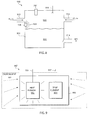
- FIG. 1 illustrates a schematic drawing of a simplified redox flow cell battery system 100 .
- redox flow cell system includes redox flow cell 100 , which includes two half-cells 108 and 110 separated by a membrane 106 .
- An electrolyte 124 is flowed through half-cell 108 and an electrolyte 126 is flowed through half-cell 110 .
- Half-cells 108 and 110 include electrodes 102 and 104 , respectively, in contact with electrolytes 124 and 126 , respectively, such that redox reactions occur at the surface of the electrodes 102 or 104 .
- multiple redox flow cells 100 can be electrically coupled (e.g., stacked) either in series to achieve higher voltage or in parallel in order to achieve higher current. As shown in FIG. 1 , electrodes 102 and 104 are coupled across load/source 120 , through which electrolytes 124 and 126 are either charged or discharged.
- half-cell 110 of redox flow cell 100 When filled with electrolyte, half-cell 110 of redox flow cell 100 contains anolyte 126 and the other half-cell 108 contains catholyte 124 , the anolyte and catholyte being collectively referred to as electrolytes.
- Reactant electrolytes may be stored in separate reservoirs and dispensed into half-cells 108 and 110 via conduits coupled to cell inlet/outlet (I/O) ports 112 , 114 and 116 , 118 respectively.
- I/O inlet/outlet
- an external pumping system is used to transport the electrolytes to and from the redox flow cell.
- Electrolyte 124 flows into half-cell 108 through inlet port 112 and out through outlet port 114
- electrolyte 126 flows into half-cell 110 through inlet port 116 and out of half-cell 110 through outlet port 118 .
- At least one electrode 102 and 104 in each half-cell 108 and 110 provides a surface on which the redox reaction takes place and from which charge is transferred. Suitable materials for preparing electrodes 102 and 104 generally include those known to persons of ordinary skill in the art.
- Redox flow cell 100 operates by changing the oxidation state of its constituents during charging or discharging.
- the two half-cells 108 and 110 are connected in series by the conductive electrolytes, one for anodic reaction and the other for cathodic reaction.
- electrolytes 126 and 124 are flowed through half-cells 108 and 110 through I/O ports 112 , 114 and 116 , 118 respectively as the redox reaction takes place.
- membrane 106 Positive ions or negative ions pass through permeable membrane 106 , which separates the two half-cells 108 and 110 , as the redox flow cell 100 charges or discharges. Reactant electrolytes are flowed through half-cells 108 and 110 , as necessary, in a controlled manner to supply electrical power or be charged by load/source 120 .
- Suitable membrane materials for membrane 106 include, but are not limited to, materials that absorb moisture and expand when placed in an aqueous environment.
- membrane 106 may comprise sheets of woven or non-woven plastic with active ion exchange materials such as resins or functionalities embedded either in a heterogeneous (such as co-extrusion) or homogeneous (such as radiation grafting) way.
- membrane 106 may be a porous membrane having high voltaic efficiency Ev and high coulombic efficiency and may be designed to limit mass transfer through the membrane to a minimum while still facilitating ionic transfer.
- membrane 106 may be made from a polyolefin material and may have a specified thickness and pore diameter.
- a manufacturer having the capability to manufacture these membranes, and other membranes consistent with embodiments disclosed, is Daramic Microporous Products, L.P., N. Community House Rd., Suite 35, Charlotte, N.C. 28277.
- membrane 106 may be a nonselective microporous plastic separator also manufactured by Daramic Microporous Products L.P.
- a flow cell formed from such a membrane is disclosed in U.S. Published Patent App. No. 2010/0003586, filed on Jul. 1, 2008, which is incorporated herein by reference.
- redox flow cell 100 may stacked to form a redox flow cell battery system 150 .
- Stacked redox flow cell battery 150 includes one or more redox flow cells 100 , cells 100 - 1 through 100 -N are shown. Each of cells 100 - 1 through 100 -N includes two half-cells, exemplified by half-cells 203 , 205 , 207 , and 209 in FIG. 1B . End half-cells 203 and 209 may be coupled across load/source 120 . If battery 150 includes a single cell, half cell 203 corresponds with half-cell 108 and half cell 209 corresponds with half cell 110 .
- FIG. 1B shows that there may be any even number of half cells, and thus any number of cells 100 , in battery 150 .
- each of half cells 203 , 205 , 207 , and 209 is formed between pairs of elements 211 , 213 , 215 , 217 , and 219 .
- half cell 203 is formed by elements 211 and 213 ;
- half cell 205 is formed by elements 213 and 215 ;
- half cell 207 is formed by elements 215 and 217 ;
- half cell 209 is formed by elements 219 and 221 .
- element 219 and element 217 are the same element.
- cells 205 and 207 would be absent and element 219 and 213 would be the same.
- Elements 211 and 221 form end plates and each include electrodes.
- element 213 includes a membrane
- element 215 includes an electrode
- element 217 includes a membrane
- element 219 includes a membrane.
- Construction of a flow cell stack is described in U.S. patent application Ser. No. 12/577,134, entitled “Common Module Stack Component Design” filed on Oct. 9, 2009, which is incorporated herein by reference.
- electrolytes sourced from external reservoirs can be flowed through separate half cells.
- catholyte from catholyte reservoir 266 flows through half cells 203 and 207 while anolyte from anolyte reservoir 252 flows through half cells 205 and 209 .
- Elements 211 , 213 , 215 , 217 , 219 , and 221 therefore, each include either a membrane or an electrode and controls the flow of the appropriate electrolyte into half cells 203 , 205 , 207 , and 209 .
- elements 211 and 221 of end half-cells 203 and 209 each include a pre-molded frame and an end-plate assembly that includes an electrode.
- elements 211 and 221 can be structurally similar, but oriented opposite of each other, as is further discussed below.
- elements 213 , 215 , 217 , and 219 all include frames that are structurally identical, with either a membrane or an electrode attached to the frame.
- electrolyte 124 includes an aqueous acid solution.
- the acidic solution includes aqueous hydrochloric acid.
- Electrolyte 124 further includes at least one metal salt (e.g., a metal chloride salt).
- electrolyte 126 comprises an aqueous acid solution.
- the acidic solution includes aqueous hydrochloric acid.
- Electrolyte 126 further includes at least one metal salt (e.g., a metal chloride salt).
- a redox flow cell battery system is based on a Cr/Fe redox pair.
- the remainder of the description will be based on a Cr/Fe redox flow cell battery, however, it should be understood that the concepts described herein may also be applied to other metals.
- both electrolytes 124 and 126 include a solution of FeCl 2 and CrCl 3 in aqueous HCl.
- the redox pairs of the a Cr/Fe redox flow cell battery include Cr 3+ /Cr 2+ and Fe 3+ /Fe 2+ , respectively. Electrical energy is converted during charging into chemical energy through electrochemical reactions. The process is reversed on discharging. Those processes are reflected by the following:
- electrolytes 124 and 126 may undergo the following reactions:
- catholyte 124 includes an aqueous solution of hydrochloric acid and FeCl 2
- anolyte 126 comprises an aqueous solution of hydrochloric acid and CrCl 3
- catholyte 124 may also include CrCl 3 and anolyte 126 may include FeCl 2 so that electrolyte 126 and electrolyte 124 , upon being fully discharged, are the same electrolytic solutions.
- Applying the external power to charge the redox flow cell affects an electron transfer, while a Cl ⁇ ion crosses membrane 106 from anodic half-cell 110 to cathodic half cell 108 and/or H+ ions cross the membrane 106 from cathodic half-cell 108 to anodic half-cell 110 .
- the fully charged redox flow cell is composed of a 100% FeCl 3 solution in cathodic half-cell 108 and 100% CrCl 2 in half-cell 110 on the anode side.
- a fully discharged redox flow cell is, therefore, composed of a 100% FeCl 2 solution in catholyte 124 , and a 100% active CrCl 3 solution in anolyte 126 .
- Fe 3+ is converted to Fe 2+ by addition of an electron from Cr 2+ .
- the conversion of Fe 3+ to Fe 2+ is therefore limited by the availability of Cr 2+ for conversion. Since only 98% of the Cr 3+ initially present is converted to Cr 2+ during charging, less than the full amount of Fe 3+ is converted to Fe 2+ during the discharge cycle. This reduction of charge capacity is carried on with each subsequent cycle, gradually reducing the charge capacity of the redox flow cell.
- a rebalance system as described herein can be utilized to substantially restore the parity between the active iron components in catholyte 124 and the active chromium components in anolyte 126 .
- the restoration of parity between iron and chromium ions may be accomplished by placing the redox flow cell in fluid communication with a rebalance system including at least one electrochemical cell and at least one photochemical cell.
- the restoration of the charge ratio and acidic concentration of the electrolyte compositions may be effected, for example, through the reduction of Fe 3+ ions, since a further reduction of Cr 3+ ions will result in a lower current yield.
- the electrochemical reduction of Fe 3+ results in the formation of Cl 2 gas.
- H 2 and Cl 2 gases can potentially yield volumes of H 2 and Cl 2 gases.
- the H 2 and Cl 2 gases may be removed to a separate reaction chamber for processing.
- the rebalance systems described herein will effect the removal of the H 2 and Cl 2 gases from the system and will recombine H 2 and Cl 2 to replenish the supply of HCl in the electrolytes, all while rebalancing the active ion ratios of anolyte 126 and catholyte 124 .
- FIG. 2 illustrates a redox flow cell battery system 200 .
- Redox flow cell battery system 200 includes redox flow cell 100 , an electrochemical rebalance cell 238 , and a photochemical cell 214 .
- Redox cell battery 100 is shown with cathode compartment 108 and anode compartment 110 , which are separated by membrane 106 , as illustrated in FIG. 1A , but may include any number of individual cells as illustrated in FIG. 1B .
- Electrochemical rebalance cell 238 and photochemical cell 214 form the rebalance system.
- H 2 produced in anode compartment 110 may be transferred from redox cell 100 through conduit 248 and into anolyte reservoir 252 , which also contains anolyte 126 .
- H 2 may be vented from outlet 210 to photochemical cell 214 of the rebalance system. Vented H 2 may be carried along conduit 212 and into photochemical cell 214 via inlet 216 .
- Electrochemical cell 238 includes anode compartment 244 and cathode compartment 240 . Disposed therein are anode 294 and cathode 292 . Suitable anode and cathode materials are further described below with respect to FIG. 3 .
- Electrochemical rebalance cell 238 allows the reduction of Fe 3+ to Fe 2+ to be performed to restore the charge balance. Applying power to the electrodes of electrochemical rebalance cell 238 affects the reduction of Fe 3+ to Fe 2+ to restore the system charge balance.
- the reduction of Fe 3+ ions can take place in different ways. For example, the reduction of Fe 3+ ions may take place at cathode 292 of electrochemical rebalance cell 238 through the electrochemical generation of Cl 2 at anode 294 :
- Photochemical cell 214 houses ultraviolet source 218 .
- Ultraviolet source 218 may be encapsulated by a shell to protect it from exposure to substances (e.g., Cl 2 and H 2 ) within photochemical cell 214 .
- the shell may be composed of quartz, glass, or a polymeric material capable of transmitting ultraviolet light at wavelengths sufficient to promote the reaction of H 2 and Cl 2 to form HCl.
- ultraviolet source 218 may placed outside of photochemical cell 214 , wherein ultraviolet source 218 is separated from the inside of photochemical cell 214 by a window.
- the window is composed of quartz.
- photochemical source 218 produces ultraviolet radiation 220 , which may be used to effectively convert H 2 and Cl 2 present in photochemical cell 214 into HCl in the following manner:
- the HCl product formed in photochemical cell 214 may then be drained through outlet 224 .
- Some embodiments may include a valve 226 that can be used to drain HCl out of rebalance system 200 via conduit 228 .
- the HCl product of photochemical cell 214 may be directed through conduit 230 and into anode compartment 240 of electrochemical cell 238 via inlet 236 .
- An advantage of the use of a photochemical cell is the ability of the system to retain the Cl 2 lost during rebalancing of the charge ratio. If the Cl 2 was simply vented, the acidity of the electrolyte solutions would become reduced, which would alter the charge capacity and operating characteristics of the flow cell battery system.
- Use of a photochemical cell to regenerate HCl allows the acidity to be maintained by reintroducing acid that would have been lost during a rebalancing procedure.
- suitable sources of ultraviolet radiation may include sources that emit light having a wavelength from about 100 nm to about 450 nm. In some embodiments, ultraviolet radiation source 218 will emit light having a wavelength of about 370 nm to about 430 nm. In some embodiments, ultraviolet radiation source 218 emits light having a wavelength of about 390 nm to about 410 nm.
- the temperature and pressure resulting from the operation of ultraviolet source 218 may be closely monitored by sensors 246 .
- Sensors 246 may, for example, include temperature sensors of any type, such as thermocouples, thermistors, or any other device for measuring temperature. Sensors 246 may also include pressure sensors. In some embodiments, it may be desirable to keep the temperature below 200° C. during the conversion of Cl 2 and H 2 . If a high temperature condition exists, battery system 200 may take action to lower the temperature.
- HCl introduced into electrochemical cell 238 will dissociate into H + and Cl ⁇ in aqueous anolyte contained in anode compartment 240 .
- Selectively-permeable membrane 242 may allow the transport of H + from anode compartment 240 into cathode compartment 244 . Suitable materials for membrane 242 include those described below with respect to FIG. 3 .
- the flow of H + into cathode compartment 244 will raise the catholyte level and decrease the concentration of the components of the catholyte. Catholyte levels and concentrations may be equilibrated by catholyte reservoir 266 . Diluted catholyte may be drained from cathode compartment 244 through outlet 260 .
- the diluted catholyte is transported along conduit 262 and into catholyte reservoir 266 via inlet 264 . There, the diluted catholyte may be equilibrated and again dispelled via outlet 278 . The equilibrated catholyte is then transported through conduit 280 and reintroduced into cathode compartment 244 via inlet 282 .
- Catholyte in cathode compartment 108 of redox cell 100 may be drained through outlet 112 and replenished in catholyte reservoir 266 via conduit 274 and inlet 276 .
- Replenished catholyte 124 exits catholyte reservoir 266 though outlet 267 , which is then transported through conduit 268 and reintroduced into cathode compartment 108 via inlet 114 .
- anolyte reservoir 252 feeds fresh anolyte from outlet 250 into anode compartment 110 via conduit 248 and inlet 118 .
- the anolyte may be drained from anode compartment 110 through outlet 116 and transported along conduit 256 for reintroduction into anolyte reservoir 252 via inlet 254 .
- the rebalance system may include a single rebalance cell where photochemical cell 214 is combined with anode compartment 240 of electrochemical rebalance cell 238 , as described with respect to FIGS. 3 and 4 below.
- the electrochemical rebalance cell may reflect the combination of an electrochemical cell and a photochemical cell, by incorporating at least one source of ultraviolet radiation in the electrochemical rebalance cell.
- FIG. 3 illustrates a combined rebalance cell where the anode compartment of an electrochemical rebalance cell also serves as the photochemical cell of the combined rebalance cell.
- Combined rebalance cell 300 includes cathode compartment 244 and anode compartment 240 , which are separated by porous membrane 242 .
- porous membrane 242 comprises porous layer 313 and ion-selective layer 315 .
- membrane 242 may be selectively permeable for certain species.
- Membrane 242 may be selected specifically to resist substantial degradation by aqueous Cl 2 .
- membrane 242 may comprise a polymeric base.
- Exemplary polymeric bases may include, but are not limited to, bases comprising polyethylene.
- ion-selective layer 315 may comprise a polyfluorinated layer or a perfluorinated layer. In certain embodiments, ion-selective layer 315 may be selectively permeable to certain ionic species, such as H + .
- Exemplary layers may include, but are not limited to, perfluorinated materials. In some embodiments, the perfluorinated materials may include one or more units having the following structure:
- ion-selective layer 315 may comprise a sulfonated tetrafluoroethylene based fluoropolymer-copolymer such as Nafion®, manufactured by E. I. duPont de Nemours and Company of Wilmington, Del.
- ionselective layer 315 may be further reinforced by a chemically-resistant material such as Teflon®.
- Anode compartment 240 contains anode 294
- cathode compartment 244 contains cathode 292
- anode 294 may include a mixed metal oxide layer 309 disposed on metal substrate layer 311 .
- anode 294 may include a mixed metal oxide without substrate layer 311 .
- Anode 294 may be selected to resist substantial degradation from exposure to aqueous Cl 2 .
- anode 294 comprises a carbon or mixed-metal oxide disposed on a substrate.
- the mixed metal oxide comprises ruthenium and titanium oxide.
- the mixed metal oxide comprises iridium and ruthenium oxide.
- the substrate is selected from titanium and titanium oxide.
- the carbon or mixed-metal oxide may be disposed on the substrate in such a manner that allows at least some of the substrate to remain exposed after deposition of the carbon or metal oxide. In some embodiments, the carbon or mixed metal oxide and the substrate will form two separate and distinct layers.
- Anode compartment 240 further holds electrolyte 319 , the volume of which is indicated by electrolyte level 308 .
- Space 314 defines the area between electrolyte level 308 and the top of anode compartment 240 .
- electrolyte 319 includes aqueous HCl
- powering cell 300 will effect the formation of Cl 2 at anode 294 , which then collects in space 314 .
- H 2 from an external source e.g., anolyte reservoir 252 , FIG. 2
- Anode compartment 240 further contains ultraviolet source 218 , which may be used to expose space 314 to ultraviolet radiation 220 .
- Ultraviolet source 218 may be encapsulated by a shell to protect it from exposure to substances (e.g., Cl 2 and H 2 ) within space 314 .
- the shell may be composed of quartz, glass, or a polymeric material capable of transmitting ultraviolet light at wavelengths sufficient to promote the reaction of H 2 and Cl 2 to form HCl.
- ultraviolet source 218 may placed outside of anode compartment 240 , wherein ultraviolet source 218 is separated from space 314 by a window.
- the window is composed of quartz, quartz, glass, or a polymeric material capable of transmitting ultraviolet light at wavelengths sufficient to promote the reaction of H 2 and Cl 2 to form HCl.
- the exposure of H 2 and Cl 2 to ultraviolet radiation 220 effects the formation of HCl, which then dissociates in aqueous anolyte 319 as HCl.
- the heat and pressure resulting from the operation of ultraviolet source 218 may be closely monitored by sensors 246 .
- the anode compartment further includes a Cl 2 /H 2 sensor 247 disposed therein to monitor the concentrations of Cl 2 and H 2 present in the rebalance cell.
- a Cl 2 /H 2 sensor 247 may be disposed in photochemical cell 214 to monitor the concentrations of Cl 2 and H 2 present in the rebalance cell. Ideally, to safely control the reaction that occurs in photochemical cell 214 , a chlorine rich environment is desired. In some embodiments, a chlorine/hydrogen concentration ratio may approach 2:1. However, an excessive amount of chlorine is also undesirable and therefore some embodiments may limit the amount of chlorine in the gas mixture. Sensor 247 can be utilized to monitor the concentration ratio of chlorine to hydrogen.
- FIG. 8 illustrates an exemplary system 900 that includes a gas monitoring system to measure the relative concentrations of a gaseous mixture.
- System 900 may be a portion of a combination rebalance cell or a photochemical cell that is used to produce HCl from a mixture of H 2 and Cl 2 .
- system 900 includes a compartment 902 coupled to receive various substances into a space 920 from inlets 920 and 912 .
- compartment 902 may receive H 2 gas via inlet 910 and Cl 2 gas via inlet 912 .
- Compartment 902 may also include an ultraviolet source 906 , which may be used to expose space 920 to ultraviolet radiation 908 .
- the exposure of H 2 and Cl 2 to ultraviolet radiation 908 may effect the formation of hydrochloric acid (HCl) which may then be dissolved in an aqueous solution 904 .
- Solution 904 may include pure water (H 2 O), aqueous acidic solutions, or any other solution that will at least partially dissolve HCl.
- the heat and pressure resulting from the operation of ultraviolet source 906 may be closely monitored by a sensor 916 .
- sensor 916 may be coupled to various control and feedback systems such that temperature and pressure of compartment 902 may be maintained within a predefined operating range.
- compartment 902 may also include an outlet 914 that is coupled to an external system to remove the aqueous HCl solution generated in compartment 902 .
- compartment 902 may include a sensor 947 that monitors the concentrations Cl 2 and H 2 and/or ratio of the ratio Cl 2 :H 2 present in system 900 .
- FIG. 9 illustrates a block diagram of exemplary sensor 947 that may measure the ratio of H 2 :Cl 2 (or Cl 2 :H 2 ) in a given environment 901 .
- sensor 947 may, in turn, be used in any setting involving the combination of H 2 and Cl 2 such as, in the generation of HCl from chloro-alkali plants, neutralization of Cl 2 , or other such settings requiring a controlled H 2 —Cl 2 reaction.
- the use of sensor 947 is not limited to that of a H 2 and Cl 2 environment, but may be used to measure a concentration or ratio of any (and any number) of gasses in a gaseous mixture.
- sensor 947 may include a heat element 952 and a temperature sensing element 954 .
- Heat element 952 may include any heat source such as a resistive heating source, or any such element capable of generating net heat (power).
- Temperature sensing element 954 may include any temperature sensing element, including thermocouples, thermisters, IC sensors, IR sensors, or any other device capable of measuring a temperature close to heat element 952 .
- heat element 952 and temperature sensing element 954 may be further encapsulated in an enclosure 956 .
- Enclosure 956 may be formed, for example, from glass, plastic, metal, or any other type of material.
- heat element 952 may be coupled to generate net power (heat) by receiving a signal via line 905 (current or voltage signal), and temperature sensing element 954 may provide a temperature signal, which results from heating from heat element 952 , via line 907 .
- heat generated by heat element 952 may be transferred to environment 901 and enclosure 956 .
- the rate at which heat is transferred between heat element 952 and environment 901 may depend on the thermal resistivity of environment 901 and the thermal resistivity of enclosure 956 .
- the thermal resistivity of enclosure 956 may depend on the type and physical characteristics of the material(s) used to create enclosure 956 .
- materials that form enclosure 956 may be chosen such that their thermal resistivity is small (negligible) when compared with the environmental thermal resistivity.
- the thermal conductivity of H 2 is much greater than the thermal conductivity of Cl 2 (by approximately a factor of 15).
- a change in the concentration ratio H 2 :Cl 2 in a H 2 , Cl 2 mixture may cause a significant change in the thermal resistivity of environment 901 .
- the thermal resistivity of environment 901 may decrease because the thermal conductivity of H 2 is much greater than the thermal conductivity of Cl 2 (as mentioned above).
- the decrease in the thermal resistivity of environment 901 may cause more heat from heat element 952 to be dissipated to environment 901 , thereby cooling heat element 952 .
- the concentration of Cl 2 in environment 901 increases, the thermal resistivity of environment 901 may increase which, in turn, may cause less heat from heat element 952 to be dissipated to environment 901 .
- a concentration ratio of H 2 :Cl 2 may be estimated.
- FIG. 10 further depicts an equivalent thermal circuit diagram illustrating the operation of sensor 947 .
- Enclosure thermal resistivity and environment thermal resistivity are depicted as (equivalent) resistors ⁇ ′ and ⁇ , respectively.
- heat element 952 may generate a net power P by receiving (via line 905 ) a signal, such as a constant current, constant voltage, or any other signal capable of generating a net power across heat element 952 .
- heat element 952 may generate net heat P by receiving, from a known voltage source V, a current I via line 905 .
- temperature sensing element 954 may provide (via line 907 ) a temperature reading T associated with heat element 952 .
- temperature reading T may include any value that corresponds directly or indirectly to a given temperature sensed by temperature sensing element 954 .
- temperature reading T may include a value that may indicate the temperature sensed by temperature sensing element 954 or a value that may indicate the temperature sensed by temperature sensing element 954 relative to an ambient temperature.
- temperature sensing element 954 may indicate an ambient temperature reading T a associated with environment 901 .
- heat P generated by heat element 952 may be transferred to environment 901 and may raise the temperature at temperature sensing element 954 (temperature reading T).
- the temperature read by temperature sensing element 954 depends on the heat (power) P generated across heat element 952 and the heat transferred to environment 901 .
- the rate at which heat P is transferred through environment 901 depends on the enclosure thermal resistivity ⁇ ′ and environmental thermal resistivity ⁇ . As discussed above ⁇ ′ may be negligible when compared with ⁇ , therefore;
- environmental thermal resistivity ⁇ also depends on a ratio x of the concentrations of the H 2 and Cl 2 mixture. Therefore,
- ratio x of the H 2 , Cl 2 concentration may be computed from temperature reading T received from temperature sensing element 954 .
- the relationship between ⁇ and x is derived from one or more plots typically developed from laboratory measurements under controlled conditions.
- corresponding values of ⁇ and x derived from the plots mentioned above may be stored in a memory (not shown) that may be included as part of control and feedback circuitry 970 .
- sensor 947 may be coupled to the control and feedback system 970 (via lines 905 and 907 ) and may be configured to calculate x based on temperature reading T and accordingly adjust the proportion (concentration) of H 2 , Cl 2 in the mixture such that a controlled reaction may be maintained.
- FIG. 6 is an exemplary plot depicting the relation between environmental thermal conductivity (1/ ⁇ ) and ratio x.
- the plot depicts Cl 2 :H 2 relative concentration ratio x on the x-axis and environmental thermal conductivity (1/ ⁇ ) on the y-axis.
- a corresponding value of ratio x may be obtained.
- corresponding values of ⁇ and x derived from the plot depicted in FIG. 6 and may be stored in a memory included as part of relevant control and feedback circuitry 970 .
- FIG. 11 illustrates an alternate sensor 947 .
- temperature sensing element 954 is a thermocouple 972 .
- Thermocouple 972 may be configured to provide a voltage reading V′ (across line 907 ) in response to a temperature T sensed by temperature sensing element 954 .
- a net power P may be generated across heat element 952 .
- the temperature sensed by thermocouple 972 may change which in turn may cause voltage reading V′ to appear across line 907 .
- the relationship between V′ and temperature T sensed by thermocouple 72 is derived from one or more plots typically developed from laboratory measurements under controlled conditions, as depicted in FIG. 6 .
- corresponding values of T and V′ derived from the plots may be stored in a memory (not shown) that may be included as part of control and feedback circuitry 370 .
- ratio x may be computed in a manner similar to that discussed with respect to equation 2, and control and feedback system 970 may accordingly adjust the proportion (concentration) of the H 2 , Cl 2 in the mixture such that a controlled reaction may be maintained.
- FIG. 12 illustrates a sensor 947 that is formed using a thermistor.
- sensor 957 may include a thermistor 982 having a resistance R that varies as a function of a temperature T sensed by the environment surrounding the thermistor.
- Thermistor 982 includes both a heat element and temperature sensing element as shown in previous embodiments.
- a net power P may be generated across thermistor 982 . For example, if net power P is generated across thermistor 982 from known voltage source V and current I, then:
- R o is the resistance of thermistor 982 at a reference temperature T 0 and B is a device constant.
- R 0 , T 0 , and B are included as part of the manufacturer's specifications associated with thermistor 982 .
- resistance R of thermistor 982 corresponds to temperature T a of environment 901 .
- P t the heat transferred between thermistor 982 and the surrounding environment
- R inf R 0 e ⁇ B/T 0
- V function( K, T a ) (9)
- K is the heat transfer coefficient between thermistor 982 and environment 901 , K is directly related to environmental thermal resistivity 8 (as discussed with respect to FIG. 10 ) which further depends on ratio x. Therefore, from equation 9:
- V function( x, T a ) (10)
- H 2 and Cl 2 ratio x is derived from known voltage source V and temperature T a .
- corresponding values of T a and V derived from equation 4 discussed above may be stored in a memory (not shown) that, for example, is included as part of control and feedback circuitry 970 .
- control and feedback system 970 may use the computed value of x, which may be utilized to adjust the proportion (concentration) of the H 2 Cl 2 mixture such that a controlled reaction may be maintained.
- sensor 947 may be used to monitor a relative concentration of a gaseous mixture that may be present in a static environment such as environment 901 that may be present in compartment 992 .
- environment 901 it may be possible for environment 901 to be a dynamic environment wherein one or more gases (such as a H 2 and/or Cl 2 ) are moving at a constant and/or variable rate.
- FIG. 13 illustrates an embodiment of sensor 947 that may be used to monitor relative concentrations of a gaseous mixture in a dynamic environment 991 . As shown in FIG.
- sensor 947 may further include a porous membrane 992 that at least partially encapsulates enclosure 956 such that a space 994 exists between membrane 992 and enclosure 956 .
- membrane 992 may include a plastic membrane, or any other type of membrane that will allow gases from environment 991 to flow through it without affecting the relative concentrations of the gases.
- the environment encapsulated by membrane 992 in space 993 ) may be similar if not identical to static environment 901 discussed with respect to FIG. 10 . Therefore, in a manner similar to that discussed with respect to FIG. 10 , a ratio x of the relative concentration of gases (such as Cl 2 :H 2 ) in dynamic environment 991 may be calculated.
- the resulting increase in H + in anolyte 319 may be controlled by permeable membrane 242 .
- Ion-selective layer 315 may affect the passage of H + into cathode compartment 244 and aqueous catholyte 317 .
- This passage typically results in a drop of anolyte level 308 because of transmission of water along with the hydrogen ions.
- about 4 to about 6 molecules of H 2 O may pass with each H + molecule that traverses membrane 242 into the cathode compartment 244 .
- This passage results in a drop in electrolyte level 308 , thereby concentrating the components of electrolyte 319 .
- the passage of H 2 O into cathode compartment 244 will cause a decrease in the concentration of the components dissolved in electrolyte 317 .
- upper sensor 332 and lower sensor 334 are disposed in anode compartment 240 to detect and control electrolyte level 308 .
- electrolyte level 308 reaches lower sensor 334
- anode compartment 240 is drained through outlet 340 , as controlled by valve 342 .
- Electrolyte is then re-introduced into anode compartment 240 via conduit 244 through inlet 310 until electrolyte level 308 reaches upper sensor 332 .
- a valve 346 may control the introduction of electrolyte into anode compartment 240 through conduit 312 .
- valve 312 may remain open for some period of time after electrolyte begins to fill anode compartment 240 in order to flush compartment 240 . Once anode compartment 240 is refilled, power is once again applied to electrodes 294 and 292 to saturate electrolyte 319 and begin production of chlorine gas.
- Electrolyte 317 may be flowed through cathode compartment 244 so that cathode compartment 244 is always full.
- electrolyte 319 and electrolyte 317 come from the same storage tank.
- electrolyte 319 may be sourced from a separate tank.
- FIG. 4 illustrates a redox flow cell battery system 400 that includes redox flow cell 100 coupled to rebalancing cell 300 .
- redox flow cell 100 is illustrated with a single cell that includes cathode compartment 108 and anode compartment 110 separated by membrane 106 .
- H 2 produced in anode compartment 110 may be transferred from redox cell 100 through conduit 248 and into anolyte reservoir 252 through inlet 250 , which also contains anolyte 126 . From there, H 2 may be vented from outlet 210 and carried along conduit 212 and into anode compartment 240 of rebalance cell 300 via inlet 336 .
- Rebalance cell 300 also houses cathode compartment 244 .
- Anode compartment 240 and cathode compartment 244 are separated by porous membrane 242 .
- Cathode compartment 244 contains cathode 292 , while anode compartment 240 contains anode 294 .
- anolyte in anode compartment 240 comprises aqueous HCl
- the process of oxidation will effect the formation of Cl 2 at anode 294 , which then collects at the top of anode compartment 240 .
- H 2 introduced through inlet 336 also collects at the top of anode compartment 240 .
- Anode compartment 240 includes ultraviolet source 218 , which may be used to expose the H 2 and Cl 2 to ultraviolet radiation 220 .
- Ultraviolet source 218 may be encapsulated by a shell to protect it from exposure to substances (e.g., Cl 2 and H 2 ) within anode compartment 240 .
- H 2 and Cl 2 effects the formation of HCl, which then dissociates in the aqueous catholyte as H + and Cl ⁇ .
- the heat and pressure resulting from the operation of ultraviolet source 218 may be closely monitored by sensors 246 .
- H 2 and Cl 2 concentrations may be monitored through gas sensor 247 .
- Permeable membrane 242 may allow for the passage of H + into cathode compartment 244 and the aqueous catholyte contained therein. This passage typically results in a drop in the electrolyte volume in anode compartment 240 .
- the level of electrolyte in anode compartment 240 is controlled to be between lower sensor 334 and upper sensor 332 .
- a drop in electrolyte level detected by lower sensor 334 will stop the flow of power and effect the draining of electrolyte through outlet 340 and valve 342 . From there, the electrolyte may be transported along conduit 344 and into catholyte reservoir 266 via inlet 346 .
- Electrolyte may then be flowed from outlet 348 and along conduit 312 to refill anode compartment 240 via inlet 310 .
- valve 342 may remain open for some period of time after electrolyte begins to fill anode compartment 240 in order to flush compartment 240 . Once anode compartment 240 is refilled, power is once again applied to electrodes 294 and 292 to begin production of chlorine gas.
- the refilling of anode compartment 240 may be accomplished by a second arm off of conduit 274 .
- battery system 400 may lack conduit 312 .
- a second arm off of conduit 274 (not shown) may be implemented to effect the transfer of electrolyte to anode compartment 240 via inlet 310 for refilling.
- valve(s) may be implemented to control the fill.
- catholyte from cathode compartment 244 may be placed in fluid communication with catholyte reservoir 266 by other means.
- redox battery system 400 may lack conduit 262 .
- a second arm off of conduit 274 may be implemented to affect the transfer of electrolyte from cathode compartment 244 to catholyte reservoir 266 .
- valve(s) may be implemented to control the transfer.
- Catholyte in cathode compartment 108 of redox flow cell 100 may be drained through outlet 112 and replenished in catholyte reservoir 266 via conduit 274 and inlet 276 .
- Replenished catholyte 124 exits catholyte reservoir 266 though outlet 267 , which is then transported through conduit 268 and reintroduced into cathode compartment 108 via inlet 114 .
- anolyte reservoir 252 feeds fresh anolyte 126 from outlet 250 into anode compartment 110 via conduit 248 and inlet 118 .
- the anolyte may be drained from anode compartment 110 through outlet 116 and transported along conduit 256 for reintroduction into anolyte reservoir 252 via inlet 254 .
- inlet 346 may be placed at the top of catholyte reservoir 266 , instead of the side as depicted in FIG. 4 .
- Other rearrangements to I/O port and conduit placements depicted in FIG. 4 are obvious and have the ability to effect similar results.
- FIG. 5 illustrates a control system 500 for controlling rebalance cell 300 .
- An example of a control system is described in U.S. Patent Application entitled “Control System for a Flow Cell Battery”, filed concurrently herewith, which claims priority to U.S. Provisional Patent Application No. 61/182,660 entitled “Control System for a Flow Cell Battery”, filed May 28, 2009, both of which are incorporated herein by reference.
- control system 500 includes a controller 510 .
- Controller 510 includes one or more processors, volatile and non-volatile memory to store data and programming, input signal processing that may include analog-to-digital converters to receive and digitize data, and output signal processing that may include digital-to-analog converters to provide variable signals as needed.
- controller 510 may receive signals related to temperature and pressure from sensors 246 , signals related to the concentration of hydrogen to chlorine gas from sensor 247 , a lower level sensor signal from lower sensor 334 , and an upper level signal from upper sensor 332 . From these input signals, controller 510 provides one or more signals to control the current between electrodes 292 and 294 , provide alarms if an overpressure or over temperature situation develops, and controls the refill process to restore electrolyte levels in anode compartment 240 .
- controller 510 may be coupled to a communication bus, through which the status of rebalance cell 228 may be reported and comments such as, for example, a rebalance on command signal, can be received from the control system that controls a redox battery system.
- a redox flow cell battery system includes a main processor, for controlling the operation of the redox flow cell and a rebalance cell processor for controlling the operation of the rebalance cell.
- Rebalance cell processor and main processor operate independently. In some embodiments, however, the main processor and the rebalance cell processor transfer state information. For example, if the rebalance cell is going into a shutdown state, the main controller is informed of this transition through communication with the rebalance cell processor. Under such circumstances the main processor will continue to operate the redox flow cell battery system until it deems it necessary to shut the redox flow cell battery system down. If, however, the main processor shuts down the redox flow cell battery system, the shutdown signal is sent from the main processor to the rebalance cell processor requesting a shutdown of the rebalance cell until the main processor restarts the rebalance cell system.
- the production of chlorine can be governed by the ratio of hydrogen concentration to chlorine concentration present in anode compartment 240 .
- the ratio of chlorine to hydrogen is kept between about 1 or about 2.
- FIG. 6 illustrates the power applied to electrodes 294 and 292 as a function of the ratio of chlorine concentration to hydrogen concentration.
- the function is parabolic.
- FIG. 7 illustrates an example of a state machine function 800 that may be executed by controller 510 illustrated in FIG. 5 .
- State machine function 800 may be one embodiment of a processor-accessible storage medium configured to store instructions to be executed by a processor.
- a processor-accessible storage medium may include any storage media accessible by a processor during use to provide instructions and/or data to the processor.
- a processor accessible storage medium may include storage media such as magnetic or optical media, e.g., disk (fixed or removable), tape, CD-ROM, or DVD-ROM, CD-R, CD-RW, DVD-R, DVD-RW, or Blu-Ray.
- Storage media may further include volatile or non-volatile memory media such as RAM (e.g.
- SDRAM synchronous dynamic RAM
- DDR double data rate SDRAM
- LPDDR2 low-power DDR SDRAM
- RDRAM Rambus DRAM
- SRAM static RAM
- ROM Flash memory
- non-volatile memory e.g. Flash memory
- USB Universal Serial Bus
- Storage media may include storage media accessible via a communication medium such as a network and/or a wireless link.
- Controller 510 may begin in initialization state. From initialization state the controller cycles through fill and drain states to prepare for performing rebalance reactions. If the rebalance cell has fluids in the static side of the cell (e.g., the anode compartment), the controller transitions the rebalance system to the INITDrain state. In the INTDrain state, substantially all of the fluid in the rebalance system is drained from the static side. After the rebalance cell is drained, the rebalance system transitions to INITFill state. In INITFill state the compartments of the rebalance cell are filled with the iron side electrolytes. If the rebalance system does not have fluids in the compartments, the first INITDrain state may be skipped and the system may go directly to the INITFill state.
- the rebalance system controller cycles through the INITDrain and INITFill cycles at least three times. The number of cycles taken are monitored when each INITFill stage has ended using the RBCENV state.
- controller 510 transitions to initial fill state INITFill.
- INITFill controller closes drain valve 342 and opens fill valve 346 . If, in RBC INI, one or both of switches 334 and 332 are closed, then controller 510 transitions to drain state INITDrain where fill valve 346 is closed and drain valve 342 is opened. After a predetermined time, for example about three minutes, and if switch 334 is open, then controller 510 transitions to initial fill state INITFill.
- INITFill drain valve 342 In initial fill state INITFill drain valve 342 is closed and fill valve 346 is opened until switch 332 closes, after which rebalance controller transitions to delay state RBCENV.
- state RBCENV valves 342 and 346 are both closed and a wait of a predetermined time, for example about five minutes, is initiated. If the chlorine gas level, as measured by sensor 247 , increases above a threshold level, for example, about 5%, then controller transitions back to drain state INITDrain. Otherwise, once the wait period is over, the controller transitions to on state RBC ON. States INITFill and RBC ENV may also transition to a shutdown state ShutDown if a fault condition is detected.
- fault conditions include, for example, an LED current does not ramp upfailure, a high temperature condition, a hardware failure, a failure of gas detection sensor or detection that the gas detection sensor is in contact with fluid, a control voltage failure, a request from the main processor, a timeout condition, a failure of switches, or some other fault.
- a signal received from the main controller directing that rebalance cell be shut down can also be interpreted as a fault resulting in a transition to shutdown state.
- valves 342 and 346 are off and rebalance current is supplied between electrodes 292 and 294 .
- LED may be turned on to provide ultraviolet light to the rebalance cell to initiate the reaction of H 2 and Cl 2 .
- the current supplied between electrodes 292 and 294 which results in Cl 2 production, can be controlled in response to measurements of the ratio of hydrogen to chlorine concentrations as detected by sensor 247 . Further details regarding the reaction of H 2 and Cl 2 is described in U.S. Patent Application entitled “Methods of Producing Hydrochloric Acid from Hydrogen Gas and Chlorine Gas”, filed concurrently herewith, which claims priority to U.S. Provisional Patent Application No. 61/182,335 entitled “Methods of Producing Hydrochloric Acid from Hydrogen Gas and Chlorine Gas”, filed May 28, 2009, both of which are incorporated herein by reference.
- controller can transition rebalance system from on state RBC On to hibernate state Hibernate.
- a threshold value for example about 17.5V, or the actual SOC is less than 12%
- controller can transition rebalance system from on state RBC On to hibernate state Hibernate.
- hibernate state 814 the current between electrodes 292 and 294 is shut off and the photochemical LED is shut off.
- the controller can transition to INITDrain and rebalance cell restarts.
- a drop of the voltage across redox flow cell 100 below the threshold value may indicate substantial discharge of redox flow cell 100 whereas an increase about the restart threshold value indicates the start of a charging cycle for redox flow cell 100 .
- controller 510 transitions to standby mode 816 where current between electrodes 292 and 294 is turned off. Once the temperature decreases below a second temperature threshold, for example 75 C, and the pressure decreases below a second pressure threshold, the controller may transition the rebalance cell back to on RBC On state. If a fault is detected, controller can initiate transition from standby mode RBC StandBy to shutdown state ShutDown.
- a first temperature threshold for example 95 C
- a rate threshold for example 3 C/sec
- controller transitions the system to partial fill state RBC Partial fill when both low level switch 334 and high level switch 332 are open, a partial fill counter is less than a set value (for example six), the state of charge (SoC) is less than a threshold (for example 20%), and flow cell system is in discharge mode.
- a partial fill counter is less than a set value (for example six)
- the state of charge (SoC) is less than a threshold (for example 20%)
- flow cell system is in discharge mode.
- fill valve is opened until both low level switch 334 and high level switch 332 are closed, at which point controller transitions the system back to the RBC On state.
- controller transitions from partial fill state to shutdown.
- the RBC Partial fill state is used to rebalance the fluid level in the cell.
- the fluid level of the static compartment ( 240 ) gradually decreases due to transfer of water between compartments during rebalancing.
- the static compartment 240 is filled with fluid until upper sensor shows that the chamber has been refilled.
- Controller transitions to drain state RBC Drain when switches 332 and 334 are open, the number of partial fills is greater that the set value (for example six), the SoC is less than a threshold (for example 20%), and flow cell system is in discharge mode.
- drain state RBC Drain the rebalance current between electrodes 292 and 294 is shut off and drain valve 342 is opened.
- controller transitions from RBC Drain state to RBC Fill state.
- RBC Fill state 820 drain valve 342 is closed and fill valve 346 is open. Controller transitions back to on RBC_On state when certain controller switches close or a time out has been reached (for example 9 minutes).
- the rebalance current (the current supplied between electrodes 292 and 294 of the rebalance cell) is off and the UV LED light is off
- Controller may continue to monitor sensors 246 , 247 , and level sensors 334 and 332 and may continue to report the status of rebalance cell, as indicated by the sensors, through a communications bus, for example an I2C bus, to a system controller of a flow cell battery. If rebalance cell is turned on and there are no faults, or a fault reset has been received, through the communications bus, controller transitions to rebalance initialization state.
Abstract
Description
- This application claims the benefit of U.S. Provisional Application No. 61/182,099 entitled “Flow Cell Rebalancing” filed on May 28, 2009; and to U.S. Provisional Patent Application No. 61/182,076 entitled “Hydrogen Chloride Level Detector”, filed May 28, 2009.
- 1. Field of the Invention
- The present disclosure relates to reduction-oxidation (redox) flow cells and, in particular, to rebalance systems that may be utilized in redox flow cells.
- 2. Description of the Relevant Art
- There is an increasing demand for novel and innovative electric power storage systems. Redox batteries have become an attractive means for such energy storage. In certain applications, a redox flow battery may include one or more redox flow cells. Each of the redox flow cells may include positive and negative electrodes disposed in separate half-cell compartments. The two half-cells may be separated by a porous or ion-selective membrane, through which ions are transferred during a redox reaction. Electrolytes (anolyte and catholyte) are flowed through the half-cells as the redox reaction occurs, often with an external pumping system. In this manner, the membrane in a flow cell battery operates in an aqueous electrolyte environment. In some applications, an iron-ion containing aqueous hydrochloric acid solution may be used as the catholyte, while a chromium-ion containing aqueous hydrochloric acid solution may be used as the anolyte. In some applications, a mixture of chromium and iron containing solutions may be used on both sides of the redox cell. The use of mixed reactants eliminates the requirement for a highly-selective membrane since the electrolyte composition of both half cells is identical in the discharged state.
- Typically, the charging and discharging of the redox flow battery results in a disparity of states of charge between the two electrolyte solutions. Parasitic reactions competing with the reduction of certain ions may result in formation of unwanted side products. For example, in the case of acidic electrolytes, certain parasitic reactions may generate hydrogen gas.
- Therefore, there exists a need to develop a redox cell system that effectively removes or recycles parasitic side products produced during the charge/discharge cycles of a flow cell battery to rebalance the charge states between the two electrolytic solutions.
- In an embodiment, a redox flow cell battery system includes a redox flow cell and a rebalance system coupled to the redox flow cell. The rebalance system includes at least one electrochemical rebalance cell placed in fluid communication with at least one photochemical cell that includes at least one source of ultraviolet radiation. In some embodiments, the redox flow battery system further includes at least one anolyte reservoir that includes an aqueous anolyte solution. In some embodiments, the anolyte solution includes an acid and at least one metal salt. In some embodiments, the redox flow battery system further includes at least one catholyte reservoir including a catholyte solution.
- Consistent with some of the embodiments described herein, a rebalance cell and methods of using the same are provided. In some embodiments, the rebalance cell includes at least one source of ultraviolet radiation, at least one anolyte solution, at least one catholyte solution, an anode compartment and a cathode compartment separated by a membrane, and an electrode disposed in each of said anode and cathode compartments. In some embodiments, the at least one anolyte solution includes an aqueous acid and at least one metal salt. In some embodiments, the at least one catholyte solution also includes an aqueous acid and at least one metal salt.
- In certain embodiments described herein, a rebalance system including at least one rebalance cell is described. In some embodiments, the rebalance system further includes at least one anolyte reservoir that includes at least one aqueous anolyte solution. In some embodiments, the at least one anolyte solution includes an acid and at least one metal salt. In some embodiments, the rebalance system further includes at least one catholyte reservoir containing at least one aqueous catholyte solution. In some embodiments, the at least one rebalance cell of the rebalance system is placed in fluid communication with at least one source of H2 gas. In some embodiments, the at least one source of H2 gas is a redox flow cell.
- Advantages of the present invention will become apparent to those skilled in the art with the benefit of the following detailed description of embodiments and upon reference to the accompanying drawings in which:
-
FIG. 1A depicts a redox flow cell filled with electrolyte; -
FIG. 1B depicts a battery that includes a stack of redox flow cells; -
FIG. 2 depicts a redox flow cell coupled to a rebalancing system; -
FIG. 3 depicts an embodiment of a rebalance cell; -
FIG. 4 depicts a redox cell coupled to a rebalancing system; -
FIG. 5 depicts a control system for a rebalance cell such as that illustrated inFIG. 4 ; -
FIG. 6 depicts a plot that may be used by a sensor system; -
FIG. 7 depicts an embodiment of a state machine diagram that may be executed by the control system illustrated inFIG. 5 . -
FIG. 8 depicts a gas concentration monitoring system; -
FIG. 9 depicts a concentration sensor; -
FIG. 10 depicts another embodiment of a concentration sensor; -
FIGS. 11 , 12, and 13 depict various sensor systems. - Where possible in the figures, elements having the same function have the same designation.
- While the invention may be susceptible to various modifications and alternative forms, specific embodiments thereof are shown by way of example in the drawings and will herein be described in detail. The drawings may not be to scale. It should be understood, however, that the drawings and detailed description thereto are not intended to limit the invention to the particular form disclosed, but to the contrary, the intention is to cover all modifications, equivalents, and alternatives falling within the spirit and scope of the present invention as defined by the appended claims.
- It is to be understood the present invention is not limited to particular devices or methods, which may, of course, vary. It is also to be understood that the terminology used herein is for the purpose of describing particular embodiments only, and is not intended to be limiting. As used in this specification and the appended claims, the singular forms “a”, “an”, and “the” include singular and plural referents unless the content clearly dictates otherwise.
- As used in the present specification, the following words and phrases are generally intended to have the meanings as set forth below, except to the extent that the context in which they are used indicates otherwise.
- As described herein, the term “cell” refers generally to any unit capable of performing electrochemical energy conversion. Exemplary cells include, but are not limited to, redox flow batteries, fuel cells, and secondary batteries.
- As described herein, the term “membrane” refers to any material that forms a barrier between fluids, for example between electrochemical half-cells (e.g., an anode compartment and a cathode compartment). Exemplary membranes may be selectively permeable, and may include porous membranes and ion-selective membranes. Exemplary membranes may include one or more layers, wherein each layer exhibits a selective permeability for certain species (e.g., ions), and/or effects the passage of certain species.
- As described herein, the term “fluid communication” refers to structures which are in contact with, but not necessarily affixed to, one another, whereby a fluid or gas can pass from one structure to the other. For example, two structures may be in fluid communication with one another by a channel, conduit, opening, and/or valve, even if the communication includes a valve in a closed state but provided that the valve can be opened, whereby a fluid or gas can be moved from one of the structures to the other. In addition, two structures may be considered to be in fluid communication with each other even in circumstances where one or more intermediate structures divert and/or interrupt the flow of the fluid or gas from the first structure to the second structure, so long as flow of the fluid or gas from the one or more intermediate structures to the second structure is ultimately possible.
- As described herein, the “chromium side” of a cell refers generally to the negative side of a Cr/Fe based redox flow cell. In some embodiments, the oxidation of chromium occurs at the chromium side of the cell.
- As described herein, the “iron side” of a cell refers generally to the positive side of a Cr/Fe based redox flow cell. In some embodiments, the reduction of iron occurs at the iron side of the cell.
-
FIG. 1 illustrates a schematic drawing of a simplified redox flowcell battery system 100. As shown, redox flow cell system includesredox flow cell 100, which includes two half-cells membrane 106. Anelectrolyte 124 is flowed through half-cell 108 and anelectrolyte 126 is flowed through half-cell 110. Half-cells electrodes electrolytes electrodes redox flow cells 100 can be electrically coupled (e.g., stacked) either in series to achieve higher voltage or in parallel in order to achieve higher current. As shown inFIG. 1 ,electrodes source 120, through whichelectrolytes - When filled with electrolyte, half-
cell 110 ofredox flow cell 100 containsanolyte 126 and the other half-cell 108 containscatholyte 124, the anolyte and catholyte being collectively referred to as electrolytes. Reactant electrolytes may be stored in separate reservoirs and dispensed into half-cells ports Electrolyte 124 flows into half-cell 108 throughinlet port 112 and out throughoutlet port 114, whileelectrolyte 126 flows into half-cell 110 throughinlet port 116 and out of half-cell 110 throughoutlet port 118. - At least one
electrode cell electrodes Redox flow cell 100 operates by changing the oxidation state of its constituents during charging or discharging. The two half-cells electrolytes 126 and 124 (e.g.,anolyte 126 or catholyte 124) are flowed through half-cells O ports - Positive ions or negative ions pass through
permeable membrane 106, which separates the two half-cells redox flow cell 100 charges or discharges. Reactant electrolytes are flowed through half-cells source 120. Suitable membrane materials formembrane 106 include, but are not limited to, materials that absorb moisture and expand when placed in an aqueous environment. In some embodiments,membrane 106 may comprise sheets of woven or non-woven plastic with active ion exchange materials such as resins or functionalities embedded either in a heterogeneous (such as co-extrusion) or homogeneous (such as radiation grafting) way. In some embodiments,membrane 106 may be a porous membrane having high voltaic efficiency Ev and high coulombic efficiency and may be designed to limit mass transfer through the membrane to a minimum while still facilitating ionic transfer. In some embodiments,membrane 106 may be made from a polyolefin material and may have a specified thickness and pore diameter. A manufacturer having the capability to manufacture these membranes, and other membranes consistent with embodiments disclosed, is Daramic Microporous Products, L.P., N. Community House Rd., Suite 35, Charlotte, N.C. 28277. In certain embodiments,membrane 106 may be a nonselective microporous plastic separator also manufactured by Daramic Microporous Products L.P. A flow cell formed from such a membrane is disclosed in U.S. Published Patent App. No. 2010/0003586, filed on Jul. 1, 2008, which is incorporated herein by reference. - As illustrated in
FIG. 1B , in some embodiments, multiple ones ofredox flow cell 100 may stacked to form a redox flowcell battery system 150. Stacked redoxflow cell battery 150 includes one or moreredox flow cells 100, cells 100-1 through 100-N are shown. Each of cells 100-1 through 100-N includes two half-cells, exemplified by half-cells FIG. 1B . End half-cells source 120. Ifbattery 150 includes a single cell,half cell 203 corresponds with half-cell 108 andhalf cell 209 corresponds withhalf cell 110.FIG. 1B shows that there may be any even number of half cells, and thus any number ofcells 100, inbattery 150. - As further shown in
FIG. 1B , each ofhalf cells elements FIG. 1B , for example,half cell 203 is formed byelements half cell 205 is formed byelements half cell 207 is formed byelements half cell 209 is formed byelements element 219 andelement 217 are the same element. In a single cell embodiment,cells element Elements battery 150,element 213 includes a membrane;element 215 includes an electrode;element 217 includes a membrane; andelement 219 includes a membrane. In such fashion,multi-cell battery 150 is formed. Construction of a flow cell stack is described in U.S. patent application Ser. No. 12/577,134, entitled “Common Module Stack Component Design” filed on Oct. 9, 2009, which is incorporated herein by reference. - In some embodiments, electrolytes sourced from external reservoirs can be flowed through separate half cells. For example, catholyte from
catholyte reservoir 266 flows throughhalf cells anolyte reservoir 252 flows throughhalf cells Elements half cells - In some embodiments,
elements cells elements elements - In some embodiments of
redox flow cell 100 inFIG. 1A ,electrolyte 124 includes an aqueous acid solution. In some embodiments, the acidic solution includes aqueous hydrochloric acid.Electrolyte 124 further includes at least one metal salt (e.g., a metal chloride salt). In some embodiments,electrolyte 126 comprises an aqueous acid solution. In some embodiments, the acidic solution includes aqueous hydrochloric acid.Electrolyte 126 further includes at least one metal salt (e.g., a metal chloride salt). - In one embodiment, a redox flow cell battery system is based on a Cr/Fe redox pair. The remainder of the description will be based on a Cr/Fe redox flow cell battery, however, it should be understood that the concepts described herein may also be applied to other metals. In an embodiment of a Cr/Fe redox flow cell battery, both
electrolytes - In some embodiments, the redox pairs of the a Cr/Fe redox flow cell battery include Cr3+/Cr2+ and Fe3+/Fe2+, respectively. Electrical energy is converted during charging into chemical energy through electrochemical reactions. The process is reversed on discharging. Those processes are reflected by the following:
-

- Anode: typically where oxidation occurs, in this case during discharge Cr2+ oxidizes to Cr3+. Cathode: typically where reduction occurs, in this case during discharge Fe3+ reduces to Fe2+. In cell 100 shown in
FIG. 1A , electrolytes 124 and 126 may undergo the following reactions: -

-

- In this case, the Cl− ion (and H+ generated in parasitic reactions) pass through
membrane 106 and the electron e flows through load/source 120. - The oxidation-reduction of the iron takes place at
cathode 102, and that of chromium atanode 104. For this reason, acidic solutions are used forelectrolytes - In certain embodiments,
catholyte 124 includes an aqueous solution of hydrochloric acid and FeCl2, whileanolyte 126 comprises an aqueous solution of hydrochloric acid and CrCl3. In some embodiments,catholyte 124 may also include CrCl3 andanolyte 126 may include FeCl2 so thatelectrolyte 126 andelectrolyte 124, upon being fully discharged, are the same electrolytic solutions. - Therefore, as discussed above, when source 120 supplies an appropriate positive voltage on cathode terminal 102 with respect to anode terminal 104, thereby charging the electrolytes in redox flow cell 100, the following reaction takes place:
-

- Applying the external power to charge the redox flow cell affects an electron transfer, while a Cl− ion crosses
membrane 106 from anodic half-cell 110 to cathodichalf cell 108 and/or H+ ions cross themembrane 106 from cathodic half-cell 108 to anodic half-cell 110. In an ideal solution, the fully charged redox flow cell is composed of a 100% FeCl3 solution in cathodic half-cell cell 110 on the anode side. - When the external power supply is replaced with a load, the redox flow cell begins to discharge and the opposite redox reactions take place:
-

- A fully discharged redox flow cell is, therefore, composed of a 100% FeCl2 solution in
catholyte 124, and a 100% active CrCl3 solution inanolyte 126. - Certain parasitic reactions, however, also take place during the charge/discharge cycling of electrolytes 124 and 126, especially in the presence of impurities such as nickel that often accompany the iron chloride and chromium chloride salts. In particular, the production of hydrogen gas from H+ in the aqueous acid solution of anolyte 126 competes with the anodic reduction of Cr3+, resulting in the following parasitic reactions:
-

- Typically, a marked difference between the state of charge of anolyte 126 and catholyte 124 develops over repeated cycles of charge and discharge. That is, while the cathodic conversion of Fe2+ to Fe3+ typically occurs at about 100% during a charge cycle, the anodic reduction of Cr3+ to Cr2+ occurs with less efficiency, depending on the purity of the electrolyte solution. In some cases, as exemplified here, 98% of the Cr3+ can be reduced to Cr2+:
-

- During a subsequent discharge cycle Fe3+) is converted to Fe2+ by addition of an electron from Cr2+. During the discharge cycle, the conversion of Fe3+ to Fe2+ is therefore limited by the availability of Cr2+ for conversion. Since only 98% of the Cr3+ initially present is converted to Cr2+ during charging, less than the full amount of Fe3+ is converted to Fe2+ during the discharge cycle. This reduction of charge capacity is carried on with each subsequent cycle, gradually reducing the charge capacity of the redox flow cell.
- A rebalance system as described herein can be utilized to substantially restore the parity between the active iron components in
catholyte 124 and the active chromium components inanolyte 126. In one embodiment, the restoration of parity between iron and chromium ions may be accomplished by placing the redox flow cell in fluid communication with a rebalance system including at least one electrochemical cell and at least one photochemical cell. The restoration of the charge ratio and acidic concentration of the electrolyte compositions may be effected, for example, through the reduction of Fe3+ ions, since a further reduction of Cr3+ ions will result in a lower current yield. The electrochemical reduction of Fe3+ results in the formation of Cl2 gas. However, the formation of Cl2 in the electrochemical cell, coupled with the parasitic formation of H2 that may take place at the anode of the redox cell, can potentially yield volumes of H2 and Cl2 gases. Given the hazards typically associated with H2 and Cl2 gases, the H2 and Cl2 gases may be removed to a separate reaction chamber for processing. Alternatively, it may be desirable to recycle those gases by converting them into HCl and using the formed HCl to restore acidity to the electrolyte solutions. Therefore, in some embodiments, the rebalance systems described herein will effect the removal of the H2 and Cl2 gases from the system and will recombine H2 and Cl2 to replenish the supply of HCl in the electrolytes, all while rebalancing the active ion ratios ofanolyte 126 andcatholyte 124. -
FIG. 2 illustrates a redox flowcell battery system 200. Redox flowcell battery system 200 includesredox flow cell 100, anelectrochemical rebalance cell 238, and aphotochemical cell 214.Redox cell battery 100 is shown withcathode compartment 108 andanode compartment 110, which are separated bymembrane 106, as illustrated inFIG. 1A , but may include any number of individual cells as illustrated inFIG. 1B .Electrochemical rebalance cell 238 andphotochemical cell 214 form the rebalance system. H2 produced inanode compartment 110 may be transferred fromredox cell 100 throughconduit 248 and intoanolyte reservoir 252, which also containsanolyte 126. From there, H2 may be vented fromoutlet 210 tophotochemical cell 214 of the rebalance system. Vented H2 may be carried alongconduit 212 and intophotochemical cell 214 viainlet 216.Electrochemical cell 238 includesanode compartment 244 andcathode compartment 240. Disposed therein areanode 294 andcathode 292. Suitable anode and cathode materials are further described below with respect toFIG. 3 . - As discussed above, the 1:1 charge ratio of the anolyte and catholyte solutions in certain redox cells may be restored through the reduction of Fe3+ ions. Electrochemical rebalance cell 238 allows the reduction of Fe3+ to Fe2+ to be performed to restore the charge balance. Applying power to the electrodes of electrochemical rebalance cell 238 affects the reduction of Fe3+ to Fe2+ to restore the system charge balance. The reduction of Fe3+ ions can take place in different ways. For example, the reduction of Fe3+ ions may take place at cathode 292 of electrochemical rebalance cell 238 through the electrochemical generation of Cl2 at anode 294:
-

- Cl2 produced at anode 294 may be vented from electrochemical cell 238 through outlet 234. The vented Cl2 may then be transported along conduit 232 and into photochemical cell 214 via inlet 222. In some embodiments, photochemical cell 214 houses ultraviolet source 218. Ultraviolet source 218 may be encapsulated by a shell to protect it from exposure to substances (e.g., Cl2 and H2) within photochemical cell 214. In some embodiments, the shell may be composed of quartz, glass, or a polymeric material capable of transmitting ultraviolet light at wavelengths sufficient to promote the reaction of H2 and Cl2 to form HCl. In some embodiments, ultraviolet source 218 may placed outside of photochemical cell 214, wherein ultraviolet source 218 is separated from the inside of photochemical cell 214 by a window. In some embodiments, the window is composed of quartz. In some embodiments, photochemical source 218 produces ultraviolet radiation 220, which may be used to effectively convert H2 and Cl2 present in photochemical cell 214 into HCl in the following manner:
-

- The HCl product formed in
photochemical cell 214 may then be drained throughoutlet 224. Some embodiments may include avalve 226 that can be used to drain HCl out ofrebalance system 200 viaconduit 228. Alternatively, the HCl product ofphotochemical cell 214 may be directed throughconduit 230 and intoanode compartment 240 ofelectrochemical cell 238 viainlet 236. - An advantage of the use of a photochemical cell is the ability of the system to retain the Cl2 lost during rebalancing of the charge ratio. If the Cl2 was simply vented, the acidity of the electrolyte solutions would become reduced, which would alter the charge capacity and operating characteristics of the flow cell battery system. Use of a photochemical cell to regenerate HCl allows the acidity to be maintained by reintroducing acid that would have been lost during a rebalancing procedure.
- In some embodiments, suitable sources of ultraviolet radiation may include sources that emit light having a wavelength from about 100 nm to about 450 nm. In some embodiments,
ultraviolet radiation source 218 will emit light having a wavelength of about 370 nm to about 430 nm. In some embodiments,ultraviolet radiation source 218 emits light having a wavelength of about 390 nm to about 410 nm. - The temperature and pressure resulting from the operation of
ultraviolet source 218 may be closely monitored bysensors 246.Sensors 246 may, for example, include temperature sensors of any type, such as thermocouples, thermistors, or any other device for measuring temperature.Sensors 246 may also include pressure sensors. In some embodiments, it may be desirable to keep the temperature below 200° C. during the conversion of Cl2 and H2. If a high temperature condition exists,battery system 200 may take action to lower the temperature. - HCl introduced into
electrochemical cell 238 will dissociate into H+ and Cl− in aqueous anolyte contained inanode compartment 240. Selectively-permeable membrane 242 may allow the transport of H+ fromanode compartment 240 intocathode compartment 244. Suitable materials formembrane 242 include those described below with respect toFIG. 3 . The flow of H+ intocathode compartment 244 will raise the catholyte level and decrease the concentration of the components of the catholyte. Catholyte levels and concentrations may be equilibrated bycatholyte reservoir 266. Diluted catholyte may be drained fromcathode compartment 244 throughoutlet 260. The diluted catholyte is transported alongconduit 262 and intocatholyte reservoir 266 viainlet 264. There, the diluted catholyte may be equilibrated and again dispelled viaoutlet 278. The equilibrated catholyte is then transported throughconduit 280 and reintroduced intocathode compartment 244 viainlet 282. - Catholyte in
cathode compartment 108 ofredox cell 100 may be drained throughoutlet 112 and replenished incatholyte reservoir 266 viaconduit 274 andinlet 276. Replenishedcatholyte 124 exitscatholyte reservoir 266 thoughoutlet 267, which is then transported throughconduit 268 and reintroduced intocathode compartment 108 viainlet 114. Similarly,anolyte reservoir 252 feeds fresh anolyte fromoutlet 250 intoanode compartment 110 viaconduit 248 andinlet 118. Once depleted, the anolyte may be drained fromanode compartment 110 throughoutlet 116 and transported alongconduit 256 for reintroduction intoanolyte reservoir 252 viainlet 254. - Alternatively, in some embodiments, the rebalance system may include a single rebalance cell where
photochemical cell 214 is combined withanode compartment 240 ofelectrochemical rebalance cell 238, as described with respect toFIGS. 3 and 4 below. In some embodiments, the electrochemical rebalance cell may reflect the combination of an electrochemical cell and a photochemical cell, by incorporating at least one source of ultraviolet radiation in the electrochemical rebalance cell. -
FIG. 3 illustrates a combined rebalance cell where the anode compartment of an electrochemical rebalance cell also serves as the photochemical cell of the combined rebalance cell. Combinedrebalance cell 300 includescathode compartment 244 andanode compartment 240, which are separated byporous membrane 242. In some embodiments,porous membrane 242 comprisesporous layer 313 and ion-selective layer 315. In some embodiments,membrane 242 may be selectively permeable for certain species. - Membrane 242 may be selected specifically to resist substantial degradation by aqueous Cl2. In some embodiments, membrane 242 may comprise a polymeric base. Exemplary polymeric bases may include, but are not limited to, bases comprising polyethylene. In some embodiments, ion-selective layer 315 may comprise a polyfluorinated layer or a perfluorinated layer. In certain embodiments, ion-selective layer 315 may be selectively permeable to certain ionic species, such as H+. Exemplary layers may include, but are not limited to, perfluorinated materials. In some embodiments, the perfluorinated materials may include one or more units having the following structure:
-

- In some embodiments, ion-
selective layer 315 may comprise a sulfonated tetrafluoroethylene based fluoropolymer-copolymer such as Nafion®, manufactured by E. I. duPont de Nemours and Company of Wilmington, Del. In some embodiments,ionselective layer 315 may be further reinforced by a chemically-resistant material such as Teflon®. -
Anode compartment 240 containsanode 294, whilecathode compartment 244 containscathode 292. In some embodiments,anode 294 may include a mixedmetal oxide layer 309 disposed onmetal substrate layer 311. In certain embodiments,anode 294 may include a mixed metal oxide withoutsubstrate layer 311.Anode 294 may be selected to resist substantial degradation from exposure to aqueous Cl2. In some embodiments,anode 294 comprises a carbon or mixed-metal oxide disposed on a substrate. In some embodiments, the mixed metal oxide comprises ruthenium and titanium oxide. In some embodiments, the mixed metal oxide comprises iridium and ruthenium oxide. In some embodiments, the substrate is selected from titanium and titanium oxide. In some embodiments, the carbon or mixed-metal oxide may be disposed on the substrate in such a manner that allows at least some of the substrate to remain exposed after deposition of the carbon or metal oxide. In some embodiments, the carbon or mixed metal oxide and the substrate will form two separate and distinct layers. -
Anode compartment 240 further holdselectrolyte 319, the volume of which is indicated byelectrolyte level 308. Space 314 defines the area betweenelectrolyte level 308 and the top ofanode compartment 240. Whenelectrolyte 319 includes aqueous HCl, poweringcell 300 will effect the formation of Cl2 atanode 294, which then collects in space 314. H2 from an external source (e.g.,anolyte reservoir 252,FIG. 2 ) is also introduced into space 314 viaconduit 338 andinlet 336.Anode compartment 240 further containsultraviolet source 218, which may be used to expose space 314 toultraviolet radiation 220.Ultraviolet source 218 may be encapsulated by a shell to protect it from exposure to substances (e.g., Cl2 and H2) within space 314. In some embodiments, the shell may be composed of quartz, glass, or a polymeric material capable of transmitting ultraviolet light at wavelengths sufficient to promote the reaction of H2 and Cl2 to form HCl. In some embodiments,ultraviolet source 218 may placed outside ofanode compartment 240, whereinultraviolet source 218 is separated from space 314 by a window. In some embodiments, the window is composed of quartz, quartz, glass, or a polymeric material capable of transmitting ultraviolet light at wavelengths sufficient to promote the reaction of H2 and Cl2 to form HCl. The exposure of H2 and Cl2 toultraviolet radiation 220 effects the formation of HCl, which then dissociates inaqueous anolyte 319 as HCl. The heat and pressure resulting from the operation ofultraviolet source 218 may be closely monitored bysensors 246. In some embodiments, the anode compartment further includes a Cl2/H2 sensor 247 disposed therein to monitor the concentrations of Cl2 and H2 present in the rebalance cell. - In some embodiments, a Cl2/H2 sensor 247 may be disposed in
photochemical cell 214 to monitor the concentrations of Cl2 and H2 present in the rebalance cell. Ideally, to safely control the reaction that occurs inphotochemical cell 214, a chlorine rich environment is desired. In some embodiments, a chlorine/hydrogen concentration ratio may approach 2:1. However, an excessive amount of chlorine is also undesirable and therefore some embodiments may limit the amount of chlorine in the gas mixture.Sensor 247 can be utilized to monitor the concentration ratio of chlorine to hydrogen. -
FIG. 8 illustrates anexemplary system 900 that includes a gas monitoring system to measure the relative concentrations of a gaseous mixture.System 900 may be a portion of a combination rebalance cell or a photochemical cell that is used to produce HCl from a mixture of H2 and Cl2. - As shown in
FIG. 8 ,system 900 includes acompartment 902 coupled to receive various substances into aspace 920 frominlets compartment 902 may receive H2 gas viainlet 910 and Cl2 gas viainlet 912.Compartment 902 may also include anultraviolet source 906, which may be used to exposespace 920 toultraviolet radiation 908. The exposure of H2 and Cl2 toultraviolet radiation 908 may effect the formation of hydrochloric acid (HCl) which may then be dissolved in anaqueous solution 904.Solution 904 may include pure water (H2O), aqueous acidic solutions, or any other solution that will at least partially dissolve HCl. The heat and pressure resulting from the operation ofultraviolet source 906 may be closely monitored by asensor 916. In some embodiments,sensor 916 may be coupled to various control and feedback systems such that temperature and pressure ofcompartment 902 may be maintained within a predefined operating range. As shown inFIG. 8 ,compartment 902 may also include anoutlet 914 that is coupled to an external system to remove the aqueous HCl solution generated incompartment 902. - As discussed above, the exposure of H2 and Cl2 to
ultraviolet radiation 908 affects the formation of HCl. However, a reaction involving H2 and Cl2 may be explosive if not performed in a controlled environment. Generally, a controllable H2 and Cl2 reaction may occur in a chlorine rich environment when the ratio Cl2:H2 is greater than 1. Given the hazards typically associated with H2 and Cl2 gases, in some embodiments,compartment 902 may include asensor 947 that monitors the concentrations Cl2 and H2 and/or ratio of the ratio Cl2:H2 present insystem 900. -
FIG. 9 illustrates a block diagram ofexemplary sensor 947 that may measure the ratio of H2:Cl2 (or Cl2:H2) in a givenenvironment 901. For convenience, the following description discusses the use and operation ofsensor 947 to measure the ratio H2:Cl2 (or Cl2:H2) in a H2, Cl2 environment such asexemplary environment 901. However, it should be understood thatsensor 947 may, in turn, be used in any setting involving the combination of H2 and Cl2 such as, in the generation of HCl from chloro-alkali plants, neutralization of Cl2, or other such settings requiring a controlled H2—Cl2 reaction. Furthermore, it should be understood that the use ofsensor 947 is not limited to that of a H2 and Cl2 environment, but may be used to measure a concentration or ratio of any (and any number) of gasses in a gaseous mixture. - As shown in
FIG. 9 ,sensor 947 may include aheat element 952 and atemperature sensing element 954.Heat element 952 may include any heat source such as a resistive heating source, or any such element capable of generating net heat (power).Temperature sensing element 954 may include any temperature sensing element, including thermocouples, thermisters, IC sensors, IR sensors, or any other device capable of measuring a temperature close toheat element 952. As shown inFIG. 9 , in order to resist substantial degradation byenvironment 901,heat element 952 andtemperature sensing element 954 may be further encapsulated in anenclosure 956.Enclosure 956 may be formed, for example, from glass, plastic, metal, or any other type of material. Furthermore,heat element 952 may be coupled to generate net power (heat) by receiving a signal via line 905 (current or voltage signal), andtemperature sensing element 954 may provide a temperature signal, which results from heating fromheat element 952, vialine 907. - During normal operation of
sensor 947, heat generated byheat element 952 may be transferred toenvironment 901 andenclosure 956. The rate at which heat is transferred betweenheat element 952 andenvironment 901 may depend on the thermal resistivity ofenvironment 901 and the thermal resistivity ofenclosure 956. The thermal resistivity ofenclosure 956 may depend on the type and physical characteristics of the material(s) used to createenclosure 956. Typically, materials that formenclosure 956 may be chosen such that their thermal resistivity is small (negligible) when compared with the environmental thermal resistivity. As is well known, the thermal conductivity of H2 is much greater than the thermal conductivity of Cl2 (by approximately a factor of 15). Therefore, a change in the concentration ratio H2:Cl2 in a H2, Cl2 mixture (such as in an anode compartment) may cause a significant change in the thermal resistivity ofenvironment 901. For example, if the concentration of H2 in the H2/Cl2 environment 901 increases, the thermal resistivity ofenvironment 901 may decrease because the thermal conductivity of H2 is much greater than the thermal conductivity of Cl2 (as mentioned above). The decrease in the thermal resistivity ofenvironment 901 may cause more heat fromheat element 952 to be dissipated toenvironment 901, thereby coolingheat element 952. Similarly, if the concentration of Cl2 inenvironment 901 increases, the thermal resistivity ofenvironment 901 may increase which, in turn, may cause less heat fromheat element 952 to be dissipated toenvironment 901. As will be discussed in detail below, by monitoring the heat transfer betweenheat element 952 andenvironment 901, for example, by monitoring the temperature close to heat element 952 (via temperature sensing element 954), a concentration ratio of H2:Cl2 may be estimated. -
FIG. 10 further depicts an equivalent thermal circuit diagram illustrating the operation ofsensor 947. Enclosure thermal resistivity and environment thermal resistivity are depicted as (equivalent) resistors θ′ and θ, respectively. As discussed earlier,heat element 952 may generate a net power P by receiving (via line 905) a signal, such as a constant current, constant voltage, or any other signal capable of generating a net power acrossheat element 952. For example,heat element 952 may generate net heat P by receiving, from a known voltage source V, a current I vialine 905. As discussed above,temperature sensing element 954 may provide (via line 907) a temperature reading T associated withheat element 952. It should be understood that temperature reading T may include any value that corresponds directly or indirectly to a given temperature sensed bytemperature sensing element 954. For example, temperature reading T may include a value that may indicate the temperature sensed bytemperature sensing element 954 or a value that may indicate the temperature sensed bytemperature sensing element 954 relative to an ambient temperature. In some embodiments, when no heat is generated acrossheat element 952,temperature sensing element 954 may indicate an ambient temperature reading Ta associated withenvironment 901. - As seen in
FIG. 10 , heat P generated byheat element 952 may be transferred toenvironment 901 and may raise the temperature at temperature sensing element 954 (temperature reading T). The temperature read bytemperature sensing element 954 depends on the heat (power) P generated acrossheat element 952 and the heat transferred toenvironment 901. As discussed earlier, the rate at which heat P is transferred throughenvironment 901 depends on the enclosure thermal resistivity θ′ and environmental thermal resistivity θ. As discussed above θ′ may be negligible when compared with θ, therefore; -
T=function(P, θ) (1) - Furthermore, as discussed earlier with respect to
FIG. 11 , environmental thermal resistivity θ also depends on a ratio x of the concentrations of the H2 and Cl2 mixture. Therefore, -
T=function(P, θ, x) (2) - As seen from
equation 2, ratio x of the H2, Cl2 concentration may be computed from temperature reading T received fromtemperature sensing element 954. As will be discussed in detail with respect toFIG. 6 , in some embodiments, the relationship between θ and x is derived from one or more plots typically developed from laboratory measurements under controlled conditions. In some embodiments, corresponding values of θ and x derived from the plots mentioned above may be stored in a memory (not shown) that may be included as part of control andfeedback circuitry 970. - Furthermore, in some embodiments,
sensor 947 may be coupled to the control and feedback system 970 (vialines 905 and 907) and may be configured to calculate x based on temperature reading T and accordingly adjust the proportion (concentration) of H2, Cl2 in the mixture such that a controlled reaction may be maintained. - As mentioned above,
FIG. 6 is an exemplary plot depicting the relation between environmental thermal conductivity (1/θ) and ratio x. The plot depicts Cl2:H2 relative concentration ratio x on the x-axis and environmental thermal conductivity (1/θ) on the y-axis. As seen inFIG. 6 , for a given θ, a corresponding value of ratio x may be obtained. Furthermore, as discussed above, corresponding values of θ and x derived from the plot depicted inFIG. 6 and may be stored in a memory included as part of relevant control andfeedback circuitry 970. -
FIG. 11 illustrates analternate sensor 947. As shown inFIG. 11 ,temperature sensing element 954 is athermocouple 972.Thermocouple 972 may be configured to provide a voltage reading V′ (across line 907) in response to a temperature T sensed bytemperature sensing element 954. In a manner similar to that discussed with respect toFIG. 10 , a net power P may be generated acrossheat element 952. Furthermore, as environmental thermal resistivity θ changes due to a change in H2 and Cl2 ratio, the temperature sensed bythermocouple 972 may change which in turn may cause voltage reading V′ to appear acrossline 907. In some embodiments, the relationship between V′ and temperature T sensed by thermocouple 72 is derived from one or more plots typically developed from laboratory measurements under controlled conditions, as depicted inFIG. 6 . In a manner similar to that discussed with respect toFIG. 6 , in some embodiments, corresponding values of T and V′ derived from the plots may be stored in a memory (not shown) that may be included as part of control and feedback circuitry 370. Furthermore, once temperature T is computed from voltage reading V′, ratio x may be computed in a manner similar to that discussed with respect toequation 2, and control andfeedback system 970 may accordingly adjust the proportion (concentration) of the H2, Cl2 in the mixture such that a controlled reaction may be maintained. -
FIG. 12 illustrates asensor 947 that is formed using a thermistor. As shown inFIG. 12 , sensor 957 may include athermistor 982 having a resistance R that varies as a function of a temperature T sensed by the environment surrounding the thermistor.Thermistor 982 includes both a heat element and temperature sensing element as shown in previous embodiments. In a manner similar to that discussed with respect toFIG. 10 , a net power P may be generated acrossthermistor 982. For example, if net power P is generated acrossthermistor 982 from known voltage source V and current I, then: -
P=I 2 *R (3) - furthermore the relationship between R and T may be expressed by the Steinhart-Hart equation as:
-
- where Ro is the resistance of
thermistor 982 at a reference temperature T0 and B is a device constant. Typically, R0, T0, and B are included as part of the manufacturer's specifications associated withthermistor 982. - When no heat is generated across thermistor 982 (i.e. no signal is applied across line 905), resistance R of
thermistor 982 corresponds to temperature Ta ofenvironment 901. When a heat P is generated acrossthermistor 982, then the heat transferred (Pt) betweenthermistor 982 and the surrounding environment may be expressed as: -
P t =K(T−T a) (5) - where K is the coefficient of heat transfer. Moreover, in an equilibrium condition:
-
P=Pt (6) - therefore from equations 3, 4, and 5,
-
I 2 R=K[B/Ln(R/R inf)−T a] (7) -
where, -
R inf =R 0 e −B/T 0 - Therefore, as can be seen from equation 7, because I, B, and Rinf may be known quantities,
-
R=function(K, T a) (8) - and because V=I*R (from Ohm's law),
-
V=function(K, T a) (9) - Furthermore, because K is the heat transfer coefficient between
thermistor 982 andenvironment 901, K is directly related to environmental thermal resistivity 8 (as discussed with respect toFIG. 10 ) which further depends on ratio x. Therefore, from equation 9: -
V=function(x, T a) (10) - From equation 10, H2 and Cl2 ratio x is derived from known voltage source V and temperature Ta. In some embodiments, corresponding values of Ta and V derived from equation 4 discussed above, may be stored in a memory (not shown) that, for example, is included as part of control and
feedback circuitry 970. Furthermore, control andfeedback system 970 may use the computed value of x, which may be utilized to adjust the proportion (concentration) of the H2 Cl2 mixture such that a controlled reaction may be maintained. - As discussed above with respect to
FIGS. 9 , 10, 11, and 12,sensor 947 may be used to monitor a relative concentration of a gaseous mixture that may be present in a static environment such asenvironment 901 that may be present incompartment 992. In some embodiments, it may be possible forenvironment 901 to be a dynamic environment wherein one or more gases (such as a H2 and/or Cl2) are moving at a constant and/or variable rate.FIG. 13 illustrates an embodiment ofsensor 947 that may be used to monitor relative concentrations of a gaseous mixture in adynamic environment 991. As shown inFIG. 13 ,sensor 947 may further include aporous membrane 992 that at least partially encapsulatesenclosure 956 such that aspace 994 exists betweenmembrane 992 andenclosure 956. In some embodiments,membrane 992 may include a plastic membrane, or any other type of membrane that will allow gases fromenvironment 991 to flow through it without affecting the relative concentrations of the gases. Furthermore, as gases flow throughmembrane 992, the environment encapsulated by membrane 992 (in space 993) may be similar if not identical tostatic environment 901 discussed with respect toFIG. 10 . Therefore, in a manner similar to that discussed with respect toFIG. 10 , a ratio x of the relative concentration of gases (such as Cl2:H2) indynamic environment 991 may be calculated. - In some embodiments, the resulting increase in H+ in
anolyte 319 may be controlled bypermeable membrane 242. Ion-selective layer 315 may affect the passage of H+ intocathode compartment 244 andaqueous catholyte 317. This passage typically results in a drop ofanolyte level 308 because of transmission of water along with the hydrogen ions. For example, about 4 to about 6 molecules of H2O may pass with each H+ molecule that traversesmembrane 242 into thecathode compartment 244. This passage results in a drop inelectrolyte level 308, thereby concentrating the components ofelectrolyte 319. Conversely, the passage of H2O intocathode compartment 244 will cause a decrease in the concentration of the components dissolved inelectrolyte 317. - In some embodiments,
upper sensor 332 andlower sensor 334 are disposed inanode compartment 240 to detect and controlelectrolyte level 308. Onceelectrolyte level 308 reacheslower sensor 334,anode compartment 240 is drained throughoutlet 340, as controlled byvalve 342. Electrolyte is then re-introduced intoanode compartment 240 viaconduit 244 throughinlet 310 untilelectrolyte level 308 reachesupper sensor 332. In some embodiments, avalve 346 may control the introduction of electrolyte intoanode compartment 240 throughconduit 312. In some embodiments,valve 312 may remain open for some period of time after electrolyte begins to fillanode compartment 240 in order to flushcompartment 240. Onceanode compartment 240 is refilled, power is once again applied toelectrodes electrolyte 319 and begin production of chlorine gas. -
Electrolyte 317 may be flowed throughcathode compartment 244 so thatcathode compartment 244 is always full. In some embodiments,electrolyte 319 andelectrolyte 317 come from the same storage tank. In some embodiments,electrolyte 319 may be sourced from a separate tank. -
FIG. 4 illustrates a redox flowcell battery system 400 that includesredox flow cell 100 coupled to rebalancingcell 300. For convenience only,redox flow cell 100 is illustrated with a single cell that includescathode compartment 108 andanode compartment 110 separated bymembrane 106. H2 produced inanode compartment 110 may be transferred fromredox cell 100 throughconduit 248 and intoanolyte reservoir 252 throughinlet 250, which also containsanolyte 126. From there, H2 may be vented fromoutlet 210 and carried alongconduit 212 and intoanode compartment 240 ofrebalance cell 300 viainlet 336.Rebalance cell 300 also housescathode compartment 244.Anode compartment 240 andcathode compartment 244 are separated byporous membrane 242.Cathode compartment 244 containscathode 292, whileanode compartment 240 containsanode 294. - When anolyte in
anode compartment 240 comprises aqueous HCl, the process of oxidation will effect the formation of Cl2 atanode 294, which then collects at the top ofanode compartment 240. H2 introduced throughinlet 336 also collects at the top ofanode compartment 240.Anode compartment 240 includesultraviolet source 218, which may be used to expose the H2 and Cl2 toultraviolet radiation 220.Ultraviolet source 218 may be encapsulated by a shell to protect it from exposure to substances (e.g., Cl2 and H2) withinanode compartment 240. As noted previously, the exposure of H2 and Cl2 toultraviolet radiation 220 effects the formation of HCl, which then dissociates in the aqueous catholyte as H+ and Cl−. The heat and pressure resulting from the operation ofultraviolet source 218 may be closely monitored bysensors 246. H2 and Cl2 concentrations may be monitored throughgas sensor 247. -
Permeable membrane 242 may allow for the passage of H+ intocathode compartment 244 and the aqueous catholyte contained therein. This passage typically results in a drop in the electrolyte volume inanode compartment 240. As described previously, the level of electrolyte inanode compartment 240 is controlled to be betweenlower sensor 334 andupper sensor 332. In some embodiments, a drop in electrolyte level detected bylower sensor 334 will stop the flow of power and effect the draining of electrolyte throughoutlet 340 andvalve 342. From there, the electrolyte may be transported alongconduit 344 and intocatholyte reservoir 266 viainlet 346. Electrolyte may then be flowed fromoutlet 348 and alongconduit 312 to refillanode compartment 240 viainlet 310. In some embodiments,valve 342 may remain open for some period of time after electrolyte begins to fillanode compartment 240 in order to flushcompartment 240. Onceanode compartment 240 is refilled, power is once again applied toelectrodes - In some embodiments, the refilling of
anode compartment 240 may be accomplished by a second arm off ofconduit 274. For example, in some embodiments,battery system 400 may lackconduit 312. Thus, in some embodiments, a second arm off of conduit 274 (not shown) may be implemented to effect the transfer of electrolyte toanode compartment 240 viainlet 310 for refilling. In some embodiments, valve(s) may be implemented to control the fill. - Passage of H+ into
cathode compartment 244 will result in a rise in the level of the catholyte and H+ present therein. Restoration of the appropriate catholyte level may be achieved by draining a volume of the catholyte throughconduit 262 viaoutlet 260. The catholyte is transported alongconduit 262 and intocatholyte reservoir 266 viainlet 264. There, the catholyte may be equilibrated and again dispelled viaoutlet 278. Equilibrated catholyte fromcatholyte reservoir 266 may be used to replace the catholyte drained fromcathode compartment 244 throughconduit 280 andinlet 282. - Alternatively, in some embodiments, catholyte from
cathode compartment 244 may be placed in fluid communication withcatholyte reservoir 266 by other means. For example, in some embodiments,redox battery system 400 may lackconduit 262. Thus, in some embodiments, a second arm off ofconduit 274 may be implemented to affect the transfer of electrolyte fromcathode compartment 244 tocatholyte reservoir 266. In some embodiments, valve(s) may be implemented to control the transfer. - Catholyte in
cathode compartment 108 ofredox flow cell 100 may be drained throughoutlet 112 and replenished incatholyte reservoir 266 viaconduit 274 andinlet 276. Replenishedcatholyte 124 exitscatholyte reservoir 266 thoughoutlet 267, which is then transported throughconduit 268 and reintroduced intocathode compartment 108 viainlet 114. Similarly,anolyte reservoir 252 feedsfresh anolyte 126 fromoutlet 250 intoanode compartment 110 viaconduit 248 andinlet 118. Once depleted, the anolyte may be drained fromanode compartment 110 throughoutlet 116 and transported alongconduit 256 for reintroduction intoanolyte reservoir 252 viainlet 254. - Alternative I/O port and conduit placements will be obvious to persons of ordinary skill in the art. For example, in some embodiments,
inlet 346 may be placed at the top ofcatholyte reservoir 266, instead of the side as depicted inFIG. 4 . Other rearrangements to I/O port and conduit placements depicted inFIG. 4 are obvious and have the ability to effect similar results. -
FIG. 5 illustrates acontrol system 500 for controllingrebalance cell 300. An example of a control system, is described in U.S. Patent Application entitled “Control System for a Flow Cell Battery”, filed concurrently herewith, which claims priority to U.S. Provisional Patent Application No. 61/182,660 entitled “Control System for a Flow Cell Battery”, filed May 28, 2009, both of which are incorporated herein by reference. As shown inFIG. 5 ,control system 500 includes acontroller 510.Controller 510 includes one or more processors, volatile and non-volatile memory to store data and programming, input signal processing that may include analog-to-digital converters to receive and digitize data, and output signal processing that may include digital-to-analog converters to provide variable signals as needed. As shown inFIG. 5 ,controller 510 may receive signals related to temperature and pressure fromsensors 246, signals related to the concentration of hydrogen to chlorine gas fromsensor 247, a lower level sensor signal fromlower sensor 334, and an upper level signal fromupper sensor 332. From these input signals,controller 510 provides one or more signals to control the current betweenelectrodes anode compartment 240. Further,controller 510 may be coupled to a communication bus, through which the status ofrebalance cell 228 may be reported and comments such as, for example, a rebalance on command signal, can be received from the control system that controls a redox battery system. - In an embodiment, a redox flow cell battery system includes a main processor, for controlling the operation of the redox flow cell and a rebalance cell processor for controlling the operation of the rebalance cell. Rebalance cell processor and main processor operate independently. In some embodiments, however, the main processor and the rebalance cell processor transfer state information. For example, if the rebalance cell is going into a shutdown state, the main controller is informed of this transition through communication with the rebalance cell processor. Under such circumstances the main processor will continue to operate the redox flow cell battery system until it deems it necessary to shut the redox flow cell battery system down. If, however, the main processor shuts down the redox flow cell battery system, the shutdown signal is sent from the main processor to the rebalance cell processor requesting a shutdown of the rebalance cell until the main processor restarts the rebalance cell system.
- As discussed above, the production of chlorine can be governed by the ratio of hydrogen concentration to chlorine concentration present in
anode compartment 240. In some embodiments, the ratio of chlorine to hydrogen is kept between about 1 or about 2.FIG. 6 illustrates the power applied toelectrodes -
FIG. 7 illustrates an example of astate machine function 800 that may be executed bycontroller 510 illustrated inFIG. 5 .State machine function 800 may be one embodiment of a processor-accessible storage medium configured to store instructions to be executed by a processor. Generally speaking, a processor-accessible storage medium may include any storage media accessible by a processor during use to provide instructions and/or data to the processor. For example, a processor accessible storage medium may include storage media such as magnetic or optical media, e.g., disk (fixed or removable), tape, CD-ROM, or DVD-ROM, CD-R, CD-RW, DVD-R, DVD-RW, or Blu-Ray. Storage media may further include volatile or non-volatile memory media such as RAM (e.g. synchronous dynamic RAM (SDRAM), double data rate (DDR, DDR2, DDR3, etc.) SDRAM, low-power DDR (LPDDR2, etc.) SDRAM, Rambus DRAM (RDRAM), static RAM (SRAM), etc.), ROM, Flash memory, non-volatile memory (e.g. Flash memory) accessible via a peripheral interface such as the Universal Serial Bus (USB) interface, etc. Storage media may include storage media accessible via a communication medium such as a network and/or a wireless link. -
Controller 510 may begin in initialization state. From initialization state the controller cycles through fill and drain states to prepare for performing rebalance reactions. If the rebalance cell has fluids in the static side of the cell (e.g., the anode compartment), the controller transitions the rebalance system to the INITDrain state. In the INTDrain state, substantially all of the fluid in the rebalance system is drained from the static side. After the rebalance cell is drained, the rebalance system transitions to INITFill state. In INITFill state the compartments of the rebalance cell are filled with the iron side electrolytes. If the rebalance system does not have fluids in the compartments, the first INITDrain state may be skipped and the system may go directly to the INITFill state. - In order to ensure that proper initialization of the rebalance flow cell has occurred (e.g., quenching of the chlorine is complete), the rebalance system controller cycles through the INITDrain and INITFill cycles at least three times. The number of cycles taken are monitored when each INITFill stage has ended using the RBCENV state.
- During initialization if
lower level switch 334 is open andupper level switch 332 is open and the voltage acrossflow cell stack 100 is greater than a threshold voltage, for example 19.5 V, thencontroller 510 transitions to initial fill state INITFill. In INITFill, controller closesdrain valve 342 and opens fillvalve 346. If, in RBC INI, one or both ofswitches controller 510 transitions to drain state INITDrain wherefill valve 346 is closed anddrain valve 342 is opened. After a predetermined time, for example about three minutes, and ifswitch 334 is open, thencontroller 510 transitions to initial fill state INITFill. In initial fill stateINITFill drain valve 342 is closed and fillvalve 346 is opened untilswitch 332 closes, after which rebalance controller transitions to delay state RBCENV. In state RBCENV,valves sensor 247, increases above a threshold level, for example, about 5%, then controller transitions back to drain state INITDrain. Otherwise, once the wait period is over, the controller transitions to on state RBC ON. States INITFill and RBC ENV may also transition to a shutdown state ShutDown if a fault condition is detected. - Several states transition to
shutdown state 802 when a fault condition is detected. Fault conditions include, for example, an LED current does not ramp upfailure, a high temperature condition, a hardware failure, a failure of gas detection sensor or detection that the gas detection sensor is in contact with fluid, a control voltage failure, a request from the main processor, a timeout condition, a failure of switches, or some other fault. A signal received from the main controller directing that rebalance cell be shut down can also be interpreted as a fault resulting in a transition to shutdown state. - In on state RBC ON,
valves electrodes electrodes sensor 247. Further details regarding the reaction of H2 and Cl2 is described in U.S. Patent Application entitled “Methods of Producing Hydrochloric Acid from Hydrogen Gas and Chlorine Gas”, filed concurrently herewith, which claims priority to U.S. Provisional Patent Application No. 61/182,335 entitled “Methods of Producing Hydrochloric Acid from Hydrogen Gas and Chlorine Gas”, filed May 28, 2009, both of which are incorporated herein by reference. - If the voltage across
cell stack 100 drops below a threshold value, for example about 17.5V, or the actual SOC is less than 12% then controller can transition rebalance system from on state RBC On to hibernate state Hibernate. In hibernate state 814, the current betweenelectrodes cell stack 100 increases above a restart threshold value, for example 18 V, then the controller can transition to INITDrain and rebalance cell restarts. A drop of the voltage acrossredox flow cell 100 below the threshold value may indicate substantial discharge ofredox flow cell 100 whereas an increase about the restart threshold value indicates the start of a charging cycle forredox flow cell 100. - From RBC On state, if the temperature measured by
sensors 246 increases about a first temperature threshold (for example 95 C), or if the rate of temperature increase is greater than a rate threshold (for example 3 C/sec), or if the pressure as measured bysensor 246 increases about a pressure threshold, thencontroller 510 transitions to standby mode 816 where current betweenelectrodes - From on state RBC_On, controller transitions the system to partial fill state RBC Partial fill when both
low level switch 334 andhigh level switch 332 are open, a partial fill counter is less than a set value (for example six), the state of charge (SoC) is less than a threshold (for example 20%), and flow cell system is in discharge mode. In partial fill state RBC Partial fill, fill valve is opened until bothlow level switch 334 andhigh level switch 332 are closed, at which point controller transitions the system back to the RBC On state. Again, if a fault condition, or a timeout condition, is detected, controller transitions from partial fill state to shutdown. The RBC Partial fill state is used to rebalance the fluid level in the cell. The fluid level of the static compartment (240) gradually decreases due to transfer of water between compartments during rebalancing. In the RBC Partial fill state thestatic compartment 240 is filled with fluid until upper sensor shows that the chamber has been refilled. - Controller transitions to drain state RBC Drain when switches 332 and 334 are open, the number of partial fills is greater that the set value (for example six), the SoC is less than a threshold (for example 20%), and flow cell system is in discharge mode. In drain state RBC Drain, the rebalance current between
electrodes drain valve 342 is opened. After a set period of time (for example greater than 6 minutes) and rebalance current less than a value, for example 10A, controller transitions from RBC Drain state to RBC Fill state. In RBC Fill state 820,drain valve 342 is closed and fillvalve 346 is open. Controller transitions back to on RBC_On state when certain controller switches close or a time out has been reached (for example 9 minutes). - In ShutDown state, the rebalance current (the current supplied between
electrodes sensors level sensors - In this patent, certain U.S. patents, U.S. patent applications, and other materials (e.g., articles) have been incorporated by reference. The text of such U.S. patents, U.S. patent applications, and other materials is, however, only incorporated by reference to the extent that no conflict exists between such text and the other statements and drawings set forth herein. In the event of such conflict, then any such conflicting text in such incorporated by reference U.S. patents, U.S. patent applications, and other materials is specifically not incorporated by reference in this patent.
- Further modifications and alternative embodiments of various aspects of the invention will be apparent to those skilled in the art in view of this description. Accordingly, this description is to be construed as illustrative only and is for the purpose of teaching those skilled in the art the general manner of carrying out the invention. It is to be understood that the forms of the invention shown and described herein are to be taken as examples of embodiments. Elements and materials may be substituted for those illustrated and described herein, parts and processes may be reversed, and certain features of the invention may be utilized independently, all as would be apparent to one skilled in the art after having the benefit of this description of the invention. Changes may be made in the elements described herein without departing from the spirit and scope of the invention as described in the following claims.
Claims (101)


Priority Applications (1)
| Application Number | Priority Date | Filing Date | Title |
|---|---|---|---|
| US12/790,573 US8877365B2 (en) | 2009-05-28 | 2010-05-28 | Redox flow cell rebalancing |
Applications Claiming Priority (3)
| Application Number | Priority Date | Filing Date | Title |
|---|---|---|---|
| US18207609P | 2009-05-28 | 2009-05-28 | |
| US18209909P | 2009-05-28 | 2009-05-28 | |
| US12/790,573 US8877365B2 (en) | 2009-05-28 | 2010-05-28 | Redox flow cell rebalancing |
Publications (2)
| Publication Number | Publication Date |
|---|---|
| US20110086247A1 true US20110086247A1 (en) | 2011-04-14 |
| US8877365B2 US8877365B2 (en) | 2014-11-04 |
Family
ID=43223398
Family Applications (1)
| Application Number | Title | Priority Date | Filing Date |
|---|---|---|---|
| US12/790,573 Expired - Fee Related US8877365B2 (en) | 2009-05-28 | 2010-05-28 | Redox flow cell rebalancing |
Country Status (4)
| Country | Link |
|---|---|
| US (1) | US8877365B2 (en) |
| EP (1) | EP2436079A2 (en) |
| CN (1) | CN102460811B (en) |
| WO (1) | WO2010138942A2 (en) |
Cited By (46)
| Publication number | Priority date | Publication date | Assignee | Title |
|---|---|---|---|---|
| US20110074357A1 (en) * | 2009-05-28 | 2011-03-31 | Parakulam Gopalakrishnan R | Control system for a flow cell battery |
| US20110079074A1 (en) * | 2009-05-28 | 2011-04-07 | Saroj Kumar Sahu | Hydrogen chlorine level detector |
| US20110080143A1 (en) * | 2009-05-28 | 2011-04-07 | Parakulam Gopalakrishnan R | Buck-boost circuit |
| US20120077067A1 (en) * | 2010-09-28 | 2012-03-29 | Battelle Memorial Institute | Fe-V Redox Flow Batteries |
| WO2012154233A1 (en) * | 2011-05-06 | 2012-11-15 | Zinc Air Incorporated | Partial flow cell |
| US20120328910A1 (en) * | 2011-06-27 | 2012-12-27 | Primus Power Corporation | Electrolyte Flow Configuration for a Metal-Halogen Flow Battery |
| US8541121B2 (en) | 2011-01-13 | 2013-09-24 | Deeya Energy, Inc. | Quenching system |
| WO2013141861A1 (en) * | 2012-03-20 | 2013-09-26 | Zinc Air Incorporated | Secondary redox flow battery and method of making same |
| US20140009295A1 (en) * | 2012-07-09 | 2014-01-09 | Samsung Electronics Co., Ltd. | Lighting system for light emitting diode having gas detection function |
| US8785023B2 (en) | 2008-07-07 | 2014-07-22 | Enervault Corparation | Cascade redox flow battery systems |
| WO2014142968A1 (en) * | 2013-03-15 | 2014-09-18 | United Technologies Corporation | Reactivation of flow battery electrode by exposure to oxidizing solution |
| WO2014144318A1 (en) * | 2013-03-15 | 2014-09-18 | Enervault Corporation | Systems and methods for rebalancing redox flow battery electrolytes |
| US8906529B2 (en) | 2008-07-07 | 2014-12-09 | Enervault Corporation | Redox flow battery system for distributed energy storage |
| US8916281B2 (en) | 2011-03-29 | 2014-12-23 | Enervault Corporation | Rebalancing electrolytes in redox flow battery systems |
| US20150017494A1 (en) * | 2012-03-05 | 2015-01-15 | Eos Holding Sa | Redox Flow Battery for Hydrogen Generation |
| US8980484B2 (en) | 2011-03-29 | 2015-03-17 | Enervault Corporation | Monitoring electrolyte concentrations in redox flow battery systems |
| US8993183B2 (en) | 2012-12-31 | 2015-03-31 | Enervault Corporation | Operating a redox flow battery with a negative electrolyte imbalance |
| US9077011B2 (en) | 2010-09-28 | 2015-07-07 | Battelle Memorial Institute | Redox flow batteries based on supporting solutions containing chloride |
| US9106980B2 (en) | 2011-01-13 | 2015-08-11 | Imergy Power Systems, Inc. | Communications system |
| WO2015147582A1 (en) * | 2014-03-26 | 2015-10-01 | Oci Company Ltd. | Redox flow battery |
| US9269982B2 (en) | 2011-01-13 | 2016-02-23 | Imergy Power Systems, Inc. | Flow cell stack |
| US9281535B2 (en) | 2010-08-12 | 2016-03-08 | Imergy Power Systems, Inc. | System dongle |
| US20160254562A1 (en) * | 2013-11-15 | 2016-09-01 | Lockheed Martin Advanced Energy Storage, Llc | Methods for determining state of charge and calibrating reference electrodes in a redox flow battery |
| US9509011B2 (en) | 2013-06-07 | 2016-11-29 | Ess Tech, Inc. | Method and system for rebalancing electrolytes in a redox flow battery system |
| US9960443B2 (en) | 2010-09-28 | 2018-05-01 | Battelle Memorial Institute | Redox flow batteries having multiple electroactive elements |
| US20180166726A1 (en) * | 2016-12-09 | 2018-06-14 | Unienergy Technologies, Llc | Matching state of charge in a string |
| WO2018201094A1 (en) * | 2017-04-28 | 2018-11-01 | Ess Tech, Inc. | Methods and systems for rebalancing electrolytes for a redox flow battery system |
| WO2018201093A1 (en) * | 2017-04-28 | 2018-11-01 | Ess Tech, Inc. | Flow battery cleansing cycle to maintain electrolyte health and system performance |
| WO2018201070A1 (en) * | 2017-04-28 | 2018-11-01 | Ess Tech, Inc. | Integrated hydrogen recycle system using pressurized multichamber tank |
| US10153502B2 (en) | 2014-12-08 | 2018-12-11 | Lockheed Martin Energy, Llc | Electrochemical systems incorporating in situ spectroscopic determination of state of charge and methods directed to the same |
| US10181615B2 (en) | 2013-06-07 | 2019-01-15 | Ess Tech, Inc. | Method and system for rebalancing electrolytes in a redox flow battery system |
| US10186726B2 (en) | 2013-10-16 | 2019-01-22 | Lockheed Martin Energy, Llc | Method and apparatus for measuring transient state-of-charge using inlet/outlet potentials |
| AU2015225569B2 (en) * | 2014-03-06 | 2019-10-03 | Ess Tech, Inc | Method and system to maintain electrolyte stability for all-iron redox flow batteries |
| US10673090B2 (en) | 2014-10-06 | 2020-06-02 | Battelle Memorial Institute | All-vanadium sulfate acid redox flow battery system |
| US10833340B2 (en) | 2013-11-01 | 2020-11-10 | Lockheed Martin Energy, Llc | Apparatus and method for determining state of charge in a redox flow battery via limiting currents |
| WO2020236700A1 (en) | 2019-05-20 | 2020-11-26 | Creek Channel Inc. | Redox flow battery systems and methods of manufacture and operation |
| EP3616249A4 (en) * | 2017-04-28 | 2021-01-20 | ESS Tech, Inc. | Methods and system for a battery |
| US10903511B2 (en) | 2016-11-29 | 2021-01-26 | Lockheed Martin Energy, Llc | Flow batteries having adjustable circulation rate capabilities and methods associated therewith |
| US11043686B2 (en) * | 2015-01-22 | 2021-06-22 | Battelle Memorial Institute | Systems and methods of long-duration energy storage and regeneration of energy-bearing redox pairs |
| US11050078B2 (en) | 2015-01-22 | 2021-06-29 | Battelle Memorial Institute | Systems and methods of decoupled hydrogen generation using energy-bearing redox pairs |
| US11050076B1 (en) | 2015-01-22 | 2021-06-29 | Battelle Memorial Institute | Flow cell systems, flow cell batteries, and hydrogen production processes |
| US11056698B2 (en) | 2018-08-02 | 2021-07-06 | Raytheon Technologies Corporation | Redox flow battery with electrolyte balancing and compatibility enabling features |
| US11183701B2 (en) * | 2018-04-09 | 2021-11-23 | Politecnico Di Milano | Flow battery with membrane having different selectivities |
| US11201343B2 (en) | 2018-11-20 | 2021-12-14 | Ess Tech, Inc. | Electrolyte health management for redox flow battery |
| US11271226B1 (en) | 2020-12-11 | 2022-03-08 | Raytheon Technologies Corporation | Redox flow battery with improved efficiency |
| US20220158213A1 (en) * | 2020-11-16 | 2022-05-19 | Cougar Creek Technologies, Llc | Redox flow battery systems and methods utilizing primary and secondary redox flow battery arrangements |
Families Citing this family (13)
| Publication number | Priority date | Publication date | Assignee | Title |
|---|---|---|---|---|
| CN103401045A (en) * | 2013-07-31 | 2013-11-20 | 中南大学 | Flow-battery energy storage system with photoelectric effect |
| JP6526631B2 (en) * | 2013-09-25 | 2019-06-05 | ロッキード マーティン エナジー, エルエルシーLockheed Martin Energy, Llc | Redox flow battery, balancing cell, working balancing cell, energy storage system and operating method of the energy storage system |
| CN105849960B (en) * | 2013-11-01 | 2019-05-17 | 洛克希德马丁能量有限公司 | The driving electrochemical cell balanced for electrolyte state-of-charge in energy storage device |
| US10581103B2 (en) | 2015-04-14 | 2020-03-03 | Lockheed Martin Energy, Llc | Flow battery balancing cells having a bipolar membrane and methods for use thereof |
| US10411285B2 (en) | 2015-04-14 | 2019-09-10 | Lockheed Martin Energy, Llc | Flow battery balancing cells having a bipolar membrane for simultaneous modification of a negative electrolyte solution and a positive electrolyte solution |
| SE540479C2 (en) * | 2015-10-21 | 2018-09-25 | Nilar Int Ab | A metal hydride battery with added hydrogen or oxygen gas |
| US10347925B2 (en) | 2016-04-29 | 2019-07-09 | Lockheed Martin Energy, Llc | Three-chamber electrochemical balancing cells for simultaneous modification of state of charge and acidity within a flow battery |
| FR3057709B1 (en) * | 2016-10-19 | 2018-11-23 | IFP Energies Nouvelles | REDOX FLUX BATTERY HAVING A DERIVATION CURRENT REDUCTION SYSTEM |
| US10461352B2 (en) | 2017-03-21 | 2019-10-29 | Lockheed Martin Energy, Llc | Concentration management in flow battery systems using an electrochemical balancing cell |
| US11929534B2 (en) | 2019-11-05 | 2024-03-12 | Ess Tech, Inc. | Method and system for redox flow battery performance recovery |
| CN113314733A (en) * | 2021-03-19 | 2021-08-27 | 北京和瑞储能科技有限公司 | Rebalanceable system of iron-chromium flow battery |
| US20230090097A1 (en) * | 2021-09-21 | 2023-03-23 | Uop Llc | Method for refreshing asymmetric mixed solution for redox flow batteries |
| US20240063416A1 (en) * | 2022-08-22 | 2024-02-22 | Ess Tech, Inc. | Rebalancing cell system for redox flow battery |
Citations (98)
| Publication number | Priority date | Publication date | Assignee | Title |
|---|---|---|---|---|
| US2004200A (en) * | 1931-10-02 | 1935-06-11 | Union Switch & Signal Co | Lamp socket adapter |
| US3060737A (en) * | 1958-01-15 | 1962-10-30 | Air Liquide | Method of measuring the flow of fluids of variable composition |
| US3201337A (en) * | 1961-05-12 | 1965-08-17 | Allied Chem | Process for removing hydrogen from chlorine gas |
| US3540934A (en) * | 1967-07-11 | 1970-11-17 | Jan Boeke | Multiple cell redox battery |
| US3685346A (en) * | 1970-01-16 | 1972-08-22 | Yellow Springs Instr | Direct reading quantitative gas measuring device |
| US3996064A (en) * | 1975-08-22 | 1976-12-07 | The United States Of America As Represented By The Administrator Of The National Aeronautics And Space Administration | Electrically rechargeable REDOX flow cell |
| US4062236A (en) * | 1976-05-03 | 1977-12-13 | Precision Machine Products, Inc. | Method of and means for accurately measuring the calorific value of combustible gases |
| US4133941A (en) * | 1977-03-10 | 1979-01-09 | The United States Of America As Represented By The Administrator Of The National Aeronautics And Space Administration | Formulated plastic separators for soluble electrode cells |
| US4159366A (en) * | 1978-06-09 | 1979-06-26 | The United States Of America As Represented By The Administrator Of The National Aeronautics And Space Administration | Electrochemical cell for rebalancing redox flow system |
| US4226112A (en) * | 1978-01-30 | 1980-10-07 | Gomidas Jibelian | Method and apparatus for analyzing gases |
| US4309372A (en) * | 1977-03-10 | 1982-01-05 | The United States Of America As Represented By The Administrator Of The National Aeronautics And Space Administration | Method of making formulated plastic separators for soluble electrode cells |
| US4312735A (en) * | 1979-11-26 | 1982-01-26 | Exxon Research & Engineering Co. | Shunt current elimination |
| US4328780A (en) * | 1978-02-03 | 1982-05-11 | Imperial Chemical Industries Limited | Gas analysis |
| US4370392A (en) * | 1981-06-08 | 1983-01-25 | The University Of Akron | Chrome-halogen energy storage device and system |
| US4381978A (en) * | 1979-09-08 | 1983-05-03 | Engelhard Corporation | Photoelectrochemical system and a method of using the same |
| US4414090A (en) * | 1981-10-01 | 1983-11-08 | Rai Research Corporation | Separator membranes for redox-type electrochemical cells |
| US4423121A (en) * | 1981-10-28 | 1983-12-27 | Energy Development Associates, Inc. | Metal halogen battery construction with combustion arrester to prevent self propagation of hydrogen-halogen reactions |
| US4454649A (en) * | 1982-02-26 | 1984-06-19 | The United States Of America As Represented By The Administrator Of The National Aeronautics And Space Administration | Chromium electrodes for REDOX cells |
| US4468441A (en) * | 1981-10-01 | 1984-08-28 | Rai Research Corp. | Separator membranes for redox-type electrochemical cells |
| US4470298A (en) * | 1978-01-30 | 1984-09-11 | Gomidas Jibelian | Method and apparatus for analyzing gases |
| US4485154A (en) * | 1981-09-08 | 1984-11-27 | Institute Of Gas Technology | Electrically rechargeable anionically active reduction-oxidation electrical storage-supply system |
| US4496637A (en) * | 1982-12-27 | 1985-01-29 | Toyo Boseki Kabushiki Kaisha | Electrode for flowcell |
| US4517261A (en) * | 1983-07-01 | 1985-05-14 | Energy Development Associates, Inc. | Hydrogen gas relief valve |
| US4543302A (en) * | 1984-08-20 | 1985-09-24 | The United States Of America As Represented By The Administrator Of The National Aeronautics And Space Administration | Negative electrode catalyst for the iron chromium REDOX energy storage system |
| US4576878A (en) * | 1985-06-25 | 1986-03-18 | The United States Of America As Represented By The Administrator Of The National Aeronautics And Space Administration | Method and apparatus for rebalancing a redox flow cell system |
| US4584867A (en) * | 1983-08-30 | 1986-04-29 | Cerberus Ag | Device for selectively determining the components of gas mixtures by means of a gas sensor |
| US4732827A (en) * | 1985-07-05 | 1988-03-22 | Japan Metals And Chemical Co., Ltd. | Process for producing electrolyte for redox cell |
| US4784924A (en) * | 1981-06-08 | 1988-11-15 | University Of Akron | Metal-halogen energy storage device and system |
| US4804632A (en) * | 1986-01-21 | 1989-02-14 | Dragerwerk Aktiengesellschaft | Method for detecting combustible gases and device therefor |
| US4814241A (en) * | 1986-03-15 | 1989-03-21 | Director-General, Agency Of Industrial Science And Technology | Electrolytes for redox flow batteries |
| US4828666A (en) * | 1987-02-16 | 1989-05-09 | Toyo Boseki Kabushiki Kaisha (Trading Under Toyo Co., Ltd.) | Electrode for flow-through type electrolytic cell |
| US4874483A (en) * | 1988-02-04 | 1989-10-17 | Chiyoda Corporation | Process for the preparation of redox battery electrolyte and recovery of lead chloride |
| US4882241A (en) * | 1987-10-23 | 1989-11-21 | Siemens Aktiengesellschaft | Redox battery |
| US4885938A (en) * | 1988-12-16 | 1989-12-12 | Honeywell Inc. | Flowmeter fluid composition correction |
| US4894294A (en) * | 1984-06-05 | 1990-01-16 | The Furukawa Electric Co., Ltd. | Electrolytic solution supply type battery |
| US4902138A (en) * | 1987-04-04 | 1990-02-20 | Hartmann & Braun Ag | Measuring component concentration in a gas blend |
| US4929325A (en) * | 1988-09-08 | 1990-05-29 | Globe-Union Inc. | Removable protective electrode in a bipolar battery |
| US4945019A (en) * | 1988-09-20 | 1990-07-31 | Globe-Union Inc. | Friction welded battery component |
| US4948681A (en) * | 1988-05-02 | 1990-08-14 | Globe-Union Inc. | Terminal electrode |
| US4956244A (en) * | 1988-06-03 | 1990-09-11 | Sumitomo Electric Industries, Ltd. | Apparatus and method for regenerating electrolyte of a redox flow battery |
| US5061578A (en) * | 1985-10-31 | 1991-10-29 | Kabushiki Kaisha Meidensha | Electrolyte circulation type secondary battery operating method |
| US5081869A (en) * | 1989-02-06 | 1992-01-21 | Alcan International Limited | Method and apparatus for the measurement of the thermal conductivity of gases |
| US5162168A (en) * | 1991-08-19 | 1992-11-10 | Magnavox Electronic Systems Company | Automatic voltage control system and method for forced electrolyte flow batteries |
| US5188911A (en) * | 1991-02-25 | 1993-02-23 | Magnavox Electronic Systems Company | Tapered manifold for batteries requiring forced electrolyte flow |
| US5236562A (en) * | 1990-03-20 | 1993-08-17 | Ebara Corporation | Method for discharging hydrogen from a vacuum vessel using a roughing vacuum pump and a turbo-molecular pump |
| US5258241A (en) * | 1988-12-22 | 1993-11-02 | Siemens Aktiengesellschaft | Rebalance cell for a Cr/Fe redox storage system |
| US5311447A (en) * | 1991-10-23 | 1994-05-10 | Ulrich Bonne | On-line combustionless measurement of gaseous fuels fed to gas consumption devices |
| US5339687A (en) * | 1989-02-18 | 1994-08-23 | Endress & Hauser Limited | Flowmeter |
| US5366824A (en) * | 1992-10-21 | 1994-11-22 | Agency Of Industrial Science & Technology, Ministry Of International Trade & Industry | Flow battery |
| US5648184A (en) * | 1995-04-13 | 1997-07-15 | Toyo Boseki Kabushiki Kaisha | Electrode material for flow-through type electrolytic cell, wherein the electrode comprises carbonaceous material having at least one groove |
| US5656390A (en) * | 1995-02-16 | 1997-08-12 | Kashima-Kita Electric Power Corporation | Redox battery |
| US5665212A (en) * | 1992-09-04 | 1997-09-09 | Unisearch Limited Acn 000 263 025 | Flexible, conducting plastic electrode and process for its preparation |
| US5759711A (en) * | 1996-02-19 | 1998-06-02 | Kashima-Kita Electric Power Corporation | Liquid-circulating battery |
| US5780737A (en) * | 1997-02-11 | 1998-07-14 | Fluid Components Intl | Thermal fluid flow sensor |
| US5851694A (en) * | 1996-06-19 | 1998-12-22 | Kashima-Kita Electric Power Corporation | Redox flow type battery |
| US5913250A (en) * | 1997-10-29 | 1999-06-15 | Fluid Components Intl | Pressure compensated thermal flow meter |
| US6005183A (en) * | 1995-12-20 | 1999-12-21 | Ebara Corporation | Device containing solar cell panel and storage battery |
| US6040075A (en) * | 1994-12-17 | 2000-03-21 | Loughborough University Of Technology | Electrolytic and fuel cell arrangements |
| US6086643A (en) * | 1995-12-28 | 2000-07-11 | National Power Plc | Method for the fabrication of electrochemical cells |
| US6272919B1 (en) * | 1997-07-29 | 2001-08-14 | Gascontrol B.V. | Method for measuring a gas flow rate and a gasmeter therefore |
| US6290388B1 (en) * | 1998-03-06 | 2001-09-18 | The Trustees Of The University Of Pennsylvania | Multi-purpose integrated intensive variable sensor |
| US20020134135A1 (en) * | 2001-03-23 | 2002-09-26 | Fujikin Incorporated | Unreacted gas detector and unreacted gas sensor |
| US6461772B1 (en) * | 1998-12-14 | 2002-10-08 | Sumitomo Electric Industries, Ltd. | Battery diaphragm |
| US6475661B1 (en) * | 1998-01-28 | 2002-11-05 | Squirrel Holdings Ltd | Redox flow battery system and cell stack |
| US20030008203A1 (en) * | 2001-07-05 | 2003-01-09 | Rick Winter | Leak sensor for flowing electrolyte batteries |
| US6509119B1 (en) * | 1999-06-11 | 2003-01-21 | Toyo Boseki Kabushiki Kaisha | Carbon electrode material for a vanadium-based redox-flow battery |
| US6524452B1 (en) * | 1998-09-29 | 2003-02-25 | Regenesys Technologies Limited | Electrochemical cell |
| US6536273B2 (en) * | 1999-03-18 | 2003-03-25 | Fafnir Gmbh | Thermal flow-rate sensor and method for determining the flow rate of a fluid |
| US6555267B1 (en) * | 1999-07-01 | 2003-04-29 | Squirrel Holding Ltd. | Membrane-separated, bipolar multicell electrochemical reactor |
| US6562514B1 (en) * | 1993-11-17 | 2003-05-13 | Pinnacle Vrb Limited | Stabilized vanadium electrolyte solutions for all-vanadium redox cells and batteries |
| US6629455B2 (en) * | 2000-06-30 | 2003-10-07 | Fafnir Gmbh | Method of determining the throughflow of a gas mixture |
| US20040007037A1 (en) * | 2000-12-25 | 2004-01-15 | Tamio Yoshino | Pipe bending apparatus and method |
| US6692862B1 (en) * | 2000-03-31 | 2004-02-17 | Squirrel Holdings Ltd. | Redox flow battery and method of operating it |
| US6720107B1 (en) * | 1998-06-09 | 2004-04-13 | Farnow Technologies Pty. Ltd. | Redox gel battery |
| US6759158B2 (en) * | 2002-01-03 | 2004-07-06 | Premium Power Corporation | System for proclusion of electrical shorting |
| US6761945B1 (en) * | 1999-04-28 | 2004-07-13 | Sumitomo Electric Industries, Ltd. | Electrolyte tank and manufacturing method thereof |
| US6764789B1 (en) * | 1999-09-27 | 2004-07-20 | Sumitomo Electric Industries, Ltd. | Redox flow battery |
| US20040170893A1 (en) * | 2001-06-12 | 2004-09-02 | Hiroyuki Nakaishi | Cell frame for redox flow cell and redox flow cell |
| US6820480B2 (en) * | 2001-03-26 | 2004-11-23 | Sit La Precisa S.P.A. | Device for measuring gas flow-rate particularly for burners |
| US20040234843A1 (en) * | 2001-08-24 | 2004-11-25 | Maria Skyllas-Kazacos | Vanadium/polyhalide redox flow battery |
| US20040241544A1 (en) * | 2001-06-12 | 2004-12-02 | Hiroyuki Nakaishi | Cell stack for flow cell |
| US20050034997A1 (en) * | 2003-08-12 | 2005-02-17 | Halox Technologies, Inc. | Electrolytic process for generating chlorine dioxide |
| US20050074653A1 (en) * | 2001-06-28 | 2005-04-07 | Squirrel Holdings Ltd. | Redox cell with non-selective permionic separator |
| US6905797B2 (en) * | 2001-04-12 | 2005-06-14 | Squirrel Holdings Ltd. | Porous mat electrodes for electrochemical reactor having electrolyte solution distribution channels |
| US20050156431A1 (en) * | 2004-01-15 | 2005-07-21 | Hennessy Timothy D.J. | Vanadium redox battery energy storage and power generation system incorporating and optimizing diesel engine generators |
| US20050156432A1 (en) * | 2004-01-15 | 2005-07-21 | Hennessy Timothy D.J. | Power generation system incorporating a vanadium redox battery and a direct current wind turbine generator |
| US20050158615A1 (en) * | 2002-02-14 | 2005-07-21 | Samuel John M.G. | Redox flow battery |
| US20050164075A1 (en) * | 2002-04-23 | 2005-07-28 | Takahiro Kumamoto | Method for operating redox flow battery and redox flow battery cell stack |
| US20050181273A1 (en) * | 2002-04-23 | 2005-08-18 | Hiroshige Deguchi | Method for designing redox flow battery system |
| US20050260473A1 (en) * | 2004-05-21 | 2005-11-24 | Sarnoff Corporation | Electrical power source designs and components |
| US6986966B2 (en) * | 2001-08-10 | 2006-01-17 | Plurion Systems, Inc. | Battery with bifunctional electrolyte |
| US20060014054A1 (en) * | 2004-07-19 | 2006-01-19 | The Kansai Electric Power Co., Inc. | Stable power supplying apparatus |
| US7191645B2 (en) * | 2003-08-14 | 2007-03-20 | Fluid Components International Llc | Dynamic mixed gas flowmeter |
| US20080029404A1 (en) * | 2006-05-18 | 2008-02-07 | Bayer Material Science Ag | Processes for the production of chlorine from hydrogen chloride and oxygen |
| US20080101434A1 (en) * | 2001-07-16 | 2008-05-01 | Horovitz Michael L | Sensor device and method for qualitative and quantitative analysis of gas phase substances |
| US20110081561A1 (en) * | 2009-05-29 | 2011-04-07 | Majid Keshavarz | Methods of producing hydrochloric acid from hydrogen gas and chlorine gas |
| US20110079074A1 (en) * | 2009-05-28 | 2011-04-07 | Saroj Kumar Sahu | Hydrogen chlorine level detector |
| US8587255B2 (en) * | 2009-05-28 | 2013-11-19 | Deeya Energy, Inc. | Control system for a flow cell battery |
Family Cites Families (67)
| Publication number | Priority date | Publication date | Assignee | Title |
|---|---|---|---|---|
| CH642407A5 (en) | 1980-03-05 | 1984-04-13 | Grob & Co Ag | FABRIC. |
| JPS6070672U (en) | 1983-10-24 | 1985-05-18 | 松本 清 | shower equipment |
| JPS60115174U (en) | 1984-01-13 | 1985-08-03 | 三菱自動車工業株式会社 | Vehicle automatic steering system |
| US4875990A (en) | 1986-08-28 | 1989-10-24 | Ngk Insulators, Ltd. | Oxygen concentration measuring device |
| WO1989005528A1 (en) | 1987-12-10 | 1989-06-15 | Unisearch Limited | Vanadium charging cell and vanadium dual battery system |
| US4891629A (en) | 1988-05-16 | 1990-01-02 | General Electric Company | Binary gas analyzer instrument and analysis method |
| WO1990003666A1 (en) | 1988-09-23 | 1990-04-05 | Unisearch Limited | State of charge of redox cell |
| US5542284A (en) | 1994-10-18 | 1996-08-06 | Queen's University At Kingston | Method and instrument for measuring differential oxygen concentration between two flowing gas streams |
| JP3262682B2 (en) | 1994-11-14 | 2002-03-04 | 株式会社豊田中央研究所 | Air-fuel ratio sensor characteristic analyzer |
| US5515714A (en) | 1994-11-17 | 1996-05-14 | General Motors Corporation | Vapor composition and flow sensor |
| NZ306364A (en) | 1995-05-03 | 1999-04-29 | Unisearch Ltd | High energy density vanadium electrolyte solutions, preparation thereof and redox cells and batteries containing the electrolyte solution |
| JPH1012260A (en) | 1996-06-19 | 1998-01-16 | Kashimakita Kyodo Hatsuden Kk | Redox flow battery |
| US5944048A (en) | 1996-10-04 | 1999-08-31 | Emerson Electric Co. | Method and apparatus for detecting and controlling mass flow |
| JP3126110B2 (en) | 1997-01-27 | 2001-01-22 | 住友電気工業株式会社 | Redox flow battery |
| JP3017963B2 (en) | 1997-09-12 | 2000-03-13 | 株式会社三五 | Silencer |
| JPH11329474A (en) | 1998-05-19 | 1999-11-30 | Mitsui Eng & Shipbuild Co Ltd | Redox battery or redox capacitor and manufacture thereof |
| JP2000058099A (en) | 1998-08-04 | 2000-02-25 | Sumitomo Electric Ind Ltd | Diaphragm for redox flow battery |
| US6134129A (en) | 1998-09-23 | 2000-10-17 | Ro Associates | Current sharing signal coupling/decoupling circuit for power converter systems |
| JP2000200619A (en) | 1999-01-08 | 2000-07-18 | Kashimakita Kyodo Hatsuden Kk | Redox battery |
| FR2790316B1 (en) | 1999-02-25 | 2001-11-23 | Oldham France Sa | METHOD OF ANALYZING A GASEOUS MIXTURE FOR DETERMINING ITS EXPLOSIBILITY AND DEVICE FOR CARRYING OUT SUCH A METHOD |
| DE19949327A1 (en) | 1999-10-13 | 2001-04-19 | Grunewald Axel Ulrich | Method and device for determining the gas concentrations in a gas mixture |
| JP2002015762A (en) | 2000-06-28 | 2002-01-18 | Sumitomo Electric Ind Ltd | Redox flow battery |
| JP3642732B2 (en) | 2000-12-06 | 2005-04-27 | 住友電気工業株式会社 | Pressure fluctuation prevention tank structure, electrolyte circulation type secondary battery and redox flow type secondary battery |
| JP2002175822A (en) | 2000-12-07 | 2002-06-21 | Sumitomo Electric Ind Ltd | Redox flow battery and its operating method |
| JP2002289233A (en) | 2001-03-23 | 2002-10-04 | Hitachi Zosen Corp | Redox flow battery tank |
| JP2002329522A (en) | 2001-05-01 | 2002-11-15 | Sumitomo Electric Ind Ltd | Secondary battery and its operation method |
| JP2002367658A (en) | 2001-06-12 | 2002-12-20 | Sumitomo Electric Ind Ltd | Cell frame for redox flow cell, and redox flow cell |
| JP2002367661A (en) | 2001-06-12 | 2002-12-20 | Sumitomo Electric Ind Ltd | Assembly method for redox flow battery |
| AT410268B8 (en) | 2001-07-02 | 2003-04-25 | Funktionswerkstoffe Forschungs | LOADING OR DISCHARGE STATION FOR A REDOX FLOW BATTERY |
| ITVA20010022A1 (en) | 2001-07-11 | 2003-01-11 | Chemieco Srl | STATIC VOLTAGE INVERTER FOR BATTERY SYSTEM |
| JP2003052132A (en) | 2001-08-03 | 2003-02-21 | Sumitomo Electric Ind Ltd | Operation method for power supply system |
| DE10146321B4 (en) | 2001-09-20 | 2008-08-14 | Robert Bosch Gmbh | Sensor module with a sensor element, which is surrounded by a heating element |
| JP2003173812A (en) | 2001-12-04 | 2003-06-20 | Sumitomo Electric Ind Ltd | Capacity drop detection method of redox flow battery |
| JP3970083B2 (en) | 2002-04-23 | 2007-09-05 | 住友電気工業株式会社 | Operation method of redox flow battery system |
| WO2004079849A1 (en) | 2003-03-04 | 2004-09-16 | Squirrel Holdings Ltd. | Multi voltage tap redox flow battery composed of stacked cell modules of adjustable cell area |
| JP2005142056A (en) | 2003-11-07 | 2005-06-02 | Kansai Electric Power Co Inc:The | Redox flow battery system |
| US20060092588A1 (en) | 2004-10-28 | 2006-05-04 | Realmuto Richard A | Multiple bi-directional input/output power control system |
| JP2005228622A (en) | 2004-02-13 | 2005-08-25 | Sumitomo Electric Ind Ltd | Redox flow battery cell |
| JP2005228633A (en) | 2004-02-13 | 2005-08-25 | Sumitomo Electric Ind Ltd | Redox flow battery cell and redox flow battery |
| JP2005322447A (en) | 2004-05-06 | 2005-11-17 | Kansai Electric Power Co Inc:The | Operation method of redox flow battery system |
| JP2006107988A (en) | 2004-10-07 | 2006-04-20 | Kansai Electric Power Co Inc:The | Apparatus and method for detecting charge capacity |
| JP2006114360A (en) | 2004-10-14 | 2006-04-27 | Kansai Electric Power Co Inc:The | Method for operating redox flow battery system |
| JP5284560B2 (en) | 2004-11-18 | 2013-09-11 | 住友電気工業株式会社 | Operation method of redox flow battery system |
| JP2006147376A (en) | 2004-11-19 | 2006-06-08 | Kansai Electric Power Co Inc:The | Redox flow battery |
| US7227275B2 (en) | 2005-02-01 | 2007-06-05 | Vrb Power Systems Inc. | Method for retrofitting wind turbine farms |
| JP2006313691A (en) | 2005-05-09 | 2006-11-16 | Sumitomo Electric Ind Ltd | Redox flow battery system |
| JP2006351346A (en) | 2005-06-15 | 2006-12-28 | Kansai Electric Power Co Inc:The | Redox flow battery system |
| WO2006135958A1 (en) | 2005-06-20 | 2006-12-28 | V-Fuel Pty Ltd | Improved perfluorinated membranes and improved electrolytes for redox cells and batteries |
| WO2007080456A2 (en) | 2005-08-30 | 2007-07-19 | Railpower Technologies Corp. | Electrochemical cell for hybrid electric vehicle applications |
| JP4984207B2 (en) | 2005-09-22 | 2012-07-25 | 住友電気工業株式会社 | Redox flow battery system |
| US20070072067A1 (en) | 2005-09-23 | 2007-03-29 | Vrb Power Systems Inc. | Vanadium redox battery cell stack |
| US7923965B2 (en) | 2005-10-10 | 2011-04-12 | General Electric Company | Methods for coupling an energy storage system to a variable energy supply system |
| US7181183B1 (en) | 2006-01-27 | 2007-02-20 | Vrb Power Systems Inc. | Telecommunication system incorporating a vanadium redox battery energy storage system |
| DE102006007206A1 (en) | 2006-02-15 | 2006-10-12 | Henze, Werner | Redox battery for power supply has chambers containing electrolytes that are separated by special wall, where wall acting as electrically conducting intermediate electrode is permeable only for hydrogen |
| US7184903B1 (en) | 2006-03-16 | 2007-02-27 | Vrb Power Systems Inc. | System and method for a self-healing grid using demand side management techniques and energy storage |
| US7855005B2 (en) | 2007-02-12 | 2010-12-21 | Deeya Energy, Inc. | Apparatus and methods of determination of state of charge in a redox flow battery |
| CH701654B1 (en) | 2007-02-15 | 2011-02-28 | Neroxis Sa | gas sensor. |
| US8587150B2 (en) | 2008-02-28 | 2013-11-19 | Deeya Energy, Inc. | Method and modular system for charging a battery |
| US7927731B2 (en) | 2008-07-01 | 2011-04-19 | Deeya Energy, Inc. | Redox flow cell |
| US8230736B2 (en) | 2008-10-10 | 2012-07-31 | Deeya Energy, Inc. | Level sensor for conductive liquids |
| US20100136455A1 (en) | 2008-10-10 | 2010-06-03 | Rick Winter | Common Module Stack Component Design |
| US7919204B2 (en) | 2008-10-10 | 2011-04-05 | Deeya Energy, Inc. | Thermal control of a flow cell battery |
| EP2351184A4 (en) | 2008-10-10 | 2014-07-09 | Deeya Energy Technologies Inc | Method and apparatus for determining state of charge of a battery |
| WO2010042900A1 (en) | 2008-10-10 | 2010-04-15 | Deeya Energy Technologies, Inc. | Methods for bonding porous flexible membranes using solvent |
| US8236463B2 (en) | 2008-10-10 | 2012-08-07 | Deeya Energy, Inc. | Magnetic current collector |
| US20100092843A1 (en) | 2008-10-10 | 2010-04-15 | Deeya Energy Technologies, Inc. | Venturi pumping system in a hydrogen gas circulation of a flow battery |
| WO2010065938A1 (en) | 2008-12-05 | 2010-06-10 | Deeya Energy Technologies, Inc. | Preparation of electrolytes for redox flow batteries |
-
2010
- 2010-05-28 WO PCT/US2010/036764 patent/WO2010138942A2/en active Application Filing
- 2010-05-28 EP EP10781362A patent/EP2436079A2/en not_active Withdrawn
- 2010-05-28 US US12/790,573 patent/US8877365B2/en not_active Expired - Fee Related
- 2010-05-28 CN CN201080033238.4A patent/CN102460811B/en not_active Expired - Fee Related
Patent Citations (99)
| Publication number | Priority date | Publication date | Assignee | Title |
|---|---|---|---|---|
| US2004200A (en) * | 1931-10-02 | 1935-06-11 | Union Switch & Signal Co | Lamp socket adapter |
| US3060737A (en) * | 1958-01-15 | 1962-10-30 | Air Liquide | Method of measuring the flow of fluids of variable composition |
| US3201337A (en) * | 1961-05-12 | 1965-08-17 | Allied Chem | Process for removing hydrogen from chlorine gas |
| US3540934A (en) * | 1967-07-11 | 1970-11-17 | Jan Boeke | Multiple cell redox battery |
| US3685346A (en) * | 1970-01-16 | 1972-08-22 | Yellow Springs Instr | Direct reading quantitative gas measuring device |
| US3996064A (en) * | 1975-08-22 | 1976-12-07 | The United States Of America As Represented By The Administrator Of The National Aeronautics And Space Administration | Electrically rechargeable REDOX flow cell |
| US4062236A (en) * | 1976-05-03 | 1977-12-13 | Precision Machine Products, Inc. | Method of and means for accurately measuring the calorific value of combustible gases |
| US4133941A (en) * | 1977-03-10 | 1979-01-09 | The United States Of America As Represented By The Administrator Of The National Aeronautics And Space Administration | Formulated plastic separators for soluble electrode cells |
| US4309372A (en) * | 1977-03-10 | 1982-01-05 | The United States Of America As Represented By The Administrator Of The National Aeronautics And Space Administration | Method of making formulated plastic separators for soluble electrode cells |
| US4470298A (en) * | 1978-01-30 | 1984-09-11 | Gomidas Jibelian | Method and apparatus for analyzing gases |
| US4226112A (en) * | 1978-01-30 | 1980-10-07 | Gomidas Jibelian | Method and apparatus for analyzing gases |
| US4328780A (en) * | 1978-02-03 | 1982-05-11 | Imperial Chemical Industries Limited | Gas analysis |
| US4159366A (en) * | 1978-06-09 | 1979-06-26 | The United States Of America As Represented By The Administrator Of The National Aeronautics And Space Administration | Electrochemical cell for rebalancing redox flow system |
| US4381978A (en) * | 1979-09-08 | 1983-05-03 | Engelhard Corporation | Photoelectrochemical system and a method of using the same |
| US4312735A (en) * | 1979-11-26 | 1982-01-26 | Exxon Research & Engineering Co. | Shunt current elimination |
| US4784924A (en) * | 1981-06-08 | 1988-11-15 | University Of Akron | Metal-halogen energy storage device and system |
| US4370392A (en) * | 1981-06-08 | 1983-01-25 | The University Of Akron | Chrome-halogen energy storage device and system |
| US4485154A (en) * | 1981-09-08 | 1984-11-27 | Institute Of Gas Technology | Electrically rechargeable anionically active reduction-oxidation electrical storage-supply system |
| US4468441A (en) * | 1981-10-01 | 1984-08-28 | Rai Research Corp. | Separator membranes for redox-type electrochemical cells |
| US4414090A (en) * | 1981-10-01 | 1983-11-08 | Rai Research Corporation | Separator membranes for redox-type electrochemical cells |
| US4423121A (en) * | 1981-10-28 | 1983-12-27 | Energy Development Associates, Inc. | Metal halogen battery construction with combustion arrester to prevent self propagation of hydrogen-halogen reactions |
| US4454649A (en) * | 1982-02-26 | 1984-06-19 | The United States Of America As Represented By The Administrator Of The National Aeronautics And Space Administration | Chromium electrodes for REDOX cells |
| US4496637A (en) * | 1982-12-27 | 1985-01-29 | Toyo Boseki Kabushiki Kaisha | Electrode for flowcell |
| US4517261A (en) * | 1983-07-01 | 1985-05-14 | Energy Development Associates, Inc. | Hydrogen gas relief valve |
| US4584867A (en) * | 1983-08-30 | 1986-04-29 | Cerberus Ag | Device for selectively determining the components of gas mixtures by means of a gas sensor |
| US4894294A (en) * | 1984-06-05 | 1990-01-16 | The Furukawa Electric Co., Ltd. | Electrolytic solution supply type battery |
| US4543302A (en) * | 1984-08-20 | 1985-09-24 | The United States Of America As Represented By The Administrator Of The National Aeronautics And Space Administration | Negative electrode catalyst for the iron chromium REDOX energy storage system |
| US4576878A (en) * | 1985-06-25 | 1986-03-18 | The United States Of America As Represented By The Administrator Of The National Aeronautics And Space Administration | Method and apparatus for rebalancing a redox flow cell system |
| US4732827A (en) * | 1985-07-05 | 1988-03-22 | Japan Metals And Chemical Co., Ltd. | Process for producing electrolyte for redox cell |
| US5061578A (en) * | 1985-10-31 | 1991-10-29 | Kabushiki Kaisha Meidensha | Electrolyte circulation type secondary battery operating method |
| US4804632A (en) * | 1986-01-21 | 1989-02-14 | Dragerwerk Aktiengesellschaft | Method for detecting combustible gases and device therefor |
| US4814241A (en) * | 1986-03-15 | 1989-03-21 | Director-General, Agency Of Industrial Science And Technology | Electrolytes for redox flow batteries |
| US4828666A (en) * | 1987-02-16 | 1989-05-09 | Toyo Boseki Kabushiki Kaisha (Trading Under Toyo Co., Ltd.) | Electrode for flow-through type electrolytic cell |
| US4902138A (en) * | 1987-04-04 | 1990-02-20 | Hartmann & Braun Ag | Measuring component concentration in a gas blend |
| US4882241A (en) * | 1987-10-23 | 1989-11-21 | Siemens Aktiengesellschaft | Redox battery |
| US4874483A (en) * | 1988-02-04 | 1989-10-17 | Chiyoda Corporation | Process for the preparation of redox battery electrolyte and recovery of lead chloride |
| US4948681A (en) * | 1988-05-02 | 1990-08-14 | Globe-Union Inc. | Terminal electrode |
| US4956244A (en) * | 1988-06-03 | 1990-09-11 | Sumitomo Electric Industries, Ltd. | Apparatus and method for regenerating electrolyte of a redox flow battery |
| US4929325A (en) * | 1988-09-08 | 1990-05-29 | Globe-Union Inc. | Removable protective electrode in a bipolar battery |
| US4945019A (en) * | 1988-09-20 | 1990-07-31 | Globe-Union Inc. | Friction welded battery component |
| US4885938A (en) * | 1988-12-16 | 1989-12-12 | Honeywell Inc. | Flowmeter fluid composition correction |
| US5258241A (en) * | 1988-12-22 | 1993-11-02 | Siemens Aktiengesellschaft | Rebalance cell for a Cr/Fe redox storage system |
| US5081869A (en) * | 1989-02-06 | 1992-01-21 | Alcan International Limited | Method and apparatus for the measurement of the thermal conductivity of gases |
| US5339687A (en) * | 1989-02-18 | 1994-08-23 | Endress & Hauser Limited | Flowmeter |
| US5236562A (en) * | 1990-03-20 | 1993-08-17 | Ebara Corporation | Method for discharging hydrogen from a vacuum vessel using a roughing vacuum pump and a turbo-molecular pump |
| US5188911A (en) * | 1991-02-25 | 1993-02-23 | Magnavox Electronic Systems Company | Tapered manifold for batteries requiring forced electrolyte flow |
| US5162168A (en) * | 1991-08-19 | 1992-11-10 | Magnavox Electronic Systems Company | Automatic voltage control system and method for forced electrolyte flow batteries |
| US5311447A (en) * | 1991-10-23 | 1994-05-10 | Ulrich Bonne | On-line combustionless measurement of gaseous fuels fed to gas consumption devices |
| US5665212A (en) * | 1992-09-04 | 1997-09-09 | Unisearch Limited Acn 000 263 025 | Flexible, conducting plastic electrode and process for its preparation |
| US5366824A (en) * | 1992-10-21 | 1994-11-22 | Agency Of Industrial Science & Technology, Ministry Of International Trade & Industry | Flow battery |
| US6562514B1 (en) * | 1993-11-17 | 2003-05-13 | Pinnacle Vrb Limited | Stabilized vanadium electrolyte solutions for all-vanadium redox cells and batteries |
| US6040075A (en) * | 1994-12-17 | 2000-03-21 | Loughborough University Of Technology | Electrolytic and fuel cell arrangements |
| US5656390A (en) * | 1995-02-16 | 1997-08-12 | Kashima-Kita Electric Power Corporation | Redox battery |
| US5648184A (en) * | 1995-04-13 | 1997-07-15 | Toyo Boseki Kabushiki Kaisha | Electrode material for flow-through type electrolytic cell, wherein the electrode comprises carbonaceous material having at least one groove |
| US6005183A (en) * | 1995-12-20 | 1999-12-21 | Ebara Corporation | Device containing solar cell panel and storage battery |
| US6086643A (en) * | 1995-12-28 | 2000-07-11 | National Power Plc | Method for the fabrication of electrochemical cells |
| US5759711A (en) * | 1996-02-19 | 1998-06-02 | Kashima-Kita Electric Power Corporation | Liquid-circulating battery |
| US5851694A (en) * | 1996-06-19 | 1998-12-22 | Kashima-Kita Electric Power Corporation | Redox flow type battery |
| US5780737A (en) * | 1997-02-11 | 1998-07-14 | Fluid Components Intl | Thermal fluid flow sensor |
| US6272919B1 (en) * | 1997-07-29 | 2001-08-14 | Gascontrol B.V. | Method for measuring a gas flow rate and a gasmeter therefore |
| US5913250A (en) * | 1997-10-29 | 1999-06-15 | Fluid Components Intl | Pressure compensated thermal flow meter |
| US6475661B1 (en) * | 1998-01-28 | 2002-11-05 | Squirrel Holdings Ltd | Redox flow battery system and cell stack |
| US6290388B1 (en) * | 1998-03-06 | 2001-09-18 | The Trustees Of The University Of Pennsylvania | Multi-purpose integrated intensive variable sensor |
| US6720107B1 (en) * | 1998-06-09 | 2004-04-13 | Farnow Technologies Pty. Ltd. | Redox gel battery |
| US6524452B1 (en) * | 1998-09-29 | 2003-02-25 | Regenesys Technologies Limited | Electrochemical cell |
| US6461772B1 (en) * | 1998-12-14 | 2002-10-08 | Sumitomo Electric Industries, Ltd. | Battery diaphragm |
| US6536273B2 (en) * | 1999-03-18 | 2003-03-25 | Fafnir Gmbh | Thermal flow-rate sensor and method for determining the flow rate of a fluid |
| US6761945B1 (en) * | 1999-04-28 | 2004-07-13 | Sumitomo Electric Industries, Ltd. | Electrolyte tank and manufacturing method thereof |
| US6509119B1 (en) * | 1999-06-11 | 2003-01-21 | Toyo Boseki Kabushiki Kaisha | Carbon electrode material for a vanadium-based redox-flow battery |
| US6555267B1 (en) * | 1999-07-01 | 2003-04-29 | Squirrel Holding Ltd. | Membrane-separated, bipolar multicell electrochemical reactor |
| US6764789B1 (en) * | 1999-09-27 | 2004-07-20 | Sumitomo Electric Industries, Ltd. | Redox flow battery |
| US6692862B1 (en) * | 2000-03-31 | 2004-02-17 | Squirrel Holdings Ltd. | Redox flow battery and method of operating it |
| US6629455B2 (en) * | 2000-06-30 | 2003-10-07 | Fafnir Gmbh | Method of determining the throughflow of a gas mixture |
| US20040007037A1 (en) * | 2000-12-25 | 2004-01-15 | Tamio Yoshino | Pipe bending apparatus and method |
| US7131312B2 (en) * | 2000-12-25 | 2006-11-07 | Yamaha Hatsudoki Kabushiki Kaisha | Pipe bending apparatus and method |
| US20020134135A1 (en) * | 2001-03-23 | 2002-09-26 | Fujikin Incorporated | Unreacted gas detector and unreacted gas sensor |
| US6820480B2 (en) * | 2001-03-26 | 2004-11-23 | Sit La Precisa S.P.A. | Device for measuring gas flow-rate particularly for burners |
| US6905797B2 (en) * | 2001-04-12 | 2005-06-14 | Squirrel Holdings Ltd. | Porous mat electrodes for electrochemical reactor having electrolyte solution distribution channels |
| US20040170893A1 (en) * | 2001-06-12 | 2004-09-02 | Hiroyuki Nakaishi | Cell frame for redox flow cell and redox flow cell |
| US20040241544A1 (en) * | 2001-06-12 | 2004-12-02 | Hiroyuki Nakaishi | Cell stack for flow cell |
| US20050074653A1 (en) * | 2001-06-28 | 2005-04-07 | Squirrel Holdings Ltd. | Redox cell with non-selective permionic separator |
| US20030008203A1 (en) * | 2001-07-05 | 2003-01-09 | Rick Winter | Leak sensor for flowing electrolyte batteries |
| US20080101434A1 (en) * | 2001-07-16 | 2008-05-01 | Horovitz Michael L | Sensor device and method for qualitative and quantitative analysis of gas phase substances |
| US6986966B2 (en) * | 2001-08-10 | 2006-01-17 | Plurion Systems, Inc. | Battery with bifunctional electrolyte |
| US20040234843A1 (en) * | 2001-08-24 | 2004-11-25 | Maria Skyllas-Kazacos | Vanadium/polyhalide redox flow battery |
| US6759158B2 (en) * | 2002-01-03 | 2004-07-06 | Premium Power Corporation | System for proclusion of electrical shorting |
| US20050158615A1 (en) * | 2002-02-14 | 2005-07-21 | Samuel John M.G. | Redox flow battery |
| US20050164075A1 (en) * | 2002-04-23 | 2005-07-28 | Takahiro Kumamoto | Method for operating redox flow battery and redox flow battery cell stack |
| US20050181273A1 (en) * | 2002-04-23 | 2005-08-18 | Hiroshige Deguchi | Method for designing redox flow battery system |
| US20050034997A1 (en) * | 2003-08-12 | 2005-02-17 | Halox Technologies, Inc. | Electrolytic process for generating chlorine dioxide |
| US7191645B2 (en) * | 2003-08-14 | 2007-03-20 | Fluid Components International Llc | Dynamic mixed gas flowmeter |
| US20050156431A1 (en) * | 2004-01-15 | 2005-07-21 | Hennessy Timothy D.J. | Vanadium redox battery energy storage and power generation system incorporating and optimizing diesel engine generators |
| US20050156432A1 (en) * | 2004-01-15 | 2005-07-21 | Hennessy Timothy D.J. | Power generation system incorporating a vanadium redox battery and a direct current wind turbine generator |
| US20050260473A1 (en) * | 2004-05-21 | 2005-11-24 | Sarnoff Corporation | Electrical power source designs and components |
| US20060014054A1 (en) * | 2004-07-19 | 2006-01-19 | The Kansai Electric Power Co., Inc. | Stable power supplying apparatus |
| US20080029404A1 (en) * | 2006-05-18 | 2008-02-07 | Bayer Material Science Ag | Processes for the production of chlorine from hydrogen chloride and oxygen |
| US20110079074A1 (en) * | 2009-05-28 | 2011-04-07 | Saroj Kumar Sahu | Hydrogen chlorine level detector |
| US8587255B2 (en) * | 2009-05-28 | 2013-11-19 | Deeya Energy, Inc. | Control system for a flow cell battery |
| US20110081561A1 (en) * | 2009-05-29 | 2011-04-07 | Majid Keshavarz | Methods of producing hydrochloric acid from hydrogen gas and chlorine gas |
Cited By (79)
| Publication number | Priority date | Publication date | Assignee | Title |
|---|---|---|---|---|
| US8906529B2 (en) | 2008-07-07 | 2014-12-09 | Enervault Corporation | Redox flow battery system for distributed energy storage |
| US8785023B2 (en) | 2008-07-07 | 2014-07-22 | Enervault Corparation | Cascade redox flow battery systems |
| US20140139190A1 (en) * | 2009-05-28 | 2014-05-22 | Deeya Energy, Inc. | Control system for a flow cell battery |
| US20110079074A1 (en) * | 2009-05-28 | 2011-04-07 | Saroj Kumar Sahu | Hydrogen chlorine level detector |
| US20110080143A1 (en) * | 2009-05-28 | 2011-04-07 | Parakulam Gopalakrishnan R | Buck-boost circuit |
| US20110074357A1 (en) * | 2009-05-28 | 2011-03-31 | Parakulam Gopalakrishnan R | Control system for a flow cell battery |
| US9479056B2 (en) | 2009-05-28 | 2016-10-25 | Imergy Power Systems, Inc. | Buck-boost circuit with protection feature |
| US9035617B2 (en) * | 2009-05-28 | 2015-05-19 | Imergy Power Systems, Inc. | Control system for a flow cell battery |
| US8587255B2 (en) | 2009-05-28 | 2013-11-19 | Deeya Energy, Inc. | Control system for a flow cell battery |
| US8723489B2 (en) | 2009-05-28 | 2014-05-13 | Deeya Energy, Inc. | Bi-directional buck-boost circuit |
| US9281535B2 (en) | 2010-08-12 | 2016-03-08 | Imergy Power Systems, Inc. | System dongle |
| US9077011B2 (en) | 2010-09-28 | 2015-07-07 | Battelle Memorial Institute | Redox flow batteries based on supporting solutions containing chloride |
| US8771856B2 (en) * | 2010-09-28 | 2014-07-08 | Battelle Memorial Institute | Fe-V redox flow batteries |
| US9819039B2 (en) | 2010-09-28 | 2017-11-14 | Battelle Memorial Institute | Redox flow batteries based on supporting solutions containing chloride |
| US9960443B2 (en) | 2010-09-28 | 2018-05-01 | Battelle Memorial Institute | Redox flow batteries having multiple electroactive elements |
| US9123931B2 (en) | 2010-09-28 | 2015-09-01 | Battelle Memorial Institute | Redox flow batteries based on supporting solutions containing chloride |
| US20120077067A1 (en) * | 2010-09-28 | 2012-03-29 | Battelle Memorial Institute | Fe-V Redox Flow Batteries |
| US8541121B2 (en) | 2011-01-13 | 2013-09-24 | Deeya Energy, Inc. | Quenching system |
| US8927125B2 (en) | 2011-01-13 | 2015-01-06 | Imergy Power Systems, Inc. | Quenching system |
| US9269982B2 (en) | 2011-01-13 | 2016-02-23 | Imergy Power Systems, Inc. | Flow cell stack |
| US9106980B2 (en) | 2011-01-13 | 2015-08-11 | Imergy Power Systems, Inc. | Communications system |
| US8916281B2 (en) | 2011-03-29 | 2014-12-23 | Enervault Corporation | Rebalancing electrolytes in redox flow battery systems |
| US8980484B2 (en) | 2011-03-29 | 2015-03-17 | Enervault Corporation | Monitoring electrolyte concentrations in redox flow battery systems |
| WO2012154233A1 (en) * | 2011-05-06 | 2012-11-15 | Zinc Air Incorporated | Partial flow cell |
| US9478803B2 (en) * | 2011-06-27 | 2016-10-25 | Primus Power Corporation | Electrolyte flow configuration for a metal-halogen flow battery |
| US20120328910A1 (en) * | 2011-06-27 | 2012-12-27 | Primus Power Corporation | Electrolyte Flow Configuration for a Metal-Halogen Flow Battery |
| US20150017494A1 (en) * | 2012-03-05 | 2015-01-15 | Eos Holding Sa | Redox Flow Battery for Hydrogen Generation |
| US9543609B2 (en) * | 2012-03-05 | 2017-01-10 | Eos Holding Sa | Redox flow battery for hydrogen generation |
| WO2013141861A1 (en) * | 2012-03-20 | 2013-09-26 | Zinc Air Incorporated | Secondary redox flow battery and method of making same |
| US9047754B2 (en) * | 2012-07-09 | 2015-06-02 | Samsung Electronics Co., Ltd. | Lighting system for light emitting diode having gas detection function |
| US20140009295A1 (en) * | 2012-07-09 | 2014-01-09 | Samsung Electronics Co., Ltd. | Lighting system for light emitting diode having gas detection function |
| US8993183B2 (en) | 2012-12-31 | 2015-03-31 | Enervault Corporation | Operating a redox flow battery with a negative electrolyte imbalance |
| US8980454B2 (en) | 2013-03-15 | 2015-03-17 | Enervault Corporation | Systems and methods for rebalancing redox flow battery electrolytes |
| US10044058B2 (en) | 2013-03-15 | 2018-08-07 | United Technologies Corporation | Reactivation of flow battery electrode by exposure to oxidizing solution |
| WO2014144318A1 (en) * | 2013-03-15 | 2014-09-18 | Enervault Corporation | Systems and methods for rebalancing redox flow battery electrolytes |
| WO2014142968A1 (en) * | 2013-03-15 | 2014-09-18 | United Technologies Corporation | Reactivation of flow battery electrode by exposure to oxidizing solution |
| US9806366B2 (en) | 2013-06-07 | 2017-10-31 | Ess Tech, Inc. | Method and system for rebalancing electrolytes in a redox flow battery system |
| US9509011B2 (en) | 2013-06-07 | 2016-11-29 | Ess Tech, Inc. | Method and system for rebalancing electrolytes in a redox flow battery system |
| US10923753B2 (en) | 2013-06-07 | 2021-02-16 | Ess Tech, Inc. | Method and system for rebalancing electrolytes in a redox flow battery system |
| US11527771B2 (en) | 2013-06-07 | 2022-12-13 | Ess Tech, Inc. | Method and system for rebalancing electrolytes in a redox flow battery system |
| US10615442B2 (en) | 2013-06-07 | 2020-04-07 | Ess Tech, Inc. | Method and system for rebalancing electrolytes in a redox flow battery system |
| US11888201B2 (en) | 2013-06-07 | 2024-01-30 | Ess Tech, Inc. | Methods and system for rebalancing electrolytes in a redox flow battery system |
| US10181615B2 (en) | 2013-06-07 | 2019-01-15 | Ess Tech, Inc. | Method and system for rebalancing electrolytes in a redox flow battery system |
| US10186726B2 (en) | 2013-10-16 | 2019-01-22 | Lockheed Martin Energy, Llc | Method and apparatus for measuring transient state-of-charge using inlet/outlet potentials |
| US11929528B2 (en) | 2013-11-01 | 2024-03-12 | Lockheed Martin Energy, Llc | Apparatus and method for determining state of charge in a redox flow battery via limiting currents |
| US10833340B2 (en) | 2013-11-01 | 2020-11-10 | Lockheed Martin Energy, Llc | Apparatus and method for determining state of charge in a redox flow battery via limiting currents |
| US20160254562A1 (en) * | 2013-11-15 | 2016-09-01 | Lockheed Martin Advanced Energy Storage, Llc | Methods for determining state of charge and calibrating reference electrodes in a redox flow battery |
| US10388978B2 (en) * | 2013-11-15 | 2019-08-20 | Lockheed Martin Energy, Llc | Methods for determining state of charge and calibrating reference electrodes in a redox flow battery |
| AU2019203950B2 (en) * | 2014-03-06 | 2021-05-13 | Ess Tech, Inc | Method and system to maintain electrolyte stability for all-iron redox flow batteries |
| AU2015225569B2 (en) * | 2014-03-06 | 2019-10-03 | Ess Tech, Inc | Method and system to maintain electrolyte stability for all-iron redox flow batteries |
| WO2015147582A1 (en) * | 2014-03-26 | 2015-10-01 | Oci Company Ltd. | Redox flow battery |
| US10673090B2 (en) | 2014-10-06 | 2020-06-02 | Battelle Memorial Institute | All-vanadium sulfate acid redox flow battery system |
| US11532832B2 (en) | 2014-10-06 | 2022-12-20 | Battelle Memorial Institute | All-vanadium sulfate acid redox flow battery system |
| US10153502B2 (en) | 2014-12-08 | 2018-12-11 | Lockheed Martin Energy, Llc | Electrochemical systems incorporating in situ spectroscopic determination of state of charge and methods directed to the same |
| US11050076B1 (en) | 2015-01-22 | 2021-06-29 | Battelle Memorial Institute | Flow cell systems, flow cell batteries, and hydrogen production processes |
| US11050078B2 (en) | 2015-01-22 | 2021-06-29 | Battelle Memorial Institute | Systems and methods of decoupled hydrogen generation using energy-bearing redox pairs |
| US11043686B2 (en) * | 2015-01-22 | 2021-06-22 | Battelle Memorial Institute | Systems and methods of long-duration energy storage and regeneration of energy-bearing redox pairs |
| US10903511B2 (en) | 2016-11-29 | 2021-01-26 | Lockheed Martin Energy, Llc | Flow batteries having adjustable circulation rate capabilities and methods associated therewith |
| US20180166726A1 (en) * | 2016-12-09 | 2018-06-14 | Unienergy Technologies, Llc | Matching state of charge in a string |
| US11335938B2 (en) * | 2016-12-09 | 2022-05-17 | Unienergy Technologies, Llc | Matching state of charge in a string |
| US10135087B2 (en) * | 2016-12-09 | 2018-11-20 | Unienergy Technologies, Llc | Matching state of charge in a string |
| US20190319289A1 (en) * | 2016-12-09 | 2019-10-17 | Unienergy Technologies, Llc | Matching state of charge in a string |
| US11228052B2 (en) | 2017-04-28 | 2022-01-18 | Ess Tech, Inc. | Integrated hydrogen recycle system using pressurized multichamber tank |
| WO2018201093A1 (en) * | 2017-04-28 | 2018-11-01 | Ess Tech, Inc. | Flow battery cleansing cycle to maintain electrolyte health and system performance |
| US11817606B2 (en) | 2017-04-28 | 2023-11-14 | Ess Tech, Inc. | Methods and systems for rebalancing electrolytes for a redox flow battery system |
| US11296347B2 (en) | 2017-04-28 | 2022-04-05 | Ess Tech, Inc. | Flow battery cleansing cycle to maintain electrolyte health and system performance |
| EP3616249A4 (en) * | 2017-04-28 | 2021-01-20 | ESS Tech, Inc. | Methods and system for a battery |
| WO2018201094A1 (en) * | 2017-04-28 | 2018-11-01 | Ess Tech, Inc. | Methods and systems for rebalancing electrolytes for a redox flow battery system |
| WO2018201070A1 (en) * | 2017-04-28 | 2018-11-01 | Ess Tech, Inc. | Integrated hydrogen recycle system using pressurized multichamber tank |
| US11183701B2 (en) * | 2018-04-09 | 2021-11-23 | Politecnico Di Milano | Flow battery with membrane having different selectivities |
| US11637298B2 (en) | 2018-08-02 | 2023-04-25 | Raytheon Technologies Corporation | Redox flow battery with electrolyte balancing and compatibility enabling features |
| US11056698B2 (en) | 2018-08-02 | 2021-07-06 | Raytheon Technologies Corporation | Redox flow battery with electrolyte balancing and compatibility enabling features |
| US11764380B2 (en) | 2018-11-20 | 2023-09-19 | Ess Tech, Inc. | Electrolyte health management for redox flow battery |
| US11545688B2 (en) | 2018-11-20 | 2023-01-03 | Esstech, Inc. | Electrolyte health management for redox flow battery |
| US11201343B2 (en) | 2018-11-20 | 2021-12-14 | Ess Tech, Inc. | Electrolyte health management for redox flow battery |
| WO2020236700A1 (en) | 2019-05-20 | 2020-11-26 | Creek Channel Inc. | Redox flow battery systems and methods of manufacture and operation |
| US20220158213A1 (en) * | 2020-11-16 | 2022-05-19 | Cougar Creek Technologies, Llc | Redox flow battery systems and methods utilizing primary and secondary redox flow battery arrangements |
| US11955677B2 (en) * | 2020-11-16 | 2024-04-09 | Cougar Creek Technologies, Llc | Redox flow battery systems and methods utilizing primary and secondary redox flow battery arrangements |
| US11271226B1 (en) | 2020-12-11 | 2022-03-08 | Raytheon Technologies Corporation | Redox flow battery with improved efficiency |
Also Published As
| Publication number | Publication date |
|---|---|
| EP2436079A2 (en) | 2012-04-04 |
| CN102460811B (en) | 2015-11-25 |
| WO2010138942A2 (en) | 2010-12-02 |
| US8877365B2 (en) | 2014-11-04 |
| WO2010138942A3 (en) | 2011-03-31 |
| CN102460811A (en) | 2012-05-16 |
Similar Documents
| Publication | Publication Date | Title |
|---|---|---|
| US8877365B2 (en) | Redox flow cell rebalancing | |
| US8551299B2 (en) | Methods of producing hydrochloric acid from hydrogen gas and chlorine gas | |
| US8927125B2 (en) | Quenching system | |
| US20190280318A1 (en) | Water recapture/recycle system in electrochemical cells | |
| US20080193828A1 (en) | Apparatus and Methods of Determination of State of Charge in a Redox Flow Battery | |
| US20130095362A1 (en) | Vanadium flow cell | |
| US20130029185A1 (en) | Electrochemical System Having a System for Determining a State of Charge | |
| JP2724817B2 (en) | All Vanadium Redox Battery | |
| WO2004030134A1 (en) | Liquid fuel direct supply fuel cell system and its operation controlling method and controller | |
| JP6174233B2 (en) | Reactivation of flow battery electrodes by exposure to oxidizing solutions. | |
| CA3036798A1 (en) | Determining the state of charge of an all-vanadium redox flow battery using uv/vis measurement | |
| US20130048507A1 (en) | Water electrolysis system and method for operating the same | |
| AU2013200868B2 (en) | System for energy generation or storage on an electrochemical basis | |
| US10207939B2 (en) | Electrochemical water treatment system and method | |
| WO2016069402A1 (en) | Production of vanadium electrolyte for a vanadium flow cell | |
| KR101782214B1 (en) | Electrolyte tank for redox flow battery | |
| EP4308750A2 (en) | Modular electrochemical system | |
| EP3188296B1 (en) | Adjustment method of the electrolyte composition for a fuel cell system | |
| KR101750600B1 (en) | Apparatus For Measuring State Of Charging Of Flow Battery | |
| US20230131299A1 (en) | Cell for electrochemically determining active species concentrations in redox flow batteries | |
| Budevski et al. | EASY TEST UNIT FOR HYDROGEN ELECTROCHEMICAL ENERGY CONVERSION |
Legal Events
| Date | Code | Title | Description |
|---|---|---|---|
| AS | Assignment |
Owner name: TRIPLEPOINT CAPITAL LLC (AS GRANTEE), CALIFORNIA Free format text: SECURITY AGREEMENT;ASSIGNOR:DEEYA ENERGY, INC.;REEL/FRAME:024880/0804 Effective date: 20100823 |
|
| AS | Assignment |
Owner name: DEEYA ENERGY, INC., CALIFORNIA Free format text: ASSIGNMENT OF ASSIGNORS INTEREST;ASSIGNORS:KESHAVARZ, MAJID;KARUPPAIAH, CHOCKKALINGAM;ZU, GE;AND OTHERS;SIGNING DATES FROM 20101210 TO 20101216;REEL/FRAME:025515/0213 |
|
| AS | Assignment |
Owner name: SILICON VALLEY BANK, CALIFORNIA Free format text: SECURITY AGREEMENT;ASSIGNOR:DEEYA ENERGY, INC.;REEL/FRAME:027256/0148 Effective date: 20111114 |
|
| AS | Assignment |
Owner name: DEEYA ENERGY, INC., CALIFORNIA Free format text: RELEASE BY SECURED PARTY;ASSIGNOR:TRIPLEPOINT CAPITAL LLC;REEL/FRAME:027260/0730 Effective date: 20111115 |
|
| AS | Assignment |
Owner name: DEEYA ENERGY, INC., CALIFORNIA Free format text: RELEASE BY SECURED PARTY;ASSIGNOR:SILICON VALLEY BANK;REEL/FRAME:028314/0741 Effective date: 20120529 |
|
| AS | Assignment |
Owner name: SILLICON VALLEY BANK, CALIFORNIA Free format text: SECURITY INTEREST;ASSIGNOR:DEEYA ENERGY, INC.;REEL/FRAME:030871/0539 Effective date: 20130718 |
|
| AS | Assignment |
Owner name: IMERGY POWER SYSTEMS, INC., CALIFORNIA Free format text: CHANGE OF NAME;ASSIGNOR:DEEYA ENERGY, INC.;REEL/FRAME:033890/0469 Effective date: 20131130 |
|
| AS | Assignment |
Owner name: IMERGY POWER SYSTEMS, INC. (FORMERLY KNOWN AS DEEY Free format text: RELEASE BY SECURED PARTY;ASSIGNOR:SILICON VALLEY BANK;REEL/FRAME:034172/0948 Effective date: 20141113 |
|
| AS | Assignment |
Owner name: IMERGY POWER SYSTEMS, INC. (FORMERLY KNOWN AS DEEY Free format text: CORRECTIVE ASSIGNMENT TO CORRECT THE INCORRECT PATENT NO. 8551299 PREVIOUSLY RECORDED AT REEL: 034172 FRAME: 0948. ASSIGNOR(S) HEREBY CONFIRMS THE RELEASE BY SECURED PARTY;ASSIGNOR:SILICON VALLEY BANK;REEL/FRAME:038950/0114 Effective date: 20141113 |
|
| FEPP | Fee payment procedure |
Free format text: MAINTENANCE FEE REMINDER MAILED (ORIGINAL EVENT CODE: REM.) |
|
| LAPS | Lapse for failure to pay maintenance fees |
Free format text: PATENT EXPIRED FOR FAILURE TO PAY MAINTENANCE FEES (ORIGINAL EVENT CODE: EXP.); ENTITY STATUS OF PATENT OWNER: SMALL ENTITY |
|
| STCH | Information on status: patent discontinuation |
Free format text: PATENT EXPIRED DUE TO NONPAYMENT OF MAINTENANCE FEES UNDER 37 CFR 1.362 |
|
| FP | Expired due to failure to pay maintenance fee |
Effective date: 20181104 |