US20120004657A1 - Electrosurgical Devices with Wire Electrode And Methods of Use Thereof - Google Patents
Electrosurgical Devices with Wire Electrode And Methods of Use Thereof Download PDFInfo
- Publication number
- US20120004657A1 US20120004657A1 US12/827,734 US82773410A US2012004657A1 US 20120004657 A1 US20120004657 A1 US 20120004657A1 US 82773410 A US82773410 A US 82773410A US 2012004657 A1 US2012004657 A1 US 2012004657A1
- Authority
- US
- United States
- Prior art keywords
- electrode
- shape
- fluid
- electrodes
- longitudinal segments
- Prior art date
- Legal status (The legal status is an assumption and is not a legal conclusion. Google has not performed a legal analysis and makes no representation as to the accuracy of the status listed.)
- Granted
Links
Images


Classifications
-
- A—HUMAN NECESSITIES
- A61—MEDICAL OR VETERINARY SCIENCE; HYGIENE
- A61B—DIAGNOSIS; SURGERY; IDENTIFICATION
- A61B18/00—Surgical instruments, devices or methods for transferring non-mechanical forms of energy to or from the body
- A61B18/04—Surgical instruments, devices or methods for transferring non-mechanical forms of energy to or from the body by heating
- A61B18/12—Surgical instruments, devices or methods for transferring non-mechanical forms of energy to or from the body by heating by passing a current through the tissue to be heated, e.g. high-frequency current
- A61B18/14—Probes or electrodes therefor
- A61B18/149—Probes or electrodes therefor bow shaped or with rotatable body at cantilever end, e.g. for resectoscopes, or coagulating rollers
-
- A—HUMAN NECESSITIES
- A61—MEDICAL OR VETERINARY SCIENCE; HYGIENE
- A61B—DIAGNOSIS; SURGERY; IDENTIFICATION
- A61B18/00—Surgical instruments, devices or methods for transferring non-mechanical forms of energy to or from the body
- A61B2018/00005—Cooling or heating of the probe or tissue immediately surrounding the probe
- A61B2018/00011—Cooling or heating of the probe or tissue immediately surrounding the probe with fluids
- A61B2018/00029—Cooling or heating of the probe or tissue immediately surrounding the probe with fluids open
-
- A—HUMAN NECESSITIES
- A61—MEDICAL OR VETERINARY SCIENCE; HYGIENE
- A61B—DIAGNOSIS; SURGERY; IDENTIFICATION
- A61B18/00—Surgical instruments, devices or methods for transferring non-mechanical forms of energy to or from the body
- A61B18/04—Surgical instruments, devices or methods for transferring non-mechanical forms of energy to or from the body by heating
- A61B18/12—Surgical instruments, devices or methods for transferring non-mechanical forms of energy to or from the body by heating by passing a current through the tissue to be heated, e.g. high-frequency current
- A61B18/14—Probes or electrodes therefor
- A61B2018/1405—Electrodes having a specific shape
- A61B2018/1407—Loop
-
- A—HUMAN NECESSITIES
- A61—MEDICAL OR VETERINARY SCIENCE; HYGIENE
- A61B—DIAGNOSIS; SURGERY; IDENTIFICATION
- A61B18/00—Surgical instruments, devices or methods for transferring non-mechanical forms of energy to or from the body
- A61B18/04—Surgical instruments, devices or methods for transferring non-mechanical forms of energy to or from the body by heating
- A61B18/12—Surgical instruments, devices or methods for transferring non-mechanical forms of energy to or from the body by heating by passing a current through the tissue to be heated, e.g. high-frequency current
- A61B18/14—Probes or electrodes therefor
- A61B2018/1472—Probes or electrodes therefor for use with liquid electrolyte, e.g. virtual electrodes
-
- A—HUMAN NECESSITIES
- A61—MEDICAL OR VETERINARY SCIENCE; HYGIENE
- A61B—DIAGNOSIS; SURGERY; IDENTIFICATION
- A61B2218/00—Details of surgical instruments, devices or methods for transferring non-mechanical forms of energy to or from the body
- A61B2218/001—Details of surgical instruments, devices or methods for transferring non-mechanical forms of energy to or from the body having means for irrigation and/or aspiration of substances to and/or from the surgical site
- A61B2218/002—Irrigation
Definitions
- This invention relates generally to the field of medical devices, systems and methods for use upon a human body during surgery. More particularly, the invention relates to electrosurgical devices, systems and methods that provide for cutting of tissue in addition to coagulation, hemostasis and sealing of tissue to inhibit blood and other fluid loss during surgery such as abdominal, orthopedic, head, spine and thoracic surgery as well as general surgery of the body.
- Fluid-assisted electrosurgical devices have been developed which, when used in conjunction with an electrically conductive fluid such as saline, may be moved along a tissue surface, without cutting the tissue, to seal tissue to inhibit blood and other fluid loss during surgery.
- an electrically conductive fluid such as saline
- the surgeon must utilize a second device, which necessitates delays associated when switching between devices.
- an electrosurgical device which is capable of cutting of tissue as well as providing fluid-assisted sealing of tissue to inhibit blood and other fluid loss during surgery, as well as inhibit undesirable effects of tissue desiccation, tissue sticking to the electrode, tissue perforation, char formation and smoke generation.
- an electrosurgical device which cuts tissue with reduced lateral thermal spread and damage to adjacent tissue.
- the invention may provide an electrosurgical device to treat tissue in a presence of a fluid from a fluid source and radio-frequency power from a radio-frequency power source, particularly providing a bipolar power output and a monopolar power output.
- the device may comprise a distal portion comprising a first electrode tip, a second electrode tip and at least one fluid outlet.
- the first and second electrode tips may be configured as bipolar electrodes, configured to receive the bipolar power output from the radio-frequency power source treat tissue, particularly by moving along a tissue surface in a presence of a bipolar power output and a fluid provided simultaneously from the distal portion.
- At least one of the electrode tips may be configured as a monopolar electrode, configured to receive the monopolar power output from the radio-frequency power source and provide an electrosurgical cutting edge, which may be configured to cut tissue by moving along a tissue surface in a presence of monopolar power output provided from the distal portion.
- the electrosurgical device may comprise a handle, a shaft distal to the handle, a first electrode tip and a second electrode tip adjacent a distal end of the shaft, with the first electrode tip spaced from the second electrode tip and wherein the first electrode tip comprises a first wire electrode having a U-shape and the second electrode tip comprises a second wire electrode having a U-shape, and at least one fluid outlet.
- Each of the first and second U-shape electrodes may comprise an arcuate distal segment and two longitudinal segments extending distally relative to a distal end of the shaft.
- the arcuate distal segment of each of the first and second U-shape electrodes may be arcuate from one longitudinal segment to the other longitudinal segment, and may be semicircular between the two longitudinal segments.
- At least one of the U-shape electrodes may provide a cutting edge, which may be an electrosurgical cutting edge and may be arranged along a longitudinal length of the U-shape electrode.
- the cutting edge may particularly be straight (linear).
- the first electrode and a second electrode may be formed from metal wire.
- the metal wire may be single strand (solid core) wire, and more particularly circular single strand wire.
- the metal wire may be stainless steel wire.
- the electrodes may have a low mass, which may allow the electrodes to dissipate heat and cool quickly during and after tissue treatment, which may inhibit damage to adjacent tissue (not to be treated) due to lateral thermal spread.
- the at least one fluid outlet may be located a distal end of the shaft. More particularly, the fluid outlet may be located between the two longitudinal segments of at least one of the U-shape electrodes.
- the at least one fluid outlet may comprise a first fluid outlet and second fluid outlet.
- the first fluid outlet may be located between the two longitudinal segments of the first U-shape electrode, and the second fluid outlet is located between the two longitudinal segments of the second U-shape electrode.
- the U-shape electrodes may be coplanar.
- the two longitudinal segments of the first U-shape electrode and the two longitudinal segments of the second U-shape electrode may be parallel, and more particularly in a single plane.
- One longitudinal segments of each of the first and second U-shape electrodes may be medial longitudinal segment and the other longitudinal segment may be lateral longitudinal segment.
- the two longitudinal segments of the second U-shape electrode may be medial relative to the two longitudinal segments of the first U-shape electrode.
- the first U-shape electrode may surround a perimeter of the second U-shape electrode, and the second U-shape electrode may be located within a U-shape aperture defined by the first U-shape electrode.
- Each of the first and second U-shape electrodes may comprise an arcuate distal segment, and the arcuate distal end segments may be concentric.
- the first U-shape electrode and the second U-shape electrode may have at least one of a same size and a same shape, and a position of first U-shape electrode and a position of the second U-shape electrode may be fixed relative to one another.
- the electrosurgical device may comprise a handle, a shaft distal to the handle, a first electrode tip and a second electrode tip adjacent a distal end of the shaft, with the first electrode tip spaced from the second electrode tip and wherein the first electrode tip comprises a first electrode having a first arcuate wire portion forming an arc of at least 180 degrees and the second electrode tip comprises a second electrode having a second arcuate wire portion forming an arc of at least 180 degrees, and at least one fluid outlet.
- the electrosurgical device may comprise a handle, a shaft distal to the handle, and a first electrode and a second electrode adjacent a distal end of the shaft with the first electrode coplanar with the second electrode and comprising a wire electrode having a U-shape which surrounds a perimeter of the second electrode and is spaced from the second electrode by an aperture.
- the second electrode may comprise a wire electrode having a linear segment, a U-shape or a blade shaped member.
- the device may also comprise at least one fluid outlet.
- FIG. 1 is a front view of one embodiment of a system of the present invention having an electrosurgical unit in combination with a fluid source and handheld electrosurgical device;
- FIG. 2 a front perspective view of the electrosurgical unit of FIG. 1 ;
- FIG. 3 is a graph of the bipolar RF power output versus impedance for the electrosurgical unit of FIG. 1 ;
- FIG. 4 is graph showing a relationship of fluid flow rate Q in units of cubic centimetres per minute (cc/min) on the Y-axis, and the RF power setting P S in units of watts on the X-axis;
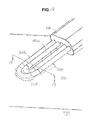
- FIG. 5 is a perspective view of an electrosurgical device according to the present invention.
- FIG. 6 is a plan view showing the various electrical connections and conductors of the device of FIG. 5 with the electro surgical unit of FIG. 1 ;
- FIG. 7 is a plan view showing a first embodiment of the various fluid connections and passages of the device of FIG. 5 with the electrosurgical unit and fluid source of FIG. 1 ;
- FIG. 8 is a plan view showing a second embodiment of the fluid connections and passages of the device of FIG. 5 with the electrosurgical unit and fluid source of FIG. 1 ;
- FIG. 9 is a close-up view of the shaft of the device of FIG. 5 ;
- FIG. 10 is a close-up cross-sectional view of the electrodes of the device of FIG. 5 . taken along line 10 - 10 of FIG. 5 ;
- FIG. 11 is a close-up cross-sectional view of another embodiment of the electrodes of the device of FIG. 5 taken along line 10 - 10 of FIG. 5 ;
- FIG. 12 is a close-up cross-sectional view of another embodiment of the electrodes of the device of FIG. 5 taken along line 10 - 10 of FIG. 5 ;
- FIG. 13 is a perspective view of the device of FIG. 5 cutting tissue
- FIG. 14 is a close-up view of a distal end portion of the device of FIG. 5 with an exemplary fluid coupling to a tissue surface of tissue;
- FIG. 15 is a perspective view of another embodiment of an electrosurgical device according to the present invention.
- FIG. 16 is a close-up view of the shaft of the device of FIG. 15 ;
- FIG. 17 is a close-up longitudinal cross-sectional view of the shaft of the device of FIG. 15 ;
- FIG. 18 is a close-up view of the electrodes of the device of FIG. 15 with an exemplary fluid coupling to a tissue surface of tissue;
- FIG. 19 is a close-up cross-sectional view of the device of FIG. 15 taken along line 19 - 19 with another view of a fluid coupling to a tissue surface of tissue;
- FIG. 20 is a close-up view of another embodiment of the fluid outlet(s) of the device of FIG. 15 ;
- FIG. 21 is a is a close-up view of another embodiment of the electrodes of the device of FIG. 15 ;
- FIG. 22 is a perspective view of a distal portion of another embodiment of an electrosurgical device according to the present invention.
- FIG. 23 is a perspective view of a distal portion of another embodiment of the electrosurgical device of FIG. 22 according to the present invention.
- FIG. 24 is a perspective view of a distal portion of another embodiment of an electrosurgical device according to the present invention.
- FIG. 25 is a perspective view of a distal portion of another embodiment of the electrosurgical device of FIG. 24 according to the present invention.
- the invention provides systems, devices and methods to control tissue temperature at a tissue treatment site during an electrosurgical procedure, as well as shrinking, coagulating, cutting and sealing tissue against blood and other fluid loss, for example, by shrinking the lumens of blood vessels (e.g., arteries, veins).
- the devices may be configured, due to the narrow electrode size, to fit through a trocar down to a size as small as 5 mm.
- FIG. 1 showing a front view of one embodiment of a system of the present invention which may include an electrosurgical unit 10 in combination with a fluid source 20 and a handheld electrosurgical device 30 .
- FIG. 1 shows a movable cart 2 having a support member 4 comprising a hollow cylindrical post which carries a platform 6 comprising a pedestal table to provide a flat, stable surface for location of the electrosurgical unit 10 .
- cart 2 further comprises a fluid source carrying pole 8 having a height which may be adjusted by sliding the carrying pole 8 up and down within the support member 4 and thereafter secured in position with a set screw.
- a fluid source carrying pole 8 On the top of the fluid source carrying pole 8 is a cross support provided with loops at the ends thereof to provide a hook for carrying fluid source 20 .
- fluid source 20 may comprise a bag of fluid from which fluid 12 may flow through a drip chamber 14 , particularly after the bag is penetrated with a spike located at the end of the drip chamber 14 . Thereafter, fluid 12 may flow through flexible and compressible fluid delivery tubing 16 to handheld electrosurgical device 30 .
- the fluid delivery tubing 16 may be made from a synthetic polymer material, such as polyvinyl chloride.
- pump 22 may comprise a peristaltic pump and, more specifically, a rotary peristaltic pump.
- a rotary peristaltic pump With a rotary peristaltic pump, a portion of the delivery tubing 16 may be loaded into the pump head by raising and lower the pump head in a known manner. Fluid 12 may then be conveyed within the delivery tubing 16 by waves of contraction placed externally on the tubing 16 which may be produced mechanically, typically by rotating pinch rollers which rotate on a drive shaft and intermittently compress the tubing 16 against an anvil support.
- Peristaltic pumps may be particularly used, as the electro-mechanical force mechanism, here rollers driven by electric motor, does not make contact the fluid 12 , thus reducing the likelihood of inadvertent contamination.
- the fluid 12 may particularly comprise liquid saline solution, and even more particularly, normal (0.9% w/v NaCl or physiologic) saline.
- saline normal (0.9% w/v NaCl or physiologic) saline.
- fluid 12 may also be an electrically non-conductive fluid.
- a non-conductive fluid while not providing all the advantage of an electrically conductive fluid, still provides certain advantages over the use of a dry electrode including, for example, reduced occurrence of tissue sticking to the electrode of device 30 and cooling of the electrode and/or tissue. Therefore, it is also within the scope of the invention to include the use of an electrically non-conductive fluid, such as, for example, deionized water.
- Electrosurgical unit 10 may be particularly configured to provide both monopolar and bipolar radio-frequency (RF) power output. However, electrosurgical unit 10 may particularly include a lock out feature which prevents both monopolar and bipolar output from being activated simultaneously.
- device 30 may be simultaneously connected to two separate electrosurgical units. For example, device 30 may be connected to a first electrosurgical unit 10 to provide monopolar power output thereto and a second electrosurgical unit 10 to provide bipolar power output thereto.
- a first electrode often referred to as the active electrode
- a second electrode often referred to as the indifferent or neutral electrode
- An electrical circuit may then be formed between the active electrode and ground pad dispersive electrode with electrical current flowing from the active electrode through the patient to ground pad dispersive electrode in a manner known in the art.
- the ground pad electrode located on the patient is not required, and a second electrode providing a second electrical pole may be provided as part of the device.
- An alternating current electrical circuit may then be created between the first and second electrical poles of the device. Consequently, alternating current no longer flows through the patient's body to the ground pad electrode, but rather through a localized portion of tissue between the poles of device 30 .
- monopolar and bipolar power may be provided from electrosurgical unit 10 as known in the art, or from separate electrosurgical units.
- electrosurgical device 30 may be connected to electrosurgical unit 10 via electrical cables 24 and 26 .
- Cable 24 is shown with a plug 34 which connects to bipolar output receptacle 38 of electrosurgical unit 10
- cable 26 is shown with a plug 42 which connects to the monopolar output receptacle 46 of electrosurgical unit 10 .
- additional cable 28 may connect a ground pad dispersive electrode 48 to the ground pad receptacle 56 of the electrosurgical unit 10 .
- FIG. 2 shows the front panel of exemplary electrosurgical unit 10 .
- a power switch 58 may be used to turn the electrosurgical unit 10 on and off.
- an RF power setting display 60 may be used to display the RF power setting numerically in watts.
- the power setting display 60 may further comprise a liquid crystal display (LCD).
- Electrosurgical unit 10 may further include an RF power selector 62 comprising RF power setting switches 62 a, 62 b which may be used to select the RF power setting. Pushing the switch 62 a may increase the RF power setting, while pushing the switch 62 b may decrease the RF power setting. Electrosurgical unit 10 may also include an RF power activation display 64 comprising an indicator light which may illuminate when RF power is activated, either via a handswitch on device 30 or a footswitch. Switches 62 a, 62 b may comprise membrane switches. It should be understood that while only one RF power selector 62 is shown, electrosurgical unit 10 may have two such RF power selectors with one each for monopolar and bipolar power selection.
- electrosurgical unit 10 may further include a fluid flow rate setting display 66 .
- Flow rate setting display 66 may comprise three indicator lights 66 a, 66 b and 66 c with first light 66 a corresponding to a fluid flow rate setting of low, second light 66 b corresponding to a fluid flow rate setting of medium (intermediate) and third light 66 c corresponding to a flow rate setting of high.
- first light 66 a corresponding to a fluid flow rate setting of low
- second light 66 b corresponding to a fluid flow rate setting of medium (intermediate)
- third light 66 c corresponding to a flow rate setting of high.
- One of these three indicator lights will illuminate when a fluid flow rate setting is selected.
- Electrosurgical unit 10 may further include a fluid flow selector 68 comprising flow rate setting switches 68 a, 68 b and 68 c used to select or switch the flow rate setting.
- a fluid flow selector 68 comprising flow rate setting switches 68 a, 68 b and 68 c used to select or switch the flow rate setting.
- Three push switches may be provided with first switch 68 a corresponding to the fluid flow rate setting of low, second switch 68 b corresponding to a fluid flow rate setting of medium (intermediate) and third switch 68 c corresponding to a flow rate setting of high. Pushing one of these three switches may select the corresponding flow rate setting of either low, medium (intermediate) or high.
- the medium, or intermediate, flow rate setting may be automatically selected as the default setting if no setting is manually selected.
- Switches 68 a, 68 b and 68 c may comprise membrane switches.
- a priming switch 70 may be used to initiate priming of device 30 with fluid 12 . Pushing switch 70 once may initiate operation of pump 22 for a predetermined time period to prime device 30 . After the time period is complete, the pump 22 may shut off automatically.
- a priming display 72 comprising an indicator light may illuminate during the priming cycle.
- FIG. 3 An exemplary bipolar RF power output curve of electrosurgical unit 10 is shown in FIG. 3 .
- Impedance Z shown in units of ohms on the X-axis and output power P O is shown in units of watts on the Y-axis.
- the bipolar electrosurgical power (RF) is set to 200 watts.
- the output power P O will remain constant with the set RF power P S as long as the impedance Z stays between the low impedance cut-off of 30 ohms and the high impedance cut-off of 120 ohms.
- an exemplary monopolar RF power output curve would include that of the Valleylab Force FX, either for cut or coagulation mode, hereby incorporated by reference.
- Electrosurgical unit 10 may be configured such that the speed of pump 22 , and therefore the throughput of fluid 12 expelled by the pump 22 , is predetermined based on two input variables, the RF power setting and the fluid flow rate setting.
- FIG. 4 there is shown an exemplary functional relationship of fluid flow rate Q in units of cubic centimetres per minute (cc/min) on the Y-axis, and the RF power setting P S in units of watts on the X-axis.
- the relationship may be engineered to inhibit undesirable effects such as tissue desiccation, electrode sticking, smoke production and char formation, while at the same time not providing a fluid flow rate Q at a corresponding RF power setting P S which is so great as to provide too much electrical dispersion and cooling at the electrode/tissue interface.
- electrosurgical unit 10 has been configured to increase the fluid flow rate Q linearly with an increasing RF power setting P S for each of three fluid flow rate settings of low, medium and high corresponding to Q L , Q M and Q H , respectively.
- electrosurgical unit 10 has been configured to decrease the fluid flow rate Q linearly with a decrease RF power setting P S for each of three fluid flow rate settings of low, medium and high corresponding to Q L , Q M and Q H , respectively.
- electrosurgical unit 10 as shown above includes an attached pump 22 , in other embodiments pump 22 may not be integrated with electrosurgical unit 10 , but rather be separate from electrosurgical unit 10 .
- pump 22 may be eliminated and there may be no preset functional relationship of fluid flow rate Q versus RF power setting P S stored in the electrosurgical unit 10 .
- the fluid flow rate Q may be manually controlled, such as by the user of device 10 or another member of the surgical team, with a roller (pinch) clamp or other clamp provided with device 10 and configured to act upon and compress the tubing 16 and control flow in a manner known in the art.
- Exemplary fluid flow control mechanisms may be found in U.S. Publication No. 2005/0090816, published Apr.
- An example of an electrosurgical unit which does not include a pump, but may be used in conjunction with a manually operated fluid flow control mechanism on device 10 , includes an electrosurgical unit such as the Valleylab Force FX.
- FIG. 5 An exemplary bipolar and/or monopolar electrosurgical device of the present invention which may be used in conjunction with electrosurgical unit 10 of the present invention is shown at reference character 30 a in FIG. 5 . While various electrosurgical devices of the present invention are described herein with reference to use with electrosurgical unit 10 , it should be understood that the description of the combination is for purposes of illustrating the system of the invention. Consequently, it should be understood that while the electrosurgical devices disclosed herein may be disclosed for use with electrosurgical unit 10 , it may be plausible to use other electrosurgical devices with electrosurgical unit 10 , or it may be plausible to use the electrosurgical devices disclosed herein with another electrosurgical unit.
- exemplary device 30 a includes an elongated handpiece 100 with a handle 101 comprising mating handle portions 101 a, 101 b.
- Handpiece 100 may be configured to enable a user of device 30 a to hold and manipulate device 30 a between the thumb and index finger like a writing instrument.
- Handle 101 may comprise a sterilizable, rigid, electrically insulative material, such as a synthetic polymer (e.g., polycarbonate, acrylonitrile-butadiene- styrene).
- Device 30 a further includes cables 24 and 26 , as shown in FIG. 1 , which are connectable to electrosurgical unit 10 to provide device 30 a with bipolar and monopolar power output, respectively, from electrosurgical unit 10 .
- cable 24 of device 30 a may comprise three insulated wire conductors 32 a, 32 b, 32 c connectable to bipolar power output receptacles 38 a, 38 b , 38 c of electrosurgical unit 10 via three banana (male) plug connectors 36 a, 36 b, 36 c .
- the banana plug connectors 36 a, 36 b, 36 c may be each assembled with insulated wire conductors 32 a, 32 b, 32 c within the housing of plug 34 in a known manner.
- insulated wire conductor 32 a may be connected to a bipolar hand switch assembly 110 , and insulated wire conductors 32 b and 32 c may be connected to a proximal portion of electrodes 102 a, 102 b, particularly by welding.
- Electrodes 102 a, 102 b thereafter may extend through linear conduits provided by cylindrical through passages 104 a, 104 b of elongated, rigid, electrically insulative shaft 108 comprising shaft body 106 .
- Shaft body 106 may comprise a sterilizable, rigid, electrically insulative material, such as a synthetic polymer (e.g., polycarbonate, acrylonitrile-butadiene-styrene).
- a distal portion of electrodes 102 a, 102 b having a U-shape loop extends from the passages 104 a, 104 b of elongated shaft body 106 .
- Cable 26 of device 30 a may comprise two insulated wire conductors 40 a, 40 b connectable to monopolar power output receptacles 46 a, 46 b of electrosurgical unit 10 via two banana (male) plug connectors 44 a, 44 b.
- the banana plug connectors 44 a , 44 b may be each assembled with insulated wire conductors 40 a, 40 b within the housing of plug 42 in a known manner.
- insulated wire conductor 40 a may be connected to a monopolar hand switch assembly 112
- insulated wire conductor 40 b may be connected to a proximal portion of electrode 102 b of shaft 108 .
- wire conductors 32 b and 40 b may merge inside handle 100 and share the same attachment location to electrode 102 b.
- an additional cable 28 may be utilized to connect a ground pad dispersive electrode 48 , which is attached to the patient, to the electrosurgical unit 10 comprising wire conductor 50 and plug 52 at the end thereof having plug connector 54 which connects to the ground pad receptacle 56 .
- Hand switch assemblies 110 and 112 may comprise push buttons 114 and 116 , respectively, which overlie domed switches on a platform comprising a printed circuit board, with the construction and wiring of the hand switch assemblies 110 and 112 known in the art.
- a domed switch beneath the push button forms a closed circuit which is sensed by electrosurgical unit 10 , which then provides bipolar or monopolar power, respectively.
- Exemplary hand switches may be found in U.S. Publication No. 2006/0149225, published Jul. 6, 2006, and U.S. Publication No. 2005/0090816, published Apr. 28, 2005, which are assigned to the assignee of the present invention and are hereby incorporated by reference in there entirety to the extent they are consistent.
- fluid 12 from fluid source 20 may be communicated through a tubular fluid passage provided by various structures.
- fluid 12 from the fluid source 20 is first communicated through lumen 18 of delivery tubing 16 .
- Fluid 12 may then flow through lumen 120 of a special pump tubing segment 118 configured to operate specifically with the peristaltic pump 22 , which may be spliced in between portions of delivery tubing 16 and connected thereto using barbed fluid line connectors 122 at each end thereof.
- fluid delivery tubing 16 may be connected to the inlet branch of a Y-splitter 124 , which thereafter provides two outlet branches which may be connected to the proximal end portion of delivery tubing segments 128 a, 128 b.
- a distal end portion of the delivery tubing segments 128 a, 128 b may be connected to shaft body 106 by being inserted into cylindrical receptacles 132 a, 132 b (counter bores) of shaft body 106 .
- Fluid 12 then may flow through lumens 130 a , 130 b of delivery tubing segments 128 a, 128 b and into tubular passages 134 a, 134 b formed in shaft body 106 . Fluid 12 may then be expelled from fluid delivery outlets 136 a, 136 b at the distal end 138 of shaft body 106 .
- fluid delivery tubing 16 may be inserted directly into receptacle 132 of shaft body 106 . Fluid 12 then may flow through passage 134 before branching into passages 134 a, 134 b within shaft body 106 and being expelled from fluid delivery outlets 136 a, 136 b. Also, alternatively, a single fluid outlet 136 may be located between the electrodes 102 a, 102 b, as shown in FIG. 10 , in which case outlets 136 a, 136 b may be omitted.
- FIG. 9 provides a close-up view of shaft body 106 , U-shaped electrodes 102 a , 102 b and fluid delivery outlets 136 a, 136 b.
- U-shaped electrodes 102 a , 102 b may be arranged to provide two fixed, laterally and spatially separated (by empty space) electrode tips which may be configured as mirror images in size and shape, and may have a blunt, rounded distal end which provides a smooth continuous surface (which is devoid of points or edges) to treat tissue.
- U-shaped electrodes 102 a, 102 b may be coplanar (i.e. in the same plane).
- U-shaped electrodes 102 a, 102 b which are adjacent the distal end 138 of shaft body 106 , may each comprise lateral longitudinal segments 140 a, 140 b and medial longitudinal segments 142 a, 142 b which extend distally from the distal end 138 of shaft body 106 and are proximal to an arcuate distal segments 144 a, 144 b.
- each electrode 102 a, 102 b may be particularly formed from a single continuous member, such as a single continuous piece of wire described in greater detail below.
- the arcuate distal segments are continuously arcuate from one longitudinal segment to the other longitudinal segment without any interruptions, and more particularly may be semicircular with a radius of 180 degrees.
- fluid delivery outlet 136 a is located between longitudinal segments 140 a, 142 a
- fluid delivery outlet 136 b is located between longitudinal segments 140 b, 142 b. In this manner, fluid 12 expelled from fluid delivery outlets 136 a, 136 b may better form a fluid membrane between longitudinal segments 140 a, 142 a and 140 b, 142 b , respectively, as discussed in greater detail below.
- the lateral longitudinal segments 140 a, 140 b extend through the length of shaft body 106 .
- the medial longitudinal segments 142 a, 142 b are retained in (e.g. interference/friction fit) and extend from a receptacles (blind bores) 146 a, 146 b formed in the distal end of shaft body 106 .
- lateral longitudinal segments 140 a, 140 b and medial longitudinal segments 142 a, 142 b are all parallel and coplanar (in the same plane).
- Electrodes 102 a, 102 b may particularly be formed from single strand, metal (particularly stainless steel) wire. Each electrode 102 a, 102 b may have an overall (exposed) length L in the range of and any increment between 4 mm to 15 mm, and more particularly 6 mm to 12 mm. Each electrode 102 a, 102 b may have a width W in the range of and any increment between 1 mm to 4 mm, and more particularly 2 mm to 3 mm.
- the wire may be cylindrical and have a circular cross-sectional profile with a cross-section thickness, here diameter, in a range of and any increment between 0.1 mm to 1.5 mm, and more particularly 0.5 mm to 1 mm, and even more particularly 0.6 to 0.75 mm.
- the spatial gap separation GS between electrodes 102 a, 102 b may be in the range of and any increment between 0.1 mm to 3 mm, and more particularly 0.5 mm to 2 mm, and even more particularly 0.75 mm to 1.5 mm.
- the spacing between the medial 142 a, 142 b and lateral segments 140 a, 140 b of each electrode 102 a, 102 b may be in a range of and any increment between 0.1 mm to 3 mm, and more particularly 0.5 mm to 2 mm, and even more particularly 0.75 mm to 1.5 mm.
- lateral longitudinal segment 140 b may be shaped, particularly from circular wire by grinding or sanding, as to have a cross-sectional profile with opposing sides 150 b / 152 b which converge laterally to provide a wedge shaped blade portion 154 b on the perimeter which terminates in a linear lateral cutting edge 156 b which extends longitudinally along the length of longitudinal segment 140 b.
- any of the remaining longitudinal segments 140 a, 142 a or 142 b may have the same cross-sectional profile as segment 140 b.
- blade portion 154 b narrows as the opposing sides 150 b / 152 b approach cutting edge 156 b. More particularly, the sides 150 b / 152 b of blade portion 154 b are planar. However, in other embodiments, sides 150 b / 152 b may be concave or convex.
- lateral longitudinal segment 140 b may be shaped, particularly from circular wire by grinding or sanding, as to have a profile with opposing sides 150 b / 152 b which are substantially parallel and terminate in linear lateral cutting edge 156 b which extends longitudinally along the length of longitudinal segment 140 b.
- any of the remaining longitudinal segments 140 a, 142 a or 142 b may have the same profile as segment 140 b.
- segment 140 has a polygonal profile, and more particularly a rectangular profile.
- lateral cutting edge 156 b may be particularly configured to cut tissue electrosurgically in the presence of monopolar radio frequency energy from electrosurgical unit 10 as to provide an electrosurgical cutting edge, but without any fluid 12 being provided from fluid source 20 .
- lateral cutting edge 156 b may be configured to cut tissue with fluid 12 being provided simultaneously from device 30 a , or be configured to cut tissue mechanically (sharpened) without electrosurgical energy.
- device 30 a may be used to cut tissue by applying cutting edge 156 b of electrode 102 b to tissue 200 , and repeatedly moving the electrode 102 b along a desired incision or resection line in the tissue to form the depicted crevice.
- arcuate distal end segments 144 a, 144 b may be particularly configured to slide or otherwise move across a tissue surface in the presence of bipolar radio frequency energy from electrosurgical unit 10 and fluid 12 from the fluid source 20 .
- one way in which device 30 a may be used as a bipolar device is with the longitudinal axis of electrodes 102 a, 102 b vertically orientated, and the arcuate distal segments 144 a, 144 b of electrodes 102 a, 102 b laterally spaced adjacent tissue surface 202 of tissue 200 .
- electrodes 102 a, 102 b may be connected to electrosurgical unit 10 and receive bipolar radio frequency energy which forms an alternating current electrical field in tissue 200 located between electrodes 102 a, 102 b.
- the electrodes 102 a, 102 b alternate polarity between positive and negative charges with current flow from the positive to negative charge.
- heating of the tissue is performed by electrical resistance heating.
- Fluid 12 in addition to providing an electrical coupling between the device 30 a and tissue 200 , lubricates surface 202 of tissue 200 and facilitates the movement of electrodes 102 a, 102 b across surface 202 of tissue 200 .
- electrodes 102 a, 102 b typically slide across the surface 202 of tissue 200 .
- the user of device 30 a slides electrodes 102 a, 102 b across surface 202 of tissue 200 back and forth with a painting motion while using fluid 12 as, among other things, a lubricating coating.
- the thickness of the fluid 12 between the arcuate distal segments 144 a, 144 b of electrodes 102 a, 102 b and surface 202 of tissue 200 at the outer edge of couplings 204 a, 204 b is in the range of 0.05 mm to 1.5 mm.
- the arcuate distal segments 144 a, 144 b of electrodes 102 a, 102 b may contact surface 202 of tissue 200 without any fluid 12 in between.
- fluid 12 expelled from fluid outlets 136 a, 136 b may flow distally on electrodes 102 a, 102 b in the form of droplets 208 a, 208 b or as a membrane 210 a, 210 b extending across the U-shaped apertures 160 a, 160 b and bridging between longitudinal segments 140 a , 142 a and 140 b , 142 b of electrodes 102 a , 102 b.
- droplets 208 a, 208 b may form at varying times from fluid 12 expelled from fluid outlets 136 a, 136 b.
- fluid 12 may be expelled in varying quantity from each of the fluid outlets 136 a, 136 b, depending on, for example, device orientation, pressure, flow rate and varying fluid outlet sizes.
- the physical characteristics of the droplets 208 a, 208 b and the membranes 210 a, 210 b may also vary due to changes in the surface finish of the electrodes 102 a, 102 b.
- the membranes 210 a, 210 b may form a meniscus type curvature at either end thereof as they progress distally along electrodes 102 a, 102 b.
- Fluid 12 in the form of membranes 210 a, 210 b bridging apertures 160 a, 160 b may offer certain advantages over droplets 208 , 208 b as the membranes 210 a, 210 b , after flowing distally along the longitudinal segments of electrodes 102 a, 102 b, may be more evenly distributed over arcuate distal segments 144 a, 144 b of electrodes 102 a, 102 b, to then form fluid couplings 204 a, 204 b.
- membranes 210 a, 210 b may exhibit better retention to electrodes 102 a, 102 b while flowing distally along electrodes 102 a, 102 b and not fall off as may be the situation for droplets 208 a, 208 b.
- fluid couplings 204 a, 204 b may particularly comprise discrete, localized webs and more specifically comprise triangular shaped webs of fluid 12 between surface 202 of tissue 200 and electrodes 102 a, 102 b.
- electrosurgical device 30 a places electrodes 102 a, 102 b at a tissue treatment site and moves electrodes 102 a, 102 b across the surface 202 of the tissue 200 , fluid 12 is expelled from fluid outlets 136 a, 136 b around the surfaces of electrodes 102 a, 102 b and onto the surface 202 of the tissue 200 via couplings 204 a, 204 b.
- RF electrical energy shown by electrical field lines 206 , is provided to tissue 200 at tissue surface 202 and below tissue surface 202 into tissue 200 through fluid couplings 204 a, 204 b.
- device 30 a may be used to seal tissue against blood and other fluid loss.
- arcuate distal end segments 144 a, 144 b may be particularly configured to slide or otherwise move across a tissue surface in the presence of bipolar radio frequency energy from electrosurgical unit 10 and fluid 12 from the fluid source 20 .
- FIGS. 15-18 Another embodiment of device 30 is shown in FIGS. 15-18 as device 30 b.
- the U-shaped electrodes are arranged such that the perimeter of U-shaped electrode 102 a is surrounded by U-shaped electrode 102 b, with U-shaped electrode 102 a located within the U-shaped aperture 160 b defined by electrode 102 b.
- the two longitudinal segments 140 a, 142 a of electrode 102 a are now medial to the two longitudinal segments 140 b, 142 b of electrode 102 b.
- the two longitudinal segments 140 b, 142 b of electrode 102 b are now lateral to the two longitudinal segments 140 a, 142 a of electrode 102 a.
- the electrode configuration of device 30 b may be somewhat narrower, which may make device 30 b less intrusive than device 30 a and afford device 30 b greater access to more confined locations with greater visibility.
- arcuate distal segments 144 a, 144 b of electrodes 102 a, 102 b may be concentric. In other words, arcuate distal segments 144 a, 144 b may have a common center point CP.
- U-shaped electrodes 102 a , 102 b are coplanar (in the same plane).
- longitudinal segments 140 a, 140 b and longitudinal segments 142 a, 142 b are all parallel and coplanar (in the same plane).
- U-shaped electrodes 102 a, 102 b may have the same cross-sectional profiles as set forth in FIGS. 10-12 . In this manner, electrode 102 b may still include cutting edge 156 b particularly configured to cut tissue with monopolar RF energy and without fluid 12 being expelled from device 30 b.
- one way in which device 30 b may be used as a bipolar device is with the longitudinal axis of electrodes 102 a, 102 b substantially horizontally orientated.
- electrodes 102 a , 102 b may be connected to electrosurgical unit 10 and receive bipolar radio frequency energy which forms an alternating current electrical field in tissue 200 located between electrodes 102 a, 102 b and fluid 12 provided from device 30 b.
- Fluid 12 in addition to providing an electrical coupling between the device 30 a and tissue 200 , lubricates surface 202 of tissue 200 and facilitates the movement of electrodes 102 a, 102 b across surface 202 of tissue 200 . As shown in FIGS. 18-19 , fluid 12 expelled from fluid outlet 136 may form fluid couplings 204 .
- fluid couplings 204 may particularly comprise localized webs and more specifically comprise triangular shaped webs of fluid 12 between surface 202 of tissue 200 and electrodes 102 a, 102 b.
- electrosurgical device 30 b places electrodes 102 a, 102 b at a tissue treatment site and moves electrodes 102 a, 102 b across the surface 202 of the tissue 200 , fluid 12 is expelled from fluid outlet 136 around the surfaces of electrodes 102 a, 102 b and onto the surface 202 of the tissue 200 via couplings 204 .
- RF electrical energy shown by electrical field lines 206 , is provided to tissue 200 at tissue surface 202 and below tissue surface 202 into tissue 200 through fluid couplings 204 .
- device 30 b may be used to seal tissue against blood and other fluid loss.
- fluid outlet 136 may be located between longitudinal segments 140 a, 142 a of electrodes 102 a. As shown in FIG. 20 , a fluid outlet 136 may be located between longitudinal segments 142 a of electrode 102 a and longitudinal segment 142 b of electrode 102 b. A fluid outlet 136 may also be located between longitudinal segments 140 a of electrode 102 a and longitudinal segment 140 b of electrode 102 b. In various embodiments, any fluid outlet 136 may be used individually or in combination with any other of fluid outlet(s) 136 as shown. For example, one or both of the fluid outlets 136 shown in FIG. 20 may be used in combination with the fluid outlet 136 shown in FIGS. 15-19 .
- outer electrode 102 b has the same cross-sectional profile with a thickness, here diameter, equal to the diameter of inner electrode 102 a.
- outer electrode 102 b may have a smaller cross-sectional profile with a thickness, here diameter, than inner electrode 102 a, to better facilitate cutting with a narrower incision, as well as better conforming to the tissue surface during sealing tissue, particularly by deforming when a slight pressure is applied by the user.
- electrode 102 a may comprise a single longitudinal segment 166 rather than having a U-shape. Similar to device 30 b, the perimeter of electrode 102 a is surrounded by U-shaped electrode 102 b, with electrode 102 a located within the U-shaped aperture 160 b defined by electrode 102 b. In this manner, the longitudinal segment 166 of electrode 102 a is medial to the two longitudinal segments 140 b, 142 b of electrode 102 b. Vice-versa, the two longitudinal segments 140 b, 142 b of electrode 102 b are lateral to longitudinal segment 166 of electrode 102 a. As compared with device 30 b , the electrode configuration of device 30 c may be somewhat narrower, which may make device 30 c less intrusive than device 30 b and afford device 30 c greater access to more confined locations with greater visibility.
- electrodes 102 a, 102 b are coplanar (in the same plane). Also similar to embodiments 30 a and 30 b, longitudinal segment 166 and longitudinal segments 142 a, 142 b are all parallel and coplanar (in the same plane). Also similar to embodiments 30 a and 30 b, electrodes 102 a, 102 b may have the same cross-sectional profiles as set forth in FIGS. 10-12 . In this manner, electrode 102 b may still include cutting edge 156 b particularly configured to cut tissue with monopolar RF energy and without fluid 12 being expelled from device 30 c.
- a fluid outlet 136 may be located between longitudinal segment 166 of electrode 102 a and longitudinal segment 142 b of electrode 102 b.
- a fluid outlet 136 may also be located between longitudinal segment 166 of electrode 102 a and longitudinal segment 140 b of electrode 102 b.
- Device 30 c may be used similar to device 30 b to cut and seal tissue as described herein.
- an electrical insulator 164 such as formed from a synthetic polymer (e.g.
- acetal may be located between the two electrodes 102 a , 102 b, and particularly between the distal end of electrode 102 a and the arcuate segment 144 b of electrode 102 b to better hold the position of the electrodes 102 a , 102 b relative to one another.
- electrode 102 a may take the form of a longitudinally orientated elongated blade shaped member 170 with a planar body, such as may be provided by a flattened portion of metal (e.g. stainless steel) tubing 172 which has been inserted in tubular passage 134 of shaft body 106 .
- metal e.g. stainless steel
- lumen 18 of fluid delivery tubing 16 may be in fluid communication with lumen 174 of metal tubing 172 such that fluid 12 may be expelled from fluid delivery outlet 136 adjacent the opposing sides 178 , 180 of the blade member 170 as defined by the tubing 172 , and insulated wire conductor 32 c may be connected to a proximal portion of the tubing, particularly by welding.
- blade member 170 of electrode 102 a may have a length in the range of and any increment between 4 mm to 15 mm, and more particularly 6 mm to 12 mm.
- Blade 145 may have a width in the range of and any increment between 1 mm to 4 mm, and more particularly 2 mm to 3 mm.
- the perimeter of electrode 102 a is surrounded by U-shaped electrode 102 b, with electrode 102 a located within the U-shaped aperture 160 b defined by electrode 102 b.
- the blade member 170 of electrode 102 a is medial to the two longitudinal segments 140 b, 142 b of electrode 102 b.
- the two longitudinal segments 140 b, 142 b of electrode 102 b are lateral to blade member 170 of electrode 102 a.
- electrodes 102 a, 102 b are coplanar (in the same plane). Also similar to embodiments 30 a - 30 c, blade member 170 and longitudinal segments 142 a, 142 b are all parallel and coplanar (in the same plane). Also similar to embodiments 30 a - 30 c, electrode 102 b may have the same cross-sectional profiles as set forth in FIGS. 10-12 . In this manner, electrode 102 b may still include cutting edge 156 b particularly configured to cut tissue with monopolar RF energy and without fluid 12 being expelled from device 30 c.
- the perimeter 176 of blade member 170 from one (top) side 178 to the other (bottom) side 180 may be semi-circular as shown, or may have an narrow or pointed edge 156 b as shown in either of FIG. 11 or 12 .
- the distal end 182 of blade member 170 is arcuate, and more particular semi-circular, across the width of the blade member 170 .
- the arcuate distal segment 144 b of electrode 102 b and the arcuate distal end 182 of blade member 170 may be concentric.
- the fluid outlet 136 may be orientated parallel with the longitudinal perimeter of the blade member 170 to better feed fluid 16 directly into aperture 160 b.
- device 30 d and particularly electrode 102 b may be expected to cut tissue in a similar manner.
- device 30 d may be able to seal larger areas of tissue from blood and other fluid loss by having an increased surface area of electrode 102 as provided by blade member 170 .
- Device 30 and the various embodiments disclosed herein, such as 30 a - 30 d may be particularly useful to surgeons to achieve hemostasis after cutting through soft tissue, as part of hip or knee arthroplasty.
- the electrodes 102 a, 102 b of device 30 may be moved with a painting motion over the raw, oozing surface 202 of tissue 200 to seal the tissue 200 against bleeding, or focused on individual larger bleeding vessels to stop vessel bleeding.
- device 30 may be useful to stop bleeding from the surface of cut bone, or osseous, tissue as part of any orthopaedic procedure that requires bone to be cut.
- Device 30 may be particularly useful for use during orthopedic knee, hip, shoulder and spine procedures. Additional discussion concerning such procedures may be found in U.S.
- Device 30 may be particularly useful as non-coaptive devices that provide cutting of tissue, as well as coagulation, hemostasis and sealing of tissue to inhibit blood and other fluid loss during surgery.
- grasping of the tissue is not necessary to shrink, coagulate, cut and seal tissue against blood loss, for example, by shrinking collagen and associated lumens of blood vessels (e.g., arteries, veins) to provided the desired hemostasis of the tissue.
- blood vessels e.g., arteries, veins
- the electrodes may be easily bent by a user of the devices as needed.
- the electrodes may also be used for other functions, such as providing a spoon like platform for scooping of tissue, such as an abnormal tissue mass (e.g. cancer).
- tissue such as an abnormal tissue mass (e.g. cancer).
- the control system of the electrosurgical unit 10 is not necessarily dependent on tissue feedback such as temperature or impedance to operate.
- the control system of electrosurgical unit 10 may be open loop with respect to the tissue which simplifies use.
- device 30 of the present invention inhibit such undesirable effects of tissue desiccation, electrode sticking, char formation and smoke generation, and thus do not suffer from the same drawbacks as prior art dry tip electrosurgical devices.
- the use of the disclosed devices can result in significantly lower blood loss during surgical procedures. Such a reduction in blood loss can reduce or eliminate the need for blood transfusions, and thus the cost and negative clinical consequences associated with blood transfusions, such as prolonged hospitalization.
Abstract
Description
- This invention relates generally to the field of medical devices, systems and methods for use upon a human body during surgery. More particularly, the invention relates to electrosurgical devices, systems and methods that provide for cutting of tissue in addition to coagulation, hemostasis and sealing of tissue to inhibit blood and other fluid loss during surgery such as abdominal, orthopedic, head, spine and thoracic surgery as well as general surgery of the body.
- Fluid-assisted electrosurgical devices have been developed which, when used in conjunction with an electrically conductive fluid such as saline, may be moved along a tissue surface, without cutting the tissue, to seal tissue to inhibit blood and other fluid loss during surgery. However, to cut tissue the surgeon must utilize a second device, which necessitates delays associated when switching between devices. What is still needed is an electrosurgical device which is capable of cutting of tissue as well as providing fluid-assisted sealing of tissue to inhibit blood and other fluid loss during surgery, as well as inhibit undesirable effects of tissue desiccation, tissue sticking to the electrode, tissue perforation, char formation and smoke generation. What is also needed is an electrosurgical device which cuts tissue with reduced lateral thermal spread and damage to adjacent tissue.
- The invention, in one embodiment, may provide an electrosurgical device to treat tissue in a presence of a fluid from a fluid source and radio-frequency power from a radio-frequency power source, particularly providing a bipolar power output and a monopolar power output. The device may comprise a distal portion comprising a first electrode tip, a second electrode tip and at least one fluid outlet. The first and second electrode tips may be configured as bipolar electrodes, configured to receive the bipolar power output from the radio-frequency power source treat tissue, particularly by moving along a tissue surface in a presence of a bipolar power output and a fluid provided simultaneously from the distal portion. At least one of the electrode tips may be configured as a monopolar electrode, configured to receive the monopolar power output from the radio-frequency power source and provide an electrosurgical cutting edge, which may be configured to cut tissue by moving along a tissue surface in a presence of monopolar power output provided from the distal portion.
- In certain embodiments, the electrosurgical device may comprise a handle, a shaft distal to the handle, a first electrode tip and a second electrode tip adjacent a distal end of the shaft, with the first electrode tip spaced from the second electrode tip and wherein the first electrode tip comprises a first wire electrode having a U-shape and the second electrode tip comprises a second wire electrode having a U-shape, and at least one fluid outlet.
- Each of the first and second U-shape electrodes may comprise an arcuate distal segment and two longitudinal segments extending distally relative to a distal end of the shaft. The arcuate distal segment of each of the first and second U-shape electrodes may be arcuate from one longitudinal segment to the other longitudinal segment, and may be semicircular between the two longitudinal segments. At least one of the U-shape electrodes may provide a cutting edge, which may be an electrosurgical cutting edge and may be arranged along a longitudinal length of the U-shape electrode. The cutting edge may particularly be straight (linear).
- The first electrode and a second electrode may be formed from metal wire. The metal wire may be single strand (solid core) wire, and more particularly circular single strand wire. The metal wire may be stainless steel wire. In this manner, the electrodes may have a low mass, which may allow the electrodes to dissipate heat and cool quickly during and after tissue treatment, which may inhibit damage to adjacent tissue (not to be treated) due to lateral thermal spread.
- The at least one fluid outlet may be located a distal end of the shaft. More particularly, the fluid outlet may be located between the two longitudinal segments of at least one of the U-shape electrodes.
- The at least one fluid outlet may comprise a first fluid outlet and second fluid outlet. The first fluid outlet may be located between the two longitudinal segments of the first U-shape electrode, and the second fluid outlet is located between the two longitudinal segments of the second U-shape electrode.
- The U-shape electrodes may be coplanar. The two longitudinal segments of the first U-shape electrode and the two longitudinal segments of the second U-shape electrode may be parallel, and more particularly in a single plane.
- One longitudinal segments of each of the first and second U-shape electrodes may be medial longitudinal segment and the other longitudinal segment may be lateral longitudinal segment.
- The two longitudinal segments of the second U-shape electrode may be medial relative to the two longitudinal segments of the first U-shape electrode.
- The first U-shape electrode may surround a perimeter of the second U-shape electrode, and the second U-shape electrode may be located within a U-shape aperture defined by the first U-shape electrode.
- Each of the first and second U-shape electrodes may comprise an arcuate distal segment, and the arcuate distal end segments may be concentric.
- The first U-shape electrode and the second U-shape electrode may have at least one of a same size and a same shape, and a position of first U-shape electrode and a position of the second U-shape electrode may be fixed relative to one another.
- In certain embodiments, the electrosurgical device may comprise a handle, a shaft distal to the handle, a first electrode tip and a second electrode tip adjacent a distal end of the shaft, with the first electrode tip spaced from the second electrode tip and wherein the first electrode tip comprises a first electrode having a first arcuate wire portion forming an arc of at least 180 degrees and the second electrode tip comprises a second electrode having a second arcuate wire portion forming an arc of at least 180 degrees, and at least one fluid outlet.
- In certain embodiments, the electrosurgical device may comprise a handle, a shaft distal to the handle, and a first electrode and a second electrode adjacent a distal end of the shaft with the first electrode coplanar with the second electrode and comprising a wire electrode having a U-shape which surrounds a perimeter of the second electrode and is spaced from the second electrode by an aperture. In certain embodiments, the second electrode may comprise a wire electrode having a linear segment, a U-shape or a blade shaped member. The device may also comprise at least one fluid outlet.
-
FIG. 1 is a front view of one embodiment of a system of the present invention having an electrosurgical unit in combination with a fluid source and handheld electrosurgical device; -
FIG. 2 a front perspective view of the electrosurgical unit ofFIG. 1 ; -
FIG. 3 is a graph of the bipolar RF power output versus impedance for the electrosurgical unit ofFIG. 1 ; -
FIG. 4 is graph showing a relationship of fluid flow rate Q in units of cubic centimetres per minute (cc/min) on the Y-axis, and the RF power setting PS in units of watts on the X-axis; -
FIG. 5 is a perspective view of an electrosurgical device according to the present invention; -
FIG. 6 is a plan view showing the various electrical connections and conductors of the device ofFIG. 5 with the electro surgical unit ofFIG. 1 ; -
FIG. 7 is a plan view showing a first embodiment of the various fluid connections and passages of the device ofFIG. 5 with the electrosurgical unit and fluid source ofFIG. 1 ; -
FIG. 8 is a plan view showing a second embodiment of the fluid connections and passages of the device ofFIG. 5 with the electrosurgical unit and fluid source ofFIG. 1 ; -
FIG. 9 is a close-up view of the shaft of the device ofFIG. 5 ; -
FIG. 10 is a close-up cross-sectional view of the electrodes of the device ofFIG. 5 . taken along line 10-10 ofFIG. 5 ; -
FIG. 11 is a close-up cross-sectional view of another embodiment of the electrodes of the device ofFIG. 5 taken along line 10-10 ofFIG. 5 ; -
FIG. 12 is a close-up cross-sectional view of another embodiment of the electrodes of the device ofFIG. 5 taken along line 10-10 ofFIG. 5 ; -
FIG. 13 is a perspective view of the device ofFIG. 5 cutting tissue; -
FIG. 14 is a close-up view of a distal end portion of the device ofFIG. 5 with an exemplary fluid coupling to a tissue surface of tissue; -
FIG. 15 is a perspective view of another embodiment of an electrosurgical device according to the present invention; -
FIG. 16 is a close-up view of the shaft of the device ofFIG. 15 ; -
FIG. 17 is a close-up longitudinal cross-sectional view of the shaft of the device ofFIG. 15 ; -
FIG. 18 is a close-up view of the electrodes of the device ofFIG. 15 with an exemplary fluid coupling to a tissue surface of tissue; -
FIG. 19 is a close-up cross-sectional view of the device ofFIG. 15 taken along line 19-19 with another view of a fluid coupling to a tissue surface of tissue; -
FIG. 20 is a close-up view of another embodiment of the fluid outlet(s) of the device ofFIG. 15 ; -
FIG. 21 is a is a close-up view of another embodiment of the electrodes of the device ofFIG. 15 ; -
FIG. 22 is a perspective view of a distal portion of another embodiment of an electrosurgical device according to the present invention; -
FIG. 23 is a perspective view of a distal portion of another embodiment of the electrosurgical device ofFIG. 22 according to the present invention; -
FIG. 24 is a perspective view of a distal portion of another embodiment of an electrosurgical device according to the present invention; and -
FIG. 25 is a perspective view of a distal portion of another embodiment of the electrosurgical device ofFIG. 24 according to the present invention. - Throughout the description, like reference numerals and letters indicate corresponding structure throughout the several views. Also, any particular feature(s) of a particular exemplary embodiment may be equally applied to any other exemplary embodiment(s) of this specification as suitable. In other words, features between the various exemplary embodiments described herein are interchangeable as suitable, and not exclusive. From the specification, it should be clear that any use of the terms “distal” and “proximal” are made in reference to the user of the device, and not the patient.
- The invention provides systems, devices and methods to control tissue temperature at a tissue treatment site during an electrosurgical procedure, as well as shrinking, coagulating, cutting and sealing tissue against blood and other fluid loss, for example, by shrinking the lumens of blood vessels (e.g., arteries, veins). The devices may be configured, due to the narrow electrode size, to fit through a trocar down to a size as small as 5 mm.
- The invention will now be discussed with reference to the figures, with
FIG. 1 showing a front view of one embodiment of a system of the present invention which may include anelectrosurgical unit 10 in combination with afluid source 20 and a handheldelectrosurgical device 30. In addition,FIG. 1 shows amovable cart 2 having a support member 4 comprising a hollow cylindrical post which carries a platform 6 comprising a pedestal table to provide a flat, stable surface for location of theelectrosurgical unit 10. - As shown,
cart 2 further comprises a fluidsource carrying pole 8 having a height which may be adjusted by sliding thecarrying pole 8 up and down within the support member 4 and thereafter secured in position with a set screw. On the top of the fluidsource carrying pole 8 is a cross support provided with loops at the ends thereof to provide a hook for carryingfluid source 20. - As shown in
FIG. 1 ,fluid source 20 may comprise a bag of fluid from whichfluid 12 may flow through a drip chamber 14, particularly after the bag is penetrated with a spike located at the end of the drip chamber 14. Thereafter, fluid 12 may flow through flexible and compressiblefluid delivery tubing 16 to handheldelectrosurgical device 30. Thefluid delivery tubing 16 may be made from a synthetic polymer material, such as polyvinyl chloride. - As shown in
FIG. 1 , thefluid delivery tubing 16 passes throughpump 22. As shown, pump 22 may comprise a peristaltic pump and, more specifically, a rotary peristaltic pump. With a rotary peristaltic pump, a portion of thedelivery tubing 16 may be loaded into the pump head by raising and lower the pump head in a known manner.Fluid 12 may then be conveyed within thedelivery tubing 16 by waves of contraction placed externally on thetubing 16 which may be produced mechanically, typically by rotating pinch rollers which rotate on a drive shaft and intermittently compress thetubing 16 against an anvil support. Peristaltic pumps may be particularly used, as the electro-mechanical force mechanism, here rollers driven by electric motor, does not make contact the fluid 12, thus reducing the likelihood of inadvertent contamination. - In the present embodiment the fluid 12 may particularly comprise liquid saline solution, and even more particularly, normal (0.9% w/v NaCl or physiologic) saline. Although the description herein may make reference to saline as the fluid 12, other electrically conductive fluids may be used in accordance with the invention.
- Additionally, while an electrically conductive fluid having an electrically conductivity similar to normal saline may be preferred, as will become more apparent with further reading of this specification, fluid 12 may also be an electrically non-conductive fluid. The use of a non-conductive fluid, while not providing all the advantage of an electrically conductive fluid, still provides certain advantages over the use of a dry electrode including, for example, reduced occurrence of tissue sticking to the electrode of
device 30 and cooling of the electrode and/or tissue. Therefore, it is also within the scope of the invention to include the use of an electrically non-conductive fluid, such as, for example, deionized water. -
Electrosurgical unit 10 may be particularly configured to provide both monopolar and bipolar radio-frequency (RF) power output. However,electrosurgical unit 10 may particularly include a lock out feature which prevents both monopolar and bipolar output from being activated simultaneously. Alternatively, rather than use asingle electrosurgical unit 10,device 30 may be simultaneously connected to two separate electrosurgical units. For example,device 30 may be connected to a firstelectrosurgical unit 10 to provide monopolar power output thereto and a secondelectrosurgical unit 10 to provide bipolar power output thereto. - During monopolar operation of
electrosurgical device 30, a first electrode, often referred to as the active electrode, may be provided withelectrosurgical device 30 while a second electrode, often referred to as the indifferent or neutral electrode, may be provided in the form of a ground pad dispersive electrode located on the patient (also known as a patient return electrode), typically on the back or other suitable anatomical location. An electrical circuit may then be formed between the active electrode and ground pad dispersive electrode with electrical current flowing from the active electrode through the patient to ground pad dispersive electrode in a manner known in the art. - During bipolar operation of
electrosurgical device 30, the ground pad electrode located on the patient is not required, and a second electrode providing a second electrical pole may be provided as part of the device. An alternating current electrical circuit may then be created between the first and second electrical poles of the device. Consequently, alternating current no longer flows through the patient's body to the ground pad electrode, but rather through a localized portion of tissue between the poles ofdevice 30. As indicated above, monopolar and bipolar power may be provided fromelectrosurgical unit 10 as known in the art, or from separate electrosurgical units. - As shown in
FIG. 1 ,electrosurgical device 30 may be connected toelectrosurgical unit 10 viaelectrical cables Cable 24 is shown with aplug 34 which connects tobipolar output receptacle 38 ofelectrosurgical unit 10, whilecable 26 is shown with aplug 42 which connects to themonopolar output receptacle 46 ofelectrosurgical unit 10. Briefly turning toFIG. 6 , when electrosurgical 10 may be used in monopolar mode,additional cable 28 may connect a groundpad dispersive electrode 48 to theground pad receptacle 56 of theelectrosurgical unit 10. -
FIG. 2 shows the front panel of exemplaryelectrosurgical unit 10. Apower switch 58 may be used to turn theelectrosurgical unit 10 on and off. After turning theelectrosurgical unit 10 on, an RFpower setting display 60 may be used to display the RF power setting numerically in watts. Thepower setting display 60 may further comprise a liquid crystal display (LCD). -
Electrosurgical unit 10 may further include anRF power selector 62 comprising RF power setting switches 62 a, 62 b which may be used to select the RF power setting. Pushing theswitch 62 a may increase the RF power setting, while pushing theswitch 62 b may decrease the RF power setting.Electrosurgical unit 10 may also include an RFpower activation display 64 comprising an indicator light which may illuminate when RF power is activated, either via a handswitch ondevice 30 or a footswitch.Switches RF power selector 62 is shown,electrosurgical unit 10 may have two such RF power selectors with one each for monopolar and bipolar power selection. - In addition to having a RF
power setting display 60,electrosurgical unit 10 may further include a fluid flowrate setting display 66. Flowrate setting display 66 may comprise threeindicator lights -
Electrosurgical unit 10 may further include afluid flow selector 68 comprising flow rate setting switches 68 a, 68 b and 68 c used to select or switch the flow rate setting. Three push switches may be provided withfirst switch 68 a corresponding to the fluid flow rate setting of low,second switch 68 b corresponding to a fluid flow rate setting of medium (intermediate) andthird switch 68 c corresponding to a flow rate setting of high. Pushing one of these three switches may select the corresponding flow rate setting of either low, medium (intermediate) or high. The medium, or intermediate, flow rate setting may be automatically selected as the default setting if no setting is manually selected.Switches - Before starting a surgical procedure, it may be desirable to
prime device 30 withfluid 12. Priming may be desirable to inhibit RF power activation without the presence offluid 12. Apriming switch 70 may be used to initiate priming ofdevice 30 withfluid 12. Pushingswitch 70 once may initiate operation ofpump 22 for a predetermined time period toprime device 30. After the time period is complete, thepump 22 may shut off automatically. When priming ofdevice 30 is initiated, apriming display 72 comprising an indicator light may illuminate during the priming cycle. - An exemplary bipolar RF power output curve of
electrosurgical unit 10 is shown inFIG. 3 . Impedance Z, shown in units of ohms on the X-axis and output power PO is shown in units of watts on the Y-axis. In the illustrated embodiment, the bipolar electrosurgical power (RF) is set to 200 watts. As shown in the figure, for an RF power setting PS of 200 watts, the output power PO will remain constant with the set RF power PS as long as the impedance Z stays between the low impedance cut-off of 30 ohms and the high impedance cut-off of 120 ohms. Below an impedance Z of 30 ohms, the output power PO will decrease as shown by the low impedance ramp. Above an impedance Z of 120 ohms, the output power PO will also decrease as shown by the high impedance ramp. With respect to monopolar power output, an exemplary monopolar RF power output curve would include that of the Valleylab Force FX, either for cut or coagulation mode, hereby incorporated by reference. -
Electrosurgical unit 10 may be configured such that the speed ofpump 22, and therefore the throughput offluid 12 expelled by thepump 22, is predetermined based on two input variables, the RF power setting and the fluid flow rate setting. InFIG. 4 there is shown an exemplary functional relationship of fluid flow rate Q in units of cubic centimetres per minute (cc/min) on the Y-axis, and the RF power setting PS in units of watts on the X-axis. The relationship may be engineered to inhibit undesirable effects such as tissue desiccation, electrode sticking, smoke production and char formation, while at the same time not providing a fluid flow rate Q at a corresponding RF power setting PS which is so great as to provide too much electrical dispersion and cooling at the electrode/tissue interface. While not being bound to a particular theory, a more detailed discussion on how the fluid flow rate interacts with the radio frequency power, modes of heat transfer away from the tissue, fractional boiling of the fluid and various control strategies may be found in U.S. Publication No. 2001/0032002, published Oct. 18, 2001, assigned to the assignee of the present invention and hereby incorporated by reference in its entirety to the extent it is consistent. - As shown in
FIG. 4 ,electrosurgical unit 10 has been configured to increase the fluid flow rate Q linearly with an increasing RF power setting PS for each of three fluid flow rate settings of low, medium and high corresponding to QL, QM and QH, respectively. Conversely,electrosurgical unit 10 has been configured to decrease the fluid flow rate Q linearly with a decrease RF power setting PS for each of three fluid flow rate settings of low, medium and high corresponding to QL, QM and QH, respectively. - An electrosurgical unit similar to exemplary
electrosurgical unit 10 and having detailed schematic drawings, albeit without monopolar output, may be found in U.S. Publication No. 2006/0149225, published Jul. 6, 2006, assigned to the assignee of the present invention and hereby incorporated by reference in its entirety to the extent it is consistent. - While
electrosurgical unit 10 as shown above includes an attachedpump 22, in other embodiments pump 22 may not be integrated withelectrosurgical unit 10, but rather be separate fromelectrosurgical unit 10. - In still other embodiments, pump 22 may be eliminated and there may be no preset functional relationship of fluid flow rate Q versus RF power setting PS stored in the
electrosurgical unit 10. In such an instance, rather than the fluid flow rate Q being automatically controlled by theelectrosurgical unit 10 based on the RF power setting PS, the fluid flow rate Q may be manually controlled, such as by the user ofdevice 10 or another member of the surgical team, with a roller (pinch) clamp or other clamp provided withdevice 10 and configured to act upon and compress thetubing 16 and control flow in a manner known in the art. Exemplary fluid flow control mechanisms may be found in U.S. Publication No. 2005/0090816, published Apr. 28, 2005, assigned to the assignee of the present invention and hereby incorporated by reference in its entirety to the extent it is consistent. An example of an electrosurgical unit which does not include a pump, but may be used in conjunction with a manually operated fluid flow control mechanism ondevice 10, includes an electrosurgical unit such as the Valleylab Force FX. - An exemplary bipolar and/or monopolar electrosurgical device of the present invention which may be used in conjunction with
electrosurgical unit 10 of the present invention is shown atreference character 30 a inFIG. 5 . While various electrosurgical devices of the present invention are described herein with reference to use withelectrosurgical unit 10, it should be understood that the description of the combination is for purposes of illustrating the system of the invention. Consequently, it should be understood that while the electrosurgical devices disclosed herein may be disclosed for use withelectrosurgical unit 10, it may be plausible to use other electrosurgical devices withelectrosurgical unit 10, or it may be plausible to use the electrosurgical devices disclosed herein with another electrosurgical unit. - As shown in
FIG. 5 ,exemplary device 30 a includes anelongated handpiece 100 with ahandle 101 comprising mating handle portions 101 a, 101 b.Handpiece 100 may be configured to enable a user ofdevice 30 a to hold and manipulatedevice 30 a between the thumb and index finger like a writing instrument. Handle 101 may comprise a sterilizable, rigid, electrically insulative material, such as a synthetic polymer (e.g., polycarbonate, acrylonitrile-butadiene- styrene). -
Device 30 a further includescables FIG. 1 , which are connectable toelectrosurgical unit 10 to providedevice 30 a with bipolar and monopolar power output, respectively, fromelectrosurgical unit 10. As further shown inFIG. 6 ,cable 24 ofdevice 30 a may comprise threeinsulated wire conductors electrosurgical unit 10 via three banana (male)plug connectors 36 a, 36 b, 36 c. Thebanana plug connectors 36 a, 36 b, 36 c may be each assembled withinsulated wire conductors plug 34 in a known manner. Ondevice 30 a,insulated wire conductor 32 a may be connected to a bipolarhand switch assembly 110, andinsulated wire conductors electrodes -
Electrodes insulative shaft 108 comprisingshaft body 106.Shaft body 106 may comprise a sterilizable, rigid, electrically insulative material, such as a synthetic polymer (e.g., polycarbonate, acrylonitrile-butadiene-styrene). At the distal end ofdevice 30, a distal portion ofelectrodes elongated shaft body 106. -
Cable 26 ofdevice 30 a may comprise two insulated wire conductors 40 a, 40 b connectable to monopolar power output receptacles 46 a, 46 b ofelectrosurgical unit 10 via two banana (male) plug connectors 44 a, 44 b. The banana plug connectors 44 a, 44 b may be each assembled with insulated wire conductors 40 a, 40 b within the housing ofplug 42 in a known manner. Ondevice 30 a, insulated wire conductor 40 a may be connected to a monopolarhand switch assembly 112, and insulated wire conductor 40 b may be connected to a proximal portion ofelectrode 102 b ofshaft 108. As shownwire conductors 32 b and 40 b may merge inside handle 100 and share the same attachment location to electrode 102 b. - When
device 30 a is used in monopolar mode, anadditional cable 28 may be utilized to connect a groundpad dispersive electrode 48, which is attached to the patient, to theelectrosurgical unit 10 comprisingwire conductor 50 and plug 52 at the end thereof havingplug connector 54 which connects to theground pad receptacle 56. -
Hand switch assemblies push buttons hand switch assemblies push buttons electrosurgical unit 10, which then provides bipolar or monopolar power, respectively. Exemplary hand switches may be found in U.S. Publication No. 2006/0149225, published Jul. 6, 2006, and U.S. Publication No. 2005/0090816, published Apr. 28, 2005, which are assigned to the assignee of the present invention and are hereby incorporated by reference in there entirety to the extent they are consistent. - As shown
FIG. 7 , during use ofdevice 30 a, fluid 12 fromfluid source 20 may be communicated through a tubular fluid passage provided by various structures. In the present embodiment, fluid 12 from thefluid source 20 is first communicated throughlumen 18 ofdelivery tubing 16.Fluid 12 may then flow throughlumen 120 of a specialpump tubing segment 118 configured to operate specifically with theperistaltic pump 22, which may be spliced in between portions ofdelivery tubing 16 and connected thereto using barbedfluid line connectors 122 at each end thereof. - Within
handle 101 ofdevice 30 a,fluid delivery tubing 16 may be connected to the inlet branch of a Y-splitter 124, which thereafter provides two outlet branches which may be connected to the proximal end portion of delivery tubing segments 128 a, 128 b. A distal end portion of the delivery tubing segments 128 a, 128 b may be connected toshaft body 106 by being inserted intocylindrical receptacles 132 a, 132 b (counter bores) ofshaft body 106.Fluid 12 then may flow through lumens 130 a, 130 b of delivery tubing segments 128 a, 128 b and intotubular passages 134 a, 134 b formed inshaft body 106.Fluid 12 may then be expelled fromfluid delivery outlets 136 a, 136 b at the distal end 138 ofshaft body 106. - Alternatively, as shown in
FIG. 8 ,fluid delivery tubing 16 may be inserted directly intoreceptacle 132 ofshaft body 106.Fluid 12 then may flow throughpassage 134 before branching intopassages 134 a, 134 b withinshaft body 106 and being expelled fromfluid delivery outlets 136 a, 136 b. Also, alternatively, asingle fluid outlet 136 may be located between theelectrodes FIG. 10 , in whichcase outlets 136 a, 136 b may be omitted. -
FIG. 9 provides a close-up view ofshaft body 106,U-shaped electrodes fluid delivery outlets 136 a, 136 b. As shown,U-shaped electrodes U-shaped electrodes -
U-shaped electrodes shaft body 106, may each comprise lateral longitudinal segments 140 a, 140 b and mediallongitudinal segments 142 a, 142 b which extend distally from the distal end 138 ofshaft body 106 and are proximal to an arcuate distal segments 144 a, 144 b. It should be understood that while theelectrodes electrodes electrode - As shown, the arcuate distal segments are continuously arcuate from one longitudinal segment to the other longitudinal segment without any interruptions, and more particularly may be semicircular with a radius of 180 degrees. Also as shown,
fluid delivery outlet 136 a is located between longitudinal segments 140 a, 142 a, and fluid delivery outlet 136 b is located betweenlongitudinal segments 140 b, 142 b. In this manner, fluid 12 expelled fromfluid delivery outlets 136 a, 136 b may better form a fluid membrane betweenlongitudinal segments 140 a, 142 a and 140 b, 142 b, respectively, as discussed in greater detail below. - Returning to
FIG. 7 , the lateral longitudinal segments 140 a, 140 b extend through the length ofshaft body 106. However, the mediallongitudinal segments 142 a, 142 b are retained in (e.g. interference/friction fit) and extend from a receptacles (blind bores) 146 a, 146 b formed in the distal end ofshaft body 106. As shown in the figures, lateral longitudinal segments 140 a, 140 b and mediallongitudinal segments 142 a, 142 b are all parallel and coplanar (in the same plane). -
Electrodes electrode electrode - As shown in
FIG. 10 , the wire may be cylindrical and have a circular cross-sectional profile with a cross-section thickness, here diameter, in a range of and any increment between 0.1 mm to 1.5 mm, and more particularly 0.5 mm to 1 mm, and even more particularly 0.6 to 0.75 mm. - With respect to spacing, the spatial gap separation GS between
electrodes electrode - As shown in
FIG. 11 , at least a portion of the length of lateral longitudinal segment 140 b may be shaped, particularly from circular wire by grinding or sanding, as to have a cross-sectional profile with opposing sides 150 b/152 b which converge laterally to provide a wedge shaped blade portion 154 b on the perimeter which terminates in a linear lateral cutting edge 156 b which extends longitudinally along the length of longitudinal segment 140 b. As shown, in alternative embodiments, any of the remaininglongitudinal segments 140 a, 142 a or 142 b may have the same cross-sectional profile as segment 140 b. - As shown in
FIG. 11 , blade portion 154 b narrows as the opposing sides 150 b/152 b approach cutting edge 156 b. More particularly, the sides 150 b/152 b of blade portion 154 b are planar. However, in other embodiments, sides 150 b/152 b may be concave or convex. - As shown in
FIG. 12 , at least a portion of the length of lateral longitudinal segment 140 b may be shaped, particularly from circular wire by grinding or sanding, as to have a profile with opposing sides 150 b/152 b which are substantially parallel and terminate in linear lateral cutting edge 156 b which extends longitudinally along the length of longitudinal segment 140 b. As shown, in alternative embodiments, any of the remaininglongitudinal segments 140 a, 142 a or 142 b may have the same profile as segment 140 b. Here,segment 140 has a polygonal profile, and more particularly a rectangular profile. - For the
electrodes FIGS. 11 and 12 , lateral cutting edge 156 b may be particularly configured to cut tissue electrosurgically in the presence of monopolar radio frequency energy fromelectrosurgical unit 10 as to provide an electrosurgical cutting edge, but without any fluid 12 being provided fromfluid source 20. However, in other embodiments, lateral cutting edge 156 b may be configured to cut tissue withfluid 12 being provided simultaneously fromdevice 30 a, or be configured to cut tissue mechanically (sharpened) without electrosurgical energy. Referring now toFIG. 13 ,device 30 a may be used to cut tissue by applying cutting edge 156 b ofelectrode 102 b totissue 200, and repeatedly moving theelectrode 102 b along a desired incision or resection line in the tissue to form the depicted crevice. - While cutting edge 156 b may be particularly configured to cut tissue with monopolar RF energy and without
fluid 12 being expelled fromdevice 30 a, arcuate distal end segments 144 a, 144 b may be particularly configured to slide or otherwise move across a tissue surface in the presence of bipolar radio frequency energy fromelectrosurgical unit 10 and fluid 12 from thefluid source 20. - As shown in
FIG. 14 , one way in whichdevice 30 a may be used as a bipolar device is with the longitudinal axis ofelectrodes electrodes adjacent tissue surface 202 oftissue 200. Whendevice 30 a is used in this manner,electrodes electrosurgical unit 10 and receive bipolar radio frequency energy which forms an alternating current electrical field intissue 200 located betweenelectrodes electrodes -
Fluid 12, in addition to providing an electrical coupling between thedevice 30 a andtissue 200, lubricatessurface 202 oftissue 200 and facilitates the movement ofelectrodes surface 202 oftissue 200. During movement ofelectrodes electrodes surface 202 oftissue 200. Typically the user ofdevice 30 aslides electrodes surface 202 oftissue 200 back and forth with a painting motion while usingfluid 12 as, among other things, a lubricating coating. Preferably the thickness of the fluid 12 between the arcuate distal segments 144 a, 144 b ofelectrodes surface 202 oftissue 200 at the outer edge ofcouplings 204 a, 204 b is in the range of 0.05 mm to 1.5 mm. Also, in certain embodiments, the arcuate distal segments 144 a, 144 b ofelectrodes surface 202 oftissue 200 without any fluid 12 in between. - As shown in
FIG. 14 ,fluid 12 expelled fromfluid outlets 136 a, 136 b may flow distally onelectrodes longitudinal segments 140 a,142 a and 140 b,142 b ofelectrodes FIG. 14 , droplets 208 a, 208 b may form at varying times fromfluid 12 expelled fromfluid outlets 136 a, 136 b. Also, fluid 12 may be expelled in varying quantity from each of thefluid outlets 136 a, 136 b, depending on, for example, device orientation, pressure, flow rate and varying fluid outlet sizes. With use ofdevice 30 a, the physical characteristics of the droplets 208 a, 208 b and the membranes 210 a, 210 b may also vary due to changes in the surface finish of theelectrodes electrodes -
Fluid 12 in the form of membranes 210 a, 210 b bridging apertures 160 a, 160 b may offer certain advantages over droplets 208, 208 b as the membranes 210 a, 210 b, after flowing distally along the longitudinal segments ofelectrodes electrodes fluid couplings 204 a, 204 b. Also, membranes 210 a, 210 b may exhibit better retention toelectrodes electrodes - As shown in
FIG. 14 ,fluid couplings 204 a, 204 b may particularly comprise discrete, localized webs and more specifically comprise triangular shaped webs offluid 12 betweensurface 202 oftissue 200 andelectrodes electrosurgical device 30 aplaces electrodes electrodes surface 202 of thetissue 200, fluid 12 is expelled fromfluid outlets 136 a, 136 b around the surfaces ofelectrodes surface 202 of thetissue 200 viacouplings 204 a, 204 b. At the same time, RF electrical energy, shown byelectrical field lines 206, is provided totissue 200 attissue surface 202 and belowtissue surface 202 intotissue 200 throughfluid couplings 204 a, 204 b. In the foregoing manner,device 30 a may be used to seal tissue against blood and other fluid loss. - Thus, while cutting edge 156 b may be particularly configured to cut tissue with monopolar RF energy and without
fluid 12 being expelled fromdevice 30 a, arcuate distal end segments 144 a, 144 b may be particularly configured to slide or otherwise move across a tissue surface in the presence of bipolar radio frequency energy fromelectrosurgical unit 10 and fluid 12 from thefluid source 20. - Another embodiment of
device 30 is shown inFIGS. 15-18 as device 30 b. As shown, rather the U-shaped electrodes being spaced side-by-side as withembodiment 30 a, the U-shaped electrodes are arranged such that the perimeter ofU-shaped electrode 102 a is surrounded byU-shaped electrode 102 b, withU-shaped electrode 102 a located within the U-shaped aperture 160 b defined byelectrode 102 b. In this manner, the two longitudinal segments 140 a, 142 a ofelectrode 102 a are now medial to the twolongitudinal segments 140 b, 142 b ofelectrode 102 b. Vice-versa, the twolongitudinal segments 140 b, 142 b ofelectrode 102 b are now lateral to the two longitudinal segments 140 a, 142 a ofelectrode 102 a. As compared withdevice 30 a, the electrode configuration of device 30 b may be somewhat narrower, which may make device 30 b less intrusive thandevice 30 a and afford device 30 b greater access to more confined locations with greater visibility. - As shown arcuate distal segments 144 a, 144 b of
electrodes embodiment 30 a,U-shaped electrodes embodiment 30 a, longitudinal segments 140 a, 140 b andlongitudinal segments 142 a, 142 b are all parallel and coplanar (in the same plane). Also similar toembodiment 30 a,U-shaped electrodes FIGS. 10-12 . In this manner,electrode 102 b may still include cutting edge 156 b particularly configured to cut tissue with monopolar RF energy and withoutfluid 12 being expelled from device 30 b. - As shown in
FIGS. 18-19 , one way in which device 30 b may be used as a bipolar device is with the longitudinal axis ofelectrodes device 30 a is used in this manner,electrodes electrosurgical unit 10 and receive bipolar radio frequency energy which forms an alternating current electrical field intissue 200 located betweenelectrodes fluid 12 provided from device 30 b. -
Fluid 12, in addition to providing an electrical coupling between thedevice 30 a andtissue 200, lubricatessurface 202 oftissue 200 and facilitates the movement ofelectrodes surface 202 oftissue 200. As shown inFIGS. 18-19 ,fluid 12 expelled fromfluid outlet 136 may formfluid couplings 204. - As shown in
FIG. 19 ,fluid couplings 204 may particularly comprise localized webs and more specifically comprise triangular shaped webs offluid 12 betweensurface 202 oftissue 200 andelectrodes b places electrodes electrodes surface 202 of thetissue 200, fluid 12 is expelled fromfluid outlet 136 around the surfaces ofelectrodes surface 202 of thetissue 200 viacouplings 204. At the same time, RF electrical energy, shown byelectrical field lines 206, is provided totissue 200 attissue surface 202 and belowtissue surface 202 intotissue 200 throughfluid couplings 204. In the foregoing manner, device 30 b may be used to seal tissue against blood and other fluid loss. - As shown in
FIGS. 15-19 ,fluid outlet 136 may be located between longitudinal segments 140 a, 142 a ofelectrodes 102 a. As shown inFIG. 20 , afluid outlet 136 may be located between longitudinal segments 142 a ofelectrode 102 a andlongitudinal segment 142 b ofelectrode 102 b. Afluid outlet 136 may also be located between longitudinal segments 140 a ofelectrode 102 a and longitudinal segment 140 b ofelectrode 102 b. In various embodiments, anyfluid outlet 136 may be used individually or in combination with any other of fluid outlet(s) 136 as shown. For example, one or both of thefluid outlets 136 shown inFIG. 20 may be used in combination with thefluid outlet 136 shown inFIGS. 15-19 . - For the embodiment of device 30 b shown in
FIGS. 15-19 ,outer electrode 102 b has the same cross-sectional profile with a thickness, here diameter, equal to the diameter ofinner electrode 102 a. However, as shown inFIG. 21 ,outer electrode 102 b may have a smaller cross-sectional profile with a thickness, here diameter, thaninner electrode 102 a, to better facilitate cutting with a narrower incision, as well as better conforming to the tissue surface during sealing tissue, particularly by deforming when a slight pressure is applied by the user. - In another embodiment of the
device 30, shown asdevice 30 c inFIG. 22 ,electrode 102 a may comprise a singlelongitudinal segment 166 rather than having a U-shape. Similar to device 30 b, the perimeter ofelectrode 102 a is surrounded byU-shaped electrode 102 b, withelectrode 102 a located within the U-shaped aperture 160 b defined byelectrode 102 b. In this manner, thelongitudinal segment 166 ofelectrode 102 a is medial to the twolongitudinal segments 140 b, 142 b ofelectrode 102 b. Vice-versa, the twolongitudinal segments 140 b, 142 b ofelectrode 102 b are lateral tolongitudinal segment 166 ofelectrode 102 a. As compared with device 30 b, the electrode configuration ofdevice 30 c may be somewhat narrower, which may makedevice 30 c less intrusive than device 30 b and afforddevice 30 c greater access to more confined locations with greater visibility. - As shown, similar to
embodiments 30 a and 30 b,electrodes embodiments 30 a and 30 b,longitudinal segment 166 andlongitudinal segments 142 a, 142 b are all parallel and coplanar (in the same plane). Also similar toembodiments 30 a and 30 b,electrodes FIGS. 10-12 . In this manner,electrode 102 b may still include cutting edge 156 b particularly configured to cut tissue with monopolar RF energy and withoutfluid 12 being expelled fromdevice 30 c. - As shown in
FIG. 22 , afluid outlet 136 may be located betweenlongitudinal segment 166 ofelectrode 102 a andlongitudinal segment 142 b ofelectrode 102 b. Afluid outlet 136 may also be located betweenlongitudinal segment 166 ofelectrode 102 a and longitudinal segment 140 b ofelectrode 102 b.Device 30 c may be used similar to device 30 b to cut and seal tissue as described herein. In an alternative embodiment, as shown inFIG. 23 , anelectrical insulator 164, such as formed from a synthetic polymer (e.g. acetal), may be located between the twoelectrodes electrode 102 a and the arcuate segment 144 b ofelectrode 102 b to better hold the position of theelectrodes - In another embodiment of the
device 30, shown as device 30 d inFIG. 24 ,electrode 102 a may take the form of a longitudinally orientated elongated blade shapedmember 170 with a planar body, such as may be provided by a flattened portion of metal (e.g. stainless steel)tubing 172 which has been inserted intubular passage 134 ofshaft body 106. In this manner, lumen 18 offluid delivery tubing 16 may be in fluid communication withlumen 174 ofmetal tubing 172 such thatfluid 12 may be expelled fromfluid delivery outlet 136 adjacent the opposingsides 178, 180 of theblade member 170 as defined by thetubing 172, andinsulated wire conductor 32 c may be connected to a proximal portion of the tubing, particularly by welding. With regards to dimensions,blade member 170 ofelectrode 102 a may have a length in the range of and any increment between 4 mm to 15 mm, and more particularly 6 mm to 12 mm. Blade 145 may have a width in the range of and any increment between 1 mm to 4 mm, and more particularly 2 mm to 3 mm. - Similar to
devices 30 b and 30 c, the perimeter ofelectrode 102 a is surrounded byU-shaped electrode 102 b, withelectrode 102 a located within the U-shaped aperture 160 b defined byelectrode 102 b. In this manner, theblade member 170 ofelectrode 102 a is medial to the twolongitudinal segments 140 b, 142 b ofelectrode 102 b. Vice-versa, the twolongitudinal segments 140 b, 142 b ofelectrode 102 b are lateral toblade member 170 ofelectrode 102 a. - As shown, similar to
embodiments 30 a-30 c,electrodes embodiments 30 a-30 c,blade member 170 andlongitudinal segments 142 a, 142 b are all parallel and coplanar (in the same plane). Also similar toembodiments 30 a-30 c,electrode 102 b may have the same cross-sectional profiles as set forth inFIGS. 10-12 . In this manner,electrode 102 b may still include cutting edge 156 b particularly configured to cut tissue with monopolar RF energy and withoutfluid 12 being expelled fromdevice 30 c. - The
perimeter 176 ofblade member 170 from one (top) side 178 to the other (bottom)side 180 may be semi-circular as shown, or may have an narrow or pointed edge 156 b as shown in either ofFIG. 11 or 12. Also, as shown thedistal end 182 ofblade member 170 is arcuate, and more particular semi-circular, across the width of theblade member 170. Also as shown, the arcuate distal segment 144 b ofelectrode 102 b and the arcuatedistal end 182 ofblade member 170 may be concentric. As shown inFIG. 25 , thefluid outlet 136 may be orientated parallel with the longitudinal perimeter of theblade member 170 tobetter feed fluid 16 directly into aperture 160 b. - As compared to
devices 30 b and 30 c, device 30 d and particularlyelectrode 102 b may be expected to cut tissue in a similar manner. With regards to sealing tissue, device 30 d may be able to seal larger areas of tissue from blood and other fluid loss by having an increased surface area ofelectrode 102 as provided byblade member 170. -
Device 30 and the various embodiments disclosed herein, such as 30 a-30 d, may be particularly useful to surgeons to achieve hemostasis after cutting through soft tissue, as part of hip or knee arthroplasty. Theelectrodes device 30 may be moved with a painting motion over the raw, oozingsurface 202 oftissue 200 to seal thetissue 200 against bleeding, or focused on individual larger bleeding vessels to stop vessel bleeding. As part of the same or different procedure,device 30 may be useful to stop bleeding from the surface of cut bone, or osseous, tissue as part of any orthopaedic procedure that requires bone to be cut.Device 30 may be particularly useful for use during orthopedic knee, hip, shoulder and spine procedures. Additional discussion concerning such procedures may be found in U.S. Publication No. 2006/0149225, published Jul. 6, 2006, and U.S. Publication No. 2005/0090816, published Apr. 28, 2005, which are assigned to the assignee of the present invention and are hereby incorporated by reference in there entirety to the extent they are consistent. -
Device 30, and the various embodiments disclosed herein, such as 30 a-30 d, may be particularly useful as non-coaptive devices that provide cutting of tissue, as well as coagulation, hemostasis and sealing of tissue to inhibit blood and other fluid loss during surgery. In other words, grasping of the tissue is not necessary to shrink, coagulate, cut and seal tissue against blood loss, for example, by shrinking collagen and associated lumens of blood vessels (e.g., arteries, veins) to provided the desired hemostasis of the tissue. Furthermore, due to the configuration of the electrodes, the electrodes may be easily bent by a user of the devices as needed. The electrodes may also be used for other functions, such as providing a spoon like platform for scooping of tissue, such as an abnormal tissue mass (e.g. cancer). Furthermore, the control system of theelectrosurgical unit 10 is not necessarily dependent on tissue feedback such as temperature or impedance to operate. Thus, the control system ofelectrosurgical unit 10 may be open loop with respect to the tissue which simplifies use. - As established above,
device 30 of the present invention inhibit such undesirable effects of tissue desiccation, electrode sticking, char formation and smoke generation, and thus do not suffer from the same drawbacks as prior art dry tip electrosurgical devices. The use of the disclosed devices can result in significantly lower blood loss during surgical procedures. Such a reduction in blood loss can reduce or eliminate the need for blood transfusions, and thus the cost and negative clinical consequences associated with blood transfusions, such as prolonged hospitalization. - While a preferred embodiment of the present invention has been described, it should be understood that various changes, adaptations and modifications can be made therein without departing from the spirit of the invention and the scope of the appended claims. The scope of the invention should, therefore, be determined not with reference to the above description, but instead should be determined with reference to the appended claims along with their full scope of equivalents. Furthermore, it should be understood that the appended claims do not necessarily comprise the broadest scope of the invention which the Applicant is entitled to claim, or the only manner(s) in which the invention may be claimed, or that all recited features are necessary.
- All publications and patent documents cited in this application are incorporated by reference in their entirety for all purposes to the extent they are consistent.
Claims (31)
Priority Applications (8)
| Application Number | Priority Date | Filing Date | Title |
|---|---|---|---|
| US12/827,734 US8906012B2 (en) | 2010-06-30 | 2010-06-30 | Electrosurgical devices with wire electrode |
| CN2011800317232A CN103153221A (en) | 2010-06-30 | 2011-06-29 | Electrosurgical device with a u-shaped electrode and/or coplanar electrodes |
| PCT/US2011/042356 WO2012012173A1 (en) | 2010-06-30 | 2011-06-29 | Electrosurgical device with a u-shaped electrode and/or coplanar electrodes |
| EP11730834.6A EP2588016B1 (en) | 2010-06-30 | 2011-06-29 | Electrosurgical device with a u-shaped electrode |
| CA2802417A CA2802417A1 (en) | 2010-06-30 | 2011-06-29 | Electrosurgical device with a u-shaped electrode and/or coplanar electrodes |
| MX2012014097A MX2012014097A (en) | 2010-06-30 | 2011-06-29 | Electrosurgical device with a u-shaped electrode and/or coplanar electrodes. |
| US13/729,337 US8920417B2 (en) | 2010-06-30 | 2012-12-28 | Electrosurgical devices and methods of use thereof |
| US14/197,578 US9445858B2 (en) | 2010-06-30 | 2014-03-05 | Bipolar electrosurgical device |
Applications Claiming Priority (1)
| Application Number | Priority Date | Filing Date | Title |
|---|---|---|---|
| US12/827,734 US8906012B2 (en) | 2010-06-30 | 2010-06-30 | Electrosurgical devices with wire electrode |
Related Child Applications (1)
| Application Number | Title | Priority Date | Filing Date |
|---|---|---|---|
| PCT/US2011/042356 Continuation-In-Part WO2012012173A1 (en) | 2010-06-30 | 2011-06-29 | Electrosurgical device with a u-shaped electrode and/or coplanar electrodes |
Publications (2)
| Publication Number | Publication Date |
|---|---|
| US20120004657A1 true US20120004657A1 (en) | 2012-01-05 |
| US8906012B2 US8906012B2 (en) | 2014-12-09 |
Family
ID=44628215
Family Applications (1)
| Application Number | Title | Priority Date | Filing Date |
|---|---|---|---|
| US12/827,734 Active 2033-07-08 US8906012B2 (en) | 2010-06-30 | 2010-06-30 | Electrosurgical devices with wire electrode |
Country Status (6)
| Country | Link |
|---|---|
| US (1) | US8906012B2 (en) |
| EP (1) | EP2588016B1 (en) |
| CN (1) | CN103153221A (en) |
| CA (1) | CA2802417A1 (en) |
| MX (1) | MX2012014097A (en) |
| WO (1) | WO2012012173A1 (en) |
Cited By (31)
| Publication number | Priority date | Publication date | Assignee | Title |
|---|---|---|---|---|
| US20070049920A1 (en) * | 2000-03-06 | 2007-03-01 | Tissuelink Medical, Inc. | Fluid-Assisted Medical Devices, Fluid Delivery Systems and Controllers for Such Devices, and Methods |
| US20090222001A1 (en) * | 2007-12-28 | 2009-09-03 | Salient Surgical Technologies, Inc. | Fluid-Assisted Electrosurgical Devices, Methods and Systems |
| US20100198216A1 (en) * | 2009-02-02 | 2010-08-05 | Palanker Daniel V | Electro-thermotherapy of tissue using penetrating microelectrode array |
| US20110125146A1 (en) * | 2009-09-08 | 2011-05-26 | Salient Surgical Technologies, Inc. | Cartridge Assembly For Electrosurgical Devices, Electrosurgical Unit And Methods Of Use Thereof |
| US8632533B2 (en) | 2009-02-23 | 2014-01-21 | Medtronic Advanced Energy Llc | Fluid-assisted electrosurgical device |
| WO2014082068A2 (en) | 2012-11-26 | 2014-05-30 | Medtronic Advanced Energy Llc | Surgical device |
| US8870864B2 (en) | 2011-10-28 | 2014-10-28 | Medtronic Advanced Energy Llc | Single instrument electrosurgery apparatus and its method of use |
| US8906012B2 (en) | 2010-06-30 | 2014-12-09 | Medtronic Advanced Energy Llc | Electrosurgical devices with wire electrode |
| US8920417B2 (en) | 2010-06-30 | 2014-12-30 | Medtronic Advanced Energy Llc | Electrosurgical devices and methods of use thereof |
| US9023040B2 (en) | 2010-10-26 | 2015-05-05 | Medtronic Advanced Energy Llc | Electrosurgical cutting devices |
| US9131980B2 (en) | 2011-12-19 | 2015-09-15 | Medtronic Advanced Energy Llc | Electrosurgical devices |
| US9138289B2 (en) | 2010-06-28 | 2015-09-22 | Medtronic Advanced Energy Llc | Electrode sheath for electrosurgical device |
| US9226792B2 (en) | 2012-06-12 | 2016-01-05 | Medtronic Advanced Energy Llc | Debridement device and method |
| US9333027B2 (en) * | 2010-05-28 | 2016-05-10 | Medtronic Advanced Energy Llc | Method of producing an electrosurgical device |
| US9427281B2 (en) | 2011-03-11 | 2016-08-30 | Medtronic Advanced Energy Llc | Bronchoscope-compatible catheter provided with electrosurgical device |
| US9592090B2 (en) | 2010-03-11 | 2017-03-14 | Medtronic Advanced Energy Llc | Bipolar electrosurgical cutter with position insensitive return electrode contact |
| US9750565B2 (en) | 2011-09-30 | 2017-09-05 | Medtronic Advanced Energy Llc | Electrosurgical balloons |
| US9956029B2 (en) | 2014-10-31 | 2018-05-01 | Medtronic Advanced Energy Llc | Telescoping device with saline irrigation line |
| US9974599B2 (en) | 2014-08-15 | 2018-05-22 | Medtronic Ps Medical, Inc. | Multipurpose electrosurgical device |
| US10188456B2 (en) | 2015-02-18 | 2019-01-29 | Medtronic Xomed, Inc. | Electrode assembly for RF energy enabled tissue debridement device |
| US10194975B1 (en) | 2017-07-11 | 2019-02-05 | Medtronic Advanced Energy, Llc | Illuminated and isolated electrosurgical apparatus |
| US10314647B2 (en) | 2013-12-23 | 2019-06-11 | Medtronic Advanced Energy Llc | Electrosurgical cutting instrument |
| CN110051419A (en) * | 2019-04-29 | 2019-07-26 | 河北瑞鹤医疗器械有限公司 | Cut stick device in original position |
| US10376302B2 (en) | 2015-02-18 | 2019-08-13 | Medtronic Xomed, Inc. | Rotating electrical connector for RF energy enabled tissue debridement device |
| US10631914B2 (en) | 2013-09-30 | 2020-04-28 | Covidien Lp | Bipolar electrosurgical instrument with movable electrode and related systems and methods |
| US10716612B2 (en) | 2015-12-18 | 2020-07-21 | Medtronic Advanced Energy Llc | Electrosurgical device with multiple monopolar electrode assembly |
| US10813686B2 (en) | 2014-02-26 | 2020-10-27 | Medtronic Advanced Energy Llc | Electrosurgical cutting instrument |
| US11051875B2 (en) | 2015-08-24 | 2021-07-06 | Medtronic Advanced Energy Llc | Multipurpose electrosurgical device |
| US11207130B2 (en) | 2015-02-18 | 2021-12-28 | Medtronic Xomed, Inc. | RF energy enabled tissue debridement device |
| US11234760B2 (en) | 2012-10-05 | 2022-02-01 | Medtronic Advanced Energy Llc | Electrosurgical device for cutting and removing tissue |
| US11389227B2 (en) | 2015-08-20 | 2022-07-19 | Medtronic Advanced Energy Llc | Electrosurgical device with multivariate control |
Families Citing this family (8)
| Publication number | Priority date | Publication date | Assignee | Title |
|---|---|---|---|---|
| EP1435867B1 (en) | 2001-09-05 | 2010-11-17 | Salient Surgical Technologies, Inc. | Fluid-assisted medical devices and systems |
| EP3148466B1 (en) * | 2014-05-30 | 2022-07-27 | Bipad, Inc. | Bipolar electrosurgery actuator |
| US10751117B2 (en) | 2016-09-23 | 2020-08-25 | Ethicon Llc | Electrosurgical instrument with fluid diverter |
| JP7049326B2 (en) | 2016-10-04 | 2022-04-06 | アヴェント インコーポレイテッド | Cooled RF probe |
| US11497546B2 (en) | 2017-03-31 | 2022-11-15 | Cilag Gmbh International | Area ratios of patterned coatings on RF electrodes to reduce sticking |
| US11484358B2 (en) | 2017-09-29 | 2022-11-01 | Cilag Gmbh International | Flexible electrosurgical instrument |
| US11490951B2 (en) | 2017-09-29 | 2022-11-08 | Cilag Gmbh International | Saline contact with electrodes |
| US11033323B2 (en) | 2017-09-29 | 2021-06-15 | Cilag Gmbh International | Systems and methods for managing fluid and suction in electrosurgical systems |
Citations (13)
| Publication number | Priority date | Publication date | Assignee | Title |
|---|---|---|---|---|
| US5192280A (en) * | 1991-11-25 | 1993-03-09 | Everest Medical Corporation | Pivoting multiple loop bipolar cutting device |
| US5197964A (en) * | 1991-11-12 | 1993-03-30 | Everest Medical Corporation | Bipolar instrument utilizing one stationary electrode and one movable electrode |
| US5658280A (en) * | 1995-05-22 | 1997-08-19 | Issa; Muta M. | Resectoscope electrode assembly with simultaneous cutting and coagulation |
| US5855061A (en) * | 1996-06-05 | 1999-01-05 | Valley Forge Scientific Corporation | Method of making flat loop bipolar electrode tips for electrosurgical instrument |
| US5976129A (en) * | 1991-10-18 | 1999-11-02 | Desai; Ashvin H. | Endoscopic surgical instrument |
| US5980519A (en) * | 1996-07-30 | 1999-11-09 | Symbiosis Corporation | Electrocautery probe with variable morphology electrode |
| US6352533B1 (en) * | 1999-05-03 | 2002-03-05 | Alan G. Ellman | Electrosurgical handpiece for treating tissue |
| US6494881B1 (en) * | 1997-09-30 | 2002-12-17 | Scimed Life Systems, Inc. | Apparatus and method for electrode-surgical tissue removal having a selectively insulated electrode |
| US20030009164A1 (en) * | 1995-06-07 | 2003-01-09 | Arthrocare Corporation | Articulated electrosurgical probe |
| US20050251134A1 (en) * | 2004-05-07 | 2005-11-10 | Arthrocare Corporation | Apparatus and methods for electrosurgical ablation and resection of target tissue |
| US6991631B2 (en) * | 2000-06-09 | 2006-01-31 | Arthrocare Corporation | Electrosurgical probe having circular electrode array for ablating joint tissue and systems related thereto |
| US20110130757A1 (en) * | 2008-06-30 | 2011-06-02 | Celon Ag Medical Instruments | Electrosurgical instrument |
| US8608739B2 (en) * | 2008-07-22 | 2013-12-17 | Covidien Lp | Electrosurgical devices, systems and methods of using the same |
Family Cites Families (471)
| Publication number | Priority date | Publication date | Assignee | Title |
|---|---|---|---|---|
| US2888928A (en) | 1957-04-15 | 1959-06-02 | Seiger Harry Wright | Coagulating surgical instrument |
| US3682130A (en) | 1965-03-19 | 1972-08-08 | Jeffers & Bailey Inc | Fusible temperature responsive trigger device |
| US3750650A (en) | 1970-12-15 | 1973-08-07 | Hewlett Packard Gmbh | Double spiral electrode for intra-cavity attachment |
| US3823575A (en) | 1971-06-07 | 1974-07-16 | Univ Melbourne | Cryogenic apparatus |
| GB1438759A (en) | 1972-06-02 | 1976-06-09 | Spembly Ltd | Cryo-surgical apparatus |
| US3886945A (en) | 1972-06-14 | 1975-06-03 | Frigitronics Of Conn Inc | Cryosurgical apparatus |
| US3830239A (en) | 1972-09-12 | 1974-08-20 | Frigitronics Of Conn Inc | Cryosurgical device |
| US3823718A (en) | 1972-09-15 | 1974-07-16 | T Tromovitch | Portable cryosurgical apparatus |
| US3827436A (en) | 1972-11-10 | 1974-08-06 | Frigitronics Of Conn Inc | Multipurpose cryosurgical probe |
| US3924628A (en) | 1972-12-01 | 1975-12-09 | William Droegemueller | Cyrogenic bladder for necrosing tissue cells |
| NL176833C (en) | 1973-04-26 | 1985-06-17 | Draegerwerk Ag | HEAT-INSULATING FLEXIBLE PIPE. |
| US3859986A (en) | 1973-06-20 | 1975-01-14 | Jiro Okada | Surgical device |
| US3907339A (en) | 1973-07-23 | 1975-09-23 | Frigitronics Of Conn Inc | Cryogenic delivery line |
| US3862627A (en) | 1973-08-16 | 1975-01-28 | Sr Wendel J Hans | Suction electrode |
| US4022215A (en) | 1973-12-10 | 1977-05-10 | Benson Jerrel W | Cryosurgical system |
| GB1513565A (en) | 1975-04-22 | 1978-06-07 | Spembly Ltd | Cryosurgical instruments |
| US4018227A (en) | 1975-10-09 | 1977-04-19 | Cryomedics, Inc. | Cryosurgical instrument |
| US4060088A (en) | 1976-01-16 | 1977-11-29 | Valleylab, Inc. | Electrosurgical method and apparatus for establishing an electrical discharge in an inert gas flow |
| US4072152A (en) | 1976-02-23 | 1978-02-07 | Linehan John H | Orthopedic cryosurgical apparatus |
| GB1534162A (en) | 1976-07-21 | 1978-11-29 | Lloyd J | Cyosurgical probe |
| US4061135A (en) | 1976-09-27 | 1977-12-06 | Jerrold Widran | Binocular endoscope |
| DE2646229A1 (en) | 1976-10-13 | 1978-04-20 | Erbe Elektromedizin | HIGH FREQUENCY SURGICAL EQUIPMENT |
| US6603988B2 (en) | 2001-04-13 | 2003-08-05 | Kelsey, Inc. | Apparatus and method for delivering ablative laser energy and determining the volume of tumor mass destroyed |
| US4275734A (en) | 1977-08-12 | 1981-06-30 | Valleylab, Inc. | Cryosurgical apparatus and method |
| US4321931A (en) | 1978-04-10 | 1982-03-30 | Hon Edward D | Electrode structure and applicator therefor |
| DE2831199C3 (en) | 1978-07-15 | 1981-01-08 | Erbe Elektromedizin Gmbh & Co Kg, 7400 Tuebingen | Cryosurgical device |
| US4248224A (en) | 1978-08-01 | 1981-02-03 | Jones James W | Double venous cannula |
| US4276874A (en) | 1978-11-15 | 1981-07-07 | Datascope Corp. | Elongatable balloon catheter |
| US4342218A (en) | 1980-01-16 | 1982-08-03 | Forrest Fox | Method and apparatus for zeroing and calibrating an invasive blood pressure monitoring system |
| CA1129015A (en) | 1980-06-11 | 1982-08-03 | Timofei S. Gudkin | Thermoelectric cryoprobe |
| US4355642A (en) | 1980-11-14 | 1982-10-26 | Physio-Control Corporation | Multipolar electrode for body tissue |
| US4377168A (en) | 1981-02-27 | 1983-03-22 | Wallach Surgical Instruments, Inc. | Cryosurgical instrument |
| US4381007A (en) | 1981-04-30 | 1983-04-26 | The United States Of America As Represented By The United States Department Of Energy | Multipolar corneal-shaping electrode with flexible removable skirt |
| US4598698A (en) | 1983-01-20 | 1986-07-08 | Warner-Lambert Technologies, Inc. | Diagnostic device |
| US4601290A (en) | 1983-10-11 | 1986-07-22 | Cabot Medical Corporation | Surgical instrument for cutting body tissue from a body area having a restricted space |
| US5143073A (en) | 1983-12-14 | 1992-09-01 | Edap International, S.A. | Wave apparatus system |
| DE3490633T (en) | 1984-01-30 | 1985-12-12 | Char'kovskaja oblastnaja kliničeskaja bol'nica, Char'kov | Bipolar electrosurgical device |
| US4664110A (en) | 1985-03-18 | 1987-05-12 | University Of Southern California | Controlled rate freezing for cryorefractive surgery |
| SE8502048D0 (en) | 1985-04-26 | 1985-04-26 | Astra Tech Ab | VACUUM FIXED HALLS FOR MEDICAL USE |
| US4917095A (en) | 1985-11-18 | 1990-04-17 | Indianapolis Center For Advanced Research, Inc. | Ultrasound location and therapy method and apparatus for calculi in the body |
| US4872346A (en) | 1986-07-18 | 1989-10-10 | Indianapolis Center For Advanced Research | Multiple frequencies from single crystal |
| US5231995A (en) | 1986-11-14 | 1993-08-03 | Desai Jawahar M | Method for catheter mapping and ablation |
| US5044165A (en) | 1986-12-03 | 1991-09-03 | Board Of Regents, The University Of Texas | Cryo-slammer |
| US4779611A (en) | 1987-02-24 | 1988-10-25 | Grooters Ronald K | Disposable surgical scope guide |
| US4802475A (en) | 1987-06-22 | 1989-02-07 | Weshahy Ahmed H A G | Methods and apparatus of applying intra-lesional cryotherapy |
| US4943290A (en) | 1987-06-23 | 1990-07-24 | Concept Inc. | Electrolyte purging electrode tip |
| US4950232A (en) | 1987-08-11 | 1990-08-21 | Surelab Superior Research Laboratories | Cerebrospinal fluid shunt system |
| US4931047A (en) | 1987-09-30 | 1990-06-05 | Cavitron, Inc. | Method and apparatus for providing enhanced tissue fragmentation and/or hemostasis |
| US4815470A (en) | 1987-11-13 | 1989-03-28 | Advanced Diagnostic Medical Systems, Inc. | Inflatable sheath for ultrasound probe |
| US4919129A (en) | 1987-11-30 | 1990-04-24 | Celebration Medical Products, Inc. | Extendable electrocautery surgery apparatus and method |
| US5588432A (en) | 1988-03-21 | 1996-12-31 | Boston Scientific Corporation | Catheters for imaging, sensing electrical potentials, and ablating tissue |
| US5029574A (en) | 1988-04-14 | 1991-07-09 | Okamoto Industries, Inc. | Endoscopic balloon with a protective film thereon |
| US4998933A (en) | 1988-06-10 | 1991-03-12 | Advanced Angioplasty Products, Inc. | Thermal angioplasty catheter and method |
| US5147355A (en) | 1988-09-23 | 1992-09-15 | Brigham And Womens Hospital | Cryoablation catheter and method of performing cryoablation |
| GB8822492D0 (en) | 1988-09-24 | 1988-10-26 | Considine J | Apparatus for removing tumours from hollow organs of body |
| US5108390A (en) | 1988-11-14 | 1992-04-28 | Frigitronics, Inc. | Flexible cryoprobe |
| GB2226497B (en) | 1988-12-01 | 1992-07-01 | Spembly Medical Ltd | Cryosurgical probe |
| GB8829525D0 (en) | 1988-12-17 | 1989-02-01 | Spembly Medical Ltd | Cryosurgical apparatus |
| US4932952A (en) | 1988-12-20 | 1990-06-12 | Alto Development Corporation | Antishock, anticlog suction coagulator |
| US4936281A (en) | 1989-04-13 | 1990-06-26 | Everest Medical Corporation | Ultrasonically enhanced RF ablation catheter |
| US4946460A (en) | 1989-04-26 | 1990-08-07 | Cryo Instruments, Inc. | Apparatus for cryosurgery |
| US4916922A (en) | 1989-05-09 | 1990-04-17 | Mullens Patrick L | Rapid freezing apparatus |
| DE3917328A1 (en) | 1989-05-27 | 1990-11-29 | Wolf Gmbh Richard | BIPOLAR COAGULATION INSTRUMENT |
| US5516505A (en) | 1989-07-18 | 1996-05-14 | Mcdow; Ronald A. | Method for using cryogenic agents for treating skin lesions |
| US5100388A (en) | 1989-09-15 | 1992-03-31 | Interventional Thermodynamics, Inc. | Method and device for thermal ablation of hollow body organs |
| GB9004427D0 (en) | 1990-02-28 | 1990-04-25 | Nat Res Dev | Cryogenic cooling apparatus |
| US5013312A (en) | 1990-03-19 | 1991-05-07 | Everest Medical Corporation | Bipolar scalpel for harvesting internal mammary artery |
| US5080660A (en) | 1990-05-11 | 1992-01-14 | Applied Urology, Inc. | Electrosurgical electrode |
| ZA917281B (en) | 1990-09-26 | 1992-08-26 | Cryomedical Sciences Inc | Cryosurgical instrument and system and method of cryosurgery |
| US5190541A (en) | 1990-10-17 | 1993-03-02 | Boston Scientific Corporation | Surgical instrument and method |
| US5269291A (en) | 1990-12-10 | 1993-12-14 | Coraje, Inc. | Miniature ultrasonic transducer for plaque ablation |
| US5324255A (en) | 1991-01-11 | 1994-06-28 | Baxter International Inc. | Angioplasty and ablative devices having onboard ultrasound components and devices and methods for utilizing ultrasound to treat or prevent vasopasm |
| EP0570520A1 (en) | 1991-02-06 | 1993-11-24 | Laparomed Corporation | Electrosurgical device |
| US5465717A (en) | 1991-02-15 | 1995-11-14 | Cardiac Pathways Corporation | Apparatus and Method for ventricular mapping and ablation |
| US5316000A (en) | 1991-03-05 | 1994-05-31 | Technomed International (Societe Anonyme) | Use of at least one composite piezoelectric transducer in the manufacture of an ultrasonic therapy apparatus for applying therapy, in a body zone, in particular to concretions, to tissue, or to bones, of a living being and method of ultrasonic therapy |
| US5178133A (en) | 1991-03-26 | 1993-01-12 | Pena Louis T | Laparoscopic retractor and sheath |
| US5207674A (en) | 1991-05-13 | 1993-05-04 | Hamilton Archie C | Electronic cryogenic surgical probe apparatus and method |
| EP0766533A1 (en) | 1991-05-17 | 1997-04-09 | InnerDyne, Inc. | Method and device for thermal ablation |
| US5361752A (en) | 1991-05-29 | 1994-11-08 | Origin Medsystems, Inc. | Retraction apparatus and methods for endoscopic surgery |
| AU2185192A (en) | 1991-05-29 | 1993-01-08 | Origin Medsystems, Inc. | Retraction apparatus and methods for endoscopic surgery |
| US5370134A (en) | 1991-05-29 | 1994-12-06 | Orgin Medsystems, Inc. | Method and apparatus for body structure manipulation and dissection |
| US5195959A (en) | 1991-05-31 | 1993-03-23 | Paul C. Smith | Electrosurgical device with suction and irrigation |
| US5232516A (en) | 1991-06-04 | 1993-08-03 | Implemed, Inc. | Thermoelectric device with recuperative heat exchangers |
| US5234428A (en) | 1991-06-11 | 1993-08-10 | Kaufman David I | Disposable electrocautery/cutting instrument with integral continuous smoke evacuation |
| US5217860A (en) | 1991-07-08 | 1993-06-08 | The American National Red Cross | Method for preserving organs for transplantation by vitrification |
| US5452733A (en) | 1993-02-22 | 1995-09-26 | Stanford Surgical Technologies, Inc. | Methods for performing thoracoscopic coronary artery bypass |
| US5571215A (en) | 1993-02-22 | 1996-11-05 | Heartport, Inc. | Devices and methods for intracardiac procedures |
| US5735290A (en) | 1993-02-22 | 1998-04-07 | Heartport, Inc. | Methods and systems for performing thoracoscopic coronary bypass and other procedures |
| US5490819A (en) | 1991-08-05 | 1996-02-13 | United States Surgical Corporation | Articulating endoscopic surgical apparatus |
| US5254116A (en) | 1991-09-06 | 1993-10-19 | Cryomedical Sciences, Inc. | Cryosurgical instrument with vent holes and method using same |
| US5520682A (en) | 1991-09-06 | 1996-05-28 | Cryomedical Sciences, Inc. | Cryosurgical instrument with vent means and method using same |
| US5697281A (en) | 1991-10-09 | 1997-12-16 | Arthrocare Corporation | System and method for electrosurgical cutting and ablation |
| US6231591B1 (en) | 1991-10-18 | 2001-05-15 | 2000 Injectx, Inc. | Method of localized fluid therapy |
| US5395312A (en) | 1991-10-18 | 1995-03-07 | Desai; Ashvin | Surgical tool |
| US5383874A (en) | 1991-11-08 | 1995-01-24 | Ep Technologies, Inc. | Systems for identifying catheters and monitoring their use |
| US5217001A (en) | 1991-12-09 | 1993-06-08 | Nakao Naomi L | Endoscope sheath and related method |
| US5228923A (en) | 1991-12-13 | 1993-07-20 | Implemed, Inc. | Cylindrical thermoelectric cells |
| US5683366A (en) | 1992-01-07 | 1997-11-04 | Arthrocare Corporation | System and method for electrosurgical tissue canalization |
| FR2685872A1 (en) | 1992-01-07 | 1993-07-09 | Edap Int | APPARATUS OF EXTRACORPOREAL ULTRASONIC HYPERTHERMIA WITH VERY HIGH POWER AND ITS OPERATING METHOD. |
| US6024733A (en) | 1995-06-07 | 2000-02-15 | Arthrocare Corporation | System and method for epidermal tissue ablation |
| US6086585A (en) | 1995-06-07 | 2000-07-11 | Arthrocare Corporation | System and methods for electrosurgical treatment of sleep obstructive disorders |
| US5697882A (en) | 1992-01-07 | 1997-12-16 | Arthrocare Corporation | System and method for electrosurgical cutting and ablation |
| US5400770A (en) | 1992-01-15 | 1995-03-28 | Nakao; Naomi L. | Device utilizable with endoscope and related method |
| US5649950A (en) | 1992-01-22 | 1997-07-22 | C. R. Bard | System for the percutaneous transluminal front-end loading delivery and retrieval of a prosthetic occluder |
| US5509411A (en) | 1993-01-29 | 1996-04-23 | Cardima, Inc. | Intravascular sensing device |
| US5222501A (en) | 1992-01-31 | 1993-06-29 | Duke University | Methods for the diagnosis and ablation treatment of ventricular tachycardia |
| US5555883A (en) | 1992-02-24 | 1996-09-17 | Avitall; Boaz | Loop electrode array mapping and ablation catheter for cardiac chambers |
| US5263493A (en) | 1992-02-24 | 1993-11-23 | Boaz Avitall | Deflectable loop electrode array mapping and ablation catheter for cardiac chambers |
| US5254117A (en) | 1992-03-17 | 1993-10-19 | Alton Dean Medical | Multi-functional endoscopic probe apparatus |
| US5318525A (en) | 1992-04-10 | 1994-06-07 | Medtronic Cardiorhythm | Steerable electrode catheter |
| WO1993020878A1 (en) | 1992-04-10 | 1993-10-28 | Cardiorhythm | Shapable handle for steerable electrode catheter |
| WO1993020768A1 (en) | 1992-04-13 | 1993-10-28 | Ep Technologies, Inc. | Steerable microwave antenna systems for cardiac ablation |
| US5281213A (en) | 1992-04-16 | 1994-01-25 | Implemed, Inc. | Catheter for ice mapping and ablation |
| US5281215A (en) | 1992-04-16 | 1994-01-25 | Implemed, Inc. | Cryogenic catheter |
| US5423807A (en) | 1992-04-16 | 1995-06-13 | Implemed, Inc. | Cryogenic mapping and ablation catheter |
| USRE40863E1 (en) | 1992-04-23 | 2009-07-21 | Boston Scientific Scimed, Inc. | Apparatus and method for sealing vascular punctures |
| US5277201A (en) | 1992-05-01 | 1994-01-11 | Vesta Medical, Inc. | Endometrial ablation apparatus and method |
| US5443470A (en) | 1992-05-01 | 1995-08-22 | Vesta Medical, Inc. | Method and apparatus for endometrial ablation |
| US5295484A (en) | 1992-05-19 | 1994-03-22 | Arizona Board Of Regents For And On Behalf Of The University Of Arizona | Apparatus and method for intra-cardiac ablation of arrhythmias |
| US5324284A (en) | 1992-06-05 | 1994-06-28 | Cardiac Pathways, Inc. | Endocardial mapping and ablation system utilizing a separately controlled ablation catheter and method |
| US5330521A (en) | 1992-06-29 | 1994-07-19 | Cohen Donald M | Low resistance implantable electrical leads |
| US5275595A (en) | 1992-07-06 | 1994-01-04 | Dobak Iii John D | Cryosurgical instrument |
| WO1994002077A2 (en) | 1992-07-15 | 1994-02-03 | Angelase, Inc. | Ablation catheter system |
| US5435308A (en) | 1992-07-16 | 1995-07-25 | Abbott Laboratories | Multi-purpose multi-parameter cardiac catheter |
| GB2269107B (en) | 1992-07-31 | 1996-05-08 | Spembly Medical Ltd | Cryosurgical ablation |
| EP0669840A4 (en) | 1992-09-11 | 1995-11-15 | Advanced Surgical Inc | Self-introducing infusion catheter. |
| US5401272A (en) | 1992-09-25 | 1995-03-28 | Envision Surgical Systems, Inc. | Multimodality probe with extendable bipolar electrodes |
| US5687737A (en) | 1992-10-09 | 1997-11-18 | Washington University | Computerized three-dimensional cardiac mapping with interactive visual displays |
| US5336220A (en) | 1992-10-09 | 1994-08-09 | Symbiosis Corporation | Tubing for endoscopic electrosurgical suction-irrigation instrument |
| US5322520A (en) | 1992-11-12 | 1994-06-21 | Implemed, Inc. | Iontophoretic structure for medical devices |
| US5676693A (en) | 1992-11-13 | 1997-10-14 | Scimed Life Systems, Inc. | Electrophysiology device |
| US6068653A (en) | 1992-11-13 | 2000-05-30 | Scimed Life Systems, Inc. | Electrophysiology catheter device |
| US5334193A (en) | 1992-11-13 | 1994-08-02 | American Cardiac Ablation Co., Inc. | Fluid cooled ablation catheter |
| WO1994010922A1 (en) | 1992-11-13 | 1994-05-26 | Ep Technologies, Inc. | Cardial ablation systems using temperature monitoring |
| US5348554A (en) | 1992-12-01 | 1994-09-20 | Cardiac Pathways Corporation | Catheter for RF ablation with cooled electrode |
| CA2109980A1 (en) | 1992-12-01 | 1994-06-02 | Mir A. Imran | Steerable catheter with adjustable bend location and/or radius and method |
| US5469853A (en) | 1992-12-11 | 1995-11-28 | Tetrad Corporation | Bendable ultrasonic probe and sheath for use therewith |
| US5558671A (en) | 1993-07-22 | 1996-09-24 | Yates; David C. | Impedance feedback monitor for electrosurgical instrument |
| US5324286A (en) | 1993-01-21 | 1994-06-28 | Arthur A. Fowle, Inc. | Entrained cryogenic droplet transfer method and cryosurgical instrument |
| US5409483A (en) | 1993-01-22 | 1995-04-25 | Jeffrey H. Reese | Direct visualization surgical probe |
| IL104506A (en) | 1993-01-25 | 1997-11-20 | Israel State | Fast changing heating- cooling device and method, particularly for cryogenic and/or surgical use |
| US5645082A (en) | 1993-01-29 | 1997-07-08 | Cardima, Inc. | Intravascular method and system for treating arrhythmia |
| US6161543A (en) | 1993-02-22 | 2000-12-19 | Epicor, Inc. | Methods of epicardial ablation for creating a lesion around the pulmonary veins |
| US5797960A (en) | 1993-02-22 | 1998-08-25 | Stevens; John H. | Method and apparatus for thoracoscopic intracardiac procedures |
| US5445638B1 (en) | 1993-03-08 | 1998-05-05 | Everest Medical Corp | Bipolar coagulation and cutting forceps |
| US5403311A (en) | 1993-03-29 | 1995-04-04 | Boston Scientific Corporation | Electro-coagulation and ablation and other electrotherapeutic treatments of body tissue |
| US6235020B1 (en) | 1993-05-10 | 2001-05-22 | Arthrocare Corporation | Power supply and methods for fluid delivery in electrosurgery |
| US6832996B2 (en) | 1995-06-07 | 2004-12-21 | Arthrocare Corporation | Electrosurgical systems and methods for treating tissue |
| US6915806B2 (en) | 1993-05-10 | 2005-07-12 | Arthrocare Corporation | Method for harvesting graft vessel |
| US5630837A (en) | 1993-07-01 | 1997-05-20 | Boston Scientific Corporation | Acoustic ablation |
| US5571088A (en) | 1993-07-01 | 1996-11-05 | Boston Scientific Corporation | Ablation catheters |
| US5569243A (en) | 1993-07-13 | 1996-10-29 | Symbiosis Corporation | Double acting endoscopic scissors with bipolar cautery capability |
| US5487757A (en) | 1993-07-20 | 1996-01-30 | Medtronic Cardiorhythm | Multicurve deflectable catheter |
| US5545200A (en) | 1993-07-20 | 1996-08-13 | Medtronic Cardiorhythm | Steerable electrophysiology catheter |
| US5385148A (en) | 1993-07-30 | 1995-01-31 | The Regents Of The University Of California | Cardiac imaging and ablation catheter |
| US5921982A (en) | 1993-07-30 | 1999-07-13 | Lesh; Michael D. | Systems and methods for ablating body tissue |
| US5928191A (en) | 1993-07-30 | 1999-07-27 | E.P. Technologies, Inc. | Variable curve electrophysiology catheter |
| WO1995005212A2 (en) | 1993-08-11 | 1995-02-23 | Electro-Catheter Corporation | Improved ablation electrode |
| US5405322A (en) | 1993-08-12 | 1995-04-11 | Boston Scientific Corporation | Method for treating aneurysms with a thermal source |
| US5431168A (en) | 1993-08-23 | 1995-07-11 | Cordis-Webster, Inc. | Steerable open-lumen catheter |
| US5431649A (en) | 1993-08-27 | 1995-07-11 | Medtronic, Inc. | Method and apparatus for R-F ablation |
| US5405376A (en) | 1993-08-27 | 1995-04-11 | Medtronic, Inc. | Method and apparatus for ablation |
| US5980516A (en) | 1993-08-27 | 1999-11-09 | Medtronic, Inc. | Method and apparatus for R-F ablation |
| US5490521A (en) | 1993-08-31 | 1996-02-13 | Medtronic, Inc. | Ultrasound biopsy needle |
| US5437651A (en) | 1993-09-01 | 1995-08-01 | Research Medical, Inc. | Medical suction apparatus |
| DE4332898A1 (en) | 1993-09-22 | 1995-03-23 | Klaus Dr Holzaepfel | Electrically heated cauter |
| US5396887A (en) | 1993-09-23 | 1995-03-14 | Cardiac Pathways Corporation | Apparatus and method for detecting contact pressure |
| US5607462A (en) | 1993-09-24 | 1997-03-04 | Cardiac Pathways Corporation | Catheter assembly, catheter and multi-catheter introducer for use therewith |
| DE4333983A1 (en) | 1993-10-05 | 1995-04-06 | Delma Elektro Med App | High frequency electrosurgical instrument |
| US5496312A (en) | 1993-10-07 | 1996-03-05 | Valleylab Inc. | Impedance and temperature generator control |
| US5400783A (en) | 1993-10-12 | 1995-03-28 | Cardiac Pathways Corporation | Endocardial mapping apparatus with rotatable arm and method |
| US5673695A (en) | 1995-08-02 | 1997-10-07 | Ep Technologies, Inc. | Methods for locating and ablating accessory pathways in the heart |
| US5582609A (en) | 1993-10-14 | 1996-12-10 | Ep Technologies, Inc. | Systems and methods for forming large lesions in body tissue using curvilinear electrode elements |
| WO1995010322A1 (en) | 1993-10-15 | 1995-04-20 | Ep Technologies, Inc. | Creating complex lesion patterns in body tissue |
| US5545193A (en) | 1993-10-15 | 1996-08-13 | Ep Technologies, Inc. | Helically wound radio-frequency emitting electrodes for creating lesions in body tissue |
| WO1995010225A1 (en) | 1993-10-15 | 1995-04-20 | Ep Technologies, Inc. | Multiple electrode element for mapping and ablating |
| US5575810A (en) | 1993-10-15 | 1996-11-19 | Ep Technologies, Inc. | Composite structures and methods for ablating tissue to form complex lesion patterns in the treatment of cardiac conditions and the like |
| US5427119A (en) | 1993-11-03 | 1995-06-27 | Daig Corporation | Guiding introducer for right atrium |
| US5575766A (en) | 1993-11-03 | 1996-11-19 | Daig Corporation | Process for the nonsurgical mapping and treatment of atrial arrhythmia using catheters guided by shaped guiding introducers |
| US5722400A (en) | 1995-02-16 | 1998-03-03 | Daig Corporation | Guiding introducers for use in the treatment of left ventricular tachycardia |
| US5497774A (en) | 1993-11-03 | 1996-03-12 | Daig Corporation | Guiding introducer for left atrium |
| US5536267A (en) | 1993-11-08 | 1996-07-16 | Zomed International | Multiple electrode ablation apparatus |
| US5599345A (en) | 1993-11-08 | 1997-02-04 | Zomed International, Inc. | RF treatment apparatus |
| ES2149241T3 (en) | 1993-11-10 | 2000-11-01 | Xomed Inc | BIPOLAR ELECTRO-SURGICAL INSTRUMENT AND MANUFACTURING METHOD. |
| US5921924A (en) | 1993-12-03 | 1999-07-13 | Avitall; Boaz | Mapping and ablation catheter system utilizing multiple control elements |
| US5730127A (en) | 1993-12-03 | 1998-03-24 | Avitall; Boaz | Mapping and ablation catheter system |
| US5487385A (en) | 1993-12-03 | 1996-01-30 | Avitall; Boaz | Atrial mapping and ablation catheter system |
| CA2138076A1 (en) | 1993-12-17 | 1995-06-18 | Philip E. Eggers | Monopolar electrosurgical instruments |
| US5462521A (en) | 1993-12-21 | 1995-10-31 | Angeion Corporation | Fluid cooled and perfused tip for a catheter |
| DE69417580T2 (en) | 1993-12-22 | 1999-12-16 | Sulzer Osypka Gmbh | ULTRASONICALLY MARKED INTRACARDIAL ABLATION CATHETER |
| US5462545A (en) | 1994-01-31 | 1995-10-31 | New England Medical Center Hospitals, Inc. | Catheter electrodes |
| KR970701021A (en) | 1994-02-09 | 1997-03-17 | 에이. 실베스트리니 토마스 | AN ELECTROSURGICAL PROCEDURE RECURVING THE CORNEA |
| US5507773A (en) | 1994-02-18 | 1996-04-16 | Ethicon Endo-Surgery | Cable-actuated jaw assembly for surgical instruments |
| GB2287375B (en) | 1994-03-11 | 1998-04-15 | Intravascular Res Ltd | Ultrasonic transducer array and method of manufacturing the same |
| US6030381A (en) | 1994-03-18 | 2000-02-29 | Medicor Corporation | Composite dielectric coating for electrosurgical implements |
| US5417709A (en) | 1994-04-12 | 1995-05-23 | Symbiosis Corporation | Endoscopic instrument with end effectors forming suction and/or irrigation lumens |
| US5540562A (en) | 1994-04-28 | 1996-07-30 | Ashirus Technologies, Inc. | Single-piston, multi-mode fluid displacement pump |
| US5843021A (en) | 1994-05-09 | 1998-12-01 | Somnus Medical Technologies, Inc. | Cell necrosis apparatus |
| US5478309A (en) | 1994-05-27 | 1995-12-26 | William P. Sweezer, Jr. | Catheter system and method for providing cardiopulmonary bypass pump support during heart surgery |
| US5560362A (en) | 1994-06-13 | 1996-10-01 | Acuson Corporation | Active thermal control of ultrasound transducers |
| US5617854A (en) | 1994-06-22 | 1997-04-08 | Munsif; Anand | Shaped catheter device and method |
| US5681278A (en) | 1994-06-23 | 1997-10-28 | Cormedics Corp. | Coronary vasculature treatment method |
| US5575788A (en) | 1994-06-24 | 1996-11-19 | Stuart D. Edwards | Thin layer ablation apparatus |
| US6056744A (en) | 1994-06-24 | 2000-05-02 | Conway Stuart Medical, Inc. | Sphincter treatment apparatus |
| US5505730A (en) | 1994-06-24 | 1996-04-09 | Stuart D. Edwards | Thin layer ablation apparatus |
| US5681308A (en) | 1994-06-24 | 1997-10-28 | Stuart D. Edwards | Ablation apparatus for cardiac chambers |
| GB9413070D0 (en) | 1994-06-29 | 1994-08-17 | Gyrus Medical Ltd | Electrosurgical apparatus |
| US5452582A (en) | 1994-07-06 | 1995-09-26 | Apd Cryogenics, Inc. | Cryo-probe |
| US5680860A (en) | 1994-07-07 | 1997-10-28 | Cardiac Pathways Corporation | Mapping and/or ablation catheter with coilable distal extremity and method for using same |
| US5690611A (en) | 1994-07-08 | 1997-11-25 | Daig Corporation | Process for the treatment of atrial arrhythima using a catheter guided by shaped giding introducers |
| US5545195A (en) | 1994-08-01 | 1996-08-13 | Boston Scientific Corporation | Interstitial heating of tissue |
| US5797905A (en) | 1994-08-08 | 1998-08-25 | E. P. Technologies Inc. | Flexible tissue ablation elements for making long lesions |
| US5810802A (en) | 1994-08-08 | 1998-09-22 | E.P. Technologies, Inc. | Systems and methods for controlling tissue ablation using multiple temperature sensing elements |
| US6152920A (en) | 1997-10-10 | 2000-11-28 | Ep Technologies, Inc. | Surgical method and apparatus for positioning a diagnostic or therapeutic element within the body |
| US6464700B1 (en) | 1994-10-07 | 2002-10-15 | Scimed Life Systems, Inc. | Loop structures for positioning a diagnostic or therapeutic element on the epicardium or other organ surface |
| US5885278A (en) | 1994-10-07 | 1999-03-23 | E.P. Technologies, Inc. | Structures for deploying movable electrode elements |
| US5836947A (en) | 1994-10-07 | 1998-11-17 | Ep Technologies, Inc. | Flexible structures having movable splines for supporting electrode elements |
| US6142994A (en) | 1994-10-07 | 2000-11-07 | Ep Technologies, Inc. | Surgical method and apparatus for positioning a diagnostic a therapeutic element within the body |
| US5722402A (en) | 1994-10-11 | 1998-03-03 | Ep Technologies, Inc. | Systems and methods for guiding movable electrode elements within multiple-electrode structures |
| US5556397A (en) | 1994-10-26 | 1996-09-17 | Laser Centers Of America | Coaxial electrosurgical instrument |
| US5573424A (en) | 1995-02-09 | 1996-11-12 | Everest Medical Corporation | Apparatus for interfacing a bipolar electrosurgical instrument to a monopolar generator |
| US5595183A (en) | 1995-02-17 | 1997-01-21 | Ep Technologies, Inc. | Systems and methods for examining heart tissue employing multiple electrode structures and roving electrodes |
| US6409722B1 (en) | 1998-07-07 | 2002-06-25 | Medtronic, Inc. | Apparatus and method for creating, maintaining, and controlling a virtual electrode used for the ablation of tissue |
| US6063081A (en) | 1995-02-22 | 2000-05-16 | Medtronic, Inc. | Fluid-assisted electrocautery device |
| US5897553A (en) | 1995-11-02 | 1999-04-27 | Medtronic, Inc. | Ball point fluid-assisted electrocautery device |
| US5676662A (en) | 1995-03-17 | 1997-10-14 | Daig Corporation | Ablation catheter |
| US6602248B1 (en) | 1995-06-07 | 2003-08-05 | Arthro Care Corp. | Methods for repairing damaged intervertebral discs |
| US6264650B1 (en) | 1995-06-07 | 2001-07-24 | Arthrocare Corporation | Methods for electrosurgical treatment of intervertebral discs |
| WO1996034646A1 (en) | 1995-05-01 | 1996-11-07 | Medtronic Cardiorhythm | Dual curve ablation catheter and method |
| US5688267A (en) | 1995-05-01 | 1997-11-18 | Ep Technologies, Inc. | Systems and methods for sensing multiple temperature conditions during tissue ablation |
| WO1996034570A1 (en) | 1995-05-01 | 1996-11-07 | Ep Technologies, Inc. | Systems and methods for obtaining desired lesion characteristics while ablating body tissue |
| US5735280A (en) | 1995-05-02 | 1998-04-07 | Heart Rhythm Technologies, Inc. | Ultrasound energy delivery system and method |
| US6575969B1 (en) | 1995-05-04 | 2003-06-10 | Sherwood Services Ag | Cool-tip radiofrequency thermosurgery electrode system for tumor ablation |
| US5895355A (en) | 1995-05-23 | 1999-04-20 | Cardima, Inc. | Over-the-wire EP catheter |
| US6022346A (en) | 1995-06-07 | 2000-02-08 | Ep Technologies, Inc. | Tissue heating and ablation systems and methods using self-heated electrodes |
| US5827216A (en) | 1995-06-07 | 1998-10-27 | Cormedics Corp. | Method and apparatus for accessing the pericardial space |
| US5718241A (en) | 1995-06-07 | 1998-02-17 | Biosense, Inc. | Apparatus and method for treating cardiac arrhythmias with no discrete target |
| US6293943B1 (en) | 1995-06-07 | 2001-09-25 | Ep Technologies, Inc. | Tissue heating and ablation systems and methods which predict maximum tissue temperature |
| US6149620A (en) | 1995-11-22 | 2000-11-21 | Arthrocare Corporation | System and methods for electrosurgical tissue treatment in the presence of electrically conductive fluid |
| US5697925A (en) | 1995-06-09 | 1997-12-16 | Engineering & Research Associates, Inc. | Apparatus and method for thermal ablation |
| US6113592A (en) | 1995-06-09 | 2000-09-05 | Engineering & Research Associates, Inc. | Apparatus and method for controlling ablation depth |
| US6293942B1 (en) | 1995-06-23 | 2001-09-25 | Gyrus Medical Limited | Electrosurgical generator method |
| KR100463935B1 (en) | 1995-06-23 | 2005-05-16 | 자이러스 메디칼 리미티드 | An electrosurgical instrument |
| US6019757A (en) | 1995-07-07 | 2000-02-01 | Target Therapeutics, Inc. | Endoluminal electro-occlusion detection apparatus and method |
| US6023638A (en) | 1995-07-28 | 2000-02-08 | Scimed Life Systems, Inc. | System and method for conducting electrophysiological testing using high-voltage energy pulses to stun tissue |
| US5678550A (en) | 1995-08-11 | 1997-10-21 | The United States Of America As Represented By The Secretary Of The Department Of Health And Human Services | Apparatus and method for in situ detection of areas of cardiac electrical activity |
| US5836311A (en) | 1995-09-20 | 1998-11-17 | Medtronic, Inc. | Method and apparatus for temporarily immobilizing a local area of tissue |
| US5681294A (en) | 1995-09-21 | 1997-10-28 | Abbott Laboratories | Fluid delivery set |
| US5590657A (en) | 1995-11-06 | 1997-01-07 | The Regents Of The University Of Michigan | Phased array ultrasound system and method for cardiac ablation |
| US5716389A (en) | 1995-11-13 | 1998-02-10 | Walinsky; Paul | Cardiac ablation catheter arrangement with movable guidewire |
| US5707355A (en) | 1995-11-15 | 1998-01-13 | Zimmon Science Corporation | Apparatus and method for the treatment of esophageal varices and mucosal neoplasms |
| US5733280A (en) | 1995-11-15 | 1998-03-31 | Avitall; Boaz | Cryogenic epicardial mapping and ablation |
| US5906606A (en) | 1995-12-04 | 1999-05-25 | Target Therapuetics, Inc. | Braided body balloon catheter |
| US6350276B1 (en) | 1996-01-05 | 2002-02-26 | Thermage, Inc. | Tissue remodeling apparatus containing cooling fluid |
| US5879348A (en) | 1996-04-12 | 1999-03-09 | Ep Technologies, Inc. | Electrode structures formed from flexible, porous, or woven materials |
| US5671747A (en) | 1996-01-24 | 1997-09-30 | Hewlett-Packard Company | Ultrasound probe having interchangeable accessories |
| US5904711A (en) | 1996-02-08 | 1999-05-18 | Heartport, Inc. | Expandable thoracoscopic defibrillation catheter system and method |
| WO1997029678A2 (en) | 1996-02-15 | 1997-08-21 | Biosense Inc. | Catheter calibration and usage monitoring system |
| US6682501B1 (en) | 1996-02-23 | 2004-01-27 | Gyrus Ent, L.L.C. | Submucosal tonsillectomy apparatus and method |
| US6036687A (en) | 1996-03-05 | 2000-03-14 | Vnus Medical Technologies, Inc. | Method and apparatus for treating venous insufficiency |
| US5895417A (en) | 1996-03-06 | 1999-04-20 | Cardiac Pathways Corporation | Deflectable loop design for a linear lesion ablation apparatus |
| US5800482A (en) | 1996-03-06 | 1998-09-01 | Cardiac Pathways Corporation | Apparatus and method for linear lesion ablation |
| US5755760A (en) | 1996-03-11 | 1998-05-26 | Medtronic, Inc. | Deflectable catheter |
| US5702390A (en) | 1996-03-12 | 1997-12-30 | Ethicon Endo-Surgery, Inc. | Bioplar cutting and coagulation instrument |
| US5676692A (en) | 1996-03-28 | 1997-10-14 | Indianapolis Center For Advanced Research, Inc. | Focussed ultrasound tissue treatment method |
| US6302880B1 (en) | 1996-04-08 | 2001-10-16 | Cardima, Inc. | Linear ablation assembly |
| US5935125A (en) | 1996-04-17 | 1999-08-10 | Uros Corporation | Fulguration and cauterization device |
| WO1997040759A1 (en) | 1996-05-02 | 1997-11-06 | Applied Medical Resources Corporation | Wire-form electrosurgical instruments |
| NL1003024C2 (en) | 1996-05-03 | 1997-11-06 | Tjong Hauw Sie | Stimulus conduction blocking instrument. |
| US6066139A (en) | 1996-05-14 | 2000-05-23 | Sherwood Services Ag | Apparatus and method for sterilization and embolization |
| US5800428A (en) | 1996-05-16 | 1998-09-01 | Angeion Corporation | Linear catheter ablation system |
| US5730074A (en) | 1996-06-07 | 1998-03-24 | Farmer Fabrications, Inc. | Liquid dispenser for seed planter |
| US5861021A (en) | 1996-06-17 | 1999-01-19 | Urologix Inc | Microwave thermal therapy of cardiac tissue |
| GB2314274A (en) | 1996-06-20 | 1997-12-24 | Gyrus Medical Ltd | Electrode construction for an electrosurgical instrument |
| US5882346A (en) | 1996-07-15 | 1999-03-16 | Cardiac Pathways Corporation | Shapable catheter using exchangeable core and method of use |
| US5720775A (en) | 1996-07-31 | 1998-02-24 | Cordis Corporation | Percutaneous atrial line ablation catheter |
| US6126682A (en) | 1996-08-13 | 2000-10-03 | Oratec Interventions, Inc. | Method for treating annular fissures in intervertebral discs |
| US6461357B1 (en) | 1997-02-12 | 2002-10-08 | Oratec Interventions, Inc. | Electrode for electrosurgical ablation of tissue |
| US5993447A (en) | 1996-08-16 | 1999-11-30 | United States Surgical | Apparatus for thermal treatment of tissue |
| US5836943A (en) | 1996-08-23 | 1998-11-17 | Team Medical, L.L.C. | Electrosurgical generator |
| US5836909A (en) | 1996-09-13 | 1998-11-17 | Cosmescu; Ioan | Automatic fluid control system for use in open and laparoscopic laser surgery and electrosurgery and method therefor |
| US5846187A (en) | 1996-09-13 | 1998-12-08 | Genzyme Corporation | Redo sternotomy retractor |
| US5697928A (en) | 1996-09-23 | 1997-12-16 | Uab Research Foundation | Cardic electrode catheter |
| US6311692B1 (en) | 1996-10-22 | 2001-11-06 | Epicor, Inc. | Apparatus and method for diagnosis and therapy of electrophysiological disease |
| US6237605B1 (en) | 1996-10-22 | 2001-05-29 | Epicor, Inc. | Methods of epicardial ablation |
| US5893848A (en) | 1996-10-24 | 1999-04-13 | Plc Medical Systems, Inc. | Gauging system for monitoring channel depth in percutaneous endocardial revascularization |
| US6371956B1 (en) | 1996-10-28 | 2002-04-16 | Endoscopic Concepts, Inc. | Monopolar electrosurgical end effectors |
| US5827268A (en) | 1996-10-30 | 1998-10-27 | Hearten Medical, Inc. | Device for the treatment of patent ductus arteriosus and method of using the device |
| US5785706A (en) | 1996-11-18 | 1998-07-28 | Daig Corporation | Nonsurgical mapping and treatment of cardiac arrhythmia using a catheter contained within a guiding introducer containing openings |
| US5931848A (en) | 1996-12-02 | 1999-08-03 | Angiotrax, Inc. | Methods for transluminally performing surgery |
| US5931810A (en) | 1996-12-05 | 1999-08-03 | Comedicus Incorporated | Method for accessing the pericardial space |
| US5891142A (en) | 1996-12-06 | 1999-04-06 | Eggers & Associates, Inc. | Electrosurgical forceps |
| US5782828A (en) | 1996-12-11 | 1998-07-21 | Irvine Biomedical, Inc. | Ablation catheter with multiple flexible curves |
| EP0954246B1 (en) | 1996-12-12 | 2006-03-22 | Erbe Elektromedizin GmbH | Coagulation device for coagulating biological tissues |
| US6071279A (en) | 1996-12-19 | 2000-06-06 | Ep Technologies, Inc. | Branched structures for supporting multiple electrode elements |
| US6113596A (en) | 1996-12-30 | 2000-09-05 | Enable Medical Corporation | Combination monopolar-bipolar electrosurgical instrument system, instrument and cable |
| US5913854A (en) | 1997-02-04 | 1999-06-22 | Medtronic, Inc. | Fluid cooled ablation catheter and method for making |
| US5916213A (en) | 1997-02-04 | 1999-06-29 | Medtronic, Inc. | Systems and methods for tissue mapping and ablation |
| US5844349A (en) | 1997-02-11 | 1998-12-01 | Tetrad Corporation | Composite autoclavable ultrasonic transducers and methods of making |
| US6699244B2 (en) | 1997-02-12 | 2004-03-02 | Oratec Interventions, Inc. | Electrosurgical instrument having a chamber to volatize a liquid |
| US5788636A (en) | 1997-02-25 | 1998-08-04 | Acuson Corporation | Method and system for forming an ultrasound image of a tissue while simultaneously ablating the tissue |
| US5899898A (en) | 1997-02-27 | 1999-05-04 | Cryocath Technologies Inc. | Cryosurgical linear ablation |
| US5897554A (en) | 1997-03-01 | 1999-04-27 | Irvine Biomedical, Inc. | Steerable catheter having a loop electrode |
| US5873845A (en) | 1997-03-17 | 1999-02-23 | General Electric Company | Ultrasound transducer with focused ultrasound refraction plate |
| US5954661A (en) | 1997-03-31 | 1999-09-21 | Thomas Jefferson University | Tissue characterization and treatment using pacing |
| US5879295A (en) | 1997-04-02 | 1999-03-09 | Medtronic, Inc. | Enhanced contact steerable bowing electrode catheter assembly |
| US6273907B1 (en) | 1997-04-07 | 2001-08-14 | Broncus Technologies, Inc. | Bronchial stenter |
| US5972026A (en) | 1997-04-07 | 1999-10-26 | Broncus Technologies, Inc. | Bronchial stenter having diametrically adjustable electrodes |
| US6283988B1 (en) | 1997-04-07 | 2001-09-04 | Broncus Technologies, Inc. | Bronchial stenter having expandable electrodes |
| US5906580A (en) | 1997-05-05 | 1999-05-25 | Creare Inc. | Ultrasound system and method of administering ultrasound including a plurality of multi-layer transducer elements |
| US5971983A (en) | 1997-05-09 | 1999-10-26 | The Regents Of The University Of California | Tissue ablation device and method of use |
| US6012457A (en) | 1997-07-08 | 2000-01-11 | The Regents Of The University Of California | Device and method for forming a circumferential conduction block in a pulmonary vein |
| US5921983A (en) | 1997-05-13 | 1999-07-13 | Shannon, Jr.; Malcolm L. | Electrosurgical device for uvulopalatoplasty |
| US5792140A (en) | 1997-05-15 | 1998-08-11 | Irvine Biomedical, Inc. | Catheter having cooled multiple-needle electrode |
| US5849028A (en) | 1997-05-16 | 1998-12-15 | Irvine Biomedical, Inc. | Catheter and method for radiofrequency ablation of cardiac tissue |
| US5993412A (en) | 1997-05-19 | 1999-11-30 | Bioject, Inc. | Injection apparatus |
| US5843152A (en) | 1997-06-02 | 1998-12-01 | Irvine Biomedical, Inc. | Catheter system having a ball electrode |
| US6217576B1 (en) | 1997-05-19 | 2001-04-17 | Irvine Biomedical Inc. | Catheter probe for treating focal atrial fibrillation in pulmonary veins |
| US5876399A (en) | 1997-05-28 | 1999-03-02 | Irvine Biomedical, Inc. | Catheter system and methods thereof |
| US5957919A (en) | 1997-07-02 | 1999-09-28 | Laufer; Michael D. | Bleb reducer |
| US6245064B1 (en) | 1997-07-08 | 2001-06-12 | Atrionix, Inc. | Circumferential ablation device assembly |
| US6117101A (en) | 1997-07-08 | 2000-09-12 | The Regents Of The University Of California | Circumferential ablation device assembly |
| US6096037A (en) | 1997-07-29 | 2000-08-01 | Medtronic, Inc. | Tissue sealing electrosurgery device and methods of sealing tissue |
| US6010500A (en) | 1997-07-21 | 2000-01-04 | Cardiac Pathways Corporation | Telescoping apparatus and method for linear lesion ablation |
| US6056747A (en) | 1997-08-04 | 2000-05-02 | Gynecare, Inc. | Apparatus and method for treatment of body tissues |
| US5908029A (en) | 1997-08-15 | 1999-06-01 | Heartstent Corporation | Coronary artery bypass with reverse flow |
| US6120496A (en) | 1998-05-05 | 2000-09-19 | Scimed Life Systems, Inc. | Surgical method and apparatus for positioning a diagnostic or therapeutic element within the body and coupling device for use with same |
| US6579288B1 (en) | 1997-10-10 | 2003-06-17 | Scimed Life Systems, Inc. | Fluid cooled apparatus for supporting diagnostic and therapeutic elements in contact with tissue |
| US6610055B1 (en) | 1997-10-10 | 2003-08-26 | Scimed Life Systems, Inc. | Surgical method for positioning a diagnostic or therapeutic element on the epicardium or other organ surface |
| US6007499A (en) | 1997-10-31 | 1999-12-28 | University Of Washington | Method and apparatus for medical procedures using high-intensity focused ultrasound |
| US6120500A (en) | 1997-11-12 | 2000-09-19 | Daig Corporation | Rail catheter ablation and mapping system |
| US6251092B1 (en) | 1997-12-30 | 2001-06-26 | Medtronic, Inc. | Deflectable guiding catheter |
| US6258087B1 (en) | 1998-02-19 | 2001-07-10 | Curon Medical, Inc. | Expandable electrode assemblies for forming lesions to treat dysfunction in sphincters and adjoining tissue regions |
| US6142993A (en) | 1998-02-27 | 2000-11-07 | Ep Technologies, Inc. | Collapsible spline structure using a balloon as an expanding actuator |
| JPH11285502A (en) | 1998-04-03 | 1999-10-19 | Asahi Optical Co Ltd | High frequency treatment tool for endoscope |
| US5989248A (en) | 1998-04-07 | 1999-11-23 | Tu; Hosheng | Medical device and methods for treating tissues |
| US6059778A (en) | 1998-05-05 | 2000-05-09 | Cardiac Pacemakers, Inc. | RF ablation apparatus and method using unipolar and bipolar techniques |
| US6508815B1 (en) | 1998-05-08 | 2003-01-21 | Novacept | Radio-frequency generator for powering an ablation device |
| DE19820995A1 (en) | 1998-05-11 | 1999-11-18 | Berchtold Gmbh & Co Geb | High frequency surgery instrument with a fluid delivery channel |
| US6527767B2 (en) | 1998-05-20 | 2003-03-04 | New England Medical Center | Cardiac ablation system and method for treatment of cardiac arrhythmias and transmyocardial revascularization |
| US6231518B1 (en) | 1998-05-26 | 2001-05-15 | Comedicus Incorporated | Intrapericardial electrophysiological procedures |
| US6186951B1 (en) | 1998-05-26 | 2001-02-13 | Riverside Research Institute | Ultrasonic systems and methods for fluid perfusion and flow rate measurement |
| US6679882B1 (en) | 1998-06-22 | 2004-01-20 | Lina Medical Aps | Electrosurgical device for coagulating and for making incisions, a method of severing blood vessels and a method of coagulating and for making incisions in or severing tissue |
| US6322559B1 (en) | 1998-07-06 | 2001-11-27 | Vnus Medical Technologies, Inc. | Electrode catheter having coil structure |
| US6537248B2 (en) | 1998-07-07 | 2003-03-25 | Medtronic, Inc. | Helical needle apparatus for creating a virtual electrode used for the ablation of tissue |
| US6537272B2 (en) | 1998-07-07 | 2003-03-25 | Medtronic, Inc. | Apparatus and method for creating, maintaining, and controlling a virtual electrode used for the ablation of tissue |
| US6238393B1 (en) | 1998-07-07 | 2001-05-29 | Medtronic, Inc. | Method and apparatus for creating a bi-polar virtual electrode used for the ablation of tissue |
| US6706039B2 (en) | 1998-07-07 | 2004-03-16 | Medtronic, Inc. | Method and apparatus for creating a bi-polar virtual electrode used for the ablation of tissue |
| US6251128B1 (en) | 1998-09-01 | 2001-06-26 | Fidus Medical Technology Corporation | Microwave ablation catheter with loop configuration |
| US6016811A (en) | 1998-09-01 | 2000-01-25 | Fidus Medical Technology Corporation | Method of using a microwave ablation catheter with a loop configuration |
| US6042556A (en) | 1998-09-04 | 2000-03-28 | University Of Washington | Method for determining phase advancement of transducer elements in high intensity focused ultrasound |
| US6245065B1 (en) | 1998-09-10 | 2001-06-12 | Scimed Life Systems, Inc. | Systems and methods for controlling power in an electrosurgical probe |
| US6385472B1 (en) | 1999-09-10 | 2002-05-07 | Stereotaxis, Inc. | Magnetically navigable telescoping catheter and method of navigating telescoping catheter |
| US6425867B1 (en) | 1998-09-18 | 2002-07-30 | University Of Washington | Noise-free real time ultrasonic imaging of a treatment site undergoing high intensity focused ultrasound therapy |
| US6015391A (en) | 1998-10-06 | 2000-01-18 | Medsol, Corp. | Biopsy needle structure |
| US6083237A (en) | 1998-10-23 | 2000-07-04 | Ethico Endo-Surgery, Inc. | Biopsy instrument with tissue penetrating spiral |
| US7137980B2 (en) | 1998-10-23 | 2006-11-21 | Sherwood Services Ag | Method and system for controlling output of RF medical generator |
| US6245062B1 (en) | 1998-10-23 | 2001-06-12 | Afx, Inc. | Directional reflector shield assembly for a microwave ablation instrument |
| US6221039B1 (en) | 1998-10-26 | 2001-04-24 | Scimed Life Systems, Inc. | Multi-function surgical instrument |
| US6328735B1 (en) | 1998-10-30 | 2001-12-11 | E.P., Limited | Thermal ablation system |
| US6210406B1 (en) | 1998-12-03 | 2001-04-03 | Cordis Webster, Inc. | Split tip electrode catheter and signal processing RF ablation system |
| DE102004033595A1 (en) | 2004-07-07 | 2006-02-16 | Celon Ag Medical Instruments | Bipolar coagulation electrode |
| US6296619B1 (en) | 1998-12-30 | 2001-10-02 | Pharmasonics, Inc. | Therapeutic ultrasonic catheter for delivering a uniform energy dose |
| JP2002536040A (en) | 1999-02-02 | 2002-10-29 | トランサージカル,インコーポレイテッド | High intensity focused ultrasound applicator in the body |
| US6217528B1 (en) | 1999-02-11 | 2001-04-17 | Scimed Life Systems, Inc. | Loop structure having improved tissue contact capability |
| US6217575B1 (en) | 1999-02-24 | 2001-04-17 | Scimed Life Systems, Inc. | PMR catheter |
| US6352923B1 (en) | 1999-03-01 | 2002-03-05 | United Microelectronics Corp. | Method of fabricating direct contact through hole type |
| US6251110B1 (en) | 1999-03-31 | 2001-06-26 | Ethicon Endo-Surgery, Inc. | Combined radio frequency and ultrasonic surgical device |
| US6702811B2 (en) | 1999-04-05 | 2004-03-09 | Medtronic, Inc. | Ablation catheter assembly with radially decreasing helix and method of use |
| US20050010095A1 (en) | 1999-04-05 | 2005-01-13 | Medtronic, Inc. | Multi-purpose catheter apparatus and method of use |
| US6325797B1 (en) | 1999-04-05 | 2001-12-04 | Medtronic, Inc. | Ablation catheter and method for isolating a pulmonary vein |
| US20010007070A1 (en) | 1999-04-05 | 2001-07-05 | Medtronic, Inc. | Ablation catheter assembly and method for isolating a pulmonary vein |
| US6478793B1 (en) | 1999-06-11 | 2002-11-12 | Sherwood Services Ag | Ablation treatment of bone metastases |
| US6398792B1 (en) | 1999-06-21 | 2002-06-04 | O'connor Lawrence | Angioplasty catheter with transducer using balloon for focusing of ultrasonic energy and method for use |
| US6235024B1 (en) | 1999-06-21 | 2001-05-22 | Hosheng Tu | Catheters system having dual ablation capability |
| EP1207788A4 (en) | 1999-07-19 | 2009-12-09 | St Jude Medical Atrial Fibrill | Apparatus and method for ablating tissue |
| US6371955B1 (en) | 1999-08-10 | 2002-04-16 | Biosense Webster, Inc. | Atrial branding iron catheter and a method for treating atrial fibrillation |
| US20020087155A1 (en) | 1999-08-30 | 2002-07-04 | Underwood Ronald A. | Systems and methods for intradermal collagen stimulation |
| US6332881B1 (en) | 1999-09-01 | 2001-12-25 | Cardima, Inc. | Surgical ablation tool |
| AU7352500A (en) | 1999-09-08 | 2001-04-10 | Curon Medical, Inc. | Systems and methods for monitoring and controlling use of medical devices |
| US6368275B1 (en) | 1999-10-07 | 2002-04-09 | Acuson Corporation | Method and apparatus for diagnostic medical information gathering, hyperthermia treatment, or directed gene therapy |
| US6645199B1 (en) | 1999-11-22 | 2003-11-11 | Scimed Life Systems, Inc. | Loop structures for supporting diagnostic and therapeutic elements contact with body tissue and expandable push devices for use with same |
| US6413254B1 (en) | 2000-01-19 | 2002-07-02 | Medtronic Xomed, Inc. | Method of tongue reduction by thermal ablation using high intensity focused ultrasound |
| US6692450B1 (en) | 2000-01-19 | 2004-02-17 | Medtronic Xomed, Inc. | Focused ultrasound ablation devices having selectively actuatable ultrasound emitting elements and methods of using the same |
| US6595934B1 (en) | 2000-01-19 | 2003-07-22 | Medtronic Xomed, Inc. | Methods of skin rejuvenation using high intensity focused ultrasound to form an ablated tissue area containing a plurality of lesions |
| US6361531B1 (en) | 2000-01-21 | 2002-03-26 | Medtronic Xomed, Inc. | Focused ultrasound ablation devices having malleable handle shafts and methods of using the same |
| US6689131B2 (en) | 2001-03-08 | 2004-02-10 | Tissuelink Medical, Inc. | Electrosurgical device having a tissue reduction sensor |
| EP1946716B1 (en) | 2000-03-06 | 2017-07-19 | Salient Surgical Technologies, Inc. | Fluid delivery system and controller for electrosurgical devices |
| US7811282B2 (en) | 2000-03-06 | 2010-10-12 | Salient Surgical Technologies, Inc. | Fluid-assisted electrosurgical devices, electrosurgical unit with pump and methods of use thereof |
| US6558385B1 (en) | 2000-09-22 | 2003-05-06 | Tissuelink Medical, Inc. | Fluid-assisted medical device |
| US8048070B2 (en) | 2000-03-06 | 2011-11-01 | Salient Surgical Technologies, Inc. | Fluid-assisted medical devices, systems and methods |
| US6953461B2 (en) | 2002-05-16 | 2005-10-11 | Tissuelink Medical, Inc. | Fluid-assisted medical devices, systems and methods |
| CA2399570C (en) | 2000-03-24 | 2009-02-10 | Transurgical, Inc. | Apparatus and method for intrabody thermal treatment |
| US6419648B1 (en) | 2000-04-21 | 2002-07-16 | Insightec-Txsonics Ltd. | Systems and methods for reducing secondary hot spots in a phased array focused ultrasound system |
| WO2001082812A1 (en) | 2000-04-27 | 2001-11-08 | Medtronic, Inc. | Vibration sensitive ablation apparatus and method |
| AU2001249874A1 (en) | 2000-04-27 | 2001-11-12 | Medtronic, Inc. | System and method for assessing transmurality of ablation lesions |
| US6558382B2 (en) | 2000-04-27 | 2003-05-06 | Medtronic, Inc. | Suction stabilized epicardial ablation devices |
| US6514250B1 (en) | 2000-04-27 | 2003-02-04 | Medtronic, Inc. | Suction stabilized epicardial ablation devices |
| US6488680B1 (en) | 2000-04-27 | 2002-12-03 | Medtronic, Inc. | Variable length electrodes for delivery of irrigated ablation |
| US6546935B2 (en) | 2000-04-27 | 2003-04-15 | Atricure, Inc. | Method for transmural ablation |
| DE20009426U1 (en) | 2000-05-26 | 2001-10-31 | Desinger Kai | Surgical instrument |
| US6477396B1 (en) | 2000-07-07 | 2002-11-05 | Biosense Webster, Inc. | Mapping and ablation catheter |
| US6942661B2 (en) | 2000-08-30 | 2005-09-13 | Boston Scientific Scimed, Inc. | Fluid cooled apparatus for supporting diagnostic and therapeutic elements in contact with tissue |
| GB0026586D0 (en) * | 2000-10-31 | 2000-12-13 | Gyrus Medical Ltd | An electrosurgical system |
| US7628780B2 (en) | 2001-01-13 | 2009-12-08 | Medtronic, Inc. | Devices and methods for interstitial injection of biologic agents into tissue |
| US20040138621A1 (en) | 2003-01-14 | 2004-07-15 | Jahns Scott E. | Devices and methods for interstitial injection of biologic agents into tissue |
| US6775575B2 (en) | 2001-02-26 | 2004-08-10 | D. Bommi Bommannan | System and method for reducing post-surgical complications |
| US6666862B2 (en) | 2001-03-01 | 2003-12-23 | Cardiac Pacemakers, Inc. | Radio frequency ablation system and method linking energy delivery with fluid flow |
| US6497704B2 (en) | 2001-04-04 | 2002-12-24 | Moshe Ein-Gal | Electrosurgical apparatus |
| US20020161363A1 (en) | 2001-04-26 | 2002-10-31 | Steven Fodor | Rotational guided electrosurgical electrode loop (GREEL) |
| US7250048B2 (en) | 2001-04-26 | 2007-07-31 | Medtronic, Inc. | Ablation system and method of use |
| US6699240B2 (en) | 2001-04-26 | 2004-03-02 | Medtronic, Inc. | Method and apparatus for tissue ablation |
| US6807968B2 (en) | 2001-04-26 | 2004-10-26 | Medtronic, Inc. | Method and system for treatment of atrial tachyarrhythmias |
| US6663627B2 (en) | 2001-04-26 | 2003-12-16 | Medtronic, Inc. | Ablation system and method of use |
| US6648883B2 (en) | 2001-04-26 | 2003-11-18 | Medtronic, Inc. | Ablation system and method of use |
| US7166106B2 (en) | 2001-06-05 | 2007-01-23 | Erbe Elektromedizin Gmbh | Bipolar clamp |
| US6766817B2 (en) | 2001-07-25 | 2004-07-27 | Tubarc Technologies, Llc | Fluid conduction utilizing a reversible unsaturated siphon with tubarc porosity action |
| EP1435867B1 (en) | 2001-09-05 | 2010-11-17 | Salient Surgical Technologies, Inc. | Fluid-assisted medical devices and systems |
| US6652514B2 (en) | 2001-09-13 | 2003-11-25 | Alan G. Ellman | Intelligent selection system for electrosurgical instrument |
| US6855145B2 (en) | 2001-10-09 | 2005-02-15 | Ethicon, Inc. | Self-wetting, dry-field bipolar electrodes for endoscopic surgery |
| US6656175B2 (en) | 2001-12-11 | 2003-12-02 | Medtronic, Inc. | Method and system for treatment of atrial tachyarrhythmias |
| AU2002357166A1 (en) | 2001-12-12 | 2003-06-23 | Tissuelink Medical, Inc. | Fluid-assisted medical devices, systems and methods |
| US6827715B2 (en) | 2002-01-25 | 2004-12-07 | Medtronic, Inc. | System and method of performing an electrosurgical procedure |
| US7967816B2 (en) | 2002-01-25 | 2011-06-28 | Medtronic, Inc. | Fluid-assisted electrosurgical instrument with shapeable electrode |
| US20080275439A1 (en) | 2002-01-25 | 2008-11-06 | David Francischelli | Cardiac ablation and electrical interface system and instrument |
| US20030204185A1 (en) | 2002-04-26 | 2003-10-30 | Sherman Marshall L. | System and method for monitoring use of disposable catheters |
| US8043286B2 (en) | 2002-05-03 | 2011-10-25 | The Board Of Trustees Of The Leland Stanford Junior University | Method and apparatus for plasma-mediated thermo-electrical ablation |
| ES2268357T3 (en) | 2002-05-10 | 2007-03-16 | Tyco Healthcare Group Lp | ELECTROCHIRURGICAL STAPLERING DEVICE. |
| US7118566B2 (en) | 2002-05-16 | 2006-10-10 | Medtronic, Inc. | Device and method for needle-less interstitial injection of fluid for ablation of cardiac tissue |
| US7294143B2 (en) | 2002-05-16 | 2007-11-13 | Medtronic, Inc. | Device and method for ablation of cardiac tissue |
| SE524441C2 (en) | 2002-10-04 | 2004-08-10 | Plasma Surgical Invest Ltd | Plasma surgical device for reducing bleeding in living tissue by means of a gas plasma |
| US7083620B2 (en) | 2002-10-30 | 2006-08-01 | Medtronic, Inc. | Electrosurgical hemostat |
| US7736361B2 (en) | 2003-02-14 | 2010-06-15 | The Board Of Trustees Of The Leland Stamford Junior University | Electrosurgical system with uniformly enhanced electric field and minimal collateral damage |
| WO2004080278A2 (en) | 2003-03-06 | 2004-09-23 | Tissuelink Medical, Inc. | Fluid -assisted medical devices, systems and methods |
| US7497857B2 (en) | 2003-04-29 | 2009-03-03 | Medtronic, Inc. | Endocardial dispersive electrode for use with a monopolar RF ablation pen |
| US7563261B2 (en) | 2003-08-11 | 2009-07-21 | Electromedical Associates Llc | Electrosurgical device with floating-potential electrodes |
| US7232440B2 (en) | 2003-11-17 | 2007-06-19 | Sherwood Services Ag | Bipolar forceps having monopolar extension |
| ES2308505T3 (en) | 2004-05-14 | 2008-12-01 | Medtronic, Inc. | ULTRASONIC ENERGY USE SYSTEM FOCUSED ON HIGH INTENS IDAD TO FORM A CUTTED FABRIC AREA. |
| EP1750607A2 (en) | 2004-06-02 | 2007-02-14 | Medtronic, Inc. | Loop ablation apparatus and method |
| US7322974B2 (en) | 2004-08-10 | 2008-01-29 | Medtronic, Inc. | TUNA device with integrated saline reservoir |
| US7540872B2 (en) | 2004-09-21 | 2009-06-02 | Covidien Ag | Articulating bipolar electrosurgical instrument |
| US8617152B2 (en) | 2004-11-15 | 2013-12-31 | Medtronic Ablation Frontiers Llc | Ablation system with feedback |
| US7429261B2 (en) | 2004-11-24 | 2008-09-30 | Ablation Frontiers, Inc. | Atrial ablation catheter and method of use |
| US8080009B2 (en) | 2005-07-01 | 2011-12-20 | Halt Medical Inc. | Radio frequency ablation device for the destruction of tissue masses |
| EP1909679B1 (en) | 2005-07-11 | 2013-11-20 | Medtronic Ablation Frontiers LLC | Low power tissue ablation system |
| US8657814B2 (en) | 2005-08-22 | 2014-02-25 | Medtronic Ablation Frontiers Llc | User interface for tissue ablation system |
| US7942872B2 (en) | 2006-02-27 | 2011-05-17 | Moshe Ein-Gal | Blended monopolar and bipolar application of RF energy |
| US20080103494A1 (en) | 2006-11-01 | 2008-05-01 | Boston Scientific Scimed, Inc. | Bipolar ablation probe having porous electrodes for delivering electrically conductive fluid |
| CA2668407A1 (en) | 2006-11-02 | 2008-05-15 | Peak Surgical, Inc. | Electric plasma-mediated cutting and coagulation of tissue and surgical apparatus |
| US8012154B2 (en) | 2007-02-08 | 2011-09-06 | Bovie Medical Corporation | Modular electrosurgical adaptors and multi function active shafts for use in electrosurgical instruments |
| ES2394719T3 (en) * | 2007-03-23 | 2013-02-05 | Medtronic Advanced Energy Llc | Electrosurgical device with distal disc with two electrodes and fluid outlet |
| US20080249523A1 (en) | 2007-04-03 | 2008-10-09 | Tyco Healthcare Group Lp | Controller for flexible tissue ablation procedures |
| US8641704B2 (en) | 2007-05-11 | 2014-02-04 | Medtronic Ablation Frontiers Llc | Ablation therapy system and method for treating continuous atrial fibrillation |
| GB0709994D0 (en) | 2007-05-24 | 2007-07-04 | Gyrus Medical Ltd | Electrosurgical generator |
| US8206385B2 (en) | 2008-06-09 | 2012-06-26 | St. Jude Medical, Atrial Fibrillation Division, Inc. | Catheter assembly with front-loaded tip and multi-contact connector |
| US8137345B2 (en) | 2009-01-05 | 2012-03-20 | Peak Surgical, Inc. | Electrosurgical devices for tonsillectomy and adenoidectomy |
| JP5592409B2 (en) | 2009-02-23 | 2014-09-17 | サリエント・サージカル・テクノロジーズ・インコーポレーテッド | Fluid-assisted electrosurgical device and method of use thereof |
| US9730749B2 (en) | 2009-04-17 | 2017-08-15 | Domain Surgical, Inc. | Surgical scalpel with inductively heated regions |
| JP2013524862A (en) | 2010-01-15 | 2013-06-20 | メドトロニック・アドヴァンスド・エナジー・エルエルシー | Electrosurgical apparatus, electrosurgical unit, and method of use thereof |
| US20110190755A1 (en) | 2010-01-29 | 2011-08-04 | Medtronic Ablation Frontiers Llc | Patient return electrode detection for ablation system |
| WO2011112991A1 (en) | 2010-03-11 | 2011-09-15 | Salient Surgical Technologies, Inc. | Bipolar electrosurgical cutter with position insensitive return electrode contact |
| US8845631B2 (en) | 2010-04-28 | 2014-09-30 | Medtronic Ablation Frontiers Llc | Systems and methods of performing medical procedures |
| US20110295249A1 (en) | 2010-05-28 | 2011-12-01 | Salient Surgical Technologies, Inc. | Fluid-Assisted Electrosurgical Devices, and Methods of Manufacture Thereof |
| US9138289B2 (en) | 2010-06-28 | 2015-09-22 | Medtronic Advanced Energy Llc | Electrode sheath for electrosurgical device |
| US8920417B2 (en) | 2010-06-30 | 2014-12-30 | Medtronic Advanced Energy Llc | Electrosurgical devices and methods of use thereof |
| US8906012B2 (en) | 2010-06-30 | 2014-12-09 | Medtronic Advanced Energy Llc | Electrosurgical devices with wire electrode |
| US9060765B2 (en) | 2010-11-08 | 2015-06-23 | Bovie Medical Corporation | Electrosurgical apparatus with retractable blade |
| US9532828B2 (en) | 2010-11-29 | 2017-01-03 | Medtronic Ablation Frontiers Llc | System and method for adaptive RF ablation |
| US20120150165A1 (en) | 2010-12-10 | 2012-06-14 | Salient Surgical Technologies, Inc. | Bipolar Electrosurgical Device |
| US9265557B2 (en) | 2011-01-31 | 2016-02-23 | Medtronic Ablation Frontiers Llc | Multi frequency and multi polarity complex impedance measurements to assess ablation lesions |
| GB2489925B (en) | 2011-04-07 | 2018-09-12 | Gyrus Medical Ltd | Electrosurgical generator |
-
2010
- 2010-06-30 US US12/827,734 patent/US8906012B2/en active Active
-
2011
- 2011-06-29 EP EP11730834.6A patent/EP2588016B1/en active Active
- 2011-06-29 MX MX2012014097A patent/MX2012014097A/en active IP Right Grant
- 2011-06-29 WO PCT/US2011/042356 patent/WO2012012173A1/en active Application Filing
- 2011-06-29 CN CN2011800317232A patent/CN103153221A/en active Pending
- 2011-06-29 CA CA2802417A patent/CA2802417A1/en not_active Abandoned
Patent Citations (14)
| Publication number | Priority date | Publication date | Assignee | Title |
|---|---|---|---|---|
| US5976129A (en) * | 1991-10-18 | 1999-11-02 | Desai; Ashvin H. | Endoscopic surgical instrument |
| US5197964A (en) * | 1991-11-12 | 1993-03-30 | Everest Medical Corporation | Bipolar instrument utilizing one stationary electrode and one movable electrode |
| US5192280A (en) * | 1991-11-25 | 1993-03-09 | Everest Medical Corporation | Pivoting multiple loop bipolar cutting device |
| US5658280A (en) * | 1995-05-22 | 1997-08-19 | Issa; Muta M. | Resectoscope electrode assembly with simultaneous cutting and coagulation |
| US20030009164A1 (en) * | 1995-06-07 | 2003-01-09 | Arthrocare Corporation | Articulated electrosurgical probe |
| US5855061A (en) * | 1996-06-05 | 1999-01-05 | Valley Forge Scientific Corporation | Method of making flat loop bipolar electrode tips for electrosurgical instrument |
| US5980519A (en) * | 1996-07-30 | 1999-11-09 | Symbiosis Corporation | Electrocautery probe with variable morphology electrode |
| US6494881B1 (en) * | 1997-09-30 | 2002-12-17 | Scimed Life Systems, Inc. | Apparatus and method for electrode-surgical tissue removal having a selectively insulated electrode |
| US6352533B1 (en) * | 1999-05-03 | 2002-03-05 | Alan G. Ellman | Electrosurgical handpiece for treating tissue |
| US6991631B2 (en) * | 2000-06-09 | 2006-01-31 | Arthrocare Corporation | Electrosurgical probe having circular electrode array for ablating joint tissue and systems related thereto |
| US20050251134A1 (en) * | 2004-05-07 | 2005-11-10 | Arthrocare Corporation | Apparatus and methods for electrosurgical ablation and resection of target tissue |
| US7704249B2 (en) * | 2004-05-07 | 2010-04-27 | Arthrocare Corporation | Apparatus and methods for electrosurgical ablation and resection of target tissue |
| US20110130757A1 (en) * | 2008-06-30 | 2011-06-02 | Celon Ag Medical Instruments | Electrosurgical instrument |
| US8608739B2 (en) * | 2008-07-22 | 2013-12-17 | Covidien Lp | Electrosurgical devices, systems and methods of using the same |
Cited By (48)
| Publication number | Priority date | Publication date | Assignee | Title |
|---|---|---|---|---|
| US20070049920A1 (en) * | 2000-03-06 | 2007-03-01 | Tissuelink Medical, Inc. | Fluid-Assisted Medical Devices, Fluid Delivery Systems and Controllers for Such Devices, and Methods |
| US8882756B2 (en) | 2007-12-28 | 2014-11-11 | Medtronic Advanced Energy Llc | Fluid-assisted electrosurgical devices, methods and systems |
| US20090222001A1 (en) * | 2007-12-28 | 2009-09-03 | Salient Surgical Technologies, Inc. | Fluid-Assisted Electrosurgical Devices, Methods and Systems |
| US20100198216A1 (en) * | 2009-02-02 | 2010-08-05 | Palanker Daniel V | Electro-thermotherapy of tissue using penetrating microelectrode array |
| US9254168B2 (en) | 2009-02-02 | 2016-02-09 | Medtronic Advanced Energy Llc | Electro-thermotherapy of tissue using penetrating microelectrode array |
| US8632533B2 (en) | 2009-02-23 | 2014-01-21 | Medtronic Advanced Energy Llc | Fluid-assisted electrosurgical device |
| US9486283B2 (en) | 2009-02-23 | 2016-11-08 | Medtronic Advanced Energy Llc | Fluid-assisted electrosurgical device |
| US9345541B2 (en) | 2009-09-08 | 2016-05-24 | Medtronic Advanced Energy Llc | Cartridge assembly for electrosurgical devices, electrosurgical unit and methods of use thereof |
| US20110125146A1 (en) * | 2009-09-08 | 2011-05-26 | Salient Surgical Technologies, Inc. | Cartridge Assembly For Electrosurgical Devices, Electrosurgical Unit And Methods Of Use Thereof |
| US11751942B2 (en) | 2009-09-08 | 2023-09-12 | Medtronic Advanced Energy Llc | Surgical device |
| US10085796B2 (en) | 2010-03-11 | 2018-10-02 | Medtronic Advanced Energy Llc | Bipolar electrosurgical cutter with position insensitive return electrode contact |
| US9592090B2 (en) | 2010-03-11 | 2017-03-14 | Medtronic Advanced Energy Llc | Bipolar electrosurgical cutter with position insensitive return electrode contact |
| US9333027B2 (en) * | 2010-05-28 | 2016-05-10 | Medtronic Advanced Energy Llc | Method of producing an electrosurgical device |
| US9895191B2 (en) | 2010-06-28 | 2018-02-20 | Medtronic Advanced Energy Llc | Electrode sheath for electrosurgical device |
| US9138289B2 (en) | 2010-06-28 | 2015-09-22 | Medtronic Advanced Energy Llc | Electrode sheath for electrosurgical device |
| US8920417B2 (en) | 2010-06-30 | 2014-12-30 | Medtronic Advanced Energy Llc | Electrosurgical devices and methods of use thereof |
| US8906012B2 (en) | 2010-06-30 | 2014-12-09 | Medtronic Advanced Energy Llc | Electrosurgical devices with wire electrode |
| US9445858B2 (en) | 2010-06-30 | 2016-09-20 | Medtronic Advanced Energy Llc | Bipolar electrosurgical device |
| US9023040B2 (en) | 2010-10-26 | 2015-05-05 | Medtronic Advanced Energy Llc | Electrosurgical cutting devices |
| US10517671B2 (en) | 2011-03-11 | 2019-12-31 | Medtronic Advanced Engery LLC | Broncoscope-compatible catheter provided with electrosurgical device |
| US9427281B2 (en) | 2011-03-11 | 2016-08-30 | Medtronic Advanced Energy Llc | Bronchoscope-compatible catheter provided with electrosurgical device |
| US10154878B2 (en) | 2011-09-30 | 2018-12-18 | Medtronic Advanced Energy Llc | Electrosurgical balloons |
| US9750565B2 (en) | 2011-09-30 | 2017-09-05 | Medtronic Advanced Energy Llc | Electrosurgical balloons |
| US8870864B2 (en) | 2011-10-28 | 2014-10-28 | Medtronic Advanced Energy Llc | Single instrument electrosurgery apparatus and its method of use |
| US9131980B2 (en) | 2011-12-19 | 2015-09-15 | Medtronic Advanced Energy Llc | Electrosurgical devices |
| US11737812B2 (en) | 2012-06-12 | 2023-08-29 | Medtronic Advanced Energy Llc | Debridement device and method |
| US10653478B2 (en) | 2012-06-12 | 2020-05-19 | Medtronic Advanced Energy, Llc | Debridement device and method |
| US9226792B2 (en) | 2012-06-12 | 2016-01-05 | Medtronic Advanced Energy Llc | Debridement device and method |
| US11234760B2 (en) | 2012-10-05 | 2022-02-01 | Medtronic Advanced Energy Llc | Electrosurgical device for cutting and removing tissue |
| WO2014082068A2 (en) | 2012-11-26 | 2014-05-30 | Medtronic Advanced Energy Llc | Surgical device |
| US11241272B2 (en) | 2013-09-30 | 2022-02-08 | Covidien Lp | Bipolar electrosurgical instrument with movable electrode and related systems and methods |
| US10631914B2 (en) | 2013-09-30 | 2020-04-28 | Covidien Lp | Bipolar electrosurgical instrument with movable electrode and related systems and methods |
| US10314647B2 (en) | 2013-12-23 | 2019-06-11 | Medtronic Advanced Energy Llc | Electrosurgical cutting instrument |
| US10813686B2 (en) | 2014-02-26 | 2020-10-27 | Medtronic Advanced Energy Llc | Electrosurgical cutting instrument |
| US11864824B2 (en) | 2014-02-26 | 2024-01-09 | Medtronic Advanced Energy Llc | Electrosurgical cutting instrument |
| US9974599B2 (en) | 2014-08-15 | 2018-05-22 | Medtronic Ps Medical, Inc. | Multipurpose electrosurgical device |
| US9956029B2 (en) | 2014-10-31 | 2018-05-01 | Medtronic Advanced Energy Llc | Telescoping device with saline irrigation line |
| US11197714B2 (en) | 2015-02-18 | 2021-12-14 | Medtronic Xomed, Inc. | Electrode assembly for RF energy enabled tissue debridement device |
| US11207130B2 (en) | 2015-02-18 | 2021-12-28 | Medtronic Xomed, Inc. | RF energy enabled tissue debridement device |
| US10376302B2 (en) | 2015-02-18 | 2019-08-13 | Medtronic Xomed, Inc. | Rotating electrical connector for RF energy enabled tissue debridement device |
| US10188456B2 (en) | 2015-02-18 | 2019-01-29 | Medtronic Xomed, Inc. | Electrode assembly for RF energy enabled tissue debridement device |
| US11389227B2 (en) | 2015-08-20 | 2022-07-19 | Medtronic Advanced Energy Llc | Electrosurgical device with multivariate control |
| US11051875B2 (en) | 2015-08-24 | 2021-07-06 | Medtronic Advanced Energy Llc | Multipurpose electrosurgical device |
| US10716612B2 (en) | 2015-12-18 | 2020-07-21 | Medtronic Advanced Energy Llc | Electrosurgical device with multiple monopolar electrode assembly |
| US10806504B2 (en) | 2017-07-11 | 2020-10-20 | Medtronic Advanced Energy, Llc | Illuminated and isolated electrosurgical apparatus |
| US11672591B2 (en) | 2017-07-11 | 2023-06-13 | Medtronic Advanced Energy Llc | Illuminated and isolated electrosurgical apparatus |
| US10194975B1 (en) | 2017-07-11 | 2019-02-05 | Medtronic Advanced Energy, Llc | Illuminated and isolated electrosurgical apparatus |
| CN110051419A (en) * | 2019-04-29 | 2019-07-26 | 河北瑞鹤医疗器械有限公司 | Cut stick device in original position |
Also Published As
| Publication number | Publication date |
|---|---|
| CN103153221A (en) | 2013-06-12 |
| EP2588016A1 (en) | 2013-05-08 |
| EP2588016B1 (en) | 2019-10-09 |
| US8906012B2 (en) | 2014-12-09 |
| MX2012014097A (en) | 2013-06-28 |
| CA2802417A1 (en) | 2012-01-26 |
| WO2012012173A1 (en) | 2012-01-26 |
Similar Documents
| Publication | Publication Date | Title |
|---|---|---|
| US8906012B2 (en) | Electrosurgical devices with wire electrode | |
| US8920417B2 (en) | Electrosurgical devices and methods of use thereof | |
| US9486283B2 (en) | Fluid-assisted electrosurgical device | |
| EP2011446B1 (en) | Fluid-assisted medical device | |
| US9333027B2 (en) | Method of producing an electrosurgical device | |
| EP2227174B1 (en) | Fluid-assisted electrosurgical device | |
| US6953461B2 (en) | Fluid-assisted medical devices, systems and methods | |
| US9138289B2 (en) | Electrode sheath for electrosurgical device | |
| US20220160419A1 (en) | Electrosurgical devices and systems having one or more porous electrodes | |
| US9974599B2 (en) | Multipurpose electrosurgical device | |
| AU2011258209A1 (en) | Fluid- assisted electrosurgical devices, and methods of manufacture thereof |
Legal Events
| Date | Code | Title | Description |
|---|---|---|---|
| AS | Assignment |
Owner name: SALIENT SURGICAL TECHNOLOGIES, INC., NEW HAMPSHIRE Free format text: ASSIGNMENT OF ASSIGNORS INTEREST;ASSIGNORS:CONLEY, BRIAN M.;BARRY, JONATHAN J.;GREELEY, ROGER D.;AND OTHERS;REEL/FRAME:024983/0878 Effective date: 20100910 |
|
| AS | Assignment |
Owner name: MEDTRONIC ADVANCED ENERGY LLC, MINNESOTA Free format text: CHANGE OF NAME;ASSIGNOR:SALIENT SURGICAL TECHNOLOGIES, INC.;REEL/FRAME:029037/0940 Effective date: 20120119 |
|
| STCF | Information on status: patent grant |
Free format text: PATENTED CASE |
|
| MAFP | Maintenance fee payment |
Free format text: PAYMENT OF MAINTENANCE FEE, 4TH YEAR, LARGE ENTITY (ORIGINAL EVENT CODE: M1551) Year of fee payment: 4 |
|
| MAFP | Maintenance fee payment |
Free format text: PAYMENT OF MAINTENANCE FEE, 8TH YEAR, LARGE ENTITY (ORIGINAL EVENT CODE: M1552); ENTITY STATUS OF PATENT OWNER: LARGE ENTITY Year of fee payment: 8 |