US20120052973A1 - Motion capture element mount - Google Patents
Motion capture element mount Download PDFInfo
- Publication number
- US20120052973A1 US20120052973A1 US13/191,309 US201113191309A US2012052973A1 US 20120052973 A1 US20120052973 A1 US 20120052973A1 US 201113191309 A US201113191309 A US 201113191309A US 2012052973 A1 US2012052973 A1 US 2012052973A1
- Authority
- US
- United States
- Prior art keywords
- cap
- golf club
- shaft
- shaft enclosure
- electronics package
- Prior art date
- Legal status (The legal status is an assumption and is not a legal conclusion. Google has not performed a legal analysis and makes no representation as to the accuracy of the status listed.)
- Granted
Links
Images


Classifications
-
- A—HUMAN NECESSITIES
- A63—SPORTS; GAMES; AMUSEMENTS
- A63B—APPARATUS FOR PHYSICAL TRAINING, GYMNASTICS, SWIMMING, CLIMBING, OR FENCING; BALL GAMES; TRAINING EQUIPMENT
- A63B69/00—Training appliances or apparatus for special sports
- A63B69/36—Training appliances or apparatus for special sports for golf
-
- A—HUMAN NECESSITIES
- A63—SPORTS; GAMES; AMUSEMENTS
- A63B—APPARATUS FOR PHYSICAL TRAINING, GYMNASTICS, SWIMMING, CLIMBING, OR FENCING; BALL GAMES; TRAINING EQUIPMENT
- A63B53/00—Golf clubs
- A63B53/14—Handles
-
- A—HUMAN NECESSITIES
- A63—SPORTS; GAMES; AMUSEMENTS
- A63B—APPARATUS FOR PHYSICAL TRAINING, GYMNASTICS, SWIMMING, CLIMBING, OR FENCING; BALL GAMES; TRAINING EQUIPMENT
- A63B60/00—Details or accessories of golf clubs, bats, rackets or the like
- A63B60/06—Handles
- A63B60/16—Caps; Ferrules
-
- G—PHYSICS
- G01—MEASURING; TESTING
- G01S—RADIO DIRECTION-FINDING; RADIO NAVIGATION; DETERMINING DISTANCE OR VELOCITY BY USE OF RADIO WAVES; LOCATING OR PRESENCE-DETECTING BY USE OF THE REFLECTION OR RERADIATION OF RADIO WAVES; ANALOGOUS ARRANGEMENTS USING OTHER WAVES
- G01S19/00—Satellite radio beacon positioning systems; Determining position, velocity or attitude using signals transmitted by such systems
- G01S19/01—Satellite radio beacon positioning systems transmitting time-stamped messages, e.g. GPS [Global Positioning System], GLONASS [Global Orbiting Navigation Satellite System] or GALILEO
- G01S19/13—Receivers
- G01S19/14—Receivers specially adapted for specific applications
- G01S19/19—Sporting applications
-
- A—HUMAN NECESSITIES
- A63—SPORTS; GAMES; AMUSEMENTS
- A63B—APPARATUS FOR PHYSICAL TRAINING, GYMNASTICS, SWIMMING, CLIMBING, OR FENCING; BALL GAMES; TRAINING EQUIPMENT
- A63B71/00—Games or sports accessories not covered in groups A63B1/00 - A63B69/00
- A63B71/06—Indicating or scoring devices for games or players, or for other sports activities
- A63B2071/0694—Visual indication, e.g. Indicia
-
- A—HUMAN NECESSITIES
- A63—SPORTS; GAMES; AMUSEMENTS
- A63B—APPARATUS FOR PHYSICAL TRAINING, GYMNASTICS, SWIMMING, CLIMBING, OR FENCING; BALL GAMES; TRAINING EQUIPMENT
- A63B21/00—Exercising apparatus for developing or strengthening the muscles or joints of the body by working against a counterforce, with or without measuring devices
- A63B21/06—User-manipulated weights
- A63B21/072—Dumb-bells, bar-bells or the like, e.g. weight discs having an integral peripheral handle
- A63B21/0724—Bar-bells; Hand bars
-
- A—HUMAN NECESSITIES
- A63—SPORTS; GAMES; AMUSEMENTS
- A63B—APPARATUS FOR PHYSICAL TRAINING, GYMNASTICS, SWIMMING, CLIMBING, OR FENCING; BALL GAMES; TRAINING EQUIPMENT
- A63B21/00—Exercising apparatus for developing or strengthening the muscles or joints of the body by working against a counterforce, with or without measuring devices
- A63B21/40—Interfaces with the user related to strength training; Details thereof
- A63B21/4027—Specific exercise interfaces
- A63B21/4033—Handles, pedals, bars or platforms
-
- A—HUMAN NECESSITIES
- A63—SPORTS; GAMES; AMUSEMENTS
- A63B—APPARATUS FOR PHYSICAL TRAINING, GYMNASTICS, SWIMMING, CLIMBING, OR FENCING; BALL GAMES; TRAINING EQUIPMENT
- A63B2210/00—Space saving
- A63B2210/50—Size reducing arrangements for stowing or transport
-
- A—HUMAN NECESSITIES
- A63—SPORTS; GAMES; AMUSEMENTS
- A63B—APPARATUS FOR PHYSICAL TRAINING, GYMNASTICS, SWIMMING, CLIMBING, OR FENCING; BALL GAMES; TRAINING EQUIPMENT
- A63B2220/00—Measuring of physical parameters relating to sporting activity
- A63B2220/05—Image processing for measuring physical parameters
-
- A—HUMAN NECESSITIES
- A63—SPORTS; GAMES; AMUSEMENTS
- A63B—APPARATUS FOR PHYSICAL TRAINING, GYMNASTICS, SWIMMING, CLIMBING, OR FENCING; BALL GAMES; TRAINING EQUIPMENT
- A63B2220/00—Measuring of physical parameters relating to sporting activity
- A63B2220/10—Positions
- A63B2220/12—Absolute positions, e.g. by using GPS
-
- A—HUMAN NECESSITIES
- A63—SPORTS; GAMES; AMUSEMENTS
- A63B—APPARATUS FOR PHYSICAL TRAINING, GYMNASTICS, SWIMMING, CLIMBING, OR FENCING; BALL GAMES; TRAINING EQUIPMENT
- A63B2220/00—Measuring of physical parameters relating to sporting activity
- A63B2220/17—Counting, e.g. counting periodical movements, revolutions or cycles, or including further data processing to determine distances or speed
-
- A—HUMAN NECESSITIES
- A63—SPORTS; GAMES; AMUSEMENTS
- A63B—APPARATUS FOR PHYSICAL TRAINING, GYMNASTICS, SWIMMING, CLIMBING, OR FENCING; BALL GAMES; TRAINING EQUIPMENT
- A63B2220/00—Measuring of physical parameters relating to sporting activity
- A63B2220/40—Acceleration
-
- A—HUMAN NECESSITIES
- A63—SPORTS; GAMES; AMUSEMENTS
- A63B—APPARATUS FOR PHYSICAL TRAINING, GYMNASTICS, SWIMMING, CLIMBING, OR FENCING; BALL GAMES; TRAINING EQUIPMENT
- A63B2220/00—Measuring of physical parameters relating to sporting activity
- A63B2220/80—Special sensors, transducers or devices therefor
- A63B2220/807—Photo cameras
-
- A—HUMAN NECESSITIES
- A63—SPORTS; GAMES; AMUSEMENTS
- A63B—APPARATUS FOR PHYSICAL TRAINING, GYMNASTICS, SWIMMING, CLIMBING, OR FENCING; BALL GAMES; TRAINING EQUIPMENT
- A63B2225/00—Miscellaneous features of sport apparatus, devices or equipment
- A63B2225/15—Miscellaneous features of sport apparatus, devices or equipment with identification means that can be read by electronic means
-
- A—HUMAN NECESSITIES
- A63—SPORTS; GAMES; AMUSEMENTS
- A63B—APPARATUS FOR PHYSICAL TRAINING, GYMNASTICS, SWIMMING, CLIMBING, OR FENCING; BALL GAMES; TRAINING EQUIPMENT
- A63B2225/00—Miscellaneous features of sport apparatus, devices or equipment
- A63B2225/50—Wireless data transmission, e.g. by radio transmitters or telemetry
- A63B2225/54—Transponders, e.g. RFID
-
- A—HUMAN NECESSITIES
- A63—SPORTS; GAMES; AMUSEMENTS
- A63B—APPARATUS FOR PHYSICAL TRAINING, GYMNASTICS, SWIMMING, CLIMBING, OR FENCING; BALL GAMES; TRAINING EQUIPMENT
- A63B2225/00—Miscellaneous features of sport apparatus, devices or equipment
- A63B2225/68—Miscellaneous features of sport apparatus, devices or equipment with article holders
- A63B2225/685—Miscellaneous features of sport apparatus, devices or equipment with article holders for electronic devices, e.g. phone, PDA, GPS device, notebook
-
- A—HUMAN NECESSITIES
- A63—SPORTS; GAMES; AMUSEMENTS
- A63B—APPARATUS FOR PHYSICAL TRAINING, GYMNASTICS, SWIMMING, CLIMBING, OR FENCING; BALL GAMES; TRAINING EQUIPMENT
- A63B2225/00—Miscellaneous features of sport apparatus, devices or equipment
- A63B2225/74—Miscellaneous features of sport apparatus, devices or equipment with powered illuminating means, e.g. lights
Definitions
- One or more embodiments setting forth the ideas described throughout this disclosure pertain to the field of mounts as utilized in sporting equipment for electronics and visual markers. More particularly, but not by way of limitation, one or more aspects of the disclosure enable a motion capture element mount.
- Known systems for mounting electronics on sporting equipment include mounts in the shafts of fishing poles, and golf clubs for example.
- Existing mounts have the following limitations:
- mounts for sporting equipment electronics require alteration of an existing piece of sporting equipment before attaching the mount and hence electronics.
- known mounts require modification of a golf club shaft to include threads.
- Some mounts extend longitudinally away from the normal ending point of the shaft for a distance that is far enough to interfere with or provide a confusing point at which to grasp the club.
- mounts combine the electronics on the mount itself in a monolithic package that does not allow for the weight of the club to remain constant with or without electronics installed. For example, in sports with rules against instrumented sporting equipment, the weight of an instrumented piece of sporting equipment differs from the weight of the same non-instrumented piece of sporting equipment that complies with competition rules.
- Embodiments of the invention enable a motion capture element mount for a piece of sporting, exercise or medical rehabilitation equipment, for example a golf club, tennis racquet, weight training bar, or any other equipment capable of movement by a human.
- a motion capture element mount for a piece of sporting, exercise or medical rehabilitation equipment, for example a golf club, tennis racquet, weight training bar, or any other equipment capable of movement by a human.
- embodiments enable existing equipment that was not manufactured originally with a mount for electronics to be retrofitted with a motion capture element mount.
- the apparatus may be located within a shaft or grip in the handle portion of the equipment for example.
- the mount is configured to hold electronics and/or a visual marker.
- Embodiments of the invention do not require modifying the equipment, for example the golf club, to include threads within the shaft.
- the apparatus may be flush mounted with the normal end of the equipment or have any desired length of extension from the end of the equipment.
- the mount also allows for the battery to be easily removed and replaced, for example without any tools.
- the remainder of this disclosure refers to an exemplary piece of equipment such as a golf club, one skilled in the art will recognize that embodiments of the invention may be utilized in any type of equipment capable of coupling with the apparatus.
- One or more embodiments of the mount include a shaft enclosure and expander that may be coupled with an attachment element, for example a screw that is aligned along an axis parallel to the axis of the golf club shaft.
- the shaft enclosure and expander are situated within the handle portion of a golf club and engage in inner portion of the golf club shaft or grip for example.
- the screw is then rotated to move the shaft enclosure and expander together, which thus forces legs of the shaft enclosure in a direction orthogonal to the axis of the golf club shaft.
- the force of the shaft enclosure against the inner wall of the golf club shaft thus couples the shaft enclosure to the golf club shaft non-permanently, for example based on the coefficient of static friction therebetween.
- the shaft enclosure and expander are brought close enough together via the attachment element to securely couple the mount to the golf club shaft or inside portion of a grip that is coupled to the golf club shaft, then either the electronics package or a weight element is coupled with the shaft enclosure.
- Embodiments of the weight element require no modification of the equipment.
- a cap is coupled with the shaft enclosure in either case, which provides a cover for the weight element or electronics package and which may include a visual marker and/or logo on the cap. Any other method or structure that enables a non-permanent mount of the apparatus that requires no modification of the golf club shaft is in keeping with the spirit of the invention.
- the electronics package is installed, then generally a positive battery contact, printed circuit board (PCB), an insulator or insulative spacer, with negative electrical contact and battery may be installed between the shaft enclosure and cap.
- the electronics that may be coupled with the PCB for example may include active motion capture electronics that are battery powered, passive or active shot count components, for example a passive or active radio frequency identification (RFID) tag.
- RFID radio frequency identification
- Embodiments of the electronics may include motion capture accelerometers and/or gyroscopes and/or an inertial measurement unit along with wireless transmitter/receiver or transceiver components.
- the RFID tag enables golf shots for each club associated with a golfer to be counted.
- Golf shots may optionally be counted via an identifier associated with motion capture electronics on the golf club in conjunction with a mobile computer, for example an IPHONE® equipped with an RFID reader that concentrates the processing for golf shot counting on the mobile computer instead of on each golf club.
- a wireless antenna may be coupled with the cap or alternatively may be implemented integral to the PCB as desired.
- One or more embodiments of the invention may also include a Global Positioning System (GPS) antenna.
- GPS Global Positioning System
- the GPS antenna may be mounted on the printed circuit board or may be located separate from the printed circuit board.
- One or more embodiments of the invention may also directly or indirectly communicate with any other sensors coupled with the club including motion analysis capture elements, strain gauges or any other type of sensor coupled for example with the golf club head.
- One or more embodiments of the invention may also utilize a battery coupling that attaches the battery to the shaft enclosure so that when the cap is removed, the battery does not fall out, unless intended.
- Embodiments may also utilized spring based electrical contacts to prevent loss of electrical conductivity under high acceleration.
- one or more embodiments may include a weight element that is interchangeable with the electronic package in the mount.
- the electronics package may be removed for example to comply with any sporting rules that do not allow instrumented sporting equipment.
- USGA Rule 14-3 on Artificial Devices prohibits any “unusual device”, for example under 14-3(b) “For the purpose of gauging or measuring distance”.
- Any embodiment of the electronics package including a GPS receiver may thus be removed prior to match play for example and replaced with a weight element to minimize the weight difference.
- the weight element may for example weigh close to or the same as the electronics to minimize overall instrumented versus non-instrumented weight differences of the golf club.
- a manufacture may provide the mount on each club with a small weight for example, that is removed when the golfer decides to upgrade the club to include active instrumented electronics or passive shot count elements that weigh the same amount. The net effect on the club dynamics for swing then is negligible.
- the plastic portion of the mount weighs 5.7 grams and the battery weighs 3 grams while the screw weighs 1.9 grams.
- the mounting components have minimal weight and by selecting a weight element of the same weight of the electronics package, or elements within the shaft enclosure and cap that are replaced by the weight element, the golfer feels no change in club weight when upgrading to an instrumented club.
- the visual marker may be mounted on the cap for use with visual motion capture cameras.
- a golf club number may also be displayed on in a display area of the cap to indicate which club number is associated with the golf club.
- Embodiments of the visual marker may be passive or active, meaning that they may either have a visual portion that is visually trackable or may include a light emitting element such as a light emitting diode (LED) that allows for image tracking in low light conditions respectively. This for example may be implemented with a graphical symbol or colored marker at the cap of the mount on the shaft at the end of the handle for example.
- Motion analysis may be performed externally, for example using a camera and computer system based on the visual marker in any captured images.
- the visual data may also be utilized in motion analysis in combination with any wireless data from any installed electronics package.
- FIG. 1 illustrates an embodiment of the invention alone in perspective view and as mounted in a golf club shaft as shown in cutaway view.
- FIG. 2 illustrates an embodiment of the invention broken into an exploded view of the main components along with the golf club shaft handle and blow up views of the major components in transparent shading.
- FIG. 3A illustrates a detailed cutaway view of the main components of an embodiment of the invention.
- FIG. 3B illustrates a detailed cutaway view showing the negative battery contact, also shown in full in exploded view in FIG. 4 .
- FIG. 3C illustrates a detailed cutaway view showing the positive battery contact, also shown in full in exploded view in FIG. 4 .
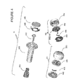
- FIG. 4 illustrates an exploded view “A” of the main mount components along with the positive battery contact and battery, while view “B 1 ” shows a top oriented view of the insulator, negative battery contact, electronics package, here a printed circuit board or PCB and cap, while view “B 2 ” shows a bottom oriented view of the same components shown in view “B 1 ”.
- FIG. 4A illustrates an exploded view “A” of the main mount components of a second embodiment of the invention along with the positive and negative battery contact and battery, while view “B” shows a bottom oriented view of the insulator, positive and negative battery contact, electronics package, here a printed circuit board or PCB and cap.
- FIG. 4B illustrates a perspective view of the shaft enclosure and insulator of a second embodiment of the invention along with the positive and negative battery contact and battery.
- FIG. 4C illustrates a perspective view of the insulator along with the positive and negative battery contact and battery.
- FIG. 4D illustrates a perspective close-up view of the positive battery contact.
- FIG. 4E illustrates a top view of an embodiment of the insulator that is configured to house a battery along with specific exemplary dimensions.
- FIG. 4F illustrates a first side of the embodiment of the insulator of FIG. 4E .
- FIG. 4G illustrates a second side of the embodiment of the insulator of FIG. 4E .
- FIG. 4H illustrates a cross section view “A” of FIG. 4F .
- FIG. 4I illustrates a bottom view of the embodiment of the insulator of FIG. 4E .
- FIG. 5 illustrates a close up perspective view of the PCB and associated positive and negative contacts that are configured to make an electrical connection with the positive battery contact and the negative battery contact respectively.
- FIG. 5A illustrates a second embodiment of the positive battery contact located in the shaft enclosure.
- FIG. 6 illustrates a close up perspective view of the cap with PCB and negative battery contact showing along with a coupling element, here four coupling points, and alignment element.
- FIG. 6A illustrates a second embodiment of the negative batter contact having faceted surfaces as shown from the bottom side of the insulator.
- FIG. 6B illustrates the embodiment of FIG. 6A as shown from the top side of the insulator.
- FIG. 7 illustrates a close up perspective view of the cap and alignment element.
- FIG. 8 illustrates a cutaway view of a second embodiment of the electronics package in longitudinal form along with a second embodiment of a coupling element.
- FIG. 9 illustrates an embodiment of a wireless antenna, for example a BLUETOOTH® antenna, configured to mount within the cap.
- a wireless antenna for example a BLUETOOTH® antenna
- FIG. 9A illustrates an embodiment of the cap having two antennas, a wireless antenna, for example a BLUETOOTH® antenna and a GPS antenna.
- a wireless antenna for example a BLUETOOTH® antenna and a GPS antenna.
- FIG. 1 illustrates an embodiment of the invention 100 alone in perspective view and as mounted in a shaft of a piece of movement equipment, here golf club shaft 110 as shown in cutaway view.
- Embodiments enable a mount for a new golf club or that can be retrofitted in an existing golf club.
- the mount may be located in the handle portion of the shaft of the golf club, or for example within a grip that is to be attached to the golf club shaft, and is configured to hold electronics and/or a visual marker.
- FIG. 2 illustrates an embodiment of the invention broken into an exploded view of the main components along with the golf club shaft handle and blow up views of the major components in transparent shading.
- One or more embodiments of the mount include shaft enclosure 220 and expander 210 that may be coupled with an attachment mechanism, for example a screw aligned along an axis parallel to the axis of the golf club shaft.
- the shaft enclosure and expander are situated within the handle portion of a golf club, i.e., golf club shaft 110 .
- the screw is then rotated to move the shaft enclosure towards the expander, which thus forces legs of the shaft enclosure in a direction orthogonal to the axis of the golf club shaft.
- the force of the shaft enclosure against the inner wall of the golf club shaft thus couples the shaft enclosure to the golf club shaft based on the coefficient of static friction therebetween.
- Any other mechanism of coupling the shaft enclosure to a golf club in a non-permanent manner is in keeping with the spirit of the invention.
- either the electronics package or a weight element that may for example weigh the same as the electronics is coupled with the shaft enclosure.
- Cap 230 is coupled with the shaft enclosure in either case, which provides a cover for the weight element or electronics package and which may include a visual marker and/or logo on the cap.
- One or more embodiments of the electronics package are removable to comply with any sporting rules that do not allow instrumented sporting equipment for example. Any other method or structure that enables a non-permanent mount of the apparatus that requires no modification of the golf club shaft is in keeping with the spirit of the invention.
- an identification element or ID sticker for example an RFID tag may be mounted within the shaft enclosure, cap, or any other portion of the apparatus, for shot count or club identification functionality.
- the identification element may also be implemented integral to, or coupled with the PCB in any manner as desired.
- a positive battery contact, printed circuit board or PCB, an insulator or insulative spacer, with negative electrical contact and battery may be installed between the shaft enclosure and cap.
- a wireless antenna and/or GPS antenna may be coupled with the cap or alternatively may be implemented integral to the PCB as desired. Also see FIGS. 3A-C , 4 , 4 A-D and 9 for more detailed views.
- FIG. 3A illustrates a detailed cutaway view of the main components of an embodiment of the invention, specifically expander 210 , shaft enclosure 220 and cap 230 .
- FIG. 3B illustrates a detailed cutaway view showing negative battery contact 450 , also shown in full in exploded view in FIG. 4 .
- FIG. 3C illustrates a detailed cutaway view showing positive battery contact 420 , also shown in full in exploded view in FIG. 4 .
- Optional O-ring indentation 310 on shaft enclosure 220 provides a potential well for O-ring 320 to be located. Different size O-rings may be utilized to provide a secure fit on the end of shaft enclosure 220 on the end near cap 230 .
- FIG. 4 illustrates an exploded view “A” of the main mount components, namely expander 210 , shaft enclosure 220 along with screw 410 , positive battery contact 420 and battery 430 , while view “B 1 ” shows a top oriented view of the insulator 440 , negative battery contact 450 , electronics package 460 , here a printed circuit board or PCB and cap 230 , while view “B 2 ” shows a bottom oriented view of the same components shown in view “B 1 ”.
- the left portion of shaft enclosure 220 shows extensions or “legs” that allow for the shaft enclosure to radially expand when expander 210 is pulled along the axis shown by screw 410 , when screw 410 is rotated.
- expander 210 may include a protrusion (shown on the left side of the expander) that aligns in a slot formed by two of the shaft enclosure's legs. In this manner, expander 210 is pulled along the axis of the screw without rotating along that axis.
- Electronics package 460 for example may include active motion capture electronics that are battery powered, passive or active shot count components, for example a passive or active RFID tag, which for example may be coupled with electronics package 460 or for example coupled with insulator 440 .
- a GPS antenna may also be coupled with electronics package 460 or cap 230 (see FIG. 9A ).
- Embodiments of the electronics may include motion capture accelerometers and/or gyroscopes and/or an inertial measurement unit along with wireless transmitter/receiver or transceiver components.
- the RFID tag enables golf shots for each club associated with a golfer to be counted.
- the RFID tag may be coupled with any component shown as RFID tags are tiny, for example cap 230 or shaft enclosure 220 or electronics package 460 , or any other element. Golf shots may optionally be counted via an identifier associated with motion capture electronics on the golf club in conjunction with a mobile computer, for example an IPHONE® equipped with an RFID reader that concentrates the processing for golf shot counting on the mobile computer instead of on each golf club.
- the visual marker may be mounted on cap 230 , shown as a circle with dots in view B 1 may be utilized with visual motion capture cameras.
- a golf club number may also be displayed on in a display area of the cap to indicate which club number is associated with the golf club, which is shown as a small circle with a number in it in view B 1 .
- Embodiments of the visual marker may be passive or active, meaning that they may either have a visual portion that is visually trackable or may include a light emitting element such as a light emitting diode (LED) that allows for image tracking in low light conditions respectively. This for example may be implemented with a graphical symbol or colored marker at the cap of the mount on the shaft at the end of the handle for example.
- Motion analysis may be performed externally, for example using a camera and computer system based on the visual marker in any captured images.
- the visual data may also be utilized in motion analysis in combination with any wireless data from electronics package 460 .
- FIG. 4A illustrates an exploded view “A” of the main mount components of a second embodiment of the invention, namely expander 210 a, with ribs slightly offset with respect to expander 210 of FIG. 4 .
- FIG. 4A also shows a second embodiment of shaft enclosure 220 a having coupling elements that enable second embodiment of insulator 440 a to securely couple to shaft enclosure 220 a without falling out if the mount is turned upside down for example.
- insulator 440 a holds battery 430 inside while providing access to the battery so that positive battery contact 420 a and negative battery contact 450 a can make electrical contact with battery 430 .
- Weight element 490 can be any shape so long as weight element 490 fits within, or couples in any direct or indirect manner with shaft enclosure 220 or 220 a and cap 230 for example. Weight element 490 can be made to weigh as near as desired to the weight of the components that it replaces, for example to comply with any sporting rules that do not allow instrumented sporting equipment, e.g., during competition. Weight element 490 can also be utilized with the embodiment shown in FIG. 4 as one skilled in the art will appreciate.
- FIG. 4B illustrates a perspective view of shaft enclosure 220 a and insulator 440 a of the second embodiment of the invention of FIG. 4A along with the positive and negative battery contact 420 a and 450 a respectively (situated above holes in insulator 440 a ) along with battery 430 that is internally held within insulator 440 a.
- Insulator 440 a includes for example snap components, e.g., coupling elements 441 that couple with coupling elements 221 of shaft enclosure 220 a so that insulator 440 a and hence battery 430 do not fall out when the cap is removed.
- tab 442 may be engaged with for example a finger, screw driver or other implement to disengage coupling elements 441 from coupling elements 221 .
- Alignment component 443 enables rotational alignment of the insulator with the shaft enclosure.
- FIG. 4C illustrates a perspective view of the insulator along with the positive and negative battery contact 420 a and 450 a respectively, and battery 430 .
- Coupling elements 441 are shown on the top and bottom in the written page, however any type of coupling element may be utilized in keeping with the spirit of the invention as desired.
- FIG. 4D illustrates a perspective close-up view of positive battery contact 420 a.
- the positive and negative battery contacts may utilize the same structure. Any type of positive and negative battery contacts may be utilized so long as they maintain electric connection between the battery and electronics package.
- FIG. 4E illustrates a top view of an embodiment of insulator 440 a that is configured to house a battery along with specific exemplary dimensions.
- tab 442 may be engaged with for example a finger, screw driver or other implement to disengage coupling elements 441 from the coupling elements shown for example in FIG. 4B .
- the numbers represent millimeters, and angle tolerances are within 2 degrees.
- this embodiment of insulator 440 a is configured to house a 6.4 mm battery.
- insulator 440 a may be constructed to be compliant with EU Directive 2002/95/EC (RoHS) and EU Directive 2002/96/EC (WEEE). Embodiments may alternatively be constructed to be compliant with any other electrical or manufacturing standards as desired.
- FIG. 4F illustrates a first side of the embodiment of the insulator of FIG. 4E . See also FIG. 4H for the cross section view.
- FIG. 4G illustrates a second side of the embodiment of the insulator of FIG. 4E .
- FIG. 4H illustrates a cross section view “A” of FIG. 4F .
- FIG. 4I illustrates a bottom view of the embodiment of the insulator of FIG. 4E .
- FIG. 5 illustrates a close up perspective view of the electronics package 460 or PCB and associated positive contact 510 and negative contact 520 that are configured to make an electrical connection with the positive battery contact 420 and the negative battery contact 450 respectively. See also FIG. 4 for an exploded view of the relative positioning of the components shown in this figure.
- FIG. 5A illustrates a second embodiment of positive battery contact 420 b located in the shaft enclosure.
- This embodiment is symmetrical in that there are two opposing sets of upward projections from the base plane that contacts shaft enclosure 220 .
- One of the opposing sets of upward projections of positive battery contact 420 b are slightly wider and are positioned within areas on shaft enclosure 220 to allow for radially aligning positive battery contact 420 b with respect to shaft enclosure 220 .
- FIG. 6 illustrates a close up perspective view of cap 230 with electronics package 460 or PCB and negative battery contact 450 coupled with insulator 440 showing along with a coupling element, here four coupling points 610 (with only the top two shown with reference number 610 with the inside portions visible, while the opposing two have only the initial slot openings in the cap visible), and alignment element 620 .
- a coupling element here four coupling points 610 (with only the top two shown with reference number 610 with the inside portions visible, while the opposing two have only the initial slot openings in the cap visible), and alignment element 620 .
- FIG. 6A illustrates a second embodiment of the negative battery contact 450 b having faceted surfaces as shown from the bottom side of insulator 440 .
- FIG. 6B illustrates the embodiment of FIG. 6A as shown from the top side of the insulator.
- the right portion of negative battery contact 450 b as shown may be folded over to engage insulator 440 while the opposing end of negative battery contact 450 b may freely travel in a slot provided in insulator 440 .
- the slot allows for the negative battery contact 450 b to flatten, and hence travel in the slot, based on the force generated by placing the battery against negative battery contact 450 b.
- FIG. 7 illustrates a close up perspective view of the cap and alignment element.
- Alignment element 620 allows for the angular alignment of insulator 440 , and electronics package 460 that have indents on their sides to engage the alignment element 620 . (See FIG. 4 ).
- positive battery contact 420 and negative electrical contact 450 are also aligned rotationally since they couple to respective components non-rotationally, for example.
- FIG. 8 illustrates a cutaway view of a second embodiment of electronics package 460 a in longitudinal form along with a second embodiment of a coupling element.
- Any other orientation of electronics is in keeping with the spirit of the invention so long as the mount is configured to hold the desired electronics package.
- Embodiments of the invention do not require modifying the golf club, for example to include threads within the shaft.
- Embodiments of the invention also can be flush mounted with the normal end of a golf club shaft or have any desired low profile extension from a non-instrumented club.
- Embodiments of the invention generally utilize a mount that is separate from the electronics so that the electronics package can be easily removed and replaced, or so that the battery can be easily removed and replaced, for example without any tools.
- a different coupling mechanism is used versus coupling points 610 , namely threads 810 that engage shaft enclosure 220 , which in this embodiment has corresponding threads.
- FIG. 9 illustrates an embodiment of wireless antenna 910 , configured to mount within cap 230 as shown in the right portion of the figure.
- the wireless antenna may be coupled with the electronics package 460 or may include any conductive element in any shape that can radiate electromagnetic energy.
- FIG. 9A illustrates an embodiment of the cap having two antennas, a wireless antenna, for example a BLUETOOTH® antenna and a GPS antenna 920 .
- the GPS antenna is optional and may be mounted in cap 230 as wireless antenna 910 is, or may be implemented in a different form factor or coupled with the PCB in any direct or indirect manner as one skilled in the art will appreciate.
Abstract
Description
- This application is a continuation-in-part of U.S. Utility patent application Ser. No. 13/048,850 filed 15 Mar. 2011, which is a continuation-in-part of U.S. Utility patent application Ser. No. 12/901,806 filed 11 Oct. 2010, which is a continuation-in-part of U.S. Utility patent application Ser. No. 12/868,882 filed 26 Aug. 2010, the specifications of which are hereby incorporated herein by reference.
- 1. Field of the Invention
- One or more embodiments setting forth the ideas described throughout this disclosure pertain to the field of mounts as utilized in sporting equipment for electronics and visual markers. More particularly, but not by way of limitation, one or more aspects of the disclosure enable a motion capture element mount.
- 2. Description of the Related Art
- Known systems for mounting electronics on sporting equipment include mounts in the shafts of fishing poles, and golf clubs for example. Existing mounts have the following limitations:
- Existing mounts for sporting equipment electronics require alteration of an existing piece of sporting equipment before attaching the mount and hence electronics. For example, known mounts require modification of a golf club shaft to include threads.
- Some mounts extend longitudinally away from the normal ending point of the shaft for a distance that is far enough to interfere with or provide a confusing point at which to grasp the club.
- Other mounts combine the electronics on the mount itself in a monolithic package that does not allow for the weight of the club to remain constant with or without electronics installed. For example, in sports with rules against instrumented sporting equipment, the weight of an instrumented piece of sporting equipment differs from the weight of the same non-instrumented piece of sporting equipment that complies with competition rules.
- There are no known systems that include electronics within the shaft of a piece of sporting equipment that are also utilized to provide a visual marker for motion capture. Traditionally, mounts have been used for electronics or visual markers, but not both.
- For at least the limitations described above there is a need for a motion capture element mount.
- Embodiments of the invention enable a motion capture element mount for a piece of sporting, exercise or medical rehabilitation equipment, for example a golf club, tennis racquet, weight training bar, or any other equipment capable of movement by a human. In addition, embodiments enable existing equipment that was not manufactured originally with a mount for electronics to be retrofitted with a motion capture element mount. The apparatus may be located within a shaft or grip in the handle portion of the equipment for example. The mount is configured to hold electronics and/or a visual marker. Embodiments of the invention do not require modifying the equipment, for example the golf club, to include threads within the shaft. The apparatus may be flush mounted with the normal end of the equipment or have any desired length of extension from the end of the equipment. The mount also allows for the battery to be easily removed and replaced, for example without any tools. Although the remainder of this disclosure refers to an exemplary piece of equipment such as a golf club, one skilled in the art will recognize that embodiments of the invention may be utilized in any type of equipment capable of coupling with the apparatus.
- One or more embodiments of the mount include a shaft enclosure and expander that may be coupled with an attachment element, for example a screw that is aligned along an axis parallel to the axis of the golf club shaft. The shaft enclosure and expander are situated within the handle portion of a golf club and engage in inner portion of the golf club shaft or grip for example. In one or more embodiments, the screw is then rotated to move the shaft enclosure and expander together, which thus forces legs of the shaft enclosure in a direction orthogonal to the axis of the golf club shaft. The force of the shaft enclosure against the inner wall of the golf club shaft thus couples the shaft enclosure to the golf club shaft non-permanently, for example based on the coefficient of static friction therebetween. After the shaft enclosure and expander are brought close enough together via the attachment element to securely couple the mount to the golf club shaft or inside portion of a grip that is coupled to the golf club shaft, then either the electronics package or a weight element is coupled with the shaft enclosure. Embodiments of the weight element require no modification of the equipment. A cap is coupled with the shaft enclosure in either case, which provides a cover for the weight element or electronics package and which may include a visual marker and/or logo on the cap. Any other method or structure that enables a non-permanent mount of the apparatus that requires no modification of the golf club shaft is in keeping with the spirit of the invention.
- If the electronics package is installed, then generally a positive battery contact, printed circuit board (PCB), an insulator or insulative spacer, with negative electrical contact and battery may be installed between the shaft enclosure and cap. The electronics that may be coupled with the PCB for example may include active motion capture electronics that are battery powered, passive or active shot count components, for example a passive or active radio frequency identification (RFID) tag. Embodiments of the electronics may include motion capture accelerometers and/or gyroscopes and/or an inertial measurement unit along with wireless transmitter/receiver or transceiver components. The RFID tag enables golf shots for each club associated with a golfer to be counted. Golf shots may optionally be counted via an identifier associated with motion capture electronics on the golf club in conjunction with a mobile computer, for example an IPHONE® equipped with an RFID reader that concentrates the processing for golf shot counting on the mobile computer instead of on each golf club. Optionally a wireless antenna may be coupled with the cap or alternatively may be implemented integral to the PCB as desired. One or more embodiments of the invention may also include a Global Positioning System (GPS) antenna. The GPS antenna may be mounted on the printed circuit board or may be located separate from the printed circuit board. One or more embodiments of the invention may also directly or indirectly communicate with any other sensors coupled with the club including motion analysis capture elements, strain gauges or any other type of sensor coupled for example with the golf club head. One or more embodiments of the invention may also utilize a battery coupling that attaches the battery to the shaft enclosure so that when the cap is removed, the battery does not fall out, unless intended. Embodiments may also utilized spring based electrical contacts to prevent loss of electrical conductivity under high acceleration.
- As previously stated, one or more embodiments may include a weight element that is interchangeable with the electronic package in the mount. The electronics package may be removed for example to comply with any sporting rules that do not allow instrumented sporting equipment. For example, USGA Rule 14-3 on Artificial Devices prohibits any “unusual device”, for example under 14-3(b) “For the purpose of gauging or measuring distance”. Any embodiment of the electronics package including a GPS receiver may thus be removed prior to match play for example and replaced with a weight element to minimize the weight difference. For example, the weight element may for example weigh close to or the same as the electronics to minimize overall instrumented versus non-instrumented weight differences of the golf club. In addition, a manufacture may provide the mount on each club with a small weight for example, that is removed when the golfer decides to upgrade the club to include active instrumented electronics or passive shot count elements that weigh the same amount. The net effect on the club dynamics for swing then is negligible. In one embodiment, the plastic portion of the mount weighs 5.7 grams and the battery weighs 3 grams while the screw weighs 1.9 grams. Thus the mounting components have minimal weight and by selecting a weight element of the same weight of the electronics package, or elements within the shaft enclosure and cap that are replaced by the weight element, the golfer feels no change in club weight when upgrading to an instrumented club.
- The visual marker may be mounted on the cap for use with visual motion capture cameras. A golf club number may also be displayed on in a display area of the cap to indicate which club number is associated with the golf club. Embodiments of the visual marker may be passive or active, meaning that they may either have a visual portion that is visually trackable or may include a light emitting element such as a light emitting diode (LED) that allows for image tracking in low light conditions respectively. This for example may be implemented with a graphical symbol or colored marker at the cap of the mount on the shaft at the end of the handle for example. Motion analysis may be performed externally, for example using a camera and computer system based on the visual marker in any captured images. The visual data may also be utilized in motion analysis in combination with any wireless data from any installed electronics package.
- The above and other aspects, features and advantages of the ideas conveyed through this disclosure will be more apparent from the following more particular description thereof, presented in conjunction with the following drawings wherein:
-
FIG. 1 illustrates an embodiment of the invention alone in perspective view and as mounted in a golf club shaft as shown in cutaway view. -
FIG. 2 illustrates an embodiment of the invention broken into an exploded view of the main components along with the golf club shaft handle and blow up views of the major components in transparent shading. -
FIG. 3A illustrates a detailed cutaway view of the main components of an embodiment of the invention. -
FIG. 3B illustrates a detailed cutaway view showing the negative battery contact, also shown in full in exploded view inFIG. 4 . -
FIG. 3C illustrates a detailed cutaway view showing the positive battery contact, also shown in full in exploded view inFIG. 4 . -
FIG. 4 illustrates an exploded view “A” of the main mount components along with the positive battery contact and battery, while view “B1” shows a top oriented view of the insulator, negative battery contact, electronics package, here a printed circuit board or PCB and cap, while view “B2” shows a bottom oriented view of the same components shown in view “B1”. -
FIG. 4A illustrates an exploded view “A” of the main mount components of a second embodiment of the invention along with the positive and negative battery contact and battery, while view “B” shows a bottom oriented view of the insulator, positive and negative battery contact, electronics package, here a printed circuit board or PCB and cap. -
FIG. 4B illustrates a perspective view of the shaft enclosure and insulator of a second embodiment of the invention along with the positive and negative battery contact and battery. -
FIG. 4C illustrates a perspective view of the insulator along with the positive and negative battery contact and battery. -
FIG. 4D illustrates a perspective close-up view of the positive battery contact. -
FIG. 4E illustrates a top view of an embodiment of the insulator that is configured to house a battery along with specific exemplary dimensions. -
FIG. 4F illustrates a first side of the embodiment of the insulator ofFIG. 4E . -
FIG. 4G illustrates a second side of the embodiment of the insulator ofFIG. 4E . -
FIG. 4H illustrates a cross section view “A” ofFIG. 4F . -
FIG. 4I illustrates a bottom view of the embodiment of the insulator ofFIG. 4E . -
FIG. 5 illustrates a close up perspective view of the PCB and associated positive and negative contacts that are configured to make an electrical connection with the positive battery contact and the negative battery contact respectively. -
FIG. 5A illustrates a second embodiment of the positive battery contact located in the shaft enclosure. -
FIG. 6 illustrates a close up perspective view of the cap with PCB and negative battery contact showing along with a coupling element, here four coupling points, and alignment element. -
FIG. 6A illustrates a second embodiment of the negative batter contact having faceted surfaces as shown from the bottom side of the insulator. -
FIG. 6B illustrates the embodiment ofFIG. 6A as shown from the top side of the insulator. -
FIG. 7 illustrates a close up perspective view of the cap and alignment element. -
FIG. 8 illustrates a cutaway view of a second embodiment of the electronics package in longitudinal form along with a second embodiment of a coupling element. -
FIG. 9 illustrates an embodiment of a wireless antenna, for example a BLUETOOTH® antenna, configured to mount within the cap. -
FIG. 9A illustrates an embodiment of the cap having two antennas, a wireless antenna, for example a BLUETOOTH® antenna and a GPS antenna. - A motion capture element mount will now be described. In the following exemplary description numerous specific details are set forth in order to provide a more thorough understanding of the ideas described throughout this specification. It will be apparent, however, to an artisan of ordinary skill that embodiments of ideas described herein may be practiced without incorporating all aspects of the specific details described herein. In other instances, specific aspects well known to those of ordinary skill in the art have not been described in detail so as not to obscure the disclosure. Readers should note that although examples of the innovative concepts are set forth throughout this disclosure, the claims, and the full scope of any equivalents, are what define the invention. Although this disclosure refers to an exemplary piece of equipment such as a golf club, one skilled in the art will recognize that embodiments of the invention may be utilized in any equipment capable of coupling with the apparatus. This includes any piece of sporting, exercise or medical rehabilitation equipment, for example a golf club, tennis racquet, weight training bar, or any other equipment capable of movement by a human.
-
FIG. 1 illustrates an embodiment of theinvention 100 alone in perspective view and as mounted in a shaft of a piece of movement equipment, heregolf club shaft 110 as shown in cutaway view. Embodiments enable a mount for a new golf club or that can be retrofitted in an existing golf club. The mount may be located in the handle portion of the shaft of the golf club, or for example within a grip that is to be attached to the golf club shaft, and is configured to hold electronics and/or a visual marker. -
FIG. 2 illustrates an embodiment of the invention broken into an exploded view of the main components along with the golf club shaft handle and blow up views of the major components in transparent shading. One or more embodiments of the mount includeshaft enclosure 220 andexpander 210 that may be coupled with an attachment mechanism, for example a screw aligned along an axis parallel to the axis of the golf club shaft. The shaft enclosure and expander are situated within the handle portion of a golf club, i.e.,golf club shaft 110. In one or more embodiments, the screw is then rotated to move the shaft enclosure towards the expander, which thus forces legs of the shaft enclosure in a direction orthogonal to the axis of the golf club shaft. The force of the shaft enclosure against the inner wall of the golf club shaft thus couples the shaft enclosure to the golf club shaft based on the coefficient of static friction therebetween. Any other mechanism of coupling the shaft enclosure to a golf club in a non-permanent manner is in keeping with the spirit of the invention. After the shaft enclosure and expander are brought close enough together via the screw to securely couple the mount to the golf club shaft, then either the electronics package or a weight element that may for example weigh the same as the electronics, is coupled with the shaft enclosure.Cap 230 is coupled with the shaft enclosure in either case, which provides a cover for the weight element or electronics package and which may include a visual marker and/or logo on the cap. One or more embodiments of the electronics package are removable to comply with any sporting rules that do not allow instrumented sporting equipment for example. Any other method or structure that enables a non-permanent mount of the apparatus that requires no modification of the golf club shaft is in keeping with the spirit of the invention. - Optionally, an identification element or ID sticker, for example an RFID tag may be mounted within the shaft enclosure, cap, or any other portion of the apparatus, for shot count or club identification functionality. The identification element may also be implemented integral to, or coupled with the PCB in any manner as desired.
- If the electronics package is installed, then generally a positive battery contact, printed circuit board or PCB, an insulator or insulative spacer, with negative electrical contact and battery may be installed between the shaft enclosure and cap. Optionally, a wireless antenna and/or GPS antenna may be coupled with the cap or alternatively may be implemented integral to the PCB as desired. Also see
FIGS. 3A-C , 4, 4A-D and 9 for more detailed views. -
FIG. 3A illustrates a detailed cutaway view of the main components of an embodiment of the invention, specifically expander 210,shaft enclosure 220 andcap 230.FIG. 3B illustrates a detailed cutaway view showingnegative battery contact 450, also shown in full in exploded view inFIG. 4 .FIG. 3C illustrates a detailed cutaway view showingpositive battery contact 420, also shown in full in exploded view inFIG. 4 . Optional O-ring indentation 310 onshaft enclosure 220 provides a potential well for O-ring 320 to be located. Different size O-rings may be utilized to provide a secure fit on the end ofshaft enclosure 220 on the end nearcap 230. -
FIG. 4 illustrates an exploded view “A” of the main mount components, namelyexpander 210,shaft enclosure 220 along withscrew 410,positive battery contact 420 andbattery 430, while view “B1” shows a top oriented view of theinsulator 440,negative battery contact 450,electronics package 460, here a printed circuit board or PCB andcap 230, while view “B2” shows a bottom oriented view of the same components shown in view “B1”. The left portion ofshaft enclosure 220 shows extensions or “legs” that allow for the shaft enclosure to radially expand whenexpander 210 is pulled along the axis shown byscrew 410, whenscrew 410 is rotated. To keep expander 210 from simply rotating whenscrew 410 is rotated,expander 210 may include a protrusion (shown on the left side of the expander) that aligns in a slot formed by two of the shaft enclosure's legs. In this manner,expander 210 is pulled along the axis of the screw without rotating along that axis.Electronics package 460 for example may include active motion capture electronics that are battery powered, passive or active shot count components, for example a passive or active RFID tag, which for example may be coupled withelectronics package 460 or for example coupled withinsulator 440. In addition, a GPS antenna may also be coupled withelectronics package 460 or cap 230 (seeFIG. 9A ). Embodiments of the electronics may include motion capture accelerometers and/or gyroscopes and/or an inertial measurement unit along with wireless transmitter/receiver or transceiver components. The RFID tag enables golf shots for each club associated with a golfer to be counted. The RFID tag may be coupled with any component shown as RFID tags are tiny, forexample cap 230 orshaft enclosure 220 orelectronics package 460, or any other element. Golf shots may optionally be counted via an identifier associated with motion capture electronics on the golf club in conjunction with a mobile computer, for example an IPHONE® equipped with an RFID reader that concentrates the processing for golf shot counting on the mobile computer instead of on each golf club. - The visual marker may be mounted on
cap 230, shown as a circle with dots in view B1 may be utilized with visual motion capture cameras. A golf club number may also be displayed on in a display area of the cap to indicate which club number is associated with the golf club, which is shown as a small circle with a number in it in view B1. Embodiments of the visual marker may be passive or active, meaning that they may either have a visual portion that is visually trackable or may include a light emitting element such as a light emitting diode (LED) that allows for image tracking in low light conditions respectively. This for example may be implemented with a graphical symbol or colored marker at the cap of the mount on the shaft at the end of the handle for example. Motion analysis may be performed externally, for example using a camera and computer system based on the visual marker in any captured images. The visual data may also be utilized in motion analysis in combination with any wireless data fromelectronics package 460. -
FIG. 4A illustrates an exploded view “A” of the main mount components of a second embodiment of the invention, namely expander 210 a, with ribs slightly offset with respect toexpander 210 ofFIG. 4 . In addition,FIG. 4A also shows a second embodiment ofshaft enclosure 220 a having coupling elements that enable second embodiment ofinsulator 440 a to securely couple toshaft enclosure 220 a without falling out if the mount is turned upside down for example. In this embodiment,insulator 440 a holdsbattery 430 inside while providing access to the battery so thatpositive battery contact 420 a andnegative battery contact 450 a can make electrical contact withbattery 430. View “B” shows a bottom-oriented view of the insulator, positive and negative battery contact, electronics package, here a printed circuit board or PCB and cap.Weight element 490 can be any shape so long asweight element 490 fits within, or couples in any direct or indirect manner withshaft enclosure cap 230 for example.Weight element 490 can be made to weigh as near as desired to the weight of the components that it replaces, for example to comply with any sporting rules that do not allow instrumented sporting equipment, e.g., during competition.Weight element 490 can also be utilized with the embodiment shown inFIG. 4 as one skilled in the art will appreciate. -
FIG. 4B illustrates a perspective view ofshaft enclosure 220 a andinsulator 440 a of the second embodiment of the invention ofFIG. 4A along with the positive andnegative battery contact insulator 440 a) along withbattery 430 that is internally held withininsulator 440 a.Insulator 440 a includes for example snap components, e.g., couplingelements 441 that couple withcoupling elements 221 ofshaft enclosure 220 a so thatinsulator 440 a and hencebattery 430 do not fall out when the cap is removed. To removeinsulator 440 a and hencebattery 430,tab 442 may be engaged with for example a finger, screw driver or other implement to disengagecoupling elements 441 from couplingelements 221.Alignment component 443 enables rotational alignment of the insulator with the shaft enclosure. -
FIG. 4C illustrates a perspective view of the insulator along with the positive andnegative battery contact battery 430. Couplingelements 441 are shown on the top and bottom in the written page, however any type of coupling element may be utilized in keeping with the spirit of the invention as desired. -
FIG. 4D illustrates a perspective close-up view ofpositive battery contact 420 a. In one or more embodiments of the invention, the positive and negative battery contacts may utilize the same structure. Any type of positive and negative battery contacts may be utilized so long as they maintain electric connection between the battery and electronics package. -
FIG. 4E illustrates a top view of an embodiment ofinsulator 440 a that is configured to house a battery along with specific exemplary dimensions. To removeinsulator 440 a and hence the battery withininsulator 440 a,tab 442 may be engaged with for example a finger, screw driver or other implement to disengagecoupling elements 441 from the coupling elements shown for example inFIG. 4B . In this figure, the numbers represent millimeters, and angle tolerances are within 2 degrees. As shown, this embodiment ofinsulator 440 a is configured to house a 6.4 mm battery. Although not required for distribution in some countries, one or more embodiments ofinsulator 440 a may be constructed to be compliant with EU Directive 2002/95/EC (RoHS) and EU Directive 2002/96/EC (WEEE). Embodiments may alternatively be constructed to be compliant with any other electrical or manufacturing standards as desired. -
FIG. 4F illustrates a first side of the embodiment of the insulator ofFIG. 4E . See alsoFIG. 4H for the cross section view.FIG. 4G illustrates a second side of the embodiment of the insulator ofFIG. 4E .FIG. 4H illustrates a cross section view “A” ofFIG. 4F .FIG. 4I illustrates a bottom view of the embodiment of the insulator ofFIG. 4E . -
FIG. 5 illustrates a close up perspective view of theelectronics package 460 or PCB and associatedpositive contact 510 andnegative contact 520 that are configured to make an electrical connection with thepositive battery contact 420 and thenegative battery contact 450 respectively. See alsoFIG. 4 for an exploded view of the relative positioning of the components shown in this figure. -
FIG. 5A illustrates a second embodiment ofpositive battery contact 420 b located in the shaft enclosure. This embodiment is symmetrical in that there are two opposing sets of upward projections from the base plane thatcontacts shaft enclosure 220. One of the opposing sets of upward projections ofpositive battery contact 420 b are slightly wider and are positioned within areas onshaft enclosure 220 to allow for radially aligningpositive battery contact 420 b with respect toshaft enclosure 220. -
FIG. 6 illustrates a close up perspective view ofcap 230 withelectronics package 460 or PCB andnegative battery contact 450 coupled withinsulator 440 showing along with a coupling element, here four coupling points 610 (with only the top two shown withreference number 610 with the inside portions visible, while the opposing two have only the initial slot openings in the cap visible), andalignment element 620. -
FIG. 6A illustrates a second embodiment of thenegative battery contact 450 b having faceted surfaces as shown from the bottom side ofinsulator 440.FIG. 6B illustrates the embodiment ofFIG. 6A as shown from the top side of the insulator. The right portion ofnegative battery contact 450 b as shown may be folded over to engageinsulator 440 while the opposing end ofnegative battery contact 450 b may freely travel in a slot provided ininsulator 440. The slot allows for thenegative battery contact 450 b to flatten, and hence travel in the slot, based on the force generated by placing the battery againstnegative battery contact 450 b. -
FIG. 7 illustrates a close up perspective view of the cap and alignment element.Alignment element 620 allows for the angular alignment ofinsulator 440, andelectronics package 460 that have indents on their sides to engage thealignment element 620. (SeeFIG. 4 ). By aligninginsulator 440 andelectronics package 460 withcap 230,positive battery contact 420 and negativeelectrical contact 450 are also aligned rotationally since they couple to respective components non-rotationally, for example. -
FIG. 8 illustrates a cutaway view of a second embodiment ofelectronics package 460 a in longitudinal form along with a second embodiment of a coupling element. Any other orientation of electronics is in keeping with the spirit of the invention so long as the mount is configured to hold the desired electronics package. Embodiments of the invention do not require modifying the golf club, for example to include threads within the shaft. Embodiments of the invention also can be flush mounted with the normal end of a golf club shaft or have any desired low profile extension from a non-instrumented club. Embodiments of the invention generally utilize a mount that is separate from the electronics so that the electronics package can be easily removed and replaced, or so that the battery can be easily removed and replaced, for example without any tools. As shown in this embodiment, a different coupling mechanism is used versus coupling points 610, namelythreads 810 that engageshaft enclosure 220, which in this embodiment has corresponding threads. -
FIG. 9 illustrates an embodiment ofwireless antenna 910, configured to mount withincap 230 as shown in the right portion of the figure. Alternatively, the wireless antenna may be coupled with theelectronics package 460 or may include any conductive element in any shape that can radiate electromagnetic energy. -
FIG. 9A illustrates an embodiment of the cap having two antennas, a wireless antenna, for example a BLUETOOTH® antenna and aGPS antenna 920. The GPS antenna is optional and may be mounted incap 230 aswireless antenna 910 is, or may be implemented in a different form factor or coupled with the PCB in any direct or indirect manner as one skilled in the art will appreciate. - While the ideas herein disclosed has been described by means of specific embodiments and applications thereof, numerous modifications and variations could be made thereto by those skilled in the art without departing from the scope of the invention set forth in the claims.
Claims (20)
Priority Applications (61)
| Application Number | Priority Date | Filing Date | Title |
|---|---|---|---|
| US13/191,309 US9033810B2 (en) | 2010-08-26 | 2011-07-26 | Motion capture element mount |
| CA2812734A CA2812734C (en) | 2010-08-26 | 2011-08-26 | Portable wireless mobile device motion capture and analysis system and method |
| PCT/US2011/049461 WO2012027726A2 (en) | 2010-08-26 | 2011-08-26 | Portable wireless mobile device motion capture and analysis system and method |
| AU2011293130A AU2011293130B2 (en) | 2010-08-26 | 2011-08-26 | Portable wireless mobile device motion capture and analysis system and method |
| EP11820763.8A EP2609568B8 (en) | 2010-08-26 | 2011-08-26 | Portable wireless mobile device motion capture and analysis system and method |
| US13/219,525 US8941723B2 (en) | 2010-08-26 | 2011-08-26 | Portable wireless mobile device motion capture and analysis system and method |
| US13/267,784 US9604142B2 (en) | 2010-08-26 | 2011-10-06 | Portable wireless mobile device motion capture data mining system and method |
| EP11833159.4A EP2628101B1 (en) | 2010-10-11 | 2011-10-06 | Portable wireless mobile device motion capture data mining system and method |
| CA2817875A CA2817875C (en) | 2010-10-11 | 2011-10-06 | Portable wireless mobile device motion capture data mining system and method |
| PCT/US2011/055173 WO2012051054A1 (en) | 2010-10-11 | 2011-10-06 | Portable wireless mobile device motion capture data mining system and method |
| AU2011313952A AU2011313952B2 (en) | 2010-10-11 | 2011-10-06 | Portable wireless mobile device motion capture data mining system and method |
| US13/298,158 US8905855B2 (en) | 2010-08-26 | 2011-11-16 | System and method for utilizing motion capture data |
| US13/306,869 US9028337B2 (en) | 2010-08-26 | 2011-11-29 | Motion capture element mount |
| US13/351,429 US8903521B2 (en) | 2010-08-26 | 2012-01-17 | Motion capture element |
| US13/358,522 US8613676B2 (en) | 2010-08-26 | 2012-01-26 | Handle integrated motion capture element mount |
| US13/459,059 US9052201B2 (en) | 2010-08-26 | 2012-04-27 | Calibration system for simultaneous calibration of multiple motion capture elements |
| US13/679,879 US8944928B2 (en) | 2010-08-26 | 2012-11-16 | Virtual reality system for viewing current and previously stored or calculated motion data |
| US13/688,213 US9622361B2 (en) | 2010-08-26 | 2012-11-29 | Enclosure and mount for motion capture element |
| US13/737,956 US8827824B2 (en) | 2010-08-26 | 2013-01-10 | Broadcasting system for broadcasting images with augmented motion data |
| US13/744,384 US9247212B2 (en) | 2010-08-26 | 2013-01-17 | Intelligent motion capture element |
| US13/757,029 US9261526B2 (en) | 2010-08-26 | 2013-02-01 | Fitting system for sporting equipment |
| US13/914,525 US8702516B2 (en) | 2010-08-26 | 2013-06-10 | Motion event recognition system and method |
| US14/257,959 US9076041B2 (en) | 2010-08-26 | 2014-04-21 | Motion event recognition and video synchronization system and method |
| US14/480,557 US9039527B2 (en) | 2010-08-26 | 2014-09-08 | Broadcasting method for broadcasting images with augmented motion data |
| US14/549,422 US9235765B2 (en) | 2010-08-26 | 2014-11-20 | Video and motion event integration system |
| US14/605,940 US9349049B2 (en) | 2010-08-26 | 2015-01-26 | Motion capture and analysis system |
| US14/792,543 US9361522B2 (en) | 2010-08-26 | 2015-07-06 | Motion event recognition and video synchronization system and method |
| US14/801,341 US9401178B2 (en) | 2010-08-26 | 2015-07-16 | Event analysis system |
| US14/801,428 US9406336B2 (en) | 2010-08-26 | 2015-07-16 | Multi-sensor event detection system |
| US14/801,631 US9418705B2 (en) | 2010-08-26 | 2015-07-16 | Sensor and media event detection system |
| US14/801,568 US9396385B2 (en) | 2010-08-26 | 2015-07-16 | Integrated sensor and video motion analysis method |
| US15/006,065 US9633254B2 (en) | 2010-08-26 | 2016-01-25 | Intelligent motion capture element |
| US15/011,100 US9746354B2 (en) | 2010-08-26 | 2016-01-29 | Elastomer encased motion sensor package |
| US15/017,850 US9643049B2 (en) | 2010-08-26 | 2016-02-08 | Shatter proof enclosure and mount for a motion capture element |
| US15/044,036 US9814935B2 (en) | 2010-08-26 | 2016-02-15 | Fitting system for sporting equipment |
| US15/087,776 US9646199B2 (en) | 2010-08-26 | 2016-03-31 | Multi-sensor event analysis and tagging system |
| US15/184,949 US9646209B2 (en) | 2010-08-26 | 2016-06-16 | Sensor and media event detection and tagging system |
| US15/184,859 US9619891B2 (en) | 2010-08-26 | 2016-06-16 | Event analysis and tagging system |
| US15/184,926 US9607652B2 (en) | 2010-08-26 | 2016-06-16 | Multi-sensor event detection and tagging system |
| AU2016204553A AU2016204553B2 (en) | 2010-08-26 | 2016-06-30 | Motion capture and analysis system |
| US15/268,501 US9626554B2 (en) | 2010-08-26 | 2016-09-16 | Motion capture system that combines sensors with different measurement ranges |
| US15/471,742 US9830951B2 (en) | 2010-08-26 | 2017-03-28 | Multi-sensor event detection and tagging system |
| US15/471,599 US10406399B2 (en) | 2010-08-26 | 2017-03-28 | Portable wireless mobile device motion capture data mining system and method |
| US15/482,902 US9911045B2 (en) | 2010-08-26 | 2017-04-10 | Event analysis and tagging system |
| US15/490,689 US9824264B2 (en) | 2010-08-26 | 2017-04-18 | Motion capture system that combines sensors with different measurement ranges |
| US15/497,059 US9866827B2 (en) | 2010-08-26 | 2017-04-25 | Intelligent motion capture element |
| US15/585,609 US10254139B2 (en) | 2010-08-26 | 2017-05-03 | Method of coupling a motion sensor to a piece of equipment |
| US15/590,511 US9940508B2 (en) | 2010-08-26 | 2017-05-09 | Event detection, confirmation and publication system that integrates sensor data and social media |
| US15/590,398 US10109061B2 (en) | 2010-08-26 | 2017-05-09 | Multi-sensor even analysis and tagging system |
| US15/812,926 US10350455B2 (en) | 2010-08-26 | 2017-11-14 | Motion capture data fitting system |
| US15/820,312 US10133919B2 (en) | 2010-08-26 | 2017-11-21 | Motion capture system that combines sensors with different measurement ranges |
| US15/824,998 US10339978B2 (en) | 2010-08-26 | 2017-11-28 | Multi-sensor event correlation system |
| US15/866,382 US10607068B2 (en) | 2010-08-26 | 2018-01-09 | Intelligent motion capture element |
| US16/166,490 US10607349B2 (en) | 2010-08-26 | 2018-10-22 | Multi-sensor event system |
| US16/196,676 US10706273B2 (en) | 2010-08-26 | 2018-11-20 | Motion capture system that combines sensors with different measurement ranges |
| US16/460,961 US10748581B2 (en) | 2010-08-26 | 2019-07-02 | Multi-sensor event correlation system |
| US16/512,631 US10881908B2 (en) | 2010-08-26 | 2019-07-16 | Motion capture data fitting system |
| US16/996,648 US11355160B2 (en) | 2010-08-26 | 2020-08-18 | Multi-source event correlation system |
| US17/136,279 US11311775B2 (en) | 2010-08-26 | 2020-12-29 | Motion capture data fitting system |
| US17/730,147 US11911660B2 (en) | 2010-08-26 | 2022-04-26 | Motion capture data fitting system |
| US17/834,864 US20220301594A1 (en) | 2010-08-26 | 2022-06-07 | Multi-source event correlation system |
Applications Claiming Priority (4)
| Application Number | Priority Date | Filing Date | Title |
|---|---|---|---|
| US12/868,882 US8994826B2 (en) | 2010-08-26 | 2010-08-26 | Portable wireless mobile device motion capture and analysis system and method |
| US12/901,806 US9320957B2 (en) | 2010-08-26 | 2010-10-11 | Wireless and visual hybrid motion capture system |
| US13/048,850 US8465376B2 (en) | 2010-08-26 | 2011-03-15 | Wireless golf club shot count system |
| US13/191,309 US9033810B2 (en) | 2010-08-26 | 2011-07-26 | Motion capture element mount |
Related Parent Applications (2)
| Application Number | Title | Priority Date | Filing Date |
|---|---|---|---|
| US13/046,850 Continuation-In-Part US8096149B1 (en) | 2006-09-28 | 2011-03-14 | Process for manufacturing a shaping camisole and garment made thereby |
| US13/048,850 Continuation-In-Part US8465376B2 (en) | 2010-08-26 | 2011-03-15 | Wireless golf club shot count system |
Related Child Applications (2)
| Application Number | Title | Priority Date | Filing Date |
|---|---|---|---|
| US13/219,525 Continuation-In-Part US8941723B2 (en) | 2010-08-26 | 2011-08-26 | Portable wireless mobile device motion capture and analysis system and method |
| US13/306,869 Continuation-In-Part US9028337B2 (en) | 2010-08-26 | 2011-11-29 | Motion capture element mount |
Publications (2)
| Publication Number | Publication Date |
|---|---|
| US20120052973A1 true US20120052973A1 (en) | 2012-03-01 |
| US9033810B2 US9033810B2 (en) | 2015-05-19 |
Family
ID=45697985
Family Applications (1)
| Application Number | Title | Priority Date | Filing Date |
|---|---|---|---|
| US13/191,309 Active 2030-11-01 US9033810B2 (en) | 2010-08-26 | 2011-07-26 | Motion capture element mount |
Country Status (5)
| Country | Link |
|---|---|
| US (1) | US9033810B2 (en) |
| EP (1) | EP2609568B8 (en) |
| AU (2) | AU2011293130B2 (en) |
| CA (1) | CA2812734C (en) |
| WO (1) | WO2012027726A2 (en) |
Cited By (26)
| Publication number | Priority date | Publication date | Assignee | Title |
|---|---|---|---|---|
| US20130053190A1 (en) * | 2011-08-29 | 2013-02-28 | Icuemotion, Llc | Racket sport inertial sensor motion tracking and analysis |
| US20130065703A1 (en) * | 2011-09-14 | 2013-03-14 | Skyhawke Technologies, Llc. | Apparatus for housing telemetry, sensing, processing and other electronic components and affixing such apparatus to a golf club |
| US20130288812A1 (en) * | 2012-04-26 | 2013-10-31 | Sumitomo Rubber Industries, Ltd. | Golf club |
| US20140213382A1 (en) * | 2012-12-11 | 2014-07-31 | Du-Sung Technology Co., Ltd. | System and Operating Method for Real-Time Analysis of Golf Swing Motion on Golf Club |
| US8808105B2 (en) | 2011-05-27 | 2014-08-19 | Acushnet Company | Fitting system for a golf club |
| US8821306B2 (en) | 2011-05-27 | 2014-09-02 | Acushnet Company | Fitting system for a golf club |
| CN104127994A (en) * | 2013-04-30 | 2014-11-05 | 索尼公司 | Sensor device |
| US8894505B2 (en) | 2011-05-27 | 2014-11-25 | Acushnet Company | Fitting system for a golf club |
| KR101532792B1 (en) * | 2008-04-10 | 2015-06-30 | 카스턴 매뉴팩츄어링 코오포레이숀 | Golf putter heads and removable putter weights |
| USD736660S1 (en) * | 2013-12-27 | 2015-08-18 | Sony Corporation | Vibration sensor |
| US9114294B2 (en) | 2012-02-28 | 2015-08-25 | Cobra Golf Incorporated | Distance gapping golf club set with dual-range club |
| USD738245S1 (en) * | 2013-12-27 | 2015-09-08 | Sony Corporation | Vibration sensor |
| US9192833B2 (en) | 2011-12-22 | 2015-11-24 | Acushnet Company | Golf club with improved weight distribution |
| US9211456B2 (en) | 2014-03-14 | 2015-12-15 | Acushnet Company | Golf club with improved weight distribution |
| US9227118B2 (en) | 2012-12-11 | 2016-01-05 | Cobra Golf Incorporated | Golf club grip with device housing |
| US9421421B2 (en) | 2014-03-14 | 2016-08-23 | Acushnet Company | Golf club with improved weight distribution |
| US9616298B1 (en) | 2015-09-24 | 2017-04-11 | Acushnet Company | Golf club with improved weighting |
| US9802088B1 (en) * | 2016-12-30 | 2017-10-31 | Advanced International Multitech Co., Ltd. | Golf club head |
| US9937397B2 (en) | 2014-03-14 | 2018-04-10 | Acushnet Company | Golf club with improved weight distribution |
| US10099101B1 (en) | 2017-12-07 | 2018-10-16 | Ssg International, Llc | Golf club grip with sensor housing |
| USD849166S1 (en) | 2017-12-07 | 2019-05-21 | Ssg International, Llc | Golf putter grip |
| US10565888B2 (en) | 2013-02-17 | 2020-02-18 | Ronald Charles Krosky | Instruction production |
| US10668353B2 (en) | 2014-08-11 | 2020-06-02 | Icuemotion Llc | Codification and cueing system for sport and vocational activities |
| US10854104B2 (en) | 2015-08-28 | 2020-12-01 | Icuemotion Llc | System for movement skill analysis and skill augmentation and cueing |
| USD921788S1 (en) * | 2014-04-15 | 2021-06-08 | Edward Rogacki | Weighted golf club grip |
| USD946100S1 (en) * | 2020-08-11 | 2022-03-15 | Eaton Intelligent Power Limited | End cap for golf club grip |
Families Citing this family (33)
| Publication number | Priority date | Publication date | Assignee | Title |
|---|---|---|---|---|
| US9192831B2 (en) | 2009-01-20 | 2015-11-24 | Nike, Inc. | Golf club and golf club head structures |
| US9795845B2 (en) | 2009-01-20 | 2017-10-24 | Karsten Manufacturing Corporation | Golf club and golf club head structures |
| US9149693B2 (en) | 2009-01-20 | 2015-10-06 | Nike, Inc. | Golf club and golf club head structures |
| US9687705B2 (en) | 2010-11-30 | 2017-06-27 | Nike, Inc. | Golf club head or other ball striking device having impact-influencing body features |
| EP2902079B1 (en) | 2010-11-30 | 2018-08-08 | NIKE Innovate C.V. | Golf club heads or other ball striking devices having distributed impact response and a stiffened face plate |
| US9409073B2 (en) | 2011-04-28 | 2016-08-09 | Nike, Inc. | Golf clubs and golf club heads |
| US9433844B2 (en) | 2011-04-28 | 2016-09-06 | Nike, Inc. | Golf clubs and golf club heads |
| US9409076B2 (en) | 2011-04-28 | 2016-08-09 | Nike, Inc. | Golf clubs and golf club heads |
| US9925433B2 (en) | 2011-04-28 | 2018-03-27 | Nike, Inc. | Golf clubs and golf club heads |
| US9186547B2 (en) | 2011-04-28 | 2015-11-17 | Nike, Inc. | Golf clubs and golf club heads |
| US8986130B2 (en) | 2011-04-28 | 2015-03-24 | Nike, Inc. | Golf clubs and golf club heads |
| US9433845B2 (en) | 2011-04-28 | 2016-09-06 | Nike, Inc. | Golf clubs and golf club heads |
| US9375624B2 (en) | 2011-04-28 | 2016-06-28 | Nike, Inc. | Golf clubs and golf club heads |
| WO2013028889A1 (en) | 2011-08-23 | 2013-02-28 | Nike International Ltd. | Golf club head with a void |
| KR101398778B1 (en) * | 2012-03-30 | 2014-05-27 | 스미토모 고무 고교 가부시키가이샤 | Golf club shaft fitting method |
| US9409068B2 (en) | 2012-05-31 | 2016-08-09 | Nike, Inc. | Adjustable golf club and system and associated golf club heads and shafts |
| US9033815B2 (en) | 2012-05-31 | 2015-05-19 | Nike, Inc. | Adjustable golf club and system and associated golf club heads and shafts |
| CN105190463B (en) | 2013-03-13 | 2017-04-12 | 流量控制有限责任公司 | Methodology to define optimal sun position using the capability provided by smart phone technology |
| DE102014103681B4 (en) | 2014-03-18 | 2015-11-26 | Georg Springub | Alignment aid for a golfer |
| US9168435B1 (en) | 2014-06-20 | 2015-10-27 | Nike, Inc. | Golf club head or other ball striking device having impact-influencing body features |
| US9489494B2 (en) | 2014-06-20 | 2016-11-08 | Dunlop Sports Company Limited | Recommendation engine |
| US9275470B1 (en) | 2015-01-29 | 2016-03-01 | Narobo, Inc. | Computer vision system for tracking ball movement and analyzing user skill |
| US10220285B2 (en) | 2016-05-02 | 2019-03-05 | Nike, Inc. | Golf clubs and golf club heads having a sensor |
| US10159885B2 (en) | 2016-05-02 | 2018-12-25 | Nike, Inc. | Swing analysis system using angular rate and linear acceleration sensors |
| US10226681B2 (en) | 2016-05-02 | 2019-03-12 | Nike, Inc. | Golf clubs and golf club heads having a plurality of sensors for detecting one or more swing parameters |
| US10137347B2 (en) | 2016-05-02 | 2018-11-27 | Nike, Inc. | Golf clubs and golf club heads having a sensor |
| US20180361223A1 (en) | 2017-06-19 | 2018-12-20 | X Factor Technology, LLC | Swing alert system and method |
| EP3523000A1 (en) | 2017-06-22 | 2019-08-14 | Centurion VR, LLC | Virtual reality simulation |
| US11583729B2 (en) | 2019-09-06 | 2023-02-21 | Taylor Made Golf Company, Inc. | Systems and methods for integrating measurements captured during a golf swing |
| US11369843B2 (en) | 2020-07-16 | 2022-06-28 | Dribbleup, Inc | Online, real-time, synchronized training system for multiple participants |
| US11935367B2 (en) * | 2021-03-29 | 2024-03-19 | West Flagler Associates, Ltd. | Multi-sport challenge systems and methods |
| US11580824B2 (en) * | 2021-03-29 | 2023-02-14 | West Flagler Associates, Ltd. | Multi-sport challenge systems and methods |
| USD1015466S1 (en) * | 2021-11-19 | 2024-02-20 | Karsten Manufacturing Corporation | Golf club sensor housing |
Citations (14)
| Publication number | Priority date | Publication date | Assignee | Title |
|---|---|---|---|---|
| US4940236A (en) * | 1985-07-26 | 1990-07-10 | Allen Dillis V | Computer golf club |
| US5259620A (en) * | 1990-12-14 | 1993-11-09 | Joseph Marocco | Gold club training device |
| US5332225A (en) * | 1992-04-22 | 1994-07-26 | Mitsuo Ura | Equipment for ball hitting practice |
| US5800279A (en) * | 1995-06-12 | 1998-09-01 | Icit | Detachable training system for golf clubs |
| US20030063292A1 (en) * | 1998-10-23 | 2003-04-03 | Hassan Mostafavi | Single-camera tracking of an object |
| US6697761B2 (en) * | 2000-09-19 | 2004-02-24 | Olympus Optical Co., Ltd. | Three-dimensional position/orientation sensing apparatus, information presenting system, and model error detecting system |
| US20040224787A1 (en) * | 2002-02-04 | 2004-11-11 | Balance-Certified Golf, Inc. | Method and apparatus for improving dynamic response of golf club |
| US7184151B2 (en) * | 2000-09-11 | 2007-02-27 | Leica Geosystems Ag | Method for identifying measuring points in an optical measuring system |
| US20070081695A1 (en) * | 2005-10-04 | 2007-04-12 | Eric Foxlin | Tracking objects with markers |
| US7481716B1 (en) * | 2007-02-17 | 2009-01-27 | John Johnson | Golf club grip for accommodating selectable weight assembly |
| US20090111602A1 (en) * | 2007-10-25 | 2009-04-30 | Chris Savarese | Apparatuses, methods and systems relating to semi-automatic golf data collecting and recording |
| US20100079830A1 (en) * | 2006-09-05 | 2010-04-01 | Thales | Device for optically detecting position and/or orientation of objects and associated detection methods |
| US20100091112A1 (en) * | 2006-11-10 | 2010-04-15 | Stefan Veeser | Object position and orientation detection system |
| US20100144456A1 (en) * | 2008-10-10 | 2010-06-10 | Frank Ahern | Golf club and accessory system utilizable during actual game play to obtain, anaysis, and display information related to a player's swing and game performance |
Family Cites Families (187)
| Publication number | Priority date | Publication date | Assignee | Title |
|---|---|---|---|---|
| US1712537A (en) | 1924-12-01 | 1929-05-14 | Walter P White | Speed-indicating device for golf clubs |
| US2218268A (en) | 1936-08-13 | 1940-10-15 | Reid Glenn Percival | Golf club |
| US3223555A (en) | 1962-04-05 | 1965-12-14 | Yardney International Corp | Sealed battery stacked electrode assembly |
| US3182508A (en) | 1962-05-22 | 1965-05-11 | Nat Castings Co | Golf drive metering apparatus |
| US3226704A (en) | 1963-07-22 | 1965-12-28 | Petrash Edward | Golf club accelerometer |
| US3270564A (en) | 1964-05-18 | 1966-09-06 | James W Evans | Athletic swing measurement system |
| US3606327A (en) | 1969-01-28 | 1971-09-20 | Joseph M Gorman | Golf club weight control capsule |
| US3788647A (en) | 1971-12-06 | 1974-01-29 | Athletic Swing Measurement | Swing measurement system |
| US3806131A (en) | 1972-03-29 | 1974-04-23 | Athletic Swing Measurement | Swing measurement and display system for athletic implements |
| US3792863A (en) | 1972-05-30 | 1974-02-19 | Athletic Swing Measurement | Swing measurement system and method employing simultaneous multi-swing display |
| US3945646A (en) | 1974-12-23 | 1976-03-23 | Athletic Swing Measurement, Inc. | Athletic swing measurement system and method |
| US4088324A (en) | 1976-12-06 | 1978-05-09 | Farmer Everett Walter | Athletic implement with visual range display |
| USD295207S (en) | 1985-07-25 | 1988-04-12 | Spalding & Evenflo Companies, Inc. | Golf club grip |
| US5184295A (en) | 1986-05-30 | 1993-02-02 | Mann Ralph V | System and method for teaching physical skills |
| US4759219A (en) | 1987-05-15 | 1988-07-26 | Swingspeed, Inc. | Swing parameter measurement system |
| US4898389A (en) | 1987-09-08 | 1990-02-06 | Plutt Daniel J | Impact indicating golf training device |
| US4991850A (en) | 1988-02-01 | 1991-02-12 | Helm Instrument Co., Inc. | Golf swing evaluation system |
| US4910677A (en) | 1988-05-18 | 1990-03-20 | Joseph W. Remedio | Golf score recording system and network |
| US5111410A (en) | 1989-06-23 | 1992-05-05 | Kabushiki Kaisha Oh-Yoh Keisoku Kenkyusho | Motion analyzing/advising system |
| JPH03126477A (en) | 1989-10-11 | 1991-05-29 | Maruman Golf Corp | Swing analyzing device |
| US5056783A (en) | 1989-10-18 | 1991-10-15 | Batronics, Inc. | Sports implement swing analyzer |
| US5086390A (en) | 1990-01-16 | 1992-02-04 | Matthews Gordon H | System for monitoring play of a golfer |
| US5127044A (en) | 1990-02-20 | 1992-06-30 | Golf Scoring Systems Unlimited, Inc. | Automatic golf scoring and scheduling system |
| US5221088A (en) | 1991-01-22 | 1993-06-22 | Mcteigue Michael H | Sports training system and method |
| WO1992021412A1 (en) | 1991-05-30 | 1992-12-10 | Richard John Baker | Personalized instructional aid |
| US5249967A (en) | 1991-07-12 | 1993-10-05 | George P. O'Leary | Sports technique video training device |
| US5364093A (en) | 1991-12-10 | 1994-11-15 | Huston Charles D | Golf distance measuring system and method |
| US5333061A (en) | 1992-03-19 | 1994-07-26 | Midori Katayama | Method and apparatus for producing an instructional video analyzing a golf swing |
| US5283733A (en) | 1992-03-24 | 1994-02-01 | Colley Russell H | Computer on-line golf scoring device |
| US5230512A (en) | 1992-05-08 | 1993-07-27 | Tattershall H David | Golf training device |
| US5688183A (en) | 1992-05-22 | 1997-11-18 | Sabatino; Joseph | Velocity monitoring system for golf clubs |
| US5298904A (en) | 1992-08-04 | 1994-03-29 | Olich Kirk J | Distance measuring system |
| US5441256A (en) | 1992-12-30 | 1995-08-15 | Hackman Lloyd E | Method of custom matching golf clubs |
| US5542676A (en) | 1993-02-11 | 1996-08-06 | Soundadvice For Sports, Inc. | Biosensor feedback device for sporting implements |
| KR950000521U (en) | 1993-06-02 | 1995-01-03 | Tennis racket | |
| US5422798A (en) | 1993-06-07 | 1995-06-06 | Eveready Battery Company, Inc. | Flashlight switch |
| US5615132A (en) | 1994-01-21 | 1997-03-25 | Crossbow Technology, Inc. | Method and apparatus for determining position and orientation of a moveable object using accelerometers |
| US5524081A (en) | 1994-05-02 | 1996-06-04 | Paul; Benjamin J. | Golf information and course mangement system |
| US5460372A (en) | 1994-05-10 | 1995-10-24 | Kliker Golf Company, Inc. | Golf club grip |
| US5826578A (en) | 1994-05-26 | 1998-10-27 | Curchod; Donald B. | Motion measurement apparatus |
| US5441269A (en) | 1994-08-22 | 1995-08-15 | Henwood; Richard | Putting stroke training device |
| US5632484A (en) | 1994-08-26 | 1997-05-27 | Lambert; William S. | Bubble level device, attachable to the grip of a golf club |
| US8280682B2 (en) * | 2000-12-15 | 2012-10-02 | Tvipr, Llc | Device for monitoring movement of shipped goods |
| US7386401B2 (en) | 1994-11-21 | 2008-06-10 | Phatrat Technology, Llc | Helmet that reports impact information, and associated methods |
| US6539336B1 (en) | 1996-12-12 | 2003-03-25 | Phatrat Technologies, Inc. | Sport monitoring system for determining airtime, speed, power absorbed and other factors such as drop distance |
| US5772522A (en) | 1994-11-23 | 1998-06-30 | United States Of Golf Association | Method of and system for analyzing a golf club swing |
| US5638300A (en) | 1994-12-05 | 1997-06-10 | Johnson; Lee E. | Golf swing analysis system |
| US5592401A (en) | 1995-02-28 | 1997-01-07 | Virtual Technologies, Inc. | Accurate, rapid, reliable position sensing using multiple sensing technologies |
| US5694340A (en) | 1995-04-05 | 1997-12-02 | Kim; Charles Hongchul | Method of training physical skills using a digital motion analyzer and an accelerometer |
| US5544888A (en) | 1995-08-04 | 1996-08-13 | Plane Sight, Inc. | Golf swing training device |
| US5868578A (en) | 1995-09-21 | 1999-02-09 | Baum; Charles S. | Sports analysis and testing system |
| JPH09215808A (en) | 1995-12-07 | 1997-08-19 | Hokuriku Electric Ind Co Ltd | Practice device for swing type exercise tool, and swing type exercise tool |
| US5626527A (en) | 1995-12-13 | 1997-05-06 | Eberlein; Timothy | Golf grip installable over pre-existing grip |
| US5792001A (en) | 1996-07-16 | 1998-08-11 | Henwood; Richard | Putting stroke training device |
| US5904484A (en) | 1996-12-23 | 1999-05-18 | Burns; Dave | Interactive motion training device and method |
| US5973596A (en) | 1997-03-26 | 1999-10-26 | John R. French | Golf club and bag security system |
| US6007439A (en) | 1997-04-14 | 1999-12-28 | Hillerich & Bradsby Co. | Vibration dampener for metal ball bats and similar impact implements |
| US6030109A (en) | 1997-05-05 | 2000-02-29 | Lobsenz; Charles B. | Golf scoring system |
| USD399282S (en) | 1997-08-11 | 1998-10-06 | Brian Ricardo Jarrett | Sports grip |
| US6044704A (en) | 1997-12-29 | 2000-04-04 | Sacher; David | Follow-through measuring device |
| US6073086A (en) | 1998-01-14 | 2000-06-06 | Silicon Pie, Inc. | Time of motion, speed, and trajectory height measuring device |
| US6293802B1 (en) | 1998-01-29 | 2001-09-25 | Astar, Inc. | Hybrid lesson format |
| US5941779A (en) | 1998-03-26 | 1999-08-24 | Zeiner-Gundersen; Dag H. | Golf club swing training device |
| US6669571B1 (en) | 1998-09-17 | 2003-12-30 | Acushnet Company | Method and apparatus for determining golf ball performance versus golf club configuration |
| US20040152058A1 (en) | 2002-06-11 | 2004-08-05 | Browne H. Lee | Video instructional system and method for teaching motor skills |
| US20010045904A1 (en) | 1999-01-29 | 2001-11-29 | Robert Curtis Silzer Jr. | Recreational facility management system |
| US6441745B1 (en) | 1999-03-22 | 2002-08-27 | Cassen L. Gates | Golf club swing path, speed and grip pressure monitor |
| US6224493B1 (en) | 1999-05-12 | 2001-05-01 | Callaway Golf Company | Instrumented golf club system and method of use |
| US7821503B2 (en) * | 2003-04-09 | 2010-10-26 | Tegic Communications, Inc. | Touch screen and graphical user interface |
| US7004848B2 (en) | 1999-06-14 | 2006-02-28 | Konow Blaine L | Electronically traceable golf club incorporating a programmable transponder |
| US6248021B1 (en) | 1999-06-25 | 2001-06-19 | Zivota Ognjanovic | Visual impact detection golf teaching system |
| US6456938B1 (en) | 1999-07-23 | 2002-09-24 | Kent Deon Barnard | Personal dGPS golf course cartographer, navigator and internet web site with map exchange and tutor |
| JP2001037938A (en) | 1999-07-27 | 2001-02-13 | Asobous:Kk | Terminal device of golf play information and analyzing system |
| US6582328B2 (en) | 1999-11-10 | 2003-06-24 | Golflogix Inc. | System and method for collecting and managing data |
| US7037198B2 (en) | 1999-12-07 | 2006-05-02 | Nokia Corporation | Recording game information into a server |
| US6697820B1 (en) | 2000-01-14 | 2004-02-24 | Martin B. Tarlie | System for and method of golf performance recordation and analysis |
| US20020072815A1 (en) | 2000-01-21 | 2002-06-13 | Mcdonough William A. | Portable information system and method for golf play enhancement, analysis, and scorekeeping |
| US20010035880A1 (en) | 2000-03-06 | 2001-11-01 | Igor Musatov | Interactive touch screen map device |
| JP2001319154A (en) | 2000-05-09 | 2001-11-16 | Birukon Kk | Method for collecting/distributing business of gps golf course map data |
| US20020151994A1 (en) | 2000-06-16 | 2002-10-17 | Kent Sisco | Methods and apparatus for providing information on the game of golf |
| US7118498B2 (en) | 2000-06-16 | 2006-10-10 | Skyhawke Technologies, Llc | Personal golfing assistant and method and system for graphically displaying golf related information and for collection, processing and distribution of golf related data |
| AU2001266956A1 (en) | 2000-06-16 | 2002-01-02 | Evaltec | Personnel golfing assistant |
| JP2002024466A (en) | 2000-07-05 | 2002-01-25 | Fujitsu Ltd | Golf data managing system, data center, and golf data managing method |
| US6705942B1 (en) | 2000-07-19 | 2004-03-16 | Golf-Domain.Com Llc | Method and apparatus for managing golf related information obtained in part by using impulse radio technology |
| US6757572B1 (en) | 2000-07-24 | 2004-06-29 | Carl A. Forest | Computerized system and method for practicing and instructing in a sport and software for same |
| KR20020013367A (en) | 2000-08-09 | 2002-02-20 | 박기홍, 김석희 | Method for providing personal golf record information using internet |
| US6443860B1 (en) | 2000-08-11 | 2002-09-03 | American Trim, Llc | Knob for a metal ball bat |
| US6746336B1 (en) | 2000-08-25 | 2004-06-08 | James R. Brant | Pool cue alignment and training apparatus |
| US6366205B1 (en) | 2000-08-25 | 2002-04-02 | Club Keeper International, Inc. | System for detecting missing golf clubs |
| US6774932B1 (en) | 2000-09-26 | 2004-08-10 | Ewing Golf Associates, Llc | System for enhancing the televised broadcast of a golf game |
| US6802772B1 (en) | 2000-10-11 | 2004-10-12 | Walker Digital, Llc | Systems and methods wherein at least one set of possible input parameters to a physics simulation will produce a successful game result |
| US20020064764A1 (en) | 2000-11-29 | 2002-05-30 | Fishman Lewis R. | Multimedia analysis system and method of use therefor |
| US6244356B1 (en) | 2000-12-08 | 2001-06-12 | John Luna | Ball mark repair tool |
| CA2364919A1 (en) | 2000-12-14 | 2002-06-14 | Kevin Tuer | Proprioceptive golf club with analysis, correction and control capabilities |
| US7121962B2 (en) | 2000-12-19 | 2006-10-17 | Reeves G George | Golf round data system with cellular telephone and player help features |
| JP2002210055A (en) * | 2001-01-17 | 2002-07-30 | Saibuaasu:Kk | Swing measuring system |
| US6567536B2 (en) | 2001-02-16 | 2003-05-20 | Golftec Enterprises Llc | Method and system for physical motion analysis |
| US20020173364A1 (en) | 2001-05-17 | 2002-11-21 | Bogie Boscha | Apparatus for measuring dynamic characteristics of golf game and method for asessment and analysis of hits and movements in golf |
| US20020177490A1 (en) | 2001-05-24 | 2002-11-28 | Yook-Kong Yong | Radio frequency identification system for identifying and locating golf balls in driving ranges and golf courses |
| US20060247070A1 (en) * | 2001-06-11 | 2006-11-02 | Recognition Insight, Llc | Swing position recognition and reinforcement |
| US20020188359A1 (en) | 2001-06-12 | 2002-12-12 | Morse Kevin C. | Golf game management system |
| US20030191547A1 (en) * | 2001-06-12 | 2003-10-09 | Morse Kevin C. | Golf game management system |
| WO2003009680A1 (en) | 2001-07-24 | 2003-02-06 | The Regents Of The University Of Michigan | Electronic measurement of the motion of a moving body of sports equipment |
| US6923729B2 (en) | 2001-08-10 | 2005-08-02 | Mcginty Joseph R. | Golf club with impact display |
| US6709352B1 (en) | 2001-11-14 | 2004-03-23 | Joel N. Albin | Metal base ball bat |
| US20040259651A1 (en) | 2002-09-27 | 2004-12-23 | Imego Ab | Sporting equipment provided with a motion detecting arrangement |
| AU2003297389A1 (en) | 2002-12-19 | 2004-07-14 | Fortescue Corporation | Method and apparatus for determining orientation and position of a moveable object |
| US20040248676A1 (en) | 2003-06-04 | 2004-12-09 | Taylor James Z. | End cap and weight for sports equipment having a hollow shaft |
| US20050054457A1 (en) | 2003-09-08 | 2005-03-10 | Smartswing, Inc. | Method and system for golf swing analysis and training |
| WO2005046802A2 (en) | 2003-11-12 | 2005-05-26 | Sweeney Holdings Llc | Improved topography linked golf aid |
| US7457439B1 (en) | 2003-12-11 | 2008-11-25 | Motion Reality, Inc. | System and method for motion capture |
| US20060025229A1 (en) | 2003-12-19 | 2006-02-02 | Satayan Mahajan | Motion tracking and analysis apparatus and method and system implementations thereof |
| US6908404B1 (en) | 2003-12-22 | 2005-06-21 | Adam Gard | Caddy |
| US7736242B2 (en) | 2004-03-23 | 2010-06-15 | Nike, Inc. | System for determining performance characteristics of a golf swing |
| US20050261073A1 (en) | 2004-03-26 | 2005-11-24 | Smartswing, Inc. | Method and system for accurately measuring and modeling a sports instrument swinging motion |
| US20050227775A1 (en) | 2004-03-26 | 2005-10-13 | Smartswing, Inc. | Method and system for calibrating sports implement inertial motion sensing signals |
| US7395696B2 (en) | 2004-06-07 | 2008-07-08 | Acushnet Company | Launch monitor |
| US8556267B2 (en) | 2004-06-07 | 2013-10-15 | Acushnet Company | Launch monitor |
| US7143639B2 (en) | 2004-06-07 | 2006-12-05 | Acushnet Company | Launch monitor |
| FI125048B (en) | 2004-06-16 | 2015-05-15 | Suunto Oy | Procedure in connection with a wrist computer and a wrist computer system |
| US7264098B2 (en) | 2004-06-18 | 2007-09-04 | Mcpherson Mathew A | Harmonic damper for handheld instruments |
| US7205894B1 (en) | 2004-06-22 | 2007-04-17 | Savage Paul A | Missing golf club reminder and wireless golf bag alarm system |
| US20050288119A1 (en) * | 2004-06-28 | 2005-12-29 | Hongchuan Wang | Real-time measurements for establishing database of sporting apparatus motion and impact parameters |
| US20060084516A1 (en) | 2004-07-28 | 2006-04-20 | Smartswing, Inc. | Method and system for defining and using a reference swing for a sports training system |
| US7771263B2 (en) | 2004-09-09 | 2010-08-10 | Telford Golf Enterprises, LLC | Portable swing speed analyzer |
| US7160200B2 (en) | 2004-09-22 | 2007-01-09 | Yale University | Golf swing tempo measurement system |
| US7106195B2 (en) | 2004-11-08 | 2006-09-12 | K Golf Bags, Inc. | Golf club reminder system for golf bags |
| JP2008528195A (en) | 2005-01-26 | 2008-07-31 | ベントレー・キネティクス・インコーポレーテッド | Method and system for analyzing and indicating motor movement |
| US7219033B2 (en) | 2005-02-15 | 2007-05-15 | Magneto Inertial Sensing Technology, Inc. | Single/multiple axes six degrees of freedom (6 DOF) inertial motion capture system with initial orientation determination capability |
| US8123624B2 (en) | 2005-03-03 | 2012-02-28 | Theodore Weissenburger Caldwell | Shot Monitoring Watch |
| US7492367B2 (en) | 2005-03-10 | 2009-02-17 | Motus Corporation | Apparatus, system and method for interpreting and reproducing physical motion |
| KR100649540B1 (en) | 2005-03-22 | 2006-11-27 | 임성규 | Safety signalling body |
| USD522078S1 (en) | 2005-03-25 | 2006-05-30 | Dennis De Gruccio | Putter grip and ball retriever |
| USD523507S1 (en) | 2005-05-03 | 2006-06-20 | Daniel Perry | Putter |
| WO2006121704A2 (en) | 2005-05-10 | 2006-11-16 | Garratt Reginald G | Voice activated distance measuring device |
| US20070099715A1 (en) | 2005-11-02 | 2007-05-03 | Jones Richard V | Location-based golf information systems and methods |
| US20070135225A1 (en) | 2005-12-12 | 2007-06-14 | Nieminen Heikki V | Sport movement analyzer and training device |
| US7978081B2 (en) * | 2006-01-09 | 2011-07-12 | Applied Technology Holdings, Inc. | Apparatus, systems, and methods for communicating biometric and biomechanical information |
| US7561989B2 (en) | 2006-04-04 | 2009-07-14 | Procise | Extracting performance metrics from images |
| ATE514953T1 (en) | 2006-05-09 | 2011-07-15 | Microsoft Corp | INTELLIGENT COMMUNICATING SPORTS EQUIPMENT |
| JP4148281B2 (en) | 2006-06-19 | 2008-09-10 | ソニー株式会社 | Motion capture device, motion capture method, and motion capture program |
| US7267619B1 (en) | 2006-06-21 | 2007-09-11 | Pettis William J | Golf club balancing apparatus |
| US7959521B2 (en) | 2006-06-21 | 2011-06-14 | Nusbaum Mark E | Electronically controlled golf swing analyzing/training mat system with ball striking-related feedback |
| US8337335B2 (en) * | 2006-10-07 | 2012-12-25 | Dugan Brian M | Systems and methods for measuring and/or analyzing swing information |
| US8430770B2 (en) | 2006-10-07 | 2013-04-30 | Brian M. Dugan | Systems and methods for measuring and/or analyzing swing information |
| US7828680B2 (en) | 2006-10-19 | 2010-11-09 | Vincent Pfeifer | Cover for the shaft of a lacrosse stick |
| US20080280642A1 (en) * | 2007-05-11 | 2008-11-13 | Sony Ericsson Mobile Communications Ab | Intelligent control of user interface according to movement |
| EP4035748A1 (en) | 2007-05-18 | 2022-08-03 | Catapult Group International Pty Ltd | Improved sports sensor |
| US20090017944A1 (en) | 2007-07-12 | 2009-01-15 | Chris Savarese | Apparatuses, methods and systems relating to automatic golf data collecting and recording |
| WO2009020886A1 (en) | 2007-08-03 | 2009-02-12 | Pro Tee Systems, Inc. | Golf gaming systems and methods |
| CA2696881A1 (en) | 2007-09-01 | 2009-03-05 | Richard Jaekel | Device and method for controlling the striking accuracy of a golf club |
| FI20075775A0 (en) * | 2007-10-31 | 2007-10-31 | A4Sp Technologies Ltd | Sports performance system |
| US20090137333A1 (en) | 2007-11-28 | 2009-05-28 | Chih-Chien Lin | Golf putter assembly |
| US20090174676A1 (en) * | 2008-01-04 | 2009-07-09 | Apple Inc. | Motion component dominance factors for motion locking of touch sensor data |
| US8979762B2 (en) | 2008-01-07 | 2015-03-17 | Well Being Digital Limited | Method of determining body parameters during exercise |
| US9623284B2 (en) | 2008-02-20 | 2017-04-18 | Karsten Manufacturing Corporation | Systems and methods for storing and analyzing golf data, including community and individual golf data collection and storage at a central hub |
| US9486669B2 (en) | 2008-02-20 | 2016-11-08 | Nike, Inc. | Systems and methods for storing and analyzing golf data, including community and individual golf data collection and storage at a central hub |
| US20110230986A1 (en) | 2008-02-20 | 2011-09-22 | Nike, Inc. | Systems and Methods for Storing and Analyzing Golf Data, Including Community and Individual Golf Data Collection and Storage at a Central Hub |
| US9661894B2 (en) | 2008-02-20 | 2017-05-30 | Nike, Inc. | Systems and methods for storing and analyzing golf data, including community and individual golf data collection and storage at a central hub |
| US9393478B2 (en) | 2008-02-20 | 2016-07-19 | Nike, Inc. | System and method for tracking one or more rounds of golf |
| US8624738B2 (en) | 2008-03-17 | 2014-01-07 | Radar Corporation | Golf club apparatuses and methods |
| US8226495B2 (en) | 2008-03-17 | 2012-07-24 | Radar Corporation | Golf data recorder with integrated missing club reminder and theft prevention system |
| CN102143695A (en) | 2008-06-13 | 2011-08-03 | 耐克国际有限公司 | Footwear having sensor system |
| US8589114B2 (en) | 2008-08-19 | 2013-11-19 | Angelo Gregory Papadourakis | Motion capture and analysis |
| US20100093458A1 (en) | 2008-10-09 | 2010-04-15 | Roger Davenport | Golf swing analysis apparatus and method |
| US7871333B1 (en) | 2010-05-11 | 2011-01-18 | Golf Impact Llc | Golf swing measurement and analysis system |
| US20100113174A1 (en) | 2008-10-10 | 2010-05-06 | Frank Ahern | Golf clubs providing for real-time collection, correlation, and analysis of data obtained during actural golf gaming |
| US8622795B2 (en) | 2008-12-04 | 2014-01-07 | Home Box Office, Inc. | System and method for gathering and analyzing objective motion data |
| US8231506B2 (en) | 2008-12-05 | 2012-07-31 | Nike, Inc. | Athletic performance monitoring systems and methods in a team sports environment |
| US20100184564A1 (en) | 2008-12-05 | 2010-07-22 | Nike, Inc. | Athletic Performance Monitoring Systems and Methods in a Team Sports Environment |
| US8117888B2 (en) | 2009-02-11 | 2012-02-21 | Perception Digital Limited | Method and apparatus of improving accuracy of accelerometer |
| CN101996021B (en) | 2009-08-12 | 2013-02-13 | 幻音科技(深圳)有限公司 | Handheld electronic equipment and method for controlling display contents thereby |
| US8257191B2 (en) | 2009-08-27 | 2012-09-04 | Nike, Inc. | Golf clubs and golf club heads having digital lie and/or other angle measuring equipment |
| US8292733B2 (en) | 2009-08-31 | 2012-10-23 | Disney Enterprises, Inc. | Entertainment system providing dynamically augmented game surfaces for interactive fun and learning |
| US20110075341A1 (en) | 2009-09-28 | 2011-03-31 | Perception Digital Limited | Display Assembly |
| KR101079319B1 (en) | 2009-11-24 | 2011-11-04 | 강현철 | Apparatus measuring grip pressure and gradient of golf club |
| US20110165998A1 (en) | 2010-01-07 | 2011-07-07 | Perception Digital Limited | Method For Monitoring Exercise, And Apparatus And System Thereof |
| CA2694123A1 (en) | 2010-02-22 | 2011-08-22 | Chris C.H. Ma | Instant calibration of multi-sensor 3d motion capture system |
| US8348783B2 (en) | 2010-04-15 | 2013-01-08 | Soracco Peter L | Butt-mounted shaft extension for a golf club |
| US7800480B1 (en) | 2010-05-12 | 2010-09-21 | Callaway Golf Company | Method and system for shot tracking |
| US7831212B1 (en) | 2010-05-18 | 2010-11-09 | Callaway Golf Company | Circuit for transmitting a RFID signal |
| US8613676B2 (en) | 2010-08-26 | 2013-12-24 | Blast Motion, Inc. | Handle integrated motion capture element mount |
| US9320957B2 (en) | 2010-08-26 | 2016-04-26 | Blast Motion Inc. | Wireless and visual hybrid motion capture system |
| US9298886B2 (en) | 2010-11-10 | 2016-03-29 | Nike Inc. | Consumer useable testing kit |
| CN102784473B (en) | 2011-05-20 | 2015-05-13 | 幻音科技(深圳)有限公司 | Posture analysis system and method |
| US10105076B2 (en) | 2011-09-01 | 2018-10-23 | Riddell, Inc. | Systems and methods for monitoring a physiological parameter of persons engaged in physical activity |
| US20130167290A1 (en) | 2011-12-30 | 2013-07-04 | Ariel BEN EZRA | Sensor activated ball and sport accessory with computer functionalities |
-
2011
- 2011-07-26 US US13/191,309 patent/US9033810B2/en active Active
- 2011-08-26 CA CA2812734A patent/CA2812734C/en active Active
- 2011-08-26 AU AU2011293130A patent/AU2011293130B2/en active Active
- 2011-08-26 WO PCT/US2011/049461 patent/WO2012027726A2/en active Application Filing
- 2011-08-26 EP EP11820763.8A patent/EP2609568B8/en active Active
-
2016
- 2016-06-30 AU AU2016204553A patent/AU2016204553B2/en active Active
Patent Citations (14)
| Publication number | Priority date | Publication date | Assignee | Title |
|---|---|---|---|---|
| US4940236A (en) * | 1985-07-26 | 1990-07-10 | Allen Dillis V | Computer golf club |
| US5259620A (en) * | 1990-12-14 | 1993-11-09 | Joseph Marocco | Gold club training device |
| US5332225A (en) * | 1992-04-22 | 1994-07-26 | Mitsuo Ura | Equipment for ball hitting practice |
| US5800279A (en) * | 1995-06-12 | 1998-09-01 | Icit | Detachable training system for golf clubs |
| US20030063292A1 (en) * | 1998-10-23 | 2003-04-03 | Hassan Mostafavi | Single-camera tracking of an object |
| US7184151B2 (en) * | 2000-09-11 | 2007-02-27 | Leica Geosystems Ag | Method for identifying measuring points in an optical measuring system |
| US6697761B2 (en) * | 2000-09-19 | 2004-02-24 | Olympus Optical Co., Ltd. | Three-dimensional position/orientation sensing apparatus, information presenting system, and model error detecting system |
| US20040224787A1 (en) * | 2002-02-04 | 2004-11-11 | Balance-Certified Golf, Inc. | Method and apparatus for improving dynamic response of golf club |
| US20070081695A1 (en) * | 2005-10-04 | 2007-04-12 | Eric Foxlin | Tracking objects with markers |
| US20100079830A1 (en) * | 2006-09-05 | 2010-04-01 | Thales | Device for optically detecting position and/or orientation of objects and associated detection methods |
| US20100091112A1 (en) * | 2006-11-10 | 2010-04-15 | Stefan Veeser | Object position and orientation detection system |
| US7481716B1 (en) * | 2007-02-17 | 2009-01-27 | John Johnson | Golf club grip for accommodating selectable weight assembly |
| US20090111602A1 (en) * | 2007-10-25 | 2009-04-30 | Chris Savarese | Apparatuses, methods and systems relating to semi-automatic golf data collecting and recording |
| US20100144456A1 (en) * | 2008-10-10 | 2010-06-10 | Frank Ahern | Golf club and accessory system utilizable during actual game play to obtain, anaysis, and display information related to a player's swing and game performance |
Cited By (53)
| Publication number | Priority date | Publication date | Assignee | Title |
|---|---|---|---|---|
| KR101532792B1 (en) * | 2008-04-10 | 2015-06-30 | 카스턴 매뉴팩츄어링 코오포레이숀 | Golf putter heads and removable putter weights |
| US8894505B2 (en) | 2011-05-27 | 2014-11-25 | Acushnet Company | Fitting system for a golf club |
| US8808105B2 (en) | 2011-05-27 | 2014-08-19 | Acushnet Company | Fitting system for a golf club |
| US8821306B2 (en) | 2011-05-27 | 2014-09-02 | Acushnet Company | Fitting system for a golf club |
| US9079057B2 (en) | 2011-05-27 | 2015-07-14 | Acushnet Company | Fitting system for a golf club |
| US8944940B2 (en) * | 2011-08-29 | 2015-02-03 | Icuemotion, Llc | Racket sport inertial sensor motion tracking analysis |
| US9901776B2 (en) | 2011-08-29 | 2018-02-27 | Icuemotion Llc | Racket sport inertial sensor motion tracking analysis |
| US10610732B2 (en) | 2011-08-29 | 2020-04-07 | Icuemotion Llc | Inertial sensor motion tracking and stroke analysis system |
| US20130053190A1 (en) * | 2011-08-29 | 2013-02-28 | Icuemotion, Llc | Racket sport inertial sensor motion tracking and analysis |
| US20130065703A1 (en) * | 2011-09-14 | 2013-03-14 | Skyhawke Technologies, Llc. | Apparatus for housing telemetry, sensing, processing and other electronic components and affixing such apparatus to a golf club |
| US8894502B2 (en) * | 2011-09-14 | 2014-11-25 | Skyhawke Technologies, Llc | Apparatus for housing telemetry, sensing, processing and other electronic components and affixing such apparatus to a golf club |
| US9192833B2 (en) | 2011-12-22 | 2015-11-24 | Acushnet Company | Golf club with improved weight distribution |
| US9694265B2 (en) | 2011-12-22 | 2017-07-04 | Acushnet Company | Golf club with improved weight distribution |
| US9114294B2 (en) | 2012-02-28 | 2015-08-25 | Cobra Golf Incorporated | Distance gapping golf club set with dual-range club |
| US8926444B2 (en) * | 2012-04-26 | 2015-01-06 | Dunlop Sports Co. Ltd. | Golf club |
| US20130288812A1 (en) * | 2012-04-26 | 2013-10-31 | Sumitomo Rubber Industries, Ltd. | Golf club |
| KR101532206B1 (en) * | 2012-12-11 | 2015-06-30 | 주식회사 두성기술 | System and operating method for real-time analysis of golf swing motion on golf club |
| US10293235B2 (en) | 2012-12-11 | 2019-05-21 | Cobra Golf Incorporated | Golf club grip with device housing |
| US9968827B2 (en) | 2012-12-11 | 2018-05-15 | Cobra Golf Incorporated | Golf club grip with device housing |
| US9227118B2 (en) | 2012-12-11 | 2016-01-05 | Cobra Golf Incorporated | Golf club grip with device housing |
| US9968826B2 (en) | 2012-12-11 | 2018-05-15 | Cobra Golf Incorporated | Golf club grip with device housing |
| US9789361B2 (en) | 2012-12-11 | 2017-10-17 | Cobra Golf Incorporated | Golf club grip with device housing |
| US9403073B2 (en) | 2012-12-11 | 2016-08-02 | Cobra Golf Incorporated | Golf club grip with device housing |
| US9409071B1 (en) | 2012-12-11 | 2016-08-09 | Cobra Golf Incorporated | Golf club grip with device housing |
| US20140213382A1 (en) * | 2012-12-11 | 2014-07-31 | Du-Sung Technology Co., Ltd. | System and Operating Method for Real-Time Analysis of Golf Swing Motion on Golf Club |
| US10565888B2 (en) | 2013-02-17 | 2020-02-18 | Ronald Charles Krosky | Instruction production |
| EP2992936A4 (en) * | 2013-04-30 | 2017-03-29 | Sony Corporation | Sensor device |
| US20160089085A1 (en) * | 2013-04-30 | 2016-03-31 | Sony Corporation | Sensor device |
| US10850176B2 (en) * | 2013-04-30 | 2020-12-01 | Sony Corporation | Sensor device |
| CN104127994A (en) * | 2013-04-30 | 2014-11-05 | 索尼公司 | Sensor device |
| JPWO2014178154A1 (en) * | 2013-04-30 | 2017-02-23 | ソニー株式会社 | Sensor device |
| EP2992936A1 (en) * | 2013-04-30 | 2016-03-09 | Sony Corporation | Sensor device |
| USD738245S1 (en) * | 2013-12-27 | 2015-09-08 | Sony Corporation | Vibration sensor |
| USD757581S1 (en) | 2013-12-27 | 2016-05-31 | Sony Corporation | Vibration sensor attachment |
| USD736660S1 (en) * | 2013-12-27 | 2015-08-18 | Sony Corporation | Vibration sensor |
| US9937397B2 (en) | 2014-03-14 | 2018-04-10 | Acushnet Company | Golf club with improved weight distribution |
| US9211456B2 (en) | 2014-03-14 | 2015-12-15 | Acushnet Company | Golf club with improved weight distribution |
| US9827470B2 (en) | 2014-03-14 | 2017-11-28 | Acushnet Company | Golf club with improved weight distribution |
| US9421421B2 (en) | 2014-03-14 | 2016-08-23 | Acushnet Company | Golf club with improved weight distribution |
| USD921788S1 (en) * | 2014-04-15 | 2021-06-08 | Edward Rogacki | Weighted golf club grip |
| US10668353B2 (en) | 2014-08-11 | 2020-06-02 | Icuemotion Llc | Codification and cueing system for sport and vocational activities |
| US11455834B2 (en) | 2014-08-11 | 2022-09-27 | Icuemotion Llc | Codification and cueing system for sport and vocational activities |
| US11367364B2 (en) | 2015-08-28 | 2022-06-21 | Icuemotion Llc | Systems and methods for movement skill analysis and skill augmentation |
| US11763697B2 (en) | 2015-08-28 | 2023-09-19 | Icuemotion Llc | User interface system for movement skill analysis and skill augmentation |
| US10854104B2 (en) | 2015-08-28 | 2020-12-01 | Icuemotion Llc | System for movement skill analysis and skill augmentation and cueing |
| US10046216B2 (en) | 2015-09-24 | 2018-08-14 | Acushnet Company | Golf club with improved weighting |
| US10391373B2 (en) | 2015-09-24 | 2019-08-27 | Acushnet Company | Golf club with improved weighting |
| US9616298B1 (en) | 2015-09-24 | 2017-04-11 | Acushnet Company | Golf club with improved weighting |
| US9802088B1 (en) * | 2016-12-30 | 2017-10-31 | Advanced International Multitech Co., Ltd. | Golf club head |
| US10099101B1 (en) | 2017-12-07 | 2018-10-16 | Ssg International, Llc | Golf club grip with sensor housing |
| US10603558B2 (en) | 2017-12-07 | 2020-03-31 | Ssg International, Llc | Golf club grip with sensor housing |
| USD849166S1 (en) | 2017-12-07 | 2019-05-21 | Ssg International, Llc | Golf putter grip |
| USD946100S1 (en) * | 2020-08-11 | 2022-03-15 | Eaton Intelligent Power Limited | End cap for golf club grip |
Also Published As
| Publication number | Publication date |
|---|---|
| AU2016204553A1 (en) | 2016-07-21 |
| EP2609568B8 (en) | 2021-03-31 |
| WO2012027726A3 (en) | 2012-04-19 |
| CA2812734A1 (en) | 2012-03-01 |
| EP2609568A4 (en) | 2017-12-13 |
| US9033810B2 (en) | 2015-05-19 |
| WO2012027726A2 (en) | 2012-03-01 |
| AU2011293130A1 (en) | 2013-04-11 |
| AU2016204553B2 (en) | 2017-05-04 |
| AU2011293130B2 (en) | 2016-03-31 |
| EP2609568B1 (en) | 2021-02-17 |
| EP2609568A2 (en) | 2013-07-03 |
| CA2812734C (en) | 2017-09-12 |
Similar Documents
| Publication | Publication Date | Title |
|---|---|---|
| US9033810B2 (en) | Motion capture element mount | |
| US9028337B2 (en) | Motion capture element mount | |
| US8613676B2 (en) | Handle integrated motion capture element mount | |
| US9622361B2 (en) | Enclosure and mount for motion capture element | |
| US10254139B2 (en) | Method of coupling a motion sensor to a piece of equipment | |
| US9746354B2 (en) | Elastomer encased motion sensor package | |
| WO2014085744A1 (en) | Enclosure and mount for motion capture element | |
| US9643049B2 (en) | Shatter proof enclosure and mount for a motion capture element | |
| CN107921311B (en) | Motion sensor in sports equipment | |
| US20190192923A1 (en) | Operations with instrumented game ball | |
| US8700354B1 (en) | Wireless motion capture test head system | |
| US9247212B2 (en) | Intelligent motion capture element | |
| CA2865338C (en) | Intelligent motion capture element | |
| EP3024311B1 (en) | Activity monitoring base station | |
| US20170368425A1 (en) | Position Reckoning System Utilizing a Sports Ball | |
| US9937402B2 (en) | Speedbag performance monitor | |
| US20120015753A1 (en) | Method and system for shot tracking | |
| WO2018204538A1 (en) | Method of coupling a motion sensor to a piece of equipment |
Legal Events
| Date | Code | Title | Description |
|---|---|---|---|
| AS | Assignment |
Owner name: BLAST MOTION, INC., CALIFORNIA Free format text: ASSIGNMENT OF ASSIGNORS INTEREST;ASSIGNOR:BENTLEY, MICHAEL;REEL/FRAME:026922/0318 Effective date: 20110914 |
|
| STCF | Information on status: patent grant |
Free format text: PATENTED CASE |
|
| MAFP | Maintenance fee payment |
Free format text: PAYMENT OF MAINTENANCE FEE, 4TH YR, SMALL ENTITY (ORIGINAL EVENT CODE: M2551); ENTITY STATUS OF PATENT OWNER: SMALL ENTITY Year of fee payment: 4 |
|
| AS | Assignment |
Owner name: NEWLIGHT CAPITAL LLC, INDIVIDUALLY AND FOR THE BENEFIT OF AND AS COLLATERAL AGENT FOR THE BENEFIT OF UMB BANK, NATIONAL ASSOCIATION, AS TRUSTEE, CALIFORNIA Free format text: SECURITY INTEREST;ASSIGNOR:BLAST MOTION INC.;REEL/FRAME:055207/0913 Effective date: 20210122 |
|
| AS | Assignment |
Owner name: NEWLIGHT CAPITAL LLC, CALIFORNIA Free format text: ASSIGNMENT OF ASSIGNORS INTEREST;ASSIGNOR:BLAST MOTION INC.,;REEL/FRAME:059208/0958 Effective date: 20220215 |
|
| AS | Assignment |
Owner name: BLAST MOTION INC., CALIFORNIA Free format text: CHANGE OF ADDRESS;ASSIGNOR:BLAST MOTION INC.;REEL/FRAME:059366/0333 Effective date: 20220314 Owner name: BLAST MOTION INC., CALIFORNIA Free format text: CORRECTIVE ASSIGNMENT TO CORRECT THE COMMA OF ASSIGNEE NAME PREVIOUSLY RECORDED AT REEL: 026922 FRAME: 0318. ASSIGNOR(S) HEREBY CONFIRMS THE ASSIGNMENT;ASSIGNOR:BENTLEY, MICHAEL;REEL/FRAME:059366/0778 Effective date: 20110914 |
|
| FEPP | Fee payment procedure |
Free format text: MAINTENANCE FEE REMINDER MAILED (ORIGINAL EVENT CODE: REM.); ENTITY STATUS OF PATENT OWNER: SMALL ENTITY |
|
| FEPP | Fee payment procedure |
Free format text: 7.5 YR SURCHARGE - LATE PMT W/IN 6 MO, SMALL ENTITY (ORIGINAL EVENT CODE: M2555); ENTITY STATUS OF PATENT OWNER: SMALL ENTITY |
|
| MAFP | Maintenance fee payment |
Free format text: PAYMENT OF MAINTENANCE FEE, 8TH YR, SMALL ENTITY (ORIGINAL EVENT CODE: M2552); ENTITY STATUS OF PATENT OWNER: SMALL ENTITY Year of fee payment: 8 |