US20120249062A1 - Electric power exchanging equipment - Google Patents
Electric power exchanging equipment Download PDFInfo
- Publication number
- US20120249062A1 US20120249062A1 US13/517,049 US201013517049A US2012249062A1 US 20120249062 A1 US20120249062 A1 US 20120249062A1 US 201013517049 A US201013517049 A US 201013517049A US 2012249062 A1 US2012249062 A1 US 2012249062A1
- Authority
- US
- United States
- Prior art keywords
- electric power
- battery
- fixing block
- room
- main body
- Prior art date
- Legal status (The legal status is an assumption and is not a legal conclusion. Google has not performed a legal analysis and makes no representation as to the accuracy of the status listed.)
- Abandoned
Links
Images


Classifications
-
- H—ELECTRICITY
- H01—ELECTRIC ELEMENTS
- H01M—PROCESSES OR MEANS, e.g. BATTERIES, FOR THE DIRECT CONVERSION OF CHEMICAL ENERGY INTO ELECTRICAL ENERGY
- H01M50/00—Constructional details or processes of manufacture of the non-active parts of electrochemical cells other than fuel cells, e.g. hybrid cells
- H01M50/20—Mountings; Secondary casings or frames; Racks, modules or packs; Suspension devices; Shock absorbers; Transport or carrying devices; Holders
- H01M50/271—Lids or covers for the racks or secondary casings
-
- Y—GENERAL TAGGING OF NEW TECHNOLOGICAL DEVELOPMENTS; GENERAL TAGGING OF CROSS-SECTIONAL TECHNOLOGIES SPANNING OVER SEVERAL SECTIONS OF THE IPC; TECHNICAL SUBJECTS COVERED BY FORMER USPC CROSS-REFERENCE ART COLLECTIONS [XRACs] AND DIGESTS
- Y02—TECHNOLOGIES OR APPLICATIONS FOR MITIGATION OR ADAPTATION AGAINST CLIMATE CHANGE
- Y02E—REDUCTION OF GREENHOUSE GAS [GHG] EMISSIONS, RELATED TO ENERGY GENERATION, TRANSMISSION OR DISTRIBUTION
- Y02E60/00—Enabling technologies; Technologies with a potential or indirect contribution to GHG emissions mitigation
- Y02E60/10—Energy storage using batteries
Definitions
- the present invention generally relates to an electromechanical field, and more particularly to an electric power exchanging equipment.
- consumer electronic products such as a mobile phone, a digital camera, and an MP3 are widely used.
- the consumer electronic products are often coupled with a battery to receive electrical power.
- the battery used is generally a secondary battery that allows of repeated recharge. Consequently, an electric charger becomes a necessary peripheral device.
- the conventional electric charger 1 comprises a body 11 .
- the body 11 forms a containing room 12 that is capable of receiving and holding batteries of various specifications therein for electric charging.
- another conventional electric charger 2 comprises a body 21 .
- the body 21 forms a containing room 22 that is capable of receiving and holding therein various batteries of different specifications.
- the containing room 22 has two sides each forming a side wall 23 . With the arrangement of the side walls 23 , a battery can be securely received and held in the containing room 22 for electric charging.
- the containing room 12 of the electric charger 1 is not provided with the side walls 23 of the electric charger 2 and this makes it possible to receive and hold a battery of a large size.
- the battery is provided with a function of fixing so that the battery can get easily detached from the containing room 12 .
- the containing room 22 of the electric charger 2 is provided with a side wall 23 at each of two sides thereof, so that when the size of a battery is excessively large, the battery cannot be received in the containing room 22 . Thus, improvement is desired.
- the objective of the present invention is to provide an electric power exchanging equipment, which solves the problems that for a conventional electric charger that does not have a fixing device, a battery may get easily falling, and for a conventional electric charger that has a fixing device, it is generally not fit to a battery having an excessively large size.
- the technical solution of the present invention is that a main body is included and the main body forms a containing room for receiving and holding a predetermined battery.
- the containing room has a side forming a fixing block.
- the fixing block extends through the containing room to define a holding room.
- the holding room can receive and hold various predetermined batteries of different configurations and sizes.
- the fixing block can be arranged as a side wall having a curved surface, a cylindrical peg, or a square peg.
- the main body comprises a lid pivotally connected thereto.
- the containing room comprises a retention member arranged therein for retaining a battery.
- the main body forms one or more connection holes.
- the main body has another side that is opposite to the fixing block and forms a side edge.
- the present invention has the following advantages: Various batteries of different specifications and sizes can be received in the holding room and the battery can be fixed by the fixing block for electric charging, thereby realizing a function of fixing battery.
- FIG. 1 is a perspective view showing a conventional electrical charger.
- FIG. 2 is a perspective view showing another conventional electrical charger.
- FIG. 3 is a perspective view showing the present invention.
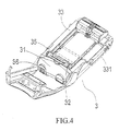
- FIG. 4 is a perspective view showing the present invention in an open condition.
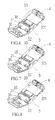
- FIG. 5 is a perspective view showing an embodiment of the present invention.
- FIG. 6 is a perspective view showing another embodiment of the present invention.
- FIG. 7 is a perspective view showing another embodiment of the present invention.
- FIG. 8 is a perspective view showing another embodiment of the present invention.
- FIG. 9 is a perspective view showing a further embodiment of the present invention.
- FIG. 10 is a perspective view showing a further embodiment of the present invention.
- FIG. 11 is a perspective view showing a further embodiment of the present invention.
- an electric power exchanging equipment 3 comprises a main body 31 .
- a lid 34 is pivotally connected to the main body 31 .
- the main body 31 forms one or more connection holes 36 .
- the main body 31 forms a containing room 32 .
- a retention member 35 is arranged inside the containing room 32 to fix a battery.
- the containing room 32 functions to receive therein a battery.
- the containing room 32 has a side edge defining a fixing block 33 .
- the fixing block 33 can be a wall.
- the fixing block 33 extends toward the containing room 32 to define a holding room 331 .
- the holding room 331 is capable of receiving therein various batteries 4 of different specifications and sizes.
- the battery 4 is fixed in position by the fixing block 33 for charging. As such, a practical advantage of positioning the battery 4 can be realized.
- the fixing block 33 of the electric power exchanging equipment 3 can be arranged in the form of a side wall having a curved surface, a cylindrical peg, and a square peg.
- the main body 31 of the electric exchanging equipment 3 has another side that is opposite to the fixing block 33 and forms a side edge 37 .
- the side edge 37 can be lower than the containing room 32 or of the same height as the containing room, or the side edge 37 can be slightly higher than the containing room 32 but not higher than the fixing block 33 .
- the battery when a battery is set to charge, the battery can be received in the holding room 331 but the battery is not limited by the side edge 37 so that the battery can extend beyond the main boy 31 and shows a positioning effect realized through engagement with the fixing block 33 .
Abstract
An electric power exchanging equipment comprises a main body which has a containing room, and a side edge of the containing room defines a battery fixing block. The fixing block extends toward the containing room in order to define a holding room for holding a battery The containing room can hold batteries of different standards and dimensions.
Description
- The present invention generally relates to an electromechanical field, and more particularly to an electric power exchanging equipment.
- It is known that consumer electronic products (such as a mobile phone, a digital camera, and an MP3) are widely used. To provide electrical power to the consumer electronic products, the consumer electronic products are often coupled with a battery to receive electrical power. The battery used is generally a secondary battery that allows of repeated recharge. Consequently, an electric charger becomes a necessary peripheral device.
- However, since new consumer electronic products are always being developed, to satisfy the desires of the modem people for innovation and distinctive personal styles, all the manufacturers make consumer electronic products with vivid configurations and coloring for distinction. Similarly, the batteries that are used in the consumer electronic products are designed devotedly for specific consumer electronic product and work with specific electric charger, making it not possible to share with electric chargers of other brands.
- An electric charger that can be commonly used with batteries of different specifications and brands is developed by the manufacturers. As shown in
FIG. 1 , the conventional electric charger 1 comprises abody 11. Thebody 11 forms a containingroom 12 that is capable of receiving and holding batteries of various specifications therein for electric charging. - As shown in
FIG. 2 , another conventionalelectric charger 2 comprises abody 21. Thebody 21 forms a containingroom 22 that is capable of receiving and holding therein various batteries of different specifications. The containingroom 22 has two sides each forming aside wall 23. With the arrangement of theside walls 23, a battery can be securely received and held in the containingroom 22 for electric charging. - However, the above described
electric chargers 1, 2 show the following problems in the use thereof: - (1) The containing
room 12 of the electric charger 1 is not provided with theside walls 23 of theelectric charger 2 and this makes it possible to receive and hold a battery of a large size. However, in charging a battery, the battery is provided with a function of fixing so that the battery can get easily detached from the containingroom 12. - (2) The containing
room 22 of theelectric charger 2 is provided with aside wall 23 at each of two sides thereof, so that when the size of a battery is excessively large, the battery cannot be received in the containingroom 22. Thus, improvement is desired. - The objective of the present invention is to provide an electric power exchanging equipment, which solves the problems that for a conventional electric charger that does not have a fixing device, a battery may get easily falling, and for a conventional electric charger that has a fixing device, it is generally not fit to a battery having an excessively large size.
- The technical solution of the present invention is that a main body is included and the main body forms a containing room for receiving and holding a predetermined battery. The containing room has a side forming a fixing block. The fixing block extends through the containing room to define a holding room. The holding room can receive and hold various predetermined batteries of different configurations and sizes.
- The fixing block can be arranged as a side wall having a curved surface, a cylindrical peg, or a square peg.
- The main body comprises a lid pivotally connected thereto.
- The containing room comprises a retention member arranged therein for retaining a battery.
- The main body forms one or more connection holes.
- The main body has another side that is opposite to the fixing block and forms a side edge.
- The present invention has the following advantages: Various batteries of different specifications and sizes can be received in the holding room and the battery can be fixed by the fixing block for electric charging, thereby realizing a function of fixing battery.
- The foregoing objectives and summary provide only a brief introduction to the present invention. To fully appreciate these and other objects of the present invention as well as the invention itself; all of which will become apparent to those skilled in the art, the following detailed description of the invention and the claims should be read in conjunction with the accompanying drawings. Throughout the specification and drawings identical reference numerals refer to identical or similar parts.
- Many other advantages and features of the present invention will become manifest to those versed in the art upon making reference to the detailed description and the accompanying sheets of drawings in which a preferred structural embodiment incorporating the principles of the present invention is shown by way of illustrative example.
-
FIG. 1 is a perspective view showing a conventional electrical charger. -
FIG. 2 is a perspective view showing another conventional electrical charger. -
FIG. 3 is a perspective view showing the present invention. -
FIG. 4 is a perspective view showing the present invention in an open condition. -
FIG. 5 is a perspective view showing an embodiment of the present invention. -
FIG. 6 is a perspective view showing another embodiment of the present invention. -
FIG. 7 is a perspective view showing another embodiment of the present invention. -
FIG. 8 is a perspective view showing another embodiment of the present invention. -
FIG. 9 is a perspective view showing a further embodiment of the present invention. -
FIG. 10 is a perspective view showing a further embodiment of the present invention. -
FIG. 11 is a perspective view showing a further embodiment of the present invention. - The following descriptions are exemplary embodiments only, and are not intended to limit the scope, applicability or configuration of the invention in any way. Rather, the following description provides a convenient illustration for implementing exemplary embodiments of the invention. Various changes to the described embodiments may be made in the function and arrangement of the elements described without departing from the scope of the invention as set forth in the appended claims.
- As shown in
FIGS. 3 and 4 , an electricpower exchanging equipment 3 according to the present invention comprises amain body 31. Alid 34 is pivotally connected to themain body 31. Themain body 31 forms one ormore connection holes 36. Themain body 31 forms a containingroom 32. Aretention member 35 is arranged inside the containingroom 32 to fix a battery. The containingroom 32 functions to receive therein a battery. The containingroom 32 has a side edge defining afixing block 33. Thefixing block 33 can be a wall. Thefixing block 33 extends toward the containingroom 32 to define aholding room 331. - As shown in
FIGS. 4 and 5 , when abattery 4 is positioned in the containingroom 32 of the electricpower exchanging equipment 3 for charging, since the containingroom 32 has a side that definesfixing block 33, in which thefixing block 33 can be a wall and thefixing block 33 extends toward the containingroom 32 to define aholding room 331, theholding room 331 is capable of receiving thereinvarious batteries 4 of different specifications and sizes. Thebattery 4 is fixed in position by thefixing block 33 for charging. As such, a practical advantage of positioning thebattery 4 can be realized. - As shown in
FIGS. 6-8 , the fixingblock 33 of the electricpower exchanging equipment 3 can be arranged in the form of a side wall having a curved surface, a cylindrical peg, and a square peg. - As shown in
FIGS. 9-11 , themain body 31 of the electric exchangingequipment 3 has another side that is opposite to the fixingblock 33 and forms aside edge 37. Theside edge 37 can be lower than the containingroom 32 or of the same height as the containing room, or theside edge 37 can be slightly higher than the containingroom 32 but not higher than the fixingblock 33. As such, when a battery is set to charge, the battery can be received in theholding room 331 but the battery is not limited by theside edge 37 so that the battery can extend beyond themain boy 31 and shows a positioning effect realized through engagement with the fixingblock 33. - It will be understood that each of the elements described above, or two or more together may also find a useful application in other types of methods differing from the type described above.
- While certain novel features of this invention have been shown and described and are pointed out in the annexed claim, it is not intended to be limited to the details above, since it will be understood that various omissions, modifications, substitutions and changes in the forms and details of the device illustrated and in its operation can be made by those skilled in the art without departing in any way from the spirit of the present invention.
Claims (6)
1. An electric power exchanging equipment, comprising a main body, the main body forming a containing room, characterized in that: the containing room has a side defining a fixing block, the fixing block extending toward the containing rook to define a holding room, the holding room being adapted to receive therein a battery.
2. The electric power exchanging equipment according to claim 1 , characterized in that: the fixing block is arranged as a wall having a curved surface, a cylindrical peg or a square peg.
3. The electric power exchanging equipment according to claim 1 , characterized in that: the main body comprises a lid pivotally connected thereto.
4. The electric power exchanging equipment according to claim 1 , characterized in that: a retention member is arranged inside the containing room for fixing the battery.
5. The electric power exchanging equipment according to claim 1 , characterized in that: the main body forms one or more connection holes.
6. The electric power exchanging equipment according to claim 1 , characterized in that: the main body has another side that is opposite to the fixing block and forms a side edge.
Applications Claiming Priority (1)
| Application Number | Priority Date | Filing Date | Title |
|---|---|---|---|
| PCT/CN2010/070176 WO2011085551A1 (en) | 2010-01-14 | 2010-01-14 | Electric power exchanging equipment |
Publications (1)
| Publication Number | Publication Date |
|---|---|
| US20120249062A1 true US20120249062A1 (en) | 2012-10-04 |
Family
ID=44303807
Family Applications (1)
| Application Number | Title | Priority Date | Filing Date |
|---|---|---|---|
| US13/517,049 Abandoned US20120249062A1 (en) | 2010-01-14 | 2010-01-14 | Electric power exchanging equipment |
Country Status (9)
| Country | Link |
|---|---|
| US (1) | US20120249062A1 (en) |
| EP (1) | EP2525436A1 (en) |
| JP (1) | JP2013515454A (en) |
| KR (1) | KR20100077400A (en) |
| CN (2) | CN201311955Y (en) |
| BR (1) | BR112012016600A2 (en) |
| CA (1) | CA2786871A1 (en) |
| TW (1) | TW201009199A (en) |
| WO (1) | WO2011085551A1 (en) |
Cited By (1)
| Publication number | Priority date | Publication date | Assignee | Title |
|---|---|---|---|---|
| USD767487S1 (en) * | 2014-12-23 | 2016-09-27 | Shenzhen Enjoylife Technology Corporation Limited | Battery charger |
Families Citing this family (3)
| Publication number | Priority date | Publication date | Assignee | Title |
|---|---|---|---|---|
| TW201009199A (en) * | 2010-01-14 | 2010-03-01 | Jye Chuang Electronic Co Ltd | Improved structure of electrical energy exchange device |
| WO2011088617A1 (en) * | 2010-01-21 | 2011-07-28 | Chang Yichang | Electric energy exchange device |
| KR101402672B1 (en) * | 2012-06-20 | 2014-06-11 | 국민대학교산학협력단 | System with anti-shaking device for auto-exchanging of electric vehicle battery |
Citations (12)
| Publication number | Priority date | Publication date | Assignee | Title |
|---|---|---|---|---|
| US5057761A (en) * | 1990-01-11 | 1991-10-15 | Eveready Battery Company, Inc. | Means for distinguishing between batteries capable of being fast charged and other batteries and for charging same accordingly |
| US6498457B1 (en) * | 1999-05-25 | 2002-12-24 | Honda Giken Kogyo Kabushiki Kaisha | Battery exchange apparatus |
| US20030085686A1 (en) * | 2001-10-09 | 2003-05-08 | Youichi Haga | Battery pack charging device |
| US20030085685A1 (en) * | 2001-10-03 | 2003-05-08 | Yutaka Usui | Battery pack charging device |
| US20070069689A1 (en) * | 2005-09-27 | 2007-03-29 | Shum King M | Battery charger |
| US20070108942A1 (en) * | 2002-11-22 | 2007-05-17 | Johnson Todd W | Method and system for protection of a lithium-based multicell battery pack including a heat sink |
| CN201025659Y (en) * | 2007-02-23 | 2008-02-20 | 捷创电子股份有限公司 | Combined structure for power exchange device |
| US20080122402A1 (en) * | 2006-11-27 | 2008-05-29 | Eveready Battery Company | Communicative battery charger |
| US20080297111A1 (en) * | 2007-06-01 | 2008-12-04 | Fisher Gary A | Alkaline battery charger with universal connectors |
| CN201311955Y (en) * | 2010-01-14 | 2009-09-16 | 捷创电子股份有限公司 | Electric energy exchange device |
| US20100194332A1 (en) * | 2009-02-05 | 2010-08-05 | Hung Hi Law | Adjustable Charger |
| US20110156645A1 (en) * | 2009-12-07 | 2011-06-30 | Samya Technology Co., Ltd. | All-in-one lithium battery charger |
Family Cites Families (5)
| Publication number | Priority date | Publication date | Assignee | Title |
|---|---|---|---|---|
| JPH0668295U (en) * | 1993-02-22 | 1994-09-22 | 怡利電子工業股▲ひん▼有限公司 | Rechargeable battery charger |
| US5365159A (en) * | 1993-10-05 | 1994-11-15 | E Lead Electronic Co., Ltd. | Battery-charger with adjustable contacts |
| JPH07335269A (en) * | 1994-06-14 | 1995-12-22 | Brother Ind Ltd | Charger |
| CN1230797A (en) * | 1998-04-02 | 1999-10-06 | 姚立和 | Recharger suitable for several sizes of mobile telephone battery |
| TW201028820A (en) * | 2009-01-17 | 2010-08-01 | Iwei Technology Co Ltd | Improved structure of recharger |
-
2008
- 2008-08-22 TW TW097144064A patent/TW201009199A/en unknown
- 2008-10-29 CN CNU2008201758473U patent/CN201311955Y/en not_active Expired - Fee Related
- 2008-12-10 CN CNA2008101860160A patent/CN101442146A/en active Pending
- 2008-12-29 KR KR1020080135323A patent/KR20100077400A/en not_active Application Discontinuation
-
2010
- 2010-01-14 BR BR112012016600A patent/BR112012016600A2/en not_active IP Right Cessation
- 2010-01-14 JP JP2012545057A patent/JP2013515454A/en active Pending
- 2010-01-14 US US13/517,049 patent/US20120249062A1/en not_active Abandoned
- 2010-01-14 EP EP10842835A patent/EP2525436A1/en not_active Withdrawn
- 2010-01-14 CA CA2786871A patent/CA2786871A1/en not_active Abandoned
- 2010-01-14 WO PCT/CN2010/070176 patent/WO2011085551A1/en active Application Filing
Patent Citations (15)
| Publication number | Priority date | Publication date | Assignee | Title |
|---|---|---|---|---|
| US5057761A (en) * | 1990-01-11 | 1991-10-15 | Eveready Battery Company, Inc. | Means for distinguishing between batteries capable of being fast charged and other batteries and for charging same accordingly |
| US6498457B1 (en) * | 1999-05-25 | 2002-12-24 | Honda Giken Kogyo Kabushiki Kaisha | Battery exchange apparatus |
| US20030085685A1 (en) * | 2001-10-03 | 2003-05-08 | Yutaka Usui | Battery pack charging device |
| US6774605B2 (en) * | 2001-10-03 | 2004-08-10 | Sony Corporation | Battery pack charging device |
| US20030085686A1 (en) * | 2001-10-09 | 2003-05-08 | Youichi Haga | Battery pack charging device |
| US6583600B2 (en) * | 2001-10-09 | 2003-06-24 | Sony Corporation | Battery pack charging device |
| US20070108942A1 (en) * | 2002-11-22 | 2007-05-17 | Johnson Todd W | Method and system for protection of a lithium-based multicell battery pack including a heat sink |
| US20070069689A1 (en) * | 2005-09-27 | 2007-03-29 | Shum King M | Battery charger |
| US20080122402A1 (en) * | 2006-11-27 | 2008-05-29 | Eveready Battery Company | Communicative battery charger |
| CN201025659Y (en) * | 2007-02-23 | 2008-02-20 | 捷创电子股份有限公司 | Combined structure for power exchange device |
| US20080297111A1 (en) * | 2007-06-01 | 2008-12-04 | Fisher Gary A | Alkaline battery charger with universal connectors |
| US20100194332A1 (en) * | 2009-02-05 | 2010-08-05 | Hung Hi Law | Adjustable Charger |
| US8183830B2 (en) * | 2009-02-05 | 2012-05-22 | Keep Smart Trading Limited | Adjustable charger |
| US20110156645A1 (en) * | 2009-12-07 | 2011-06-30 | Samya Technology Co., Ltd. | All-in-one lithium battery charger |
| CN201311955Y (en) * | 2010-01-14 | 2009-09-16 | 捷创电子股份有限公司 | Electric energy exchange device |
Cited By (1)
| Publication number | Priority date | Publication date | Assignee | Title |
|---|---|---|---|---|
| USD767487S1 (en) * | 2014-12-23 | 2016-09-27 | Shenzhen Enjoylife Technology Corporation Limited | Battery charger |
Also Published As
| Publication number | Publication date |
|---|---|
| BR112012016600A2 (en) | 2016-04-12 |
| CA2786871A1 (en) | 2011-07-21 |
| WO2011085551A1 (en) | 2011-07-21 |
| JP2013515454A (en) | 2013-05-02 |
| TW201009199A (en) | 2010-03-01 |
| CN101442146A (en) | 2009-05-27 |
| CN201311955Y (en) | 2009-09-16 |
| EP2525436A1 (en) | 2012-11-21 |
| KR20100077400A (en) | 2010-07-08 |
Similar Documents
| Publication | Publication Date | Title |
|---|---|---|
| US10320210B2 (en) | Portable power adapter with detachable battery unit | |
| US9041338B2 (en) | Portable solar power supply | |
| US9502912B2 (en) | Mobile power device | |
| US8947040B2 (en) | Universal Charger | |
| AU2013100194A4 (en) | A Power Supply | |
| EP2713471B1 (en) | Charger | |
| GB2420659B (en) | Collapsible rechargeable battery assembly with integral connector | |
| US9401609B2 (en) | Portable power transfer device | |
| US8183830B2 (en) | Adjustable charger | |
| US20120249062A1 (en) | Electric power exchanging equipment | |
| US20050189911A1 (en) | Combination mobile phone charger | |
| CN105743154A (en) | Portable battery charger having gender storage groove | |
| US20110148357A1 (en) | Battery charger base capable of connecting external AC power | |
| KR101794164B1 (en) | Auxiliary battery for portable terminal | |
| US20180219395A1 (en) | Collapsible battery charger (cbc) | |
| KR200478882Y1 (en) | Portable power pack | |
| US20140266007A1 (en) | Portable Charger | |
| US20130234650A1 (en) | Charger having a retractable seat | |
| US20140292255A1 (en) | Usb charging structure of mobile power pack | |
| CN208226610U (en) | Portable mobile power supply | |
| KR200270409Y1 (en) | A charging adapter for handphone | |
| CN206992438U (en) | Multifunctional charger baby case and bag socket device | |
| CN204424631U (en) | Multifunctional bobbin winder | |
| CN201369372Y (en) | Charger with external USB plug | |
| TWM328140U (en) | Portable charging device |
Legal Events
| Date | Code | Title | Description |
|---|---|---|---|
| STCB | Information on status: application discontinuation |
Free format text: ABANDONED -- FAILURE TO RESPOND TO AN OFFICE ACTION |