US20120249356A1 - Surface penetrating radar system and target zone investigation methodology - Google Patents
Surface penetrating radar system and target zone investigation methodology Download PDFInfo
- Publication number
- US20120249356A1 US20120249356A1 US13/075,992 US201113075992A US2012249356A1 US 20120249356 A1 US20120249356 A1 US 20120249356A1 US 201113075992 A US201113075992 A US 201113075992A US 2012249356 A1 US2012249356 A1 US 2012249356A1
- Authority
- US
- United States
- Prior art keywords
- code
- sequence
- signal
- dsss
- target zone
- Prior art date
- Legal status (The legal status is an assumption and is not a legal conclusion. Google has not performed a legal analysis and makes no representation as to the accuracy of the status listed.)
- Granted
Links
Images


Classifications
-
- G—PHYSICS
- G01—MEASURING; TESTING
- G01S—RADIO DIRECTION-FINDING; RADIO NAVIGATION; DETERMINING DISTANCE OR VELOCITY BY USE OF RADIO WAVES; LOCATING OR PRESENCE-DETECTING BY USE OF THE REFLECTION OR RERADIATION OF RADIO WAVES; ANALOGOUS ARRANGEMENTS USING OTHER WAVES
- G01S13/00—Systems using the reflection or reradiation of radio waves, e.g. radar systems; Analogous systems using reflection or reradiation of waves whose nature or wavelength is irrelevant or unspecified
- G01S13/02—Systems using reflection of radio waves, e.g. primary radar systems; Analogous systems
- G01S13/04—Systems determining presence of a target
-
- G—PHYSICS
- G01—MEASURING; TESTING
- G01S—RADIO DIRECTION-FINDING; RADIO NAVIGATION; DETERMINING DISTANCE OR VELOCITY BY USE OF RADIO WAVES; LOCATING OR PRESENCE-DETECTING BY USE OF THE REFLECTION OR RERADIATION OF RADIO WAVES; ANALOGOUS ARRANGEMENTS USING OTHER WAVES
- G01S13/00—Systems using the reflection or reradiation of radio waves, e.g. radar systems; Analogous systems using reflection or reradiation of waves whose nature or wavelength is irrelevant or unspecified
- G01S13/02—Systems using reflection of radio waves, e.g. primary radar systems; Analogous systems
- G01S13/06—Systems determining position data of a target
- G01S13/08—Systems for measuring distance only
- G01S13/10—Systems for measuring distance only using transmission of interrupted, pulse modulated waves
- G01S13/26—Systems for measuring distance only using transmission of interrupted, pulse modulated waves wherein the transmitted pulses use a frequency- or phase-modulated carrier wave
- G01S13/28—Systems for measuring distance only using transmission of interrupted, pulse modulated waves wherein the transmitted pulses use a frequency- or phase-modulated carrier wave with time compression of received pulses
- G01S13/284—Systems for measuring distance only using transmission of interrupted, pulse modulated waves wherein the transmitted pulses use a frequency- or phase-modulated carrier wave with time compression of received pulses using coded pulses
- G01S13/288—Systems for measuring distance only using transmission of interrupted, pulse modulated waves wherein the transmitted pulses use a frequency- or phase-modulated carrier wave with time compression of received pulses using coded pulses phase modulated
-
- G—PHYSICS
- G01—MEASURING; TESTING
- G01S—RADIO DIRECTION-FINDING; RADIO NAVIGATION; DETERMINING DISTANCE OR VELOCITY BY USE OF RADIO WAVES; LOCATING OR PRESENCE-DETECTING BY USE OF THE REFLECTION OR RERADIATION OF RADIO WAVES; ANALOGOUS ARRANGEMENTS USING OTHER WAVES
- G01S13/00—Systems using the reflection or reradiation of radio waves, e.g. radar systems; Analogous systems using reflection or reradiation of waves whose nature or wavelength is irrelevant or unspecified
- G01S13/88—Radar or analogous systems specially adapted for specific applications
- G01S13/885—Radar or analogous systems specially adapted for specific applications for ground probing
Landscapes
- Engineering & Computer Science (AREA)
- Radar, Positioning & Navigation (AREA)
- Remote Sensing (AREA)
- Physics & Mathematics (AREA)
- Computer Networks & Wireless Communication (AREA)
- General Physics & Mathematics (AREA)
- Electromagnetism (AREA)
- Radar Systems Or Details Thereof (AREA)
Abstract
A radar system (22) includes a transmitter (45), a receiver (59), and a software defined radio (SDR) peripheral (40). Methodology (80) for investigating a target zone (26) utilizing the system (22) entails generating (106) a direct sequence spread spectrum (DSSS) code (120) having a code length (122) corresponding to a time duration of radio wave travel between the transmitter (45), the target zone (26), and the receiver (59) at a carrier frequency (112). A beacon signal (34), modulated (108) by the DSSS code (120), is transmitted (152) from the transmitter (45) toward the target zone (26) and a return signal (38) is received (156) at the receiver (56). The return signal (38) is compared (170) to a replica signal (168) characterized by the DSSS code (120), and presence of an object (32) in the target zone (26) is ascertained (178) when the return signal (38) matches the replica signal (168).
Description
- The present invention relates to the field of surface penetrating radar systems. More specifically, the present invention relates to a surface penetrating radar system using a spread spectrum methodology for controlling penetration distance.
- Surface penetrating radar, also referred to as ground penetrating radar (GPR), is used to investigate the surface and subsurface features of a target zone or area. In general, GPR uses transmitting and receiving antennas, or only one antenna containing both functions. The transmitting antenna typically radiates short pulses of high-frequency radio waves into the ground. When the wave hits a buried object or a boundary with different electromagnetic properties, the wave is reflected from the object or boundary, and a receiving antenna records the reflected return signal. The return signals can be used to locate and/or construct an image of what is underground because the return signals will vary depending on the depth and composition of buried objects.
- There are many applications for GPR in a number of fields. For example, GPR is used in the Earth sciences to study bedrock, soils, groundwater, and ice. Engineering applications include nondestructive testing (NDT) of structures and pavements, locating buried structures and utility lines, and studying soils and bedrock. In environmental remediation, GPR is used to define landfills, contaminant plumes, and other remediation sites, while in archaeology it is used for mapping archaeological features and cemeteries. GPR is used in law enforcement for locating clandestine graves and buried evidence, and military uses include detection of buried mines and unexploded ordnance as well as subterranean tunnels and fortifications.
- Aerial or airborne GPR systems are advantageous in regions where direct contact with the ground is impossible or dangerous, and/or in regions where non-invasive radar imaging is to take place. Existing airborne GPR systems are broad band, complex, heavy, and require large and expensive to operate aircraft to carry the GPR systems. Additionally, the wide bandwidth of conventional GPR systems can cause distortion, i.e., frequency dependent attenuation, and dispersion, i.e., frequency dependent velocity, which can greatly limit the penetration distance and reflection time resolution. Thus, systems that achieve improved penetration distance and reflected signal recovery, while concurrently achieving reduced cost, size, and weight are needed so that ground penetrating radar can be more extensively and usefully employed.
- A more complete understanding of the present invention may be derived by referring to the detailed description and claims when considered in connection with the Figures, wherein like reference numbers refer to similar items throughout the Figures, and:
-
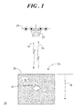
FIG. 1 shows a diagram of an environment in which an airborne radar system may be implemented in accordance with an embodiment of the present invention; -
FIG. 2 shows a block diagram of the airborne radar system of the present invention; -
FIG. 3 shows a diagram of a software defined radio implementation of the radar system ofFIG. 2 ; -
FIG. 4 shows a flowchart of a surface penetrating investigation process performed by the radar system ofFIG. 1 ; -
FIG. 5 shows a diagram of a direct sequence spread spectrum (DSSS) implementation of the present invention; -
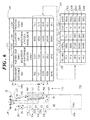
FIG. 6 shows a simplified exemplary scenario in which process gain for the radar system is dynamically controlled; -
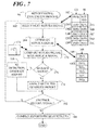
FIG. 7 shows a flowchart of a return signal evaluation process executed in accordance with an embodiment of the present invention; -
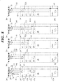
FIG. 8 shows a diagram representing the transmission of a beacon signal modulated by a set of DSSS codes having increasingly longer code lengths in order to investigate a target zone at increasingly greater penetration distances; and -
FIG. 9 shows a chart illustrating a presentation of results compiled in accordance with execution of the return signal evaluation process and with respect to the diagram ofFIG. 8 . - Embodiments of the invention entail a surface penetrating radar system and associated methodology for investigating the surface and subsurface of a target zone. The radar system and methodology implement a narrow bandwidth direct sequence spread spectrum (DSSS) code. The narrow bandwidth can minimize frequency dependent dispersion and distortion. In addition, the DSSS code enables greater process gains for adaptation to different distances of subsurface penetration and improved reflected signal recovery. A long, DSSS coded, narrow bandwidth radar waveform signal advantageously enables the energy of the waveform to be distributed over the entire DSSS code sequence so that peak power requirements of the transmitter can be greatly reduced. The relatively low peak power requirements of the radar system allow smaller and lighter radar components suitable for airborne applications, such as manned aircraft and unmanned aerial vehicles (UAV).
-
FIG. 1 shows a diagram of anenvironment 20 in which anairborne radar system 22 may be implemented in accordance with an embodiment. In an embodiment,radar system 22 is housed at a reference platform, and more particularly, an airborne platform, such as a manned airplane, a helicopter, an unmanned aerial vehicle, a satellite, a spacecraft, and so forth. The reference platform in this example is anairplane 24 flying over atarget zone 26 of interest.Target zone 26 may be asurface 28 and/orsubsurface region 30 of the earth or another planet. In this illustration,target zone 26 may be investigated byradar system 22 in order to detect the presence of anobject 32 or objects insubsurface region 30. Alternatively,radar system 22 may be used to detect the presence ofobject 32 when it is located onsurface 28, but is hidden by foliage, buildings, fortifications, and so forth. -
Radar system 22 is discussed below in connection with an airborne platform and investigating the surface and subsurface of the earth. However,radar system 22 is not limited to use in an airborne platform. In alternative embodiments, the reference platform at whichradar system 22 is located may be a tower, a mountain, a stand, and so forth, such that the reference platform is positioned at or near the surface of interest. Nor isradar system 22 limited for use in ground penetrating scenarios. In alternative embodiments,radar system 22 may be used to investigate target zones by penetration through the side surface of a building, and the like. -
Object 32 may be an item such as a buried structure, a utility line, an archeological feature, a grave, buried evidence, a buried mine, wire for an improvised explosive device (IED), unexploded ordnance, subterranean tunnel, and so forth. In alternative embodiments,object 32 may be a boundary between different materials or media such as various layers of bedrock, soils, groundwater, ice, and so forth. In general,object 32 represents media with different intrinsic electromagnetic properties than its surroundings. These electromagnetic properties can include, for example, a dielectric constant, conductivity, magnetic permeability, and so forth. - As will be described in detail below, a
beacon signal 34 is transmitted fromradar system 22.Beacon signal 34 is adapted to penetrate target zone 26 apredetermined penetration distance 36 at or belowsurface 28. The particular modulation scheme for generatingbeacon signal 34 enables penetration ofbeacon signal 34 to thepredetermined penetration distance 36. Ifbeacon signal 34 comes into contact withobject 32,beacon signal 34 is reflected back toradar system 22 as areturn signal 38.Return signal 38 can subsequently be used to locate and/or construct an image ofobject 32 atsurface 28 or insubsurface 30. - Referring to
FIGS. 2-3 ,FIG. 2 shows a block diagram ofairborne radar system 22 andFIG. 3 shows a diagram of a software defined radio implementation ofradar system 22. In an embodiment,radar system 22 generally includes a software defined radio (SDR) peripheral 40, aninput device 42 in communication with SDR peripheral 40, and anoutput device 44 in communication with SDR peripheral 40. -
Input device 42 can encompass buttons, switches, a keyboard, mouse, pointing device, audio device (e.g., a microphone), and/or any other device providing input to SDR peripheral 40.Output device 44 can encompass a display, a printer, an audio device (e.g., a speaker), and/or other devices providing output from SDR peripheral 40. Input andoutput devices - A
transmitter portion 45 ofradar system 22 includes atransmit output 46 of SDR peripheral 40 in communication with apower amplifier 48, which is in communication with amatching network element 50. Anoutput 52 of matchingnetwork element 50 is in communication with atransmit input 54 of a transmit/receiveswitch 56. Transmit/receiveswitch 56 is in communication with anantenna system 58. Areceiver portion 59 ofradar system 22 includes afilter 60 having aninput 62 in communication with areceive output 64 of transmit/receiveswitch 56.Filter 60 is in communication with apre-amplifier 66, andpre-amplifier 66 is in communication with a receiveinput 68 of SDR peripheral 40. - Transmit/receive
switch 56 is controlled by SDR peripheral 40 via acontrol link 70 to be in a transmit mode or a receive mode. For example, SDR peripheral 40 is configured to send a transmit enablesignal 72 to switch 56 so thatswitch 56 is enabled to allow transmission ofbeacon signal 34, with its receive capability being disabled. Alternatively, SDR peripheral 40 can send a receive enablesignal 74 to transmit/receiveswitch 56 so thatswitch 56 is enabled to allow receipt ofreturn signal 38, with its transmit capability being disabled. - In general, SDR peripheral 40 generates
beacon signal 34 andoutputs beacon signal 34 via transmitoutput 46 topower amplifier 48 where beacon signal 34 is suitably amplified.Beacon signal 34 is output frompower amplifier 48 to matchingnetwork element 50 where impedance matching is performed for the maximum transfer of power from the source to the load. Next,beacon signal 34 is communicated to transmit/receiveswitch 56. When transmit/receiveswitch 56 is in the transmit mode governed by transmit enablesignal 72,beacon signal 34 is output fromradar system 22 viaantenna 58. - Following output of
beacon signal 34, transmit/receiveswitch 56 is switched to the receive mode as governed by receive enablesignal 74 so thatreturn signal 38 can be received atradar system 22.Return signal 38 detected atantenna 58 is communicated to transmit/receiveswitch 56. Next, returnsignal 38 is communicated fromswitch 56 to filter 60 in order to filter spurious signals and other signal noise.Return signal 38 is then communicated fromfilter 60 topre-amplifier 66. Reflected signals, such asreturn signal 38, reflected back toantenna 58 are typically very weak. Thus,pre-amplifier 66 suitably amplifies or strengthensreturn signal 38 for processing. Following amplification, returnsignal 38 may be input at receiveinput 68 of SDR peripheral 40. SDR peripheral 40 may perform signal evaluation (discussed below) ofreturn signal 38 in order to ascertain the presence of one or more objects 32 (FIG. 1 ) intarget zone 26. Alternatively, one or more return signals 38 may be output from SDR peripheral 40 for off-line processing by another computing system (not shown). - In an embodiment, processing, transmitting, and receiving functions of
radar system 20 are implemented and controlled within SDR peripheral 40. A software defined radio system, such as SDR peripheral 40, is a radio communication system where components that have been typically implemented in hardware are instead implemented by means of software. As such, SDR peripheral 40 can provide software control of its functions, such as wide- or narrow-band operation, modulation techniques, security functions, analog-to-digital and digital-to-analog conversions, and so forth. Such a design produces a radio system which can receive and transmit widely different radio protocols (i.e., waveforms) based solely on the software used. - SDR peripheral 40 may include a main board, sometimes referred to as a motherboard, and one or more daughter-boards acting as extensions to the motherboard that cover different input/output frequencies, and so forth. The motherboard, daughter-boards, and any other processor capability is represented in SDR peripheral 40 by a
processor 76. As mentioned above, components that have typically been implemented in hardware are instead implemented by means of software in SDR peripheral 40. Thus, SDR peripheral 40 further includes amemory element 78 that is in communication withprocessor 76. -
Memory element 78 hasexecutable code 80 stored therein, that instructsprocessor 76 to perform a number of operations pertinent to the function ofradar system 22.Memory element 78 may be any volatile or non-volatile mass storage system readable byprocessor 76.Memory element 78 may also include cooperating or interconnected computer readable media, which exist exclusively on SDR peripheral 40 or are distributed among multiple interconnected computing systems (not shown) that may be local or remote. -
Executable code 80 can include a surface penetratinginvestigation process 82 and a returnsignal evaluation process 84. In an exemplary scenario, surface penetratinginvestigation process 82 can include software code modules that perform transmitsequence generation 86,waveform generation 88, modulation functions 90, transmitfunctions 92,switch control 94, and receive functions 96. Returnsignal evaluation process 84 can include software code modules that perform receivesequence generation 98, demodulation functions 100, return signal evaluation functions 102, and report generation functions 104. - Those skilled in the art will recognize that the software functions performed by SDR peripheral 40 can vary from that which is shown and can be organized differently from that which is shown. Furthermore, although embodiments are described herein as being implemented in a software defined radio architecture, various functions of
radar system 22 can alternatively be implemented in hardware. Additionally, various functions and components ofradar system 22 may be implemented at different locations. For example, in a hardware implementation,transmitter portion 45 ofradar system 22 need not be co-located with thereceiver portion 59. Likewise,processor 76 ofradar system 22 need not be co-located with either of the transmitter orreceiver portions -
FIG. 4 shows a flowchart of surface penetratinginvestigation process 82 performed by radar system 22 (FIG. 2 ). In general, surface penetratinginvestigation process 82 is executed to generate beacon signal 34 (FIG. 1 ) using spread spectrum techniques, to transmitbeacon signal 34 toward target zone 26 (FIG. 1 ), and to receive return signal 38 (FIG. 1 ). - Surface penetrating
investigation process 82 begins with atask 106. Attask 106, direct sequence spread spectrum (DSSS) code (discussed below) is generated. - In response to
task 106, atask 108 is performed. Attask 108, a signal waveform is modulated using the “next” DSSS code generated attask 106 to produce beacon signal 34 (FIG. 1 ). It should be understood that at a first iteration oftask 108, the “next” DSSS code is a first DSSS code in a set of one or more DSSS codes generated attask 106. - Referring to
FIG. 5 in connection withtasks FIG. 5 shows a diagram of a direct sequence spread spectrum (DSSS) implementation of the present invention. DSSS is a spread spectrum modulation technique in which the transmitted signal is spread out in the time-domain, while the pulse bandwidth and amplitude is reduced in the frequency-domain. A receiver compresses this time sequence back into a pulse, hence the often-used term of pulse compression. DSSS code phase-modulates a sine wave pseudorandomly with a continuous string of pseudo-noise (PN) code symbols, typically referred to as “chips.” This continuous string of PN chips is referred to as a pseudo-noise (PN) sequence. Because of the low power density inherent in spread spectrum modulation, recovery of baseband information from the spread spectrum signal can be accomplished only through correlating the received signal (plus noise) with an exact replica of the transmitted signal. A spread-spectrum receiver can use non-coherent demodulation, matched filtering, and stacking to detect the known signal buried in noise. This signal processing method permits signal detection in high noise environments. - As shown in
FIG. 5 , acontinuous wave signal 110, for example, a sine wave, is provided.Continuous wave signal 110 may be generated at SDR peripheral 40 by executing waveform generation software code module 88 (FIG. 3 ) of executable code 80 (FIG. 3 ). Of course in alternative embodiments,continuous wave signal 110 may be provided via a hardware oscillator (not shown). Continuous wave signal 110 exhibits afrequency 112, FC, that can be any of various useable carrier frequencies forcontinuous wave signal 110, such as 250 MHz, 500 MHz, 1 GHz, 5 GHz, and the like. -
FIG. 5 further illustrates an exemplary pseudo-noise (PN)sequence 114. In accordance withtask 106 of surface penetrating investigation process 82 (FIG. 4 ),PN sequence 114 may be generated at SDR peripheral 40 by executing transmit sequence generation software code module 86 (FIG. 3 ) of executable code 80 (FIG. 3 ). In an embodiment,PN sequence 114 is based on a maximal-length, binary sequence (m-sequence) ofchips 116. Achip 116 is the fundamental unit ofPN sequence 114 and can be either a one (1) or a zero (0). Thus,PN sequence 114 includes a sequence of ones and zeros (chips 116) and is typically generated by a linear feedback shift register of length, N. This sequence ofchips 116 is referred to as a “pseudo-noise” sequence because they are similar to noise and satisfy one or more of the standard tests for statistical randomness. - A
sequence length 118, L, ofPN sequence 114 is related to the number ofchips 116 inPN sequence 114, expressly,sequence length 118 is 2N-1 “chips” 116 long, where N is the number of stages in the linear feedback shift register. An arrangement of the feedback taps of the linear feedback shift register establish thedeterministic PN sequence 114 produced. Hence,different PN sequences 114 of thesame sequence length 118 have a very low cross correlation product and are said to be orthogonal. For brevity, only a portion ofPN sequence 114 is shown, whereadditional chips 116 ofPN sequence 114 are represented by ellipses located withinPN sequence 114. - In conventional DSSS for communication systems, a data signal that is intended for transmission is coded or modulated by a DSSS code, e.g.,
PN sequence 114, and this combined DSSS signal output can then be used to modulate a carrier wave, e.g.,continuous wave signal 110. However, in an embodiment,continuous wave signal 110, and hence modulatedbeacon signal 34, is absent a data signal component. That is, no data is being transmitted. Under such a circumstance,continuous wave signal 110 may be referred to as a zero payload carrier signal. Instead,beacon signal 34 is only a function ofPN sequence 114 andcontinuous wave signal 110. Accordingly,beacon signal 34 is a radar signal that is referred to as a “beacon” and radar system 22 (FIG. 1 ) operates in “beacon mode” becausesignal 34 is used for location identification purposes, rather than for transmitting a data signal. - In an embodiment,
PN sequence 114 is expanded to produce a direct sequence spread spectrum (DSSS)code 120 that will be used in phase shift modulatingcontinuous wave signal 110. For brevity, only a small portion ofDSSS code 120 is shown, whereadditional chips 116 ofDSSS code 120 are represented by ellipses located on opposing ends ofDSSS code 120. In accordance with a preferred embodiment,DSSS code 120 has acode length 122, CODEL, that is a function ofsequence length 118 ofPN sequence 114 and achip expansion factor 124.Chip expansion factor 124 defines a number of cycles ofcontinuous wave signal 110 used to represent eachchip 116 inPN sequence 114, and is an integer number that is preferably greater than one. Said another way, eachchip 116 inPN sequence 114 may be represented by multiple cycles ofcontinuous wave signal 110, as specified bychip expansion factor 124.Chip expansion factor 124 is applied toPN sequence 114 to yieldDSSS code 120 of aparticular code length 122. - As presented in
FIG. 5 for illustrative purposes,chip expansion factor 124 is shown as being the integer number four (4).Chip expansion factor 124 is applied toPN sequence 114 by successively replicating eachchip 116 inPN sequence 114 bychip expansion factor 124 to yieldDSSS code 120. In this example, each instance ofchip 116 that is the binary digit “1” inPN sequence 114 is expanded to four (4)chips 116 of the binary digit “1” inDSSS code 120. Likewise, each instance ofchip 116 that is the binary digit “0” inPN sequence 114 is expanded to four (4)chips 116 of the binary digit “0” inDSSS code 120. In this example wherechip expansion factor 124 is four (4) cycles of continuous wave signal 110 perchip 116 ofPN sequence 114,code length 122 ofDSSS code 120 is four times greater thansequence length 118 ofPN sequence 114. The selection ofsequence length 118 andchip expansion factor 124 forDSSS code 120 will be discussed in connection with an example presented inFIG. 6 . - In accordance with
task 108, DSSS code 120 (characterized byPN sequence 114 and expanded by chip expansion factor 124) is used to modulatecontinuous wave signal 110 by, for example, phase-shift keying. Phase-shift keying is a digital modulation scheme that typically conveys data by changing, or modulating, the phase of a reference signal (the carrier wave). As illustrated inFIG. 5 , eachchip 116 ofDSSS code 120 can be either the binary digit “1” or the binary digit “0.” The change from a “0”chip 116 to a “1”chip 116, and the change from a “1”chip 116 to a “0”chip 116, is represented by aphase change 126 incontinuous wave signal 110. Aphase change 126 from “0”chip 116 to “1”chip 116 is presented in anenlarged view 128 ofbeacon signal 34 for illustrative purposes. - In a spread spectrum system, such as
radar system 22, the process gain (also referred to as “processing gain”) is the ratio of the spread (or radiofrequency) bandwidth to the unspread (or baseband) bandwidth. That is, the process gain helps to measure the performance advantage of spread spectrum against narrowband waveforms. In accordance with an embodiment,radar system 22 uses a sliding correlator, i.e., a matched filter, at SDR peripheral 40 to search forDSSS code 120 in return signal 38 (FIG. 1 ). WhenDSSS code 120 is matched perfectly (in time) with a replica signal (discussed below) all of the energy inDSSS code 120 is added coherently, forming a correlation peak. The height of the correlation peak compared to the non-peak is this process gain. Thus, the process gain can be viewed as a signal to noise ratio at the receiver as the height of the correlation peak, i.e. the signal to noise ratio after the dispreading operation in whichPN sequence 114 is removed. - As further shown in
FIG. 5 , aprocess gain 130, PG, can be expressed as a function ofcode length 122 ofDSSS code 120, wherecode length 122 is a product ofsequence length 118 ofPN sequence 114 andchip expansion factor 124. That is, process gain 130 is 10 log(CODEL) expressed in decibels, dB, wherecode length 122, CODEL, is (L×CEF). Accordingly, process gain 122 is a function of bothsequence length 118 andchip expansion factor 124. -
PN sequence 114 can theoretically haveunlimited sequence length 118. Typical values forsequence length 118 are one thousand twenty three (1023) or two thousand forty seven (2047)chips 116 long. Furthermore,chip expansion factor 124 is preferably selected to be greater than one such that a bandwidth ofbeacon signal 34 is approximately equal tofrequency 112 divided bychip expansion factor 124. In an example,sequence length 118 of two thousand forty seven (2047) chips andchip expansion factor 124 of five hundred and twelve (512) cycles per chip yields process gain 130 of sixty (60) decibels. - In the software defined radio approach of radar system 22 (
FIG. 1 ), process gain 130 can be dynamically controlled viasequence length 118 andchip expansion factor 124 from one transmittedbeacon signal 34 to the next transmittedbeacon signal 34. That is,sequence length 118 ofPN sequence 114 and/orchip expansion factor 124 can be advantageously varied to provide sufficient process gain 130 so as to enable penetration ofbeacon signal 34 into target zone 26 (FIG. 1 ) at desired penetration distances 36 (FIG. 1 ) and detection of the reflectedreturn signal 38 fromtarget zone 26. - Referring now to
FIG. 6 ,FIG. 6 shows a simplifiedexemplary scenario 132 in which process gain 130 forradar system 22 is dynamically controlled to enable penetration ofbeacon signal 34 intotarget zone 26 and detection of the reflectedreturn signal 38 fromtarget zone 26 at desired penetration distances 36 at or belowsurface 28. More particularly, a suitable sequence length, L, 118 and chip expansion factor, CEF, 124, are selected for apredetermined frequency 112, FC, of continuous wave signal 110 (FIG. 5 ) to yieldDSSS code 120 havingcode length 122 corresponding to the time duration of radio wave travel between transmitter portion 45 (FIG. 2 ),target zone 26, and receiver portion 59 (FIG. 2 ) ofradar system 22.Code length 122 is represented inexemplary scenario 132 ofFIG. 5 by the curved arrow representing the round trip time duration of signal transmission and return. - In this example, a set of
DSSS codes 120 having differing process gains 130 may be generated in order to achieve different penetration distances 36 intotarget zone 26. Accordingly,target zone 26 may be subdivided into a plurality ofzone sections 134 of varying distances at or belowsurface 28. Next, astandoff distance 136 is determined betweenairplane 24 and a boundary of interest, referred to herein as anonset boundary 138, of each ofzone sections 134. In this example,standoff distance 136 betweenonset boundary 138 for a first one of zone sections 134 (labeled Z1) andairplane 24 is three hundred and three (303) meters.Standoff distance 136 betweenonset boundary 138 of a second one of zone sections 134 (labeled Z2) andairplane 24 is seven hundred and fifty seven (757) meters, and so forth. -
Standoff distance 136 demarcates ablind zone 140 for receiver portion 59 (FIG. 2 ) during whichreceiver portion 59 is disabled so thatreturn signal 38 will not be received.Standoff distance 136 further establishes apredetermined query distance 141. In this example,zone sections 134 belowstandoff distance 136 are considered within thequery distance 141, i.e., at the depth to be investigated byradar system 22. - At each
standoff distance 136, aroundtrip time duration 142 for travel of continuous wave signal 110 (FIG. 5 ) can be determined. In general, radio waves, such ascontinuous wave signal 110, can travel at the speed of light, i.e., 300,000 km/sec, in free space. However, as known to those skilled in the art, the actual speed of radio waves, i.e., the propagation velocity, changes according to the material that the radio wave is traveling through. That is, radio waves traveling in free space will travel at the speed of light, whereas, radio waves traveling in media other than free space tend to travel slower than the speed of light. For simplicity herein,roundtrip time duration 142 is determined forcontinuous wave signal 110 traveling in free space. For example, sincestandoff distance 136 betweenonset boundary 138 of a first one of zone sections 134 (labeled Z1) andairplane 24 is three hundred and three (303) meters, the roundtrip distance is six hundred and six (606) meters. Consequently,roundtrip time duration 142 is 606 m/300,000 km/sec, or 2.02 microseconds. Thus,roundtrip time duration 142 can be readily determined for eachstandoff distance 136. Each determinedroundtrip time duration 142 is presented in a first table 144 associated withstandoff distance 136. - At the
predetermined frequency 112 of continuous wave signal 110 (FIG. 5 ), and in this example at 1 GHz, a quantity of cycles ofcontinuous wave signal 110 will occur, i.e., propagate during roundtrip time duration 142. For example, atroundtrip time duration 142 of 2.02 microseconds, a quantity of cycles available value 146 is therefore 1 GHz multiplied by 2.02 microseconds, or 2020 cycles available. Thus, quantity of cycles available value 146 atfrequency 112 can be readily determined for eachroundtrip time duration 142. Each value 146 is presented in first table 144 associated with roundtrip time duration 142 andstandoff distance 136. - In a preferred embodiment,
DSSS code 120 is generated such thatcode length 122, i.e.,sequence length 118 of PN sequence 114 (FIG. 5 ) expanded bychip expansion factor 124, corresponds to a time duration of radio wave travel between transmitter portion 45 (FIG. 2 ),target zone 26, and receiver portion 59 (FIG. 2 ) at a givenfrequency 112 ofcontinuous wave signal 110. More particularly,DSSS code 120 is generated havingcode length 122 approximately equivalent toroundtrip time duration 142 for transmission of a single instance ofDSSS code 120 atfrequency 112 betweenairborne platform 24 and transmitter andreceiver portions radar system 22. Each chip 116 (FIG. 5 ) ofDSSS code 120 is represented by, or corresponds with, a single cycle ofcontinuous wave signal 110 atfrequency 112. Accordingly, a desiredcode length 122 for eachDSSS code 120 is approximately equal to quantity of cycles available value 146 atfrequency 112. - As discussed in connection with
FIGS. 5 and 6 ,process gain 130, PG, can be expressed as a function ofcode length 122 ofDSSS code 120. Accordingly, sincecode length 122 is approximately equal to quantity of cycles available value 146 of continuous wave signal 110 (FIG. 5 ) atfrequency 112, process gain 130 can be readily computed as 10 times log of value 146, expressed in decibels, dB. As shown, process gain 130 needed to achieve theappropriate query distance 141 and still receive a detectable reflection, i.e., returnsignal 38 for the first one ofzone sections 134, labeled Z1, is 33.1 dB.Process gain 130 needed to achieve theappropriate penetration distance 141 for the second one ofzone sections 134, labeled Z2, is 37.0 dB.Process gain 130 needed to achieve theappropriate penetration distance 141 for the third one ofzone sections 134, labeled Z3, is 40.0 dB, and so forth. - Once process gain 130 is determined for each of
zone sections 134, asuitable sequence length 118 andchip expansion factor 124 can be selected to generateDSSS code 120 havingcode length 122. A second table 148 presented inFIG. 6 illustrates anexemplary sequence length 118 andchip expansion factor 124 for eachDSSS code 120. For example,sequence length 118, for PN sequence 114 (FIG. 5 ) is selected to be 511 (2N-1, where N=9) andchip expansion factor 124 is selected to be 4 so that afirst DSSS code 120A hascode length 122 of 2044, and therefore process gain 130 of approximately 33.1 dB. Likewise,sequence length 118, for PN sequence 114 (FIG. 5 ) is also selected to be 511, butchip expansion factor 124 is selected to be 9 so that asecond DSSS code 120B hascode length 122 of 4599, and therefore process gain 130 of approximately 37 dB. - It should be noted that with first and
second DSSS codes 120 B sequence length 118 stays the same, butchip expansion factor 124 changes to achieve the desired process gains 130. However, it should be understood that in alternative embodiments,chip expansion factor 124 may be held constant for each ofDSSS codes 120, andsequence length 118 may be varied. This condition is illustrated in connection with athird DSSS code 120C and afourth DSSS code 120D. Alonger sequence length 118 for PN sequence 114 (FIG. 5 ), but a lowerchip expansion factor 124, can achieve better noise cancellation effects but at the price of a wider bandwidth. Conversely, longerchip expansion factor 124 can narrow the bandwidth, perhaps sacrificing some noise cancellation effects. SinceDSSS codes 120 are generated by SDR 40 (FIG. 2 ) executing transmit sequence generation code module 86 (FIG. 3 ), process gain 130 can be dynamically controlled by selecting the appropriate sequence length, L, 118 and chip expansion factor, CEF, 124, for apredetermined frequency 112, FC, of continuous wave signal 110 (FIG. 5 ) and taking into account various environmental factors. - Referring back to surface penetrating investigation process 82 (
FIG. 4 ), execution oftask 106 can yield at least oneDSSS code 120. Preferably execution oftask 106 can yield a set of DSSS codes, e.g.,DSSS code 120A,DSSS code 120B,DSSS code 120C,DSSS code 120D, and aDSSS code 120E (FIG. 6 ), for investigating various zone sections 134 (FIG. 6 ) of target zone 26 (FIG. 6 ). The one ormore DSSS codes 120 may be stored at SDR peripheral 40, or alternatively,DSSS codes 120 may be generated immediately prior to execution ofmodulation task 108. In either instance, followingtask 108 in whichcontinuous wave signal 110 is modulated using a “next” one ofDSSS codes 120,process 82 continues with atask 150. - At
task 150,radar system 22 is switched to transmit capability and receive capability is disabled. For example, transmit enable signal 72 (FIG. 2 ) may be generated at SDR peripheral 40 and communicated to transmit/receive switch 56 (FIG. 2 ) via control link 70 (FIG. 2 ) by executing switch control code module 94 (FIG. 3 ) of executable code 80 (FIG. 3 ). - Process control continues with a
task 152. Attask 152, beacon signal 34 (FIG. 2 ) is transmitted for a time duration sufficient to output a single instance ofDSSS code 120. Transmission ofbeacon signal 34 may be performed at transmitter portion 45 (FIG. 2 ) ofradar system 22 through execution of transmit function code module 92 (FIG. 3 ) of executable code 80 (FIG. 3 ). By way of example, during a first iteration of transmittask 152,beacon signal 34 may be modulated byfirst DSSS code 120A (FIG. 6 ) and is thus transmitted from radar system for approximately 2.02 microseconds, i.e., equivalent to roundtrip time duration 142 (FIG. 6 ), in order to transmit one instance ofDSSS code 120A. - Following
task 152,process 82 continues with atask 154. Attask 154,radar system 22 is switched to receive capability and transmit capability is disabled. For example, receive enable signal 74 (FIG. 2 ) may be generated at SDR peripheral 40 and communicated to transmit/receive switch 56 (FIG. 2 ) via control link 70 (FIG. 2 ) by executing switch control code module 94 (FIG. 3 ) ofexecutable code 80. - In response to switching
task 154, surface penetratinginvestigation process 82 continues with atask 156. Attask 156, return signal 38 (FIG. 2 ) is received at receiver portion 59 (FIG. 2 ) ofradar system 22. Receipt ofreturn signal 38 may be performed through execution of receive function code module 96 (FIG. 3 ) ofexecutable code 80. Referring briefly toFIG. 6 , returnsignal 38 may be a reflection signal fromobject 32 that is deeper thanstandoff distance 136. For example,DSSS code 120A havingcode length 122 of 2044 queries distances greater thanstandoff distance 136 of 303.DSSS code 120B havingcode length 122 of 4599 queries distances (predetermined query distances) greater thanstandoff distance 136 of 757, and so forth. The receivedreturn signal 38 may then be saved in, for example,memory element 78 of SDR peripheral 40 for later processing. - With reference back to
FIG. 4 , followingtask 156,process 82 continues with aquery task 158. Attask 158, a determination is made as to whether execution of surface penetratinginvestigation process 82 is to continue. For example, when adifferent DSSS code 120 is to be used for transmission, program control loops back totask 108 to modulate continuous wave signal 110 (FIG. 5 ) using the “next”DSSS code 120 to producebeacon signal 34, to subsequently transmitbeacon signal 34, and receivereturn signal 38. Referring briefly toFIG. 6 , in a next iteration oftask 108,second DSSS code 120B may be selected for use in modulatingcontinuous wave signal 110. However, in yet another example, the “next”DSSS code 120 may be thesame DSSS code 120 that was used previously to modulatecontinuous wave signal 110. When a determination is made atquery task 158 that execution of surface penetratinginvestigation process 82 is to be discontinued,process 82 ends with one or more return signals 38 having been received that may be evaluated instantly or off-line. -
FIG. 7 shows a flowchart of return signal evaluation process 84 (FIG. 3 ) executed in accordance with an embodiment of the present invention. In general, returnsignal evaluation process 84 is executed to evaluate one or more return signals 38 collected during execution of surface penetrating investigation process 82 (FIG. 4 ) in order to ascertain a presence of object 32 (FIG. 1 ) in target zone 26 (FIG. 1 ). In the illustrated embodiment, returnsignal evaluation process 84 is executed at SDR peripheral 84. However, in alternative embodiments, returnsignal evaluation process 84 may be performed off-line using one or more alternative computing systems. -
Process 84 begins with atask 160. Attask 160, a next return signal 38 (FIG. 1 ) is selected for evaluation. It should be understood that at a first iteration oftask 160, the “next”return signal 38 is afirst return signal 38 in a set of one return signals 38 received and saved at task 156 (FIG. 4 ) of surface penetration investigation process 82 (FIG. 4 ). An exemplary table 162 is presented inFIG. 7 in connection withtask 160. Table 162 represents a storage element at which return signals 38, for example, afirst return signal 38A, asecond return signal 38B, athird return signal 38C, afourth return signal 38D, and a fifth return signal 38E were stored in connection with information identifying a particular one of DSSS codes, for example,first DSSS code 120A,second DSSS code 120B,third DSSS code 120C,fourth DSSS code 120D, andfifth DSSS code 120E, that was transmitted toward target zone 26 (FIG. 1 ). During a first iteration oftask 160,first return signal 38A may be selected from table 162. -
Evaluation process 84 continues with atask 164. Attask 164, a replica signal of the selectedreturn signal 38 is generated. The replica signal may be generated at SDR peripheral 40 by executing receive sequence generation code module 98 (FIG. 3 ) of executable code 80 (FIG. 3 ). For illustrative purposes, another exemplary table 166 is presented inFIG. 7 in connection withtask 164. Table 166 represents a compilation of replica signals 168. In this example, execution oftask 164 may result in the generation of afirst replica signal 168A characterized byDSSS code 120. More particularly,first replica signal 168A is a spread code identical toDSSS code 120A.First replica signal 168A may be generated by expanding PN sequence 114 (FIG. 5 ) by chip expansion factor 124 (FIG. 5 ) forfirst DSSS code 120A. - In response to
task 164, atask 170 is performed. Attask 170, the selected one of return signals 38, e.g.,first return signal 38A, is compared withreplica signal 168, e.g.,first replica signal 168A, generated attask 164. Attask 170, demodulation function code module 100 (FIG. 3 ) and return signal evaluation function 102 (FIG. 3 ) of executable code 80 (FIG. 3 ) may be executed to implementcomparison task 170. For example, at receiver portion 59 (FIG. 2 ),return signal 38 is demodulated to extractDSSS code 120 from continuous wave signal 110 (FIG. 5 ). Next, a sliding correlator function, also referred to as a matched filter, may be used to detect the presence ofDSSS code 120 in the demodulatedreturn signal 38. WhenDSSS code 120A infirst return signal 38A matches perfectly in time withfirst replica signal 168A, all of the energy inDSSS code 120A offirst return signal 38A is added coherently forming a correlation peak. Atypical correlation peak 172 ofDSSS code 120 is presented in agraph 174 inFIG. 7 . - A
query task 176 is performed in connection withtask 170. Aquery task 176, a determination is made as to whetherreturn signal 38, e.g.,first return signal 38A, containsDSSS code 120 that matchesreplica signal 168, e.g.,first replica signal 168A. When a determination is made atquery task 176 that returnsignal 38 containsDSSS code 120matching replica signal 168,return signal 38 is indeed a reflection of beacon signal 34 (FIG. 1 ) from object 32 (FIG. 1 ). That is,object 32 having different electromagnetic properties than the surrounding media has been detected. As such, program control proceeds to atask 178. - At
task 178, a report or results may be generated identifying the detection ofobject 32. Alternatively, when a determination is made atquery task 176 that returnsignal 38 does not containsDSSS code 120matching replica signal 168, then returnsignal 38 is not a reflection of beacon signal 34 (FIG. 1 ) from object 32 (FIG. 1 ). Accordingly, program control proceeds to atask 180, where the appropriate report or results may be generated indicating thatobject 32 was not detected. - Following either of
tasks signal evaluation process 84 continues with aquery task 182. Atquery task 182, a determination is made as to whether there is anotherreturn signal 38 that is to be evaluated. For example, iterative control of returnsignal evaluation process 84, can enable evaluation of each of return signals 38, e.g., first, second, third, fourth, and fifth return signals 38A, 38B, 38C, 38D, and 38E, stored in table 162. When there is anotherreturn signal 38 that is to be evaluated, program control loops back totask 160 to select and evaluate thenext return signal 38. However, when there are no further return signals 38 to be evaluated, process control continues with atask 184. - At
task 184, reports are compiled and the results are presented. Followingtask 184, returnsignal evaluation process 84 exits. - Referring to
FIGS. 8 and 9 ,FIG. 8 shows a diagram 186 representing the transmission ofbeacon signal 34 modulated by DSSS code 120 (FIG. 5 ) having increasinglylonger code lengths 122 in order to investigatesurface 28 andsubsurface region 30 oftarget zone 26 at increasingly greater penetration distances 36.FIG. 9 shows achart 188 illustrating a presentation of results compiled in accordance with task 184 (FIG. 7 ) of return signal evaluation process 84 (FIG. 7 ) and with respect to diagram 186. Again, eachcode length 122 is represented in diagram 186 by the curved arrow representing the round trip time duration of signal transmission and return. - In accordance with the methodology described above, a set of DSSS codes 120 (
FIG. 5 ) are transmitted in succession viabeacon signal 34. EachDSSS code 120 has acode length 122 that is successively longer thancode lengths 122 ofprevious DSSS codes 120. Consequently, eachblind zone 140 gets larger, as shown inFIG. 8 . Theappropriate zone sections 134 oftarget zone 26 that are investigated are located belowblind zone 140. Advantageously, ascode length 118 increases for eachDSSS code 120, process gain 130 (FIG. 5 ) for thatDSSS code 120 increases as well, therefore enabling greater query distances 141.FIGS. 8 and 9 include ellipses indicating thattarget zone 26 may be subdivided intomore zone sections 134 than that which is shown in order to thoroughly investigatetarget zone 26 at a plurality of query distances 141 belowsurface 28. - In the example shown in
FIGS. 8 and 9 , for each successively transmittedDSSS code 120 used to formbeacon signal 34, there is acorresponding return signal 38. Processing takes an appropriate section of each of return signals 38 and forms a singlecomposite return signal 190. The contributing section from eachreturn signal 38 is defined by a pair ofblind zone boundaries 192 as shown inFIG. 9 , where the section between the vertical dashed lineblind zone boundaries 192 is the contribution of thatreturn signal 38 tocomposite return signal 190. Consequently, as revealed incomposite return signal 190, objects 32 are detected inzone sections 134, labeled Z1, Z4, and Z(N). - In summary, the present invention teaches a surface penetrating radar system and associated methodology for investigating the surface and subsurface of a target zone. The radar system and methodology implement a narrow bandwidth direct sequence spread spectrum (DSSS) code. The narrow bandwidth can minimize frequency dependent dispersion and distortion. In addition, the DSSS code enables greater process gains for adaptation to different distances of subsurface penetration and improved reflected signal recovery. More particularly, the process gain can be dynamically controlled by varying at least one of a sequence length of a pseudorandom noise (PN) sequence and a chip expansion factor from one transmitted beacon signal to the next transmitted beacon signal. A sufficient process gain allows penetration into and reflections from difficult targets and media. In addition, a standoff distance between the radar system and a first reflective object of interest enables the radar system to remain in a transmit mode for an extended time period so that a single instance of an entire DSSS code can be transmitted. In particular, the duration of transmission of a single instance of a DSSS code is calculated a priori to be slightly less than, or approximately equivalent to, a total transmit time between the receiver portion of the radar system, an onset boundary of a particular zone section, and the receiver portion of the radar system. This mode of operation advantageously allows a long, DSSS coded, narrow bandwidth signal to be used as the radar waveform, thus enabling the energy of the waveform to be distributed over the entire DSSS code so that power requirements of the transmitter can be greatly reduced. The relatively low power requirements of the radar system allow smaller and lighter radar components suitable for airborne applications, such as manned aircraft and unmanned aerial vehicles (UAV).
- Although the preferred embodiments of the invention have been illustrated and described in detail, it will be readily apparent to those skilled in the art that various modifications may be made therein without departing from the spirit of the invention or from the scope of the appended claims. For example, the process steps discussed herein can take on great number of variations and can be performed in a differing order then that which was presented. Additionally, although a software defined radio implementation is discussed herein, the present invention can be adapted to encompass a hardware implementation or a combination of a software/hardware implementation.
Claims (20)
1. A method of investigating a target zone utilizing a radar system that includes a transmitter and a receiver, said method comprising:
generating a direct sequence spread spectrum (DSSS) code having a code length corresponding to a time duration of radio wave travel between said transmitter, said target zone, and said receiver;
transmitting a beacon signal from said transmitter toward said target zone, said beacon signal being modulated by said DSSS code;
receiving a return signal at said receiver in response to said transmitting operation;
comparing said return signal to a replica signal characterized by said DSSS code; and
ascertaining a presence of an object in said target zone when said return signal corresponds to said replica signal.
2. A method as claimed in claim 1 wherein:
said generating operation comprises generating a pseudo-noise (PN) sequence of chips, said PN sequence having a sequence length, and expanding said PN sequence of said chips to yield said DSSS code having said code length, said code length being greater than said sequence length; and
said method further comprises modulating a continuous wave signal by inserting said DSSS code into said continuous wave signal to produce said beacon signal.
3. A method as claimed in claim 2 wherein said continuous wave signal is a carrier signal that is absent a data signal component.
4. A method as claimed in claim 2 wherein said PN sequence is a maximum length sequence (m-sequence) of said chips.
5. A method as claimed in claim 2 wherein said generating operation further comprises:
determining a total distance between said transmitter, said target zone, and said receiver;
ascertaining a quantity of cycles of said continuous wave signal occurring over said total distance at a frequency of said continuous wave signal;
selecting said sequence length for said PN sequence of said chips;
selecting a chip expansion factor for said PN sequence, said chip expansion factor defining a number of said cycles of said continuous wave signal per said chip in said PN sequence of said chips; and
said expanding operation comprises applying said chip expansion factor to each of said chips in said PN sequence to yield said DSSS code having said code length.
6. A method as claimed in claim 5 wherein:
said selecting said chip expansion factor includes selecting said chip expansion factor that is a number greater than one such that a bandwidth of said beacon signal is approximately equal to said frequency divided by said chip expansion factor; and
said expanding operation includes successively replicating said each chip in said PN sequence by said chip expansion factor to yield said DSSS code.
7. A method as claimed in claim 1 wherein said transmitter and said receiver are located at a reference platform spaced apart from said target zone, and said generating operation comprises:
determining a distance between said reference platform and an onset boundary of said target zone, said distance demarcating a blind zone for said receiver; and
generating said DSSS code having said code length corresponding to a round trip transmit duration between said reference platform and said onset boundary of said target zone such that a single instance of said DSSS code is transmittable during said round trip transmit duration.
8. A method as claimed in claim 7 wherein said DSSS code is first DSSS code, said code length is a first code length, said target zone includes a first zone section and a second zone section, said onset boundary is a first onset boundary for said first zone section, said distance is a first distance between said reference platform and said first onset boundary, and said generating operation further comprises:
determining a second distance between said reference platform and a second onset boundary of said second zone section, said second distance being greater than said first distance;
generating a second DSSS code having a second code length corresponding to a second round trip time duration between said reference platform and said second onset boundary of said target zone such that a single instance of said second DSSS code is transmittable during said second round trip time duration; and
for each of said first and second DSSS codes, successively performing said transmitting and receiving operations.
9. A method as claimed in claim 8 wherein said return signal is a first return signal, and:
in response to said successively performing operation, said receiving operation includes receiving said first return signal following transmission of said beacon signal characterized by said first DSSS code and receiving a second return signal following transmission of said beacon signal characterized by said second DSSS code;
said comparing operation further includes comparing said second return signal to a second replica signal characterized by said second DSSS code; and
said ascertaining operation includes determining said presence of said object in one of said first and second zone sections in response to said comparing operation.
10. A method as claimed in claim 1 further comprising:
determining said code length for said DSSS code in response to a predetermined query distance for said target zone; and
identifying an approximate location of said object relative to a boundary of interest in said target zone in accordance with said predetermined query distance.
11. A method as claimed in claim 1 wherein:
said transmitting operation transmits said beacon signal for a transmit duration approximately equivalent to a time duration for transmission of a single instance of said DSSS code; and
said method further comprises disabling a transmit capability of said transmitter following transmission of said single sequence of said DSSS code.
12. A method as claimed in claim 11 further comprising synchronizing a receive capability of said receiver with said code length of said DSSS code by disabling said receive capability during said transmit duration and enabling said receive capability following said transmit duration.
13. A method as claimed in claim 1 wherein said transmitter and said receiver are co-located on an airborne platform.
14. A radar system for investigating a target zone comprising:
a transmitter configured to transmit a beacon signal toward said target zone;
a receiver configured to receive a return signal following transmission of said beacon signal;
a processor in communication with each of said transmitter and said receiver; and
a memory element in communication with said processor, said memory element having executable code stored therein, said executable code instructing said processor to perform operations comprising:
generating a pseudo-noise (PN) sequence of chips, said PN sequence having a sequence length, and expanding said PN sequence of said chips to yield a direct sequence spread spectrum (DSSS) code having a code length corresponding to a time duration of radio wave travel between said transmitter, said target zone, and said receiver, said code length being greater than said sequence length;
modulating a continuous wave signal by inserting said DSSS code into said continuous wave signal to produce said beacon signal;
comparing said return signal to a replica signal characterized by said DSSS code; and
ascertaining a presence of an object in said target zone when said return signal corresponds to said replica signal.
15. A radar system as claimed in claim 14 wherein said executable code instructs said processor to perform further operations to generate said DSSS code comprising:
determining a total distance between said transmitter, said target zone, and said receiver;
ascertaining a quantity of cycles of said continuous wave signal occurring over said total distance at a frequency of said continuous wave signal;
selecting said sequence length for said PN sequence of said chips;
selecting a chip expansion factor for said PN sequence such that a bandwidth of said beacon signal is approximately equal to said frequency divided by said chip expansion factor, said chip expansion factor defining a number of said cycles of said continuous wave signal per said chip in said PN sequence of said chips, said chip expansion factor being greater than one; and
applying said chip expansion factor to each of said chips in said PN sequence by successively replicating said each chip in said PN sequence by said chip expansion factor to yield said DSSS code having said code length.
16. A radar system as claimed in claim 14 wherein said executable code instructs said processor to perform further operations comprising:
determining said code length for said DSSS code in response to a predetermined query distance for said target zone; and
identifying an approximate location of said object relative to a boundary of interest in said target zone in accordance with said query distance.
17. A radar system as claimed in claim 14 wherein said system further comprises:
a switch element in communication with said processor;
an antenna system controlled by said switch element; and
said executable code instructs said processor to perform further operations comprising:
communicating a transmit enable signal to said switch to enable transmission of said beacon signal for a transmit duration approximately equivalent to a time duration for transmission of a single instance of said DSSS code and to disable a receive capability of said antenna system during said transmit duration; and
communicating a receive enable signal to said switch to disable transmission of said beacon signal following transmission of said single instance of said DSSS code and to enable a receive capability of said antenna system following said transmit duration.
18. A radar system as claimed in claim 14 wherein said radar system further comprises a software-defined radio with said executable code to implement said transmitter, said receiver, and said processor.
19. A method of investigating a target zone utilizing a radar system that includes a transmitter and a receiver comprising:
generating a direct sequence spread spectrum (DSSS) code having a code length corresponding to a time duration of radio wave travel between said transmitter, said target zone, and said receiver, said generating operation including:
generating a pseudo-noise (PN) sequence of chips, said PN sequence having a sequence length; and
expanding said PN sequence of said chips by successively replicating each said chip in said PN sequence by a chip expansion factor to yield said DSSS code having said code length, said code length being greater than said sequence length;
modulating a continuous wave signal by inserting said DSSS code into said continuous wave signal to produce a beacon signal, said beacon signal having a bandwidth that is approximately equal to a frequency of said continuous wave signal divided by said chip expansion factor;
transmitting said beacon signal from said transmitter toward said target zone for a transmit duration substantially equivalent to a time duration for transmission of a single instance of said DSSS code;
receiving a return signal at said receiver in response to said transmitting operation;
comparing said return signal to a replica signal characterized by said DSSS code; and
ascertaining a presence of an object in said target zone when said return signal corresponds to said replica signal.
20. A method as claimed in claim 19 wherein said transmitter and said receiver are located at a reference platform spaced apart from said target zone, and said generating operation comprises:
determining a distance between said reference platform and an onset boundary of said target zone, said distance demarcating a blind zone for said receiver; and
said expanding said PN sequence produces said DSSS having said code length corresponding to a round trip transmit duration between said reference platform and said onset boundary of said target zone such that said single instance of said DSSS code is transmittable during said round trip transmit duration.
Priority Applications (1)
| Application Number | Priority Date | Filing Date | Title |
|---|---|---|---|
| US13/075,992 US8629799B2 (en) | 2011-03-30 | 2011-03-30 | Surface penetrating radar system and target zone investigation methodology |
Applications Claiming Priority (1)
| Application Number | Priority Date | Filing Date | Title |
|---|---|---|---|
| US13/075,992 US8629799B2 (en) | 2011-03-30 | 2011-03-30 | Surface penetrating radar system and target zone investigation methodology |
Publications (2)
| Publication Number | Publication Date |
|---|---|
| US20120249356A1 true US20120249356A1 (en) | 2012-10-04 |
| US8629799B2 US8629799B2 (en) | 2014-01-14 |
Family
ID=46926478
Family Applications (1)
| Application Number | Title | Priority Date | Filing Date |
|---|---|---|---|
| US13/075,992 Active 2032-07-19 US8629799B2 (en) | 2011-03-30 | 2011-03-30 | Surface penetrating radar system and target zone investigation methodology |
Country Status (1)
| Country | Link |
|---|---|
| US (1) | US8629799B2 (en) |
Cited By (36)
| Publication number | Priority date | Publication date | Assignee | Title |
|---|---|---|---|---|
| CN103268121A (en) * | 2013-05-31 | 2013-08-28 | 无锡同春新能源科技有限公司 | Application system for direct letter delivery between high-rise buildings by unmanned plane for letter express delivery |
| CN103274226A (en) * | 2013-05-31 | 2013-09-04 | 无锡同春新能源科技有限公司 | Application system for direct delivery of parcel express delivery unmanned aerial vehicle between high-rise buildings |
| US20140063257A1 (en) * | 2012-09-04 | 2014-03-06 | Honeywell International Inc. | Intrusion detection |
| US20140104094A1 (en) * | 2012-10-11 | 2014-04-17 | Geophysical Survey Systems, Inc. | Hand-held Radar Device With Direct Printing Based on Radar Input |
| CN104158558A (en) * | 2014-07-15 | 2014-11-19 | 清华大学 | Method for sending helicopter satellite spread spectrum communication signal |
| JP5892288B2 (en) * | 2013-02-19 | 2016-03-23 | トヨタ自動車株式会社 | Radar and object detection method |
| CN106021477A (en) * | 2016-05-18 | 2016-10-12 | 南京国电南自电网自动化有限公司 | Novel template-based telecontrol point-picking system |
| CN106452500A (en) * | 2016-11-16 | 2017-02-22 | 深圳芯珑电子技术有限公司 | Multi-system direct-sequence spread spectrum communication method |
| DE102015013547A1 (en) * | 2015-10-20 | 2017-04-20 | Green Excellence GmbH | Underground exploration and characterization using sensors, high-frequency electromagnetic waves (ground penetrating radar (GPR) and drones (UAV and UAS) / detachment of manual "concrete knocking" |
| CN107358617A (en) * | 2017-08-07 | 2017-11-17 | 中南大学 | The detection method of representative points in a kind of GPR record section |
| CN107636934A (en) * | 2015-05-22 | 2018-01-26 | 高通股份有限公司 | In the living objects detection applied for wireless power transfer using multiple radar modules when the method and apparatus that are tapped into |
| US9979934B1 (en) * | 2015-01-06 | 2018-05-22 | Rockwell Collins, Inc. | Automated weather sensing system and method using cameras |
| WO2018146633A1 (en) * | 2017-02-10 | 2018-08-16 | Uhnder, Inc. | Programmable code generation for radar sensing systems |
| CN108680137A (en) * | 2018-04-24 | 2018-10-19 | 天津职业技术师范大学 | Earth subsidence detection method and detection device based on unmanned plane and Ground Penetrating Radar |
| US10145949B2 (en) * | 2011-08-12 | 2018-12-04 | Panasonic Corporation | Radar apparatus |
| WO2018219534A1 (en) * | 2017-05-30 | 2018-12-06 | Endress+Hauser SE+Co. KG | Radio-frequency generating unit |
| US10215853B2 (en) | 2016-04-07 | 2019-02-26 | Uhnder, Inc. | Adaptive transmission and interference cancellation for MIMO radar |
| US10261179B2 (en) | 2016-04-07 | 2019-04-16 | Uhnder, Inc. | Software defined automotive radar |
| US10324165B2 (en) | 2016-04-25 | 2019-06-18 | Uhnder, Inc. | PMCW—PMCW interference mitigation |
| US10536529B2 (en) | 2016-04-25 | 2020-01-14 | Uhnder Inc. | Vehicle radar system with a shared radar and communication system |
| US10551482B2 (en) | 2016-04-25 | 2020-02-04 | Uhnder, Inc. | Vehicular radar system with self-interference cancellation |
| US10573959B2 (en) | 2016-04-25 | 2020-02-25 | Uhnder, Inc. | Vehicle radar system using shaped antenna patterns |
| CN111624590A (en) * | 2020-05-13 | 2020-09-04 | 飒铂智能科技有限责任公司 | Unmanned aerial vehicle target confirmation method and system |
| US10976431B2 (en) | 2016-04-25 | 2021-04-13 | Uhnder, Inc. | Adaptive filtering for FMCW interference mitigation in PMCW radar systems |
| US11086010B2 (en) | 2016-04-07 | 2021-08-10 | Uhnder, Inc. | Software defined automotive radar systems |
| US11105890B2 (en) | 2017-12-14 | 2021-08-31 | Uhnder, Inc. | Frequency modulated signal cancellation in variable power mode for radar applications |
| US11160031B2 (en) * | 2017-04-21 | 2021-10-26 | SZ DJI Technology Co., Ltd. | Transmission power control for wireless communication systems |
| US11194016B2 (en) | 2016-04-25 | 2021-12-07 | Uhnder, Inc. | Digital frequency modulated continuous wave radar using handcrafted constant envelope modulation |
| US11428801B2 (en) * | 2018-11-21 | 2022-08-30 | Samsung Electronics Co., Ltd. | Moving device and object detection method thereof |
| US11454697B2 (en) | 2017-02-10 | 2022-09-27 | Uhnder, Inc. | Increasing performance of a receive pipeline of a radar with memory optimization |
| US11474225B2 (en) | 2018-11-09 | 2022-10-18 | Uhnder, Inc. | Pulse digital mimo radar system |
| US11656319B2 (en) * | 2019-07-01 | 2023-05-23 | Samsung Electronics Co., Ltd. | Method for adjusting length of Golay sequence for object recognition and electronic device therefor |
| US11681017B2 (en) | 2019-03-12 | 2023-06-20 | Uhnder, Inc. | Method and apparatus for mitigation of low frequency noise in radar systems |
| US11740323B2 (en) | 2016-06-20 | 2023-08-29 | Uhnder, Inc. | Power control for improved near-far performance of radar systems |
| US11846696B2 (en) | 2017-02-10 | 2023-12-19 | Uhnder, Inc. | Reduced complexity FFT-based correlation for automotive radar |
| US11899126B2 (en) | 2020-01-13 | 2024-02-13 | Uhnder, Inc. | Method and system for multi-chip operation of radar systems |
Families Citing this family (3)
| Publication number | Priority date | Publication date | Assignee | Title |
|---|---|---|---|---|
| CN107193001B (en) * | 2017-06-05 | 2020-04-14 | 广西大学 | Karst tunnel unfavorable geology forecasting expert system based on ground penetrating radar and implementation method |
| CN108332926A (en) * | 2018-01-05 | 2018-07-27 | 株洲时代电子技术有限公司 | A kind of bridge cruising inspection system |
| CN110554382B (en) * | 2019-09-09 | 2021-07-30 | 厦门精益远达智能科技有限公司 | Surface feature detection method, device and equipment based on radar and unmanned aerial vehicle |
Citations (7)
| Publication number | Priority date | Publication date | Assignee | Title |
|---|---|---|---|---|
| US4023026A (en) * | 1975-12-15 | 1977-05-10 | International Telephone And Telegraph Corporation | Pseudo-random coder with improved near range rejection |
| US5731782A (en) * | 1989-03-03 | 1998-03-24 | Gec-Marconi Limited | Ranging systems |
| US6211807B1 (en) * | 1999-05-26 | 2001-04-03 | Geometrics | System using spread spectrum modulation for locating underground objects |
| US7259713B1 (en) * | 1990-08-16 | 2007-08-21 | Selex Sensors And Airborne Systems Limited | Ranging systems |
| US7532160B1 (en) * | 2004-07-30 | 2009-05-12 | Novariant, Inc. | Distributed radio frequency ranging signal receiver for navigation or position determination |
| US7656352B2 (en) * | 2005-09-20 | 2010-02-02 | Novariant, Inc. | Troposphere corrections for ground based positioning systems |
| US7812761B2 (en) * | 2007-03-16 | 2010-10-12 | Fujitsu Limited | DSSS radar, method implemented by radar and computer-readable storage medium |
Family Cites Families (10)
| Publication number | Priority date | Publication date | Assignee | Title |
|---|---|---|---|---|
| US4951263A (en) | 1989-07-20 | 1990-08-21 | Sandia Research Associates, Inc. | Spread spectrum underwater location beacon system |
| AUPQ592600A0 (en) | 2000-02-29 | 2000-03-23 | Cea Technologies Inc. | Ground penetrating radar |
| GB0122357D0 (en) | 2001-09-15 | 2001-11-07 | Secr Defence | Sub-surface radar imaging |
| CN101151551B (en) | 2005-03-31 | 2010-10-13 | 松下电器产业株式会社 | Spread spectrum type radar device |
| JP4994239B2 (en) | 2006-04-04 | 2012-08-08 | パナソニック株式会社 | Code generator |
| US7629790B2 (en) | 2006-04-17 | 2009-12-08 | Stolar, Inc | System for electronic detection of military threats |
| US7659847B2 (en) | 2006-06-29 | 2010-02-09 | Stolar, Inc. | Radar mining guidance control system |
| US7548181B1 (en) | 2006-06-29 | 2009-06-16 | Stolar, Inc. | Earth-penetrating radar with inherent near-field rejection |
| JP2008267839A (en) | 2007-04-16 | 2008-11-06 | Matsushita Electric Ind Co Ltd | Radar system |
| US8115666B2 (en) | 2008-04-17 | 2012-02-14 | Mirage Systems, Inc. | Ground penetrating synthetic aperture radar |
-
2011
- 2011-03-30 US US13/075,992 patent/US8629799B2/en active Active
Patent Citations (7)
| Publication number | Priority date | Publication date | Assignee | Title |
|---|---|---|---|---|
| US4023026A (en) * | 1975-12-15 | 1977-05-10 | International Telephone And Telegraph Corporation | Pseudo-random coder with improved near range rejection |
| US5731782A (en) * | 1989-03-03 | 1998-03-24 | Gec-Marconi Limited | Ranging systems |
| US7259713B1 (en) * | 1990-08-16 | 2007-08-21 | Selex Sensors And Airborne Systems Limited | Ranging systems |
| US6211807B1 (en) * | 1999-05-26 | 2001-04-03 | Geometrics | System using spread spectrum modulation for locating underground objects |
| US7532160B1 (en) * | 2004-07-30 | 2009-05-12 | Novariant, Inc. | Distributed radio frequency ranging signal receiver for navigation or position determination |
| US7656352B2 (en) * | 2005-09-20 | 2010-02-02 | Novariant, Inc. | Troposphere corrections for ground based positioning systems |
| US7812761B2 (en) * | 2007-03-16 | 2010-10-12 | Fujitsu Limited | DSSS radar, method implemented by radar and computer-readable storage medium |
Cited By (51)
| Publication number | Priority date | Publication date | Assignee | Title |
|---|---|---|---|---|
| US10145949B2 (en) * | 2011-08-12 | 2018-12-04 | Panasonic Corporation | Radar apparatus |
| US20140063257A1 (en) * | 2012-09-04 | 2014-03-06 | Honeywell International Inc. | Intrusion detection |
| US9551784B2 (en) * | 2012-09-04 | 2017-01-24 | Honeywell International Inc. | Intrusion detection |
| US20140104094A1 (en) * | 2012-10-11 | 2014-04-17 | Geophysical Survey Systems, Inc. | Hand-held Radar Device With Direct Printing Based on Radar Input |
| US9073347B2 (en) * | 2012-10-11 | 2015-07-07 | Geophysical Survey Systems, Inc. | Hand-held radar device with direct printing based on radar input |
| US20150293220A1 (en) * | 2012-10-11 | 2015-10-15 | Geophysical Survey Systems, Inc. | Hand-held Radar Device With Direct Printing Based on Radar Input |
| US9739880B2 (en) * | 2012-10-11 | 2017-08-22 | Geophysical Survey Systems, Inc. | Hand-held radar device with direct printing based on radar input |
| JP5892288B2 (en) * | 2013-02-19 | 2016-03-23 | トヨタ自動車株式会社 | Radar and object detection method |
| CN103268121A (en) * | 2013-05-31 | 2013-08-28 | 无锡同春新能源科技有限公司 | Application system for direct letter delivery between high-rise buildings by unmanned plane for letter express delivery |
| CN103274226A (en) * | 2013-05-31 | 2013-09-04 | 无锡同春新能源科技有限公司 | Application system for direct delivery of parcel express delivery unmanned aerial vehicle between high-rise buildings |
| CN104158558A (en) * | 2014-07-15 | 2014-11-19 | 清华大学 | Method for sending helicopter satellite spread spectrum communication signal |
| US9979934B1 (en) * | 2015-01-06 | 2018-05-22 | Rockwell Collins, Inc. | Automated weather sensing system and method using cameras |
| US11353572B2 (en) * | 2015-05-22 | 2022-06-07 | Witricity Corporation | Methods and apparatus utilizing multiple radars in object detection for wireless power transfer |
| US10444337B2 (en) * | 2015-05-22 | 2019-10-15 | Witricity Corporation | Methods and apparatus utilizing time division access of multiple radar modules in living object detection for wireless power transfer applications |
| CN107636934A (en) * | 2015-05-22 | 2018-01-26 | 高通股份有限公司 | In the living objects detection applied for wireless power transfer using multiple radar modules when the method and apparatus that are tapped into |
| DE102015013547A1 (en) * | 2015-10-20 | 2017-04-20 | Green Excellence GmbH | Underground exploration and characterization using sensors, high-frequency electromagnetic waves (ground penetrating radar (GPR) and drones (UAV and UAS) / detachment of manual "concrete knocking" |
| US11262448B2 (en) | 2016-04-07 | 2022-03-01 | Uhnder, Inc. | Software defined automotive radar |
| US11086010B2 (en) | 2016-04-07 | 2021-08-10 | Uhnder, Inc. | Software defined automotive radar systems |
| US11906620B2 (en) | 2016-04-07 | 2024-02-20 | Uhnder, Inc. | Software defined automotive radar systems |
| US11614538B2 (en) | 2016-04-07 | 2023-03-28 | Uhnder, Inc. | Software defined automotive radar |
| US10215853B2 (en) | 2016-04-07 | 2019-02-26 | Uhnder, Inc. | Adaptive transmission and interference cancellation for MIMO radar |
| US10261179B2 (en) | 2016-04-07 | 2019-04-16 | Uhnder, Inc. | Software defined automotive radar |
| US10551482B2 (en) | 2016-04-25 | 2020-02-04 | Uhnder, Inc. | Vehicular radar system with self-interference cancellation |
| US11175377B2 (en) | 2016-04-25 | 2021-11-16 | Uhnder, Inc. | PMCW-PMCW interference mitigation |
| US10536529B2 (en) | 2016-04-25 | 2020-01-14 | Uhnder Inc. | Vehicle radar system with a shared radar and communication system |
| US10573959B2 (en) | 2016-04-25 | 2020-02-25 | Uhnder, Inc. | Vehicle radar system using shaped antenna patterns |
| US11582305B2 (en) | 2016-04-25 | 2023-02-14 | Uhnder, Inc. | Vehicle radar system with a shared radar and communication system |
| US10976431B2 (en) | 2016-04-25 | 2021-04-13 | Uhnder, Inc. | Adaptive filtering for FMCW interference mitigation in PMCW radar systems |
| US10324165B2 (en) | 2016-04-25 | 2019-06-18 | Uhnder, Inc. | PMCW—PMCW interference mitigation |
| US11194016B2 (en) | 2016-04-25 | 2021-12-07 | Uhnder, Inc. | Digital frequency modulated continuous wave radar using handcrafted constant envelope modulation |
| CN106021477A (en) * | 2016-05-18 | 2016-10-12 | 南京国电南自电网自动化有限公司 | Novel template-based telecontrol point-picking system |
| US11740323B2 (en) | 2016-06-20 | 2023-08-29 | Uhnder, Inc. | Power control for improved near-far performance of radar systems |
| CN106452500A (en) * | 2016-11-16 | 2017-02-22 | 深圳芯珑电子技术有限公司 | Multi-system direct-sequence spread spectrum communication method |
| US11726172B2 (en) | 2017-02-10 | 2023-08-15 | Uhnder, Inc | Programmable code generation for radar sensing systems |
| US11846696B2 (en) | 2017-02-10 | 2023-12-19 | Uhnder, Inc. | Reduced complexity FFT-based correlation for automotive radar |
| WO2018146633A1 (en) * | 2017-02-10 | 2018-08-16 | Uhnder, Inc. | Programmable code generation for radar sensing systems |
| US10935633B2 (en) | 2017-02-10 | 2021-03-02 | Uhnder, Inc. | Programmable code generation for radar sensing systems |
| US11454697B2 (en) | 2017-02-10 | 2022-09-27 | Uhnder, Inc. | Increasing performance of a receive pipeline of a radar with memory optimization |
| US11160031B2 (en) * | 2017-04-21 | 2021-10-26 | SZ DJI Technology Co., Ltd. | Transmission power control for wireless communication systems |
| WO2018219534A1 (en) * | 2017-05-30 | 2018-12-06 | Endress+Hauser SE+Co. KG | Radio-frequency generating unit |
| CN107358617A (en) * | 2017-08-07 | 2017-11-17 | 中南大学 | The detection method of representative points in a kind of GPR record section |
| US11867828B2 (en) | 2017-12-14 | 2024-01-09 | Uhnder, Inc. | Frequency modulated signal cancellation in variable power mode for radar applications |
| US11105890B2 (en) | 2017-12-14 | 2021-08-31 | Uhnder, Inc. | Frequency modulated signal cancellation in variable power mode for radar applications |
| CN108680137A (en) * | 2018-04-24 | 2018-10-19 | 天津职业技术师范大学 | Earth subsidence detection method and detection device based on unmanned plane and Ground Penetrating Radar |
| US11474225B2 (en) | 2018-11-09 | 2022-10-18 | Uhnder, Inc. | Pulse digital mimo radar system |
| US11428801B2 (en) * | 2018-11-21 | 2022-08-30 | Samsung Electronics Co., Ltd. | Moving device and object detection method thereof |
| US11681017B2 (en) | 2019-03-12 | 2023-06-20 | Uhnder, Inc. | Method and apparatus for mitigation of low frequency noise in radar systems |
| US11656319B2 (en) * | 2019-07-01 | 2023-05-23 | Samsung Electronics Co., Ltd. | Method for adjusting length of Golay sequence for object recognition and electronic device therefor |
| US11899126B2 (en) | 2020-01-13 | 2024-02-13 | Uhnder, Inc. | Method and system for multi-chip operation of radar systems |
| US11953615B2 (en) | 2020-01-13 | 2024-04-09 | Uhnder Inc. | Method and system for antenna array calibration for cross-coupling and gain/phase variations in radar systems |
| CN111624590A (en) * | 2020-05-13 | 2020-09-04 | 飒铂智能科技有限责任公司 | Unmanned aerial vehicle target confirmation method and system |
Also Published As
| Publication number | Publication date |
|---|---|
| US8629799B2 (en) | 2014-01-14 |
Similar Documents
| Publication | Publication Date | Title |
|---|---|---|
| US8629799B2 (en) | Surface penetrating radar system and target zone investigation methodology | |
| Taylor | Introduction to ultrawideband radar applications and design | |
| Daniels | Surface-penetrating radar | |
| Camp et al. | Wideband radar for ballistic missile defense and range-Doppler imaging of satellites | |
| US7893862B2 (en) | Method and apparatus for using collimated and linearly polarized millimeter wave beams at Brewster's angle of incidence in ground penetrating radar to detect objects located in the ground | |
| US8054212B1 (en) | Multi-band receiver using harmonic synchronous detection | |
| US8289201B2 (en) | Method and apparatus for using non-linear ground penetrating radar to detect objects located in the ground | |
| US8275572B2 (en) | Difference frequency detection with range measurement | |
| KR101043882B1 (en) | Method of obtaining information concerning rf receiver and system | |
| Ton et al. | ALARIC forward-looking ground penetrating radar system with standoff capability | |
| US8903669B1 (en) | Multi-band receiver using harmonic synchronous detection | |
| Taylor | Ultra-wideband radar overview | |
| Leighton et al. | Radar clutter suppression and target discrimination using twin inverted pulses | |
| Dezfuli et al. | Reduced complexity and near optimum detector for linear‐frequency‐modulated and phase‐modulated LPI radar signals | |
| Vickers | Design and applications of airborne radars in the VHF/UHF band | |
| Parrini et al. | ORFEUS GPR: a very large bandwidth and high dynamic range CWSF radar | |
| Li et al. | NLOS targets imaging with UWB radar | |
| Saleem et al. | Simulation and performance evaluations of the new GPS L5 and L1 signals | |
| Shirude et al. | Range estimation using direct sequence spread spectrum | |
| Liu et al. | A m-sequence UWB radar system design and contrast test with an impulse radar | |
| Susek et al. | Buried objects detection using noise radar | |
| de Mello et al. | SDR-based radar-detectors embedded on tablet devices | |
| US20150369910A1 (en) | Electromagnetic pulse device | |
| Utsi | Design of a GPR for deep investigations | |
| RU2696006C1 (en) | Method and device for detection of small objects of artificial origin |
Legal Events
| Date | Code | Title | Description |
|---|---|---|---|
| AS | Assignment |
Owner name: SANDIA RESEARCH CORPORATION, ARIZONA Free format text: ASSIGNMENT OF ASSIGNORS INTEREST;ASSIGNOR:SHOPE, STEVEN M.;REEL/FRAME:026050/0273 Effective date: 20110327 |
|
| STCF | Information on status: patent grant |
Free format text: PATENTED CASE |
|
| FPAY | Fee payment |
Year of fee payment: 4 |
|
| MAFP | Maintenance fee payment |
Free format text: PAYMENT OF MAINTENANCE FEE, 8TH YR, SMALL ENTITY (ORIGINAL EVENT CODE: M2552); ENTITY STATUS OF PATENT OWNER: SMALL ENTITY Year of fee payment: 8 |