US20140327445A1 - Evaluation apparatus and evaluation method of sheet type cell - Google Patents
Evaluation apparatus and evaluation method of sheet type cell Download PDFInfo
- Publication number
- US20140327445A1 US20140327445A1 US14/342,870 US201114342870A US2014327445A1 US 20140327445 A1 US20140327445 A1 US 20140327445A1 US 201114342870 A US201114342870 A US 201114342870A US 2014327445 A1 US2014327445 A1 US 2014327445A1
- Authority
- US
- United States
- Prior art keywords
- sheet type
- type cell
- measurement
- electrode
- evaluation
- Prior art date
- Legal status (The legal status is an assumption and is not a legal conclusion. Google has not performed a legal analysis and makes no representation as to the accuracy of the status listed.)
- Granted
Links
Images
Classifications
-
- G—PHYSICS
- G01—MEASURING; TESTING
- G01R—MEASURING ELECTRIC VARIABLES; MEASURING MAGNETIC VARIABLES
- G01R31/00—Arrangements for testing electric properties; Arrangements for locating electric faults; Arrangements for electrical testing characterised by what is being tested not provided for elsewhere
- G01R31/36—Arrangements for testing, measuring or monitoring the electrical condition of accumulators or electric batteries, e.g. capacity or state of charge [SoC]
-
- G01R31/3627—
-
- G—PHYSICS
- G01—MEASURING; TESTING
- G01R—MEASURING ELECTRIC VARIABLES; MEASURING MAGNETIC VARIABLES
- G01R31/00—Arrangements for testing electric properties; Arrangements for locating electric faults; Arrangements for electrical testing characterised by what is being tested not provided for elsewhere
- G01R31/36—Arrangements for testing, measuring or monitoring the electrical condition of accumulators or electric batteries, e.g. capacity or state of charge [SoC]
- G01R31/364—Battery terminal connectors with integrated measuring arrangements
-
- G—PHYSICS
- G01—MEASURING; TESTING
- G01R—MEASURING ELECTRIC VARIABLES; MEASURING MAGNETIC VARIABLES
- G01R31/00—Arrangements for testing electric properties; Arrangements for locating electric faults; Arrangements for electrical testing characterised by what is being tested not provided for elsewhere
- G01R31/36—Arrangements for testing, measuring or monitoring the electrical condition of accumulators or electric batteries, e.g. capacity or state of charge [SoC]
- G01R31/3644—Constructional arrangements
- G01R31/3646—Constructional arrangements for indicating electrical conditions or variables, e.g. visual or audible indicators
-
- G01R31/3665—
-
- G—PHYSICS
- G01—MEASURING; TESTING
- G01R—MEASURING ELECTRIC VARIABLES; MEASURING MAGNETIC VARIABLES
- G01R31/00—Arrangements for testing electric properties; Arrangements for locating electric faults; Arrangements for electrical testing characterised by what is being tested not provided for elsewhere
- G01R31/36—Arrangements for testing, measuring or monitoring the electrical condition of accumulators or electric batteries, e.g. capacity or state of charge [SoC]
- G01R31/378—Arrangements for testing, measuring or monitoring the electrical condition of accumulators or electric batteries, e.g. capacity or state of charge [SoC] specially adapted for the type of battery or accumulator
-
- G—PHYSICS
- G01—MEASURING; TESTING
- G01R—MEASURING ELECTRIC VARIABLES; MEASURING MAGNETIC VARIABLES
- G01R31/00—Arrangements for testing electric properties; Arrangements for locating electric faults; Arrangements for electrical testing characterised by what is being tested not provided for elsewhere
- G01R31/36—Arrangements for testing, measuring or monitoring the electrical condition of accumulators or electric batteries, e.g. capacity or state of charge [SoC]
- G01R31/385—Arrangements for measuring battery or accumulator variables
-
- H—ELECTRICITY
- H01—ELECTRIC ELEMENTS
- H01M—PROCESSES OR MEANS, e.g. BATTERIES, FOR THE DIRECT CONVERSION OF CHEMICAL ENERGY INTO ELECTRICAL ENERGY
- H01M10/00—Secondary cells; Manufacture thereof
- H01M10/04—Construction or manufacture in general
- H01M10/0413—Large-sized flat cells or batteries for motive or stationary systems with plate-like electrodes
-
- H—ELECTRICITY
- H01—ELECTRIC ELEMENTS
- H01M—PROCESSES OR MEANS, e.g. BATTERIES, FOR THE DIRECT CONVERSION OF CHEMICAL ENERGY INTO ELECTRICAL ENERGY
- H01M10/00—Secondary cells; Manufacture thereof
- H01M10/42—Methods or arrangements for servicing or maintenance of secondary cells or secondary half-cells
- H01M10/4285—Testing apparatus
-
- H—ELECTRICITY
- H01—ELECTRIC ELEMENTS
- H01M—PROCESSES OR MEANS, e.g. BATTERIES, FOR THE DIRECT CONVERSION OF CHEMICAL ENERGY INTO ELECTRICAL ENERGY
- H01M10/00—Secondary cells; Manufacture thereof
- H01M10/42—Methods or arrangements for servicing or maintenance of secondary cells or secondary half-cells
- H01M10/48—Accumulators combined with arrangements for measuring, testing or indicating the condition of cells, e.g. the level or density of the electrolyte
- H01M10/488—Cells or batteries combined with indicating means for external visualization of the condition, e.g. by change of colour or of light density
-
- G—PHYSICS
- G01—MEASURING; TESTING
- G01R—MEASURING ELECTRIC VARIABLES; MEASURING MAGNETIC VARIABLES
- G01R1/00—Details of instruments or arrangements of the types included in groups G01R5/00 - G01R13/00 and G01R31/00
- G01R1/02—General constructional details
- G01R1/06—Measuring leads; Measuring probes
- G01R1/067—Measuring probes
- G01R1/073—Multiple probes
- G01R1/07307—Multiple probes with individual probe elements, e.g. needles, cantilever beams or bump contacts, fixed in relation to each other, e.g. bed of nails fixture or probe card
- G01R1/07314—Multiple probes with individual probe elements, e.g. needles, cantilever beams or bump contacts, fixed in relation to each other, e.g. bed of nails fixture or probe card the body of the probe being perpendicular to test object, e.g. bed of nails or probe with bump contacts on a rigid support
-
- H—ELECTRICITY
- H01—ELECTRIC ELEMENTS
- H01M—PROCESSES OR MEANS, e.g. BATTERIES, FOR THE DIRECT CONVERSION OF CHEMICAL ENERGY INTO ELECTRICAL ENERGY
- H01M10/00—Secondary cells; Manufacture thereof
- H01M10/04—Construction or manufacture in general
- H01M10/0436—Small-sized flat cells or batteries for portable equipment
-
- Y—GENERAL TAGGING OF NEW TECHNOLOGICAL DEVELOPMENTS; GENERAL TAGGING OF CROSS-SECTIONAL TECHNOLOGIES SPANNING OVER SEVERAL SECTIONS OF THE IPC; TECHNICAL SUBJECTS COVERED BY FORMER USPC CROSS-REFERENCE ART COLLECTIONS [XRACs] AND DIGESTS
- Y02—TECHNOLOGIES OR APPLICATIONS FOR MITIGATION OR ADAPTATION AGAINST CLIMATE CHANGE
- Y02E—REDUCTION OF GREENHOUSE GAS [GHG] EMISSIONS, RELATED TO ENERGY GENERATION, TRANSMISSION OR DISTRIBUTION
- Y02E60/00—Enabling technologies; Technologies with a potential or indirect contribution to GHG emissions mitigation
- Y02E60/10—Energy storage using batteries
Abstract
A sheet type cell in which a storage layer is sandwiched by layers of a positive electrode and a negative electrode is evaluated.
The present invention is characterized in that an electrode probe is brought into contact with a measurement part on an outer surface of at least one of the positive electrode and the negative electrode, and quantity of electricity is measured at the measurement part, so as to evaluate the sheet type cell. For example, a charge source and a voltage meter are connected to the electrode probe, and a charge characteristic that changes the sheet type cell from a non-charged state to a fully charged state is detected from a change in a measurement voltage of the voltage meter, so as to make an evaluation. Further, for example, a discharge source and the voltage meter are connected to the electrode probe, and a discharge characteristic that changes the sheet type cell from the fully charged state to the non-charged state is detected from the change in the measurement voltage of the voltage meter, so as to make an evaluation. Furthermore, for example, the charge source and the voltage meter are connected to the electrode probe, and the measurement voltage of the voltage meter is detected when the sheet type cell is in the fully charged state, so as to make an evaluation.
Description
- The present invention relates to an evaluation apparatus and an evaluation method of a sheet type cell, which can be applied to evaluation of a secondary cell based on an operation principal of forming a new energy level in a band gap and capturing an electron by utilizing a photoexcited structural change of a metal oxide, for example. The term “evaluation” in this description is a term which includes “test”, “inspection”, and “measurement”.
- The conventional secondary cells are chemical type cells in which electricity is stored and an electric current is extracted with movement of ions (electrically charged matter) through a chemical reaction. On the other hand, solar cells and atomic cells are known as physical type cells. Recently, a technology of secondary cells using lithium has been developed (see Patent Document 1).
- Patent Document 1: Japanese Patent Laid-Open 2002-42863
- None of the physical type cells is rechargeable and capable of forming a secondary cell.
- In the chemical type secondary cells, as a chemical reaction is used, a charge/discharge performance is lowered, and a life is shortened. If electrolytes are used here, there always exists a risk of leakage.
- In lithium ion secondary cells, reliability is reduced because of overcharging and charging/discharging, and there is a risk of fire when a short circuit occurs between electrodes. Possibility of the fire because of the short circuit is reduced by polymerizing or solidifying the electrolytes, but in the existent secondary cells there is a limitation of energy density from 500 to 800 Wh/L. Combinations of metal lithium of a negative electrode and various positive electrodes have been tested to obtain larger capacity. However, the risk of short circuit between the electrodes cannot be avoided because the electrolytes are used. Also, because rare metals such as lithium are used, there are problems of a material cost and procurement.
- Therefore, the applicant is researching and developing sheet type (parallel plate type) secondary cells without causing a risk of leakage, generation of heat, or fire etc. due to a short circuit between electrodes and without elements that shorten the life in normal usage, while having higher energy density compared to the conventional chemical type cells. However, in the present circumstances, the sheet type cells are rarely available on the market, and how to evaluate sheet type cells is far from being established.
- Therefore, an evaluation apparatus and evaluation method for sheet type cells appropriate for evaluation of sheet type cells are desired.
- In order to solve the above described problems, a first aspect of the present invention is an evaluation method of a sheet type cell for evaluating the sheet type cell in which a storage layer is sandwiched by layers of a positive electrode and a negative electrode, the evaluation method including the step of bringing an electrode probe into contact with a measuring part on an outer surface of at least one of the positive electrode and the negative electrode, and measuring quantity of electricity at the measurement part, so as to evaluate the sheet type cell.
- A second aspect of the present invention is an evaluation apparatus of a sheet type cell for evaluating the sheet type cell in which a storage layer is sandwiched by layers of a positive electrode and a negative electrode, the evaluation apparatus including an electrode probe that is brought into contact with a measuring part on an outer surface of at least one of the positive electrode and the negative electrode, and a measurement evaluation unit that measures quantity of electricity at the measurement part via the electrode probe, so as to evaluate the sheet type cell.
- According to the present invention, a sheet type cell in which a storage layer is sandwiched between layers of a positive electrode and a negative electrode can be evaluated.
-
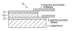
FIG. 1 is an explanatory view showing a basic structure of a sheet type cell which is an object to be evaluated of an evaluation apparatus and an evaluation method according to embodiments. -
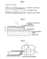
FIG. 2 is an explanatory view showing a sheet type cell to be evaluated attached with a positive electrode and a negative electrode. -
FIG. 3 is an explanatory view showing a case in which a conventional evaluation method of a conventional evaluation apparatus is applied to the sheet type cell ofFIG. 2 . -
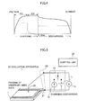
FIG. 4 is an explanatory view showing a general method for evaluating a charging/discharging characteristic of a sheet type cell. -
FIG. 5 is an explanatory view showing a schematic configuration of the evaluation apparatus according to the embodiments. -
FIG. 6 are explanatory views showing an evaluation method based on voltages of measuring two parts using a probe in the evaluation apparatus according to the embodiments. -
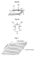
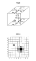
FIG. 7 is an explanatory view showing a manner of dividing an evaluated sheet type cell into imaginary elements. -
FIG. 8 is an explanatory view showing an equivalent circuit of the imaginary elements inFIG. 7 . -
FIG. 9 is an explanatory view showing the results of simulations in which the equivalent circuit ofFIG. 8 is applied to simulate a measured voltage of each element when there is a charge voltage defect. -
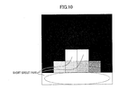
FIG. 10 is an explanatory view showing the measured voltage of each element in a prototype with a defect in internal resistance in a grayscale. -
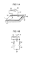
FIG. 11 are explanatory views showing an evaluation method based on an electric current flowing between two probes in the evaluation apparatus according to the embodiments. -
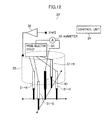
FIG. 12 is an explanatory view showing an evaluation apparatus which is a variation ofFIG. 11 to detect a direction in which an electrical current flows. -
FIG. 13 is an explanatory view showing a method (1) for appropriately detecting a defected part from a plurality of voltage measurement parts in the evaluation apparatus according to the embodiments. -
FIG. 14 is an explanatory view showing a method (2) for appropriately detecting a defected part from a plurality of voltage measurement parts in the evaluation apparatus according to the embodiments. -
FIG. 15 is an explanatory view showing a method of using evaluation results of the evaluation apparatus according to the embodiments. -
FIG. 16 is an explanatory view showing a variant embodiment in which the evaluation apparatus according to the embodiments is extended to be multi-probe type. - (A) Main Embodiment
- An embodiment of an evaluation apparatus and an evaluation method of a sheet type cell according to the present invention is described below by referring to the attached drawings.
- (A-1) Explanation of a Sheet Type Cell which can be an Object to be Evaluated
-
FIG. 1 is an explanatory view showing a layer structure of a sheet type cell which is an object to be evaluated by an evaluation apparatus and an evaluation method according to the embodiment. - A sheet type cell to be evaluated is not limited to the one which is implemented as a secondary cell, but may be the one which is implemented as a primary cell. Hereinafter, explanation is given supposing that the sheet type cell is a secondary cell. Also, any sheet type (parallel plate type) cell may be an object to be evaluated. For example, as shown in
FIG. 1 , a solid statesheet type cell 1 in which astorage layer 2 having a function of storing electricity is sandwiched between layers of apositive electrode 4 and anegative electrode 3 may be an object to be evaluated. Furthermore, for example, a solid state lithium cell may also be an object to be evaluated. Also, a sheet type cell with a storage layer in which a photoexcited structural change is utilized may be an object to be evaluated, for example. Moreover, an object to be evaluated may adopt a structure in which a plurality of thesheet type cells 1 ofFIG. 1 are layered in series to increase charge voltage, or a structure in which a plurality of thesheet type cells 1 ofFIG. 1 are layered in parallel to increase charge capacity. - Hereinafter, a sheet type cell having a storage layer in which a photoexcited structural change is used (hereinafter also referred to as a quantum cell), which may be the object to be evaluated, is briefly described. The storage layer in the quantum cell is referred to as a charging layer, in view of its characteristics.
- The charging layer stores electrons with a charging operation, releases the charged electrons with a discharging operation, and keeps the electrons (storage of electricity) in a state without charging/discharging. The charging layer is formed by applying a technology of photoexcited structural change.
- The photoexcited structural change is a phenomenon (technology) found out by Akira Nakazawa, who is the inventor of International Patent application JP2006/322011. That is, Akira Nakazawa found out that, when effective excitation energy is applied to an insulation-coated translucent metal oxide which is a semiconductor having a band gap as same as or more than a predetermined number, a lot of energy levels with no electrons are generated in the band gap. The quantum cell is charged by capturing electrons in these energy levels, and discharged by releasing the captured electrons.
- In the quantum cell, the
positive electrode 4 includes an electrode main body layer and a p-type metal oxide semiconductor layer formed to be in contact with thecharging layer 2. The p-type metal oxide semiconductor layer is provided to prevent injection of electrons from the electrode main body layer to thecharging layer 2. - The electrode main body layers of the
negative electrode 3 and thepositive electrode 4 are simply required to be formed as conductive layers. - The
charging layer 2 is formed in a way where insulation-coated n-type metal oxide semiconductor particles adhere to thenegative electrode 3 in a thin film shape, and is transformed to be capable of storing electrons with a photoexcited structural change caused at the n-type metal oxide semiconductor by ultraviolet irradiation. - (A-2) Evaluation Methods for Sheet Type Cells to be Evaluated as an Extension of Prior Arts and their Problems
- As described above,
FIG. 1 shows a basic configuration of thesheet type cell 1 to be evaluated.FIG. 2 shows asecondary cell device 10, in which thesheet type cell 1 is provided on asubstrate 7 that is used as a support, and anegative electrode terminal 5 and apositive electrode terminal 6 are attached to thenegative electrode 3 and thepositive electrode 4 of thesheet type cell 1 respectively. - It is intended that the evaluation method and the evaluation apparatus according to this embodiment, which will be described in detail later, are mainly applied to inspection during a production process. The inspection can be conducted by the evaluation method and the evaluation apparatus according to this embodiment without attaching the
negative electrode terminal 5 and thepositive electrode terminal 6, and the inspection can also be conducted after attaching thenegative electrode terminal 5 and thepositive electrode terminal 6. - It may be possible to conduct inspection for detecting a charging/discharging characteristic of the
secondary cell device 10, to which thenegative electrode terminals 5 and thepositive electrode terminal 6 are attached, similarly to the inspection of other secondary cells. - For example, as shown in
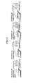
FIG. 3 , a voltage source (or a current source) 11 for supplying a charge current and acurrent source 12 for extracting a discharge current are allowed to be connected alternatively between thepositive electrode terminal 6 and thenegative electrode terminal 5 via aswitch 13, and a voltage meter (a digital voltage meter (DVM), for example) 14 for detecting a voltage between the terminals during the charging and the discharging is provided. It is to be noted that an ammeter for detecting the charge current or an ammeter for detecting the discharge current may be provided separately. Then, a charging time CC+CV (where CC is a charging time with constant current charging and CV is a charging time with constant voltage charging) that is shown inFIG. 4 , for example, and that is needed from a non-charged state until a fully charged state, and a discharging time that is needed from the fully charged state until the non-charged state are measured by the inspection, so as to evaluate the secondary cell device 10 (that is, the sheet type cell 1). - The secondary cell device 10 (that is, the sheet type cell 1) has a layer structure, and is practically formed in a plate shape. When there is an abnormality in the charging/discharging characteristics in such a layer structure, it is necessary to disassemble (or break) the
sheet type cell 1 as the object, so as to analyze and examine its inner part unless its cause appears on the surface or on the outer part. When the defect is in the inner part, the inner part can be hardly examined optically, unless the electrode is transparent, and special means using X-rays, β-rays or the like is required in order to examine the inner part nondestructively. In other words, it is difficult to identify the abnormal part, and the special means and the like are required for the identification. - The evaluation apparatus and the evaluation method according to this embodiment are made in view of the above-described circumstances.
- (A-3) Evaluation According to this Embodiment
- The evaluation method according to this embodiment is to measure an electric characteristic value (a voltage, for example) by bringing the probe into contact with an arbitrary part on the surface of the
positive electrode 4 of thesheet type cell 1, and to identify the abnormal part from the measurement result, if there is the abnormality such as the defect. A requirement for this embodiment is to probe the surface of thepositive electrode 4, and this embodiment is applicable when probing can be made on the arbitrary part on thepositive electrode 4 of thesheet type cell 1. Here, the probing means that the probe is electrically brought into contact with a contact part. - Hereinafter, an explanation will be given to the case where the evaluation is made by bringing the probe into contact with the arbitrary part on the surface of the
positive electrode 4 of thesheet type cell 1 and measuring the electric characteristic value. However, when the surface of thenegative electrode 3 of thesheet type cell 1 is exposed to the outside, such as when thesheet type cell 1 is removed from the substrate, the evaluation may be made by bringing the probe into contact with an arbitrary part on the surface of thenegative electrode 3 and measuring the electric characteristic value, or the evaluation may be made by bringing the probe into contact with the arbitrary parts on the surfaces of thepositive electrode 4 and thenegative electrode 3 and measuring the electric characteristic value. -
FIG. 5 is an explanatory view showing the configuration of an essential part of the evaluation apparatus according to this embodiment, and the same or corresponding numerals and symbols will be used to designate the same or corresponding components as those inFIG. 3 . The sheet type cell inspected by the evaluation apparatus according to this embodiment may be the one with the positive electrode terminal and the negative electrode terminal attached, or the one without the positive electrode terminal and the negative electrode terminal attached. Thesheet type cell 1 as shown inFIG. 5 is the one without the positive electrode terminal and the negative electrode terminal attached. - In addition to the voltage source (or the current source) 11, the
current source 12, theswitch 13, and thevoltage meter 14 that are described above, an evaluation apparatus 20 according to this embodiment includes afirst probe 21 that is brought into contact with thenegative electrode 3, asecond probe 22 that is brought into contact with the arbitrary part on thepositive electrode 4, aprobe moving mechanism 23 that moves theprobes voltage source 11, current extraction by thecurrent source 12, switching of theswitch 13, acquisition of a measurement value from thevoltage meter 14, movement control of theprobe moving mechanism 23, and the like. - It is to be noted that the
negative electrode 3 has an area where astorage layer 2 and the like are not provided thereon so as to enable the connection of the negative electrode terminal, for example (refer toFIG. 2 ), and thefirst probe 21 is capable of being brought into contact with that area. When thesheet type cell 1 to be evaluated is not attached to thesubstrate 7, thefirst probe 21 may also be capable of being brought into contact with the arbitrary part on thenegative electrode 3. - Although
FIG. 5 shows the one that is provided with only onesecond probe 22 to be connected to thepositive electrode 4, an installation method of the probe for selectively forming a charging path or a discharging path to/from a plurality of parts on thepositive electrode 4 is not limited to the one shown inFIG. 5 . For example, a plurality of second probes that are connected to different parts on thepositive electrode 4 may be provided, and one probe may be selected out of the plurality of probes so as to form the charging path or the discharging path. This variant embodiment will be described in detail in “Other embodiments” that will be described later. - In the inspection of the charging/discharging characteristic, the
control unit 24 first allows the voltage source (or the current source) 11 to be connected to thenegative electrode 3 and thepositive electrode 4 via theswitch 13, and allows the time to pass so that a voltage between both ends becomes constant, so as to attain the fully charged state. Then, in this state, thecontrol unit 24 allows theswitch 13 to be connected to thecurrent source 12, causes the discharging by allowing a current to flow in the direction opposite to the direction during the charging, and at the same time, measures the voltage between both ends. In other words, the charging/discharging characteristic can be inspected similarly to the conventional cases. For example, the charging time from the non-charged state until the fully charged state and the discharging time from the fully charged state to the non-charged state are measured by the inspection, so as to evaluate thesheet type cell 1. The evaluation may be made by an evaluator. Instead, the evaluation of the charging/discharging characteristic may be made by thecontrol unit 24 by determining whether the measured charging time is within a previously-set normal range or not, and determining whether the measured discharging time is within a previously-set normal range or not. - The inspection of the charging/discharging characteristic may be made on only one spot (gravity center of a contour, for example) that is arbitrarily selected on the
positive electrode 4, or may be made respectively on a plurality of spots on thepositive electrode 4. In the latter case, thesheet type cell 1 to be evaluated may be determined as normal when all the spots are evaluated as normal. - The evaluation configuration as shown in
FIG. 5 may be applied to identify the abnormal part.FIG. 6 are explanatory views of a principle of identifying the abnormal part. Here, the evaluation for identifying the abnormal part may be made when the evaluation result of the charging/discharging characteristic is no good, or may be made irrespective of the evaluation result of the charging/discharging characteristic. - As shown in
FIG. 6(A) , when theswitch 13 is opened after the charging and the voltage is measured at arbitrary two spots of m1 and m2 on thepositive electrode 4 with no load, voltages Vm1 and Vm2 that are different from each other are measured unless thesheet type cell 1 operates ideally.FIG. 6(B) shows an equivalent circuit of thesheet type cell 1 when the probing is made at the two spots. The voltages of the arbitrary spots m1 and m2 are represented by charged voltages V1 and V2 (which may be also referred to as electromotive voltages; but the electromotive voltages change over time due to the discharging and the like) when thesheet type cell 1 side (thenegative electrode 3 side) is seen from the spots m1 and m2, and internal resistances R1 and R2. The measurement voltage Vm1 at the spot m1 inFIGS. 6 is represented by the electromotive voltage V1 and the internal resistance R1 and is divided via an equivalent resistance Rc on thepositive electrode 4, as in expression (1). The measurement voltage Vm2 at the spot m2 is represented by the electromotive voltage V2 and the internal resistance R2 and is divided via the equivalent resistance Rc on thepositive electrode 4, as in expression (2). It is to be noted that a resistance value of thenegative electrode 3 is sufficiently small as compared with a resistance value of thepositive electrode 4 and the internal resistance, and is approximated as being ignorable, for the sake of simplicity. -
Vm1={(Rc+R2)×V1+R1×V2}/(R1+Rc+R2) (1) -
Vm2={(Rc+R1)×V2+R2×V1}/(R1+Rc+R2) (2) - The charge voltage measurement operation at the two spots, as described above, makes it possible to find out the characteristics and the abnormality of the electromotive voltages and the internal resistances at the measurement spots. When, for example, the respective layers of the
sheet type cell 1 are formed normally and uniformly, the measurement voltages Vm1 and Vm2 at the arbitrary two spots m1 and m2 are almost equal to each other, and have the values according to the equivalent resistance Rc at the stable time, as is clear from the expression (1) and the expression (2). Thepositive electrode 4 is usually formed by a uniform metal film and the equivalent resistance Rc is stable. However, when there is a crack or the like between the measurement spots m1 and m2, for example, the value of the equivalent resistance Rc is increased equivalently, which causes abnormal values in the measurement voltages Vm1 and Vm2. In addition, when thecharging layer 2 is generated differently between the arbitrary two spots m1 and m2, and when the electromotive voltages V1 and V2 are significantly different from each other, a significant difference is also caused between the measurement voltages Vm1 and Vm2. It is to be noted that, when the sheet type cell is in a completely broken state (dead state), the measurement voltages Vm1 and Vm2 become zero equally (the measurement voltages Vm1 and Vm2 become equal to each other). - It is to be noted that when the expression (1) and the expression (2) can be rearranged with respect to the electromotive voltages V1 and V2, and the rearranged expressions are applied, it is clear that the electromotive voltages V1 and V2 can be calculated from the measurement voltages Vm1 and Vm2 at the two spots. This means that the states of the charge voltages V1 and V2 can be figured out from the measurement voltages Vm1 and Vm2.
- Here, when the
substrate 7 is not provided on thenegative electrode 3 side, and when electrical probing is made similarly to thepositive electrode 4, the principle of operation similar to the above can also be applied (refer toFIG. 8 as will be described later). - When the evaluation of the charging/discharging characteristic at each of the arbitrary spots, and the evaluation based on the relationship of the measurement voltages of the electromotive voltages (charge voltages) at the plurality of spots, as described above, are made at the multiple spots, it is possible to perform the characteristic evaluation and the abnormality detection over the entire surface of the
sheet type cell 1. This embodiment aims at the multi-spot inspection as described above. - Hereinafter, it is demonstrated from a simulation result that the evaluation of the
sheet type cell 1 can be made from the measurement voltages (Vm1 and Vm2) at the arbitrary parts, with reference toFIG. 7 toFIG. 9 . - It is assumed that the
sheet type cell 1 to be evaluated is equally divided into N-pieces in the vertical direction and is equally divided into M-pieces in the horizontal direction, as shown inFIG. 7 , so as to obtain elements having the total number of N×M with the same configuration. In other words, it is assumed that the N×M elements having the same configuration are combined to form thesheet type cell 1 to be evaluated. Moreover, it is assumed that the centers of thepositive electrode 4 and thenegative electrode 3 of each of the elements are the parts where the probes are brought into contact therewith. Under such assumptions, the equivalent circuit of each of the elements can be shown asFIG. 8 . - In
FIG. 8 , VBS and RBS represent the electromotive voltage (charge voltage) and the internal resistance of the element, respectively. RCU and RCB represent resistance components of the positive electrode on the far side and on the near side from the center of thepositive electrode 4 in the vertical direction, respectively, and RCL and RCR represent resistance components of the positive electrode on the left side and on the right side from the center of thepositive electrode 4 in the horizontal direction, respectively. In addition, RBU and RBB represent resistance components of the negative electrode on the far side and on the near side from the center of thenegative electrode 3 in the vertical direction, respectively, and RBL and RBR represent resistance components of the negative electrode on the left side and on the right side from the center of thenegative electrode 3 in the horizontal direction, respectively. - By applying the equivalent circuit (circuit model) of the element as described above, the simulation for identifying the abnormal part in the
sheet type cell 1 is performed. -
FIG. 9 shows the result of the simulation about how the measurement voltage of thepositive electrode 4 of each of the elements will be, when there is a defect in thesheet type cell 1.FIG. 9 shows the case where thesheet type cell 1 is a quantum cell, and thesheet type cell 1, having the length L being 36 mm in the vertical direction and the length W being 37 mm in the horizontal direction, is divided into 9 pieces both in the vertical direction and in the horizontal direction. Further,FIG. 9 shows the case where thenegative electrode 3 is made of copper and has the thickness of its layer being 0.3 μm, and thepositive electrode 4 is made of copper and has the thickness of its layer being 0.3 μm. Furthermore, it shows the case where the internal resistance RBS of the storage layer (charging layer) 2 in each of the elements is 81 Ω (the internal resistance of thestorage layer 2 as a whole is 1 Ω as the internal resistances being 81 pieces in total are connected in parallel), and the charge voltage VBS of thestorage layer 2 in each of the elements is 2.0 V (ideal value). It is to be noted that it shows the case where the charge voltage VBS of the element that is the sixth in the X direction (horizontal direction) and the fourth in the Y direction (vertical direction) is 0 V (large defect), and the charge voltage VBS of the element that is the third in the X direction (horizontal direction) and the sixth in the Y direction (vertical direction) is 1 V (small defect). -
FIG. 9 shows the result of calculation of the voltages of the respective elements on the upper surface of thepositive electrode 4, under the assumptions as described above, with greyscale range equal to 1 mV (white to black). The voltage drops at the part (element) where the large defect or the small defect exists, and the voltages on the periphery follow the voltage of the defected part. Thus, the calculation result according to the principle of operation as explained with reference toFIGS. 6 is obtained. The voltage of the calculation result corresponds to the measurement voltage at a predetermined spot in the evaluation apparatus. Namely, the voltage at the predetermined spot is measured by bringing the probe into contact therewith, and the abnormal part can be identified from a difference between the measurement voltage and the ideal value, and a measurement voltage distribution. - The above description focuses on the charge voltage VBS and explains the calculation result when there is no abnormality in the internal resistances RBS of the respective elements of the
storage layer 2. As is clear from the above-described expression (1) and the expression (2), when the internal resistances RBS of the respective elements of the storage layer 2 (corresponding to R1 and R2 in the respective expressions) have the abnormality, it affects the voltage (measurement voltage) on the upper surface of the respective elements of thepositive electrode 4, similarly to the above. - An actual prototype of the quantum cell having the size of 30 mm×30 mm is used as the
sheet type cell 1, divided lengthwise and widthwise into 6×6 pieces, and subjected to the voltage measurement. As this prototype has a fault of a dead short circuit (internal resistance is 0 Ω) and has a small power capacity, the voltage is measured by giving a voltage of about 1 V from the outside and probing the respective elements.FIG. 10 shows differences between an average value of the measurement voltages at the 36 parts and the measurement values of the respective elements in a greyscale. When comparing it with the actual prototype, it is found out that there is good correspondence between the part where the measurement voltage is low and an area where the short circuit is considered to be caused (an area surrounded by a broken line). - In addition, when a distance and an electric potential difference between the measured two spots are made clear, it is possible to calculate a current flowing therebetween.
- Methods exemplified below may be adopted as an output method of the inspection result according to the evaluation apparatus of this embodiment, for example.
- The measurement value and a measurement process value (a difference from the average value of the measurement values, for example) for each of the elements are displayed or printed out as it is. The measurement value and the measurement process value for each of the elements are converted into scales where the measurement value and the measurement process value belong, so as to obtain a greyscale image as those displayed in
FIG. 9 andFIG. 10 , and the greyscale image is displayed or printed out. The measurement value and the measurement process value for each of the elements are compared with threshold values or the like, so as to obtain a binary image representing the normality and the abnormality, and the binary image is displayed or printed out. - (A-4) Effect of Embodiment
- According to the above-described embodiment, the evaluation is made by bringing the probe into contact with the positive electrode and by measuring the quantity of electricity. Accordingly, it is possible to easily evaluate the sheet type cell to be evaluated without destruction, and to identify the abnormal part, if any.
- (B) Other embodiments
- (B-1) According to the above-described embodiment, the explanation is given to the case where the evaluation is made by measuring the voltage at the arbitrary two spots on the
sheet type cell 1 to be evaluated (refer toFIG. 6 ). Instead of this case, or in addition to this case, the evaluation may be made by connecting an ammeter to the arbitrary two spots on thesheet type cell 1 to be evaluated. -
FIG. 11(A) is an explanatory view showing a connection method of the ammeter. Twoprobes positive electrode 4 of thesheet type cell 1. Base end sides of theprobes FIG. 11(B) . It is to be noted that V1, V2, R1, R2 and Rc inFIG. 11(B) are the same as those shown inFIG. 6(B) , respectively. A current value Im flowing through theammeter 32 is represented by the expression (3). -
Im={Rc//Ri/(R1+Rc//Ri+R2)}×{(V1−V2)/Ri} (3) -
where Rc//Ri=Rc×Ri/(Rc+Ri) - When the internal resistance value Ri of the
ammeter 32 is known, the measurement current value Im, the internal resistances R1 and R2, and the electromotive voltages (charge voltages) V1 and V2 at the respective spots m1 and m2 are associated with each other, as represented in the expression (3). In other words, a characteristic test and internal inspection are made possible by measuring the voltage. Particularly, when the highly sensitive ammeter, such as a galvanometer, is applied, it is possible to accurately find out the direction of a current flowing on the surface of thepositive electrode 4. - (B-2)
FIG. 12 shows a schematic configuration of anevaluation apparatus 33 that focuses on the direction of a current and facilitates the detection of the defect and the abnormality. Here, the same numerals and symbols will be used to designate the same or corresponding components as those inFIG. 11 . - The
probe 30 is brought into contact with the measurement part, and probes 31-N, 31-E, 31-S, and 31-W are respectively brought into contact with spots in four directions, each having an equal distance from the contact spot of theprobe 30 as the center. Base ends of the probes 31-N, 31-E, 31-S, and 31-W are connected to aprobe selection circuit 34. Theprobe selection circuit 34 selects only one probe out of the probes 31-N, 31-E, 31-S, and 31-W under the control of thecontrol unit 24. One end of the ammeter (galvanometer, for example) 32 is connected to a base end of theprobe 30, and the other end of theammeter 32 is connected to a common terminal of theprobe selection circuit 34. Thecontrol unit 24 allows the probes 31-N, 31-E, 31-S, and 31-W to be selected alternatively and cyclically, so as to measure a current flowing between theprobe 30 and any of the surrounding probes 31-N, 31-E, 31-S, and 31-W and, from the current measurement value, to find out the direction of a current flowing through the spot of thecenter probe 30 in the most probable manner. - In order to prevent an error current value from entering the current measurement value due to a difference between an electric potential of each of the
probes 30, 31-N, 31-E, 31-S, and 31-W and an electric potential of a surrounding member or the like, it is desirable that a predetermined electric potential Vref2 (an ideal electric potential that theprobe 30 may have, for example) is applied to a surroundingmember 35 or the like of theprobes 30, 31-N, 31-E, 31-S, and 31-W via abuffer amplifier 36 or the like, so as to prevent the current (error current) due to the difference with the electric potential of the surroundingmember 35, which should not be measured, from flowing to theammeter 32. In other words, it is desirable to perform guarding. - It is also possible to enhance spatial resolution further by increasing the number of the directions than that of the configuration of
FIG. 12 . - (B-3) According to the explanation of the principle of the evaluation operation of the above-described embodiment, the explanation is given to the voltage measurement after the charging (refer to
FIG. 6 ). With the actual sheet type cell (the quantum cell in this case) 1, the electromotive voltages at the respective parts converge to the lowest electromotive voltage over time after the charging (electromotive voltage uniformity). This is because, as many different electromotive voltages exist inside thesheet type cell 1, a current flows from the higher voltage to the lower voltage, and the discharging is caused inside until the voltages become the lowest voltage. In order to perform measurement at a plurality of spots with a limited number of probes, “full charge→the measurement at the spot A→the full charge→the measurement at the spot B . . . ” may be repeated as shown inFIG. 13 . That is, the measurement should be always made immediately after the full charge while internal mutual discharging as described above does not proceed. The charging between the measurements does not take much time as the charging is not performed from an empty state, and therefore the measurement time is not increased aimlessly even though the charging for making the fully charged state is performed before the measurement. - (B-4) Such inconvenience that the original difference in the voltages at the respective measurement parts is difficult to be detected as the electromotive voltages become uniform over time may be avoided by the voltage measurement with a load connected, instead of the voltage measurement immediately after the full charge as described above. Namely, when a known load (a current source or a constant resistance) 40 is connected to the
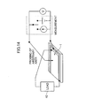
sheet type cell 1, as shown inFIG. 14 , the discharging to theexternal load 40 starts, and the balanced state inside thesheet type cell 1 collapses, even after the electromotive voltages temporarily converge to the lowest electromotive voltage due to the internal discharge. When the voltage is measured by probing the arbitrary spot, it is possible to detect the difference between the voltages at the respective measurement parts, similarly to the above-described measurement immediately after the full charge. - (B-5) Moreover, as it is possible to find out the part in the
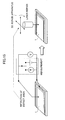
sheet type cell 1 where the measured voltage is abnormal (the defect, for example) by the moving function of the probe or thesheet type cell 1, or by the multi-probe, automatic detection and automatic repair are possible by inputting its location information (identification information of the defect may be added thereto) into a repair apparatus (a laser repair device, for example) 50 (FIG. 15 ). For example, when a short circuit is caused between thenegative electrode 3 and thepositive electrode 4 by a local foreign matter, that part is inactivated by the laser. Then, although the electromotive voltage at that part is lost and its power density is slightly reduced, the cell as a whole is protected. As a result, it is possible to improve a yield as a whole. - (B-6)
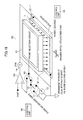
FIG. 16 shows an embodiment of an evaluation apparatus to which a multi-probe for measuring voltages at arbitrary parts is applied. Here, the same or corresponding numerals and symbols will be used to designate the same or corresponding components as those inFIG. 5 . - In an
evaluation apparatus 60 as shown inFIG. 16 , a plurality of probes 21-1 to 21-T are arranged at equal intervals lengthwise and widthwise. Base ends of the plurality of probes 21-1 to 21-T with tip ends thereof brought into contact with different parts on thepositive electrode 4 of thesheet type cell 1 are connected to aprobe selection circuit 61. It is to be noted that thenegative electrode 3 of thesheet type cell 1 is set to have a fixed electric potential (grounding, for example). Theprobe selection circuit 61 is formed by many switches and the like, and selects one probe 21-t, all the probes 21-1 to 21-T, or the probes that are functioning at that moment under the control of thecontrol unit 24. A common input and output terminal of theprobe selection circuit 61 is connected to a common terminal of theswitch 13 via aswitch 62. Similarly to the case inFIG. 5 , theswitch 13 selects the voltage source (or the current source) 11 or thecurrent source 12. When thevoltage source 11 is selected, the charging to thesheet type cell 1 is made. When thecurrent source 12 is selected, the discharging from thesheet type cell 1 is made. Theswitch 62 selects theswitch 13 or adifference circuit 63 under the control of thecontrol unit 24. Thedifference circuit 63 subtracts a predetermined voltage Vref1 from a pickup voltage of any probe 21-t that is given via theswitch 62, and the voltage after the subtraction is measured by the voltage meter (DVM) 14. - The voltage after subtracting the predetermined voltage Vref1 is measured in order to use a dynamic range of the
voltage meter 14 effectively and to improve measurement resolution. When the voltage is measured at the plurality of parts, calibration may be made at the respective parts by the predetermined voltage Vref1, so as to minimize an error due to a positional difference between the measurement parts. - Although not shown in
FIG. 16 , a mounting body of the probes 21-1 to 21-T or a mechanism to move a stage on which thesheet type cell 1 to be measured is mounted can realize the spatial resolution that is smaller than a pitch between the probes and improve throughput of the inspection. - In the example of
FIG. 16 , the probing of the arbitrary spot on thenegative electrode 3 is not made, and thenegative electrode 3 is fixedly and stably connected to the evaluation apparatus. However, the probing on the arbitrary spot on thenegative electrode 3 side may also be made. - In the example of
FIG. 16 , one probe 21-t is selected from a group of probes 21-1 to 21-T and the voltage of the probe 21-t is measured. However, in order to improve the throughput, a plurality of thedifference circuits 63 and the voltage meters (DVM) 14 may be provided so that the picked-up voltages of the plurality of probes are measured in parallel. - (B-7) The evaluation configuration based on the voltage measurement as shown in
FIG. 16 and the evaluation configuration based on the current measurement as shown inFIG. 12 may be combined to form one evaluation apparatus. - For example, the voltage (electric potential) may be measured at many parts by using the multi-probe, and the current measurement that can identify the direction and the like may be applied to the part where the measurement electric potential is determined to be abnormal, so as to search for the abnormal part with higher accuracy.
- (B-8) In the above-described embodiment, the explanation is given to the case where the
sheet type cell 1 functioning as a secondary cell having the configuration as shown inFIG. 1 is evaluated. The above-described evaluation method and evaluation apparatus may be applied even when the cell having the configuration as shown inFIG. 1 is applied as a primary cell.
Claims (20)
1. An evaluation method of a sheet type cell for evaluating the sheet type cell in which a storage layer is sandwiched by layers of a positive electrode and a negative electrode, the evaluation method comprising the step of
bringing an electrode probe into contact with a measurement part on an outer surface of at least one of the positive electrode and the negative electrode, and measuring quantity of electricity at the measurement part, so as to evaluate the sheet type cell.
2. The evaluation method of the sheet type cell according to claim 1 ,
wherein the electrode probe is brought into contact with the outer surface of one of the positive electrode and the negative electrode, and a fixed electric potential is applied to the entire electrode of the other of the positive electrode and the negative electrode.
3. The evaluation method of the sheet type cell according to claim 2 ,
wherein a charge source and a voltage meter are connected to the electrode probe, and a charge characteristic that changes the sheet type cell from a non-charged state to a fully charged state is detected from a change in a measurement voltage of the voltage meter, so as to evaluate the sheet type cell.
4. The evaluation method of the sheet type cell according to claim 2 ,
wherein a discharge source and a voltage meter are connected to the electrode probe, and a discharge characteristic that changes the sheet type cell from a fully charged state to a non-charged state is detected from a change in a measurement voltage of the voltage meter, so as to evaluate the sheet type cell.
5. The evaluation method of the sheet type cell according to claim 2 ,
wherein a charge source and a voltage meter are connected to the electrode probe, and a measurement voltage of the voltage meter is detected when the sheet type cell is in a fully charged state, so as to evaluate the sheet type cell.
6. The evaluation method of the sheet type cell according to claim 2 ,
wherein two or more of the electrode probes for the different measurement parts are provided, a discharge source and a voltage meter that are provided for each of the electrode probes are used, or the discharge source and the voltage meter that are common to the respective electrode probes and are connected, by switching, to each of the electrode probes are used, and a voltage after the charging is measured at the respective measurement parts via the respective electrode probes, so as to evaluate the sheet type cell based on magnitude of two or more measurement voltages.
7. The evaluation method of the sheet type cell according to claim 2 ,
wherein the two electrode probes for the different measurement parts are provided, and a current flowing between the two electrode probes is measured by an ammeter, so as to evaluate the sheet type cell based on a measurement current.
8. The evaluation method of the sheet type cell according to claim 1 ,
wherein the measurement part can be changed by movement of at least one of the electrode probe and the sheet type cell, and the quantity of electricity is measured at a plurality of the measurement parts, so as to make an evaluation.
9. The evaluation method of the sheet type cell according to claim 1 ,
wherein a plurality of the electrode probes that are brought into contact with the outer surface of the positive electrode or the negative electrode, and a probe selection circuit that selects the plurality of the electrode probes to form a circuit element of a measurement circuit are provided, and
wherein the selected electrode probes measure the quantity of electricity at a plurality of the measurement parts, so as to make an evaluation.
10. The evaluation method of the sheet type cell according to claim 8 ,
wherein measurement results and evaluation results at the plurality of the measurement parts are output collectively.
11. An evaluation apparatus of a sheet type cell for evaluating the sheet type cell in which a storage layer is sandwiched by layers of a positive electrode and a negative electrode, the evaluation apparatus comprising:
an electrode probe that is brought into contact with a measurement part on an outer surface of at least one of the positive electrode and the negative electrode; and
a measurement evaluation unit that measures quantity of electricity at the measurement part via the electrode probe, so as to evaluate the sheet type cell.
12. The evaluation apparatus of the sheet type cell according to claim 11 , wherein the electrode probe is brought into contact with the outer surface of one of the positive electrode and the negative electrode, and a fixed electric potential is applied to the entire electrode of the other of the positive electrode and the negative electrode.
13. The evaluation apparatus of the sheet type cell according to claim 12 , further comprising
a charge source connected to the electrode probe,
wherein the measurement evaluation unit detects a charge characteristic that changes the sheet type cell from a non-charged state to a fully charged state from a change in a measurement voltage of a voltage meter contained therein, so as to evaluate the sheet type cell.
14. The evaluation apparatus of the sheet type cell according to claim 12 , further comprising
a discharge source connected to the electrode probe,
wherein the measurement evaluation unit detects a discharge characteristic that changes the sheet type cell from a fully charged state to a non-charged state from a change in a measurement voltage of a voltage meter contained therein, so as to evaluate the sheet type cell.
15. The evaluation apparatus of the sheet type cell according to claim 12 , further comprising
a charge source connected to the electrode probe,
wherein the measurement evaluation unit detects a measurement voltage of a voltage meter contained therein when the sheet type cell is in a fully charged state, so as to evaluate the sheet type cell.
16. The evaluation apparatus of the sheet type cell according to claim 12 , further comprising
two or more of the electrode probes for the different measurement parts,
wherein the measurement evaluation unit uses a discharge source that is provided for each of the electrode probes and a voltage meter contained therein, or uses the discharge source that is common to the respective electrode probes and is connected, by switching, to each of the electrode probes and the voltage meter contained therein, and measures a voltage after the charging at the respective measurement parts via the respective electrode probes, so as to evaluate the sheet type cell based on magnitude of two or more measurement voltages.
17. The evaluation apparatus of the sheet type cell according to claim 12 , further comprising
the two electrode probes for the different measurement parts,
wherein the measurement evaluation unit measures a current flowing between the two electrode probes by an ammeter, so as to evaluate the sheet type cell based on a measurement current.
18. The evaluation apparatus of the sheet type cell according to claim 11 , further comprising
a relative movement mechanism that moves at least one of the electrode probe and the sheet type cell so as to allow the measurement part to change,
wherein the measurement evaluation unit measures the quantity of electricity at a plurality of the measurement parts, so as to make an evaluation.
19. The evaluation apparatus of the sheet type cell according to claim 11 , further comprising:
a plurality of the electrode probes that are brought into contact with the outer surface of the positive electrode or the negative electrode; and
a probe selection circuit that selects the plurality of the electrode probes to form a circuit element of a measurement circuit,
wherein the measurement evaluation unit selects the electrode probes and measures the quantity of electricity at a plurality of the measurement parts, so as to make an evaluation.
20. The evaluation apparatus of the sheet type cell according to claim 18 , further comprising
a collective output unit that collectively outputs measurement results and evaluation results at the plurality of the measurement parts.
Applications Claiming Priority (1)
| Application Number | Priority Date | Filing Date | Title |
|---|---|---|---|
| PCT/JP2011/070182 WO2013035149A1 (en) | 2011-09-05 | 2011-09-05 | Apparatus and method for evaluating sheet-like battery |
Publications (2)
| Publication Number | Publication Date |
|---|---|
| US20140327445A1 true US20140327445A1 (en) | 2014-11-06 |
| US10036780B2 US10036780B2 (en) | 2018-07-31 |
Family
ID=47831636
Family Applications (1)
| Application Number | Title | Priority Date | Filing Date |
|---|---|---|---|
| US14/342,870 Active 2032-09-15 US10036780B2 (en) | 2011-09-05 | 2011-09-05 | Evaluation apparatus and evaluation method of sheet type cell |
Country Status (8)
| Country | Link |
|---|---|
| US (1) | US10036780B2 (en) |
| EP (1) | EP2755274A4 (en) |
| JP (1) | JP5786028B2 (en) |
| KR (1) | KR101685461B1 (en) |
| CN (1) | CN103858271B (en) |
| CA (1) | CA2848164C (en) |
| TW (2) | TWI467202B (en) |
| WO (1) | WO2013035149A1 (en) |
Cited By (6)
| Publication number | Priority date | Publication date | Assignee | Title |
|---|---|---|---|---|
| US20150192611A1 (en) * | 2012-05-31 | 2015-07-09 | Guala Technology Co., Ltd. | Semiconductor probe, testing device and testing method for testing quantum battery |
| US20170131361A1 (en) * | 2014-07-31 | 2017-05-11 | Kabushiki Kaisha Nihon Micronics | Testing device and testing method for sheet-shaped cell |
| US20180210033A1 (en) * | 2015-07-22 | 2018-07-26 | Kabushiki Kaisha Nihon Micronics | Intermediate structure unit for secondary cell and method for manufacturing secondary cell |
| TWI648947B (en) * | 2017-09-01 | 2019-01-21 | 英穩達科技股份有限公司 | Apparatus and method for inspecting solar cell |
| US10367082B2 (en) | 2015-09-08 | 2019-07-30 | Kabushiki Kaisha Nihon Micronics | Secondary cell and method for manufacturing secondary cell |
| US11462777B2 (en) * | 2017-10-04 | 2022-10-04 | Envision Aesc Japan Ltd. | Battery pack inspection method and inspection device for anomaly detection via voltage comparison over time |
Families Citing this family (9)
| Publication number | Priority date | Publication date | Assignee | Title |
|---|---|---|---|---|
| CN106463677B (en) | 2014-05-27 | 2020-03-13 | 苹果公司 | Apparatus and method for reducing defective portion of battery |
| JP6266462B2 (en) * | 2014-07-31 | 2018-01-24 | 株式会社日本マイクロニクス | Sheet battery test apparatus and sheet battery test method |
| JP6358920B2 (en) * | 2014-10-20 | 2018-07-18 | 日置電機株式会社 | Contact state determination device, secondary battery inspection device, and contact state determination method |
| JP6753510B2 (en) * | 2017-03-03 | 2020-09-09 | 日産自動車株式会社 | Secondary battery and secondary battery control method |
| JP6791104B2 (en) * | 2017-11-29 | 2020-11-25 | トヨタ自動車株式会社 | Evaluation method of power storage device, manufacturing method of power storage device, and test system |
| KR102204699B1 (en) * | 2018-01-31 | 2021-01-18 | 주식회사 엘지화학 | Method and apparatus for evaluating safety of secondary battery |
| JP7275842B2 (en) * | 2019-05-16 | 2023-05-18 | トヨタ自動車株式会社 | BATTERY SYSTEM AND VEHICLE, AND BATTERY SYSTEM CONTROL METHOD |
| KR20210072313A (en) | 2019-12-09 | 2021-06-17 | 주식회사 엘지에너지솔루션 | Evaluation Method and Device for Dispersibility of Binder in Electrode Mixture Layer |
| CN217181168U (en) * | 2022-01-07 | 2022-08-12 | 宁德时代新能源科技股份有限公司 | Battery test assembly, battery assembly, charging assembly and electric equipment |
Citations (42)
| Publication number | Priority date | Publication date | Assignee | Title |
|---|---|---|---|---|
| US4702564A (en) * | 1985-04-15 | 1987-10-27 | Robert Parker | Battery tester including flexible substrate and polyacetilynic material |
| US5053995A (en) * | 1989-02-03 | 1991-10-01 | Olympus Optical Co., Ltd. | Tunnel current data storage apparatus having separate lever bodies |
| US5059895A (en) * | 1990-04-04 | 1991-10-22 | Eastman Kodak Company | Battery voltmeter |
| US5107206A (en) * | 1990-05-25 | 1992-04-21 | Tescon Co., Ltd. | Printed circuit board inspection apparatus |
| US5130658A (en) * | 1990-02-28 | 1992-07-14 | Display Matrix Corporation | Apparatus and method for indicating state of charge of a battery |
| US5483068A (en) * | 1994-01-07 | 1996-01-09 | Moulton; Russell D. | Use of IR (thermal) imaging for determining cell diagnostics |
| US5525890A (en) * | 1992-08-18 | 1996-06-11 | Sony Corporation | Battery unit and battery energy billing method |
| US5596278A (en) * | 1995-09-08 | 1997-01-21 | Duracell Inc. | Condition tester for a battery |
| US5681402A (en) * | 1994-11-04 | 1997-10-28 | Canon Kabushiki Kaisha | Photovoltaic element |
| US5903154A (en) * | 1997-04-08 | 1999-05-11 | Zhang; Chaojiong | Battery test contact assembly |
| US5966014A (en) * | 1997-10-17 | 1999-10-12 | Zhang; Chaojiong | System for simultaneously testing a plurality of batteries for multiple operating specifications |
| US6215311B1 (en) * | 1997-12-15 | 2001-04-10 | Sony Corporation | Battery cell inspecting method and apparatus |
| US20010032666A1 (en) * | 2000-03-24 | 2001-10-25 | Inegrated Power Solutions Inc. | Integrated capacitor-like battery and associated method |
| US20010046081A1 (en) * | 2000-01-31 | 2001-11-29 | Naoyuki Hayashi | Sheet-like display, sphere-like resin body, and micro-capsule |
| US20020180445A1 (en) * | 2000-09-14 | 2002-12-05 | Bertness Kevin I. | Method and apparatus for testing cells and batteries embedded in series/parallel systems |
| US6517967B1 (en) * | 1998-12-15 | 2003-02-11 | Electric Fuel Limited | Battery pack design for metal-air battery cells |
| US6569564B1 (en) * | 1995-02-22 | 2003-05-27 | Micron Technology, Inc. | Button cell constructions and thin profile battery constructions |
| US6611774B1 (en) * | 1998-08-19 | 2003-08-26 | Enersafe, Inc. | Method and apparatus for the continuous performance monitoring of a lead acid battery system |
| US20030215702A1 (en) * | 2002-05-08 | 2003-11-20 | Yuuji Tanjou | Secondary cell module and method of its production |
| US20040048113A1 (en) * | 2002-09-06 | 2004-03-11 | Murphy Michael W. | Method for detecting electrical defects in membrane electrode assemblies |
| US20040229111A1 (en) * | 2003-03-03 | 2004-11-18 | Pentax Corporation | Electronic device in which different types of bateries can be selectively used as a power source |
| US6828053B2 (en) * | 2002-07-26 | 2004-12-07 | General Motors Corporation | In-situ resistive current and temperature distribution circuit for a fuel cell |
| US20050074140A1 (en) * | 2000-08-31 | 2005-04-07 | Grasso Donald P. | Sensor and imaging system |
| US20060001430A1 (en) * | 2004-07-02 | 2006-01-05 | Kepler Keith D | Combinatorial method and apparatus for screening electrochemical materials |
| US20070026315A1 (en) * | 2004-12-28 | 2007-02-01 | Lampe-Onnerud Christina M | Lithium-ion secondary battery |
| US20070210760A1 (en) * | 2006-03-09 | 2007-09-13 | Nissan Motor Co., Ltd. | Battery, assembled battery unit, vehicle equipped with battery, and battery voltage adjusting method |
| US20070247116A1 (en) * | 2006-04-14 | 2007-10-25 | Nissan Motor Co., Ltd. | Capacity adjustment apparatus and method of secondary battery |
| US20070247117A1 (en) * | 2006-04-14 | 2007-10-25 | Nissan Motor Co., Ltd. | Capacity adjustment apparatus and method of secondary battery |
| US20080003492A1 (en) * | 2005-09-06 | 2008-01-03 | Oak Ridge Micro-Energy, Inc. | Long life thin film battery and method therefor |
| US20080238361A1 (en) * | 2007-03-26 | 2008-10-02 | Pinnell Leslie J | Adaptive charger device and method |
| US20090112099A1 (en) * | 2007-10-19 | 2009-04-30 | Panasonic Corporation | Ultrasonic probe, charger, ultrasonic diagnostic apparatus and ultrasonic diagnostic system |
| US7541817B2 (en) * | 2004-03-01 | 2009-06-02 | Metricorr Aps | Method and a system of diagnosing corrosion risk of a pipe or a pipeline in soil |
| US20090274958A1 (en) * | 2006-03-31 | 2009-11-05 | Mayumi Fukumine | Lithium-Ion Secondary Battery |
| US20100271036A1 (en) * | 2009-04-24 | 2010-10-28 | Sanyo Electric Co., Ltd. | Battery module, battery system and electric vehicle |
| US20110062915A1 (en) * | 2009-05-06 | 2011-03-17 | Lg Chem, Ltd. | Battery cell voltage balancing device |
| US20110084702A1 (en) * | 2009-10-14 | 2011-04-14 | Sony Corporation | Battery pack and method for detecting degradation of battery |
| US8004737B2 (en) * | 2006-11-02 | 2011-08-23 | Guala Technology Co., Ltd. | Electric-field-sensitive element and display device using the same |
| US8288046B2 (en) * | 2004-09-29 | 2012-10-16 | GM Global Technology Operations LLC | Integrated current sensors for a fuel cell stack |
| US20120288746A1 (en) * | 2010-01-19 | 2012-11-15 | Kiyoko Abe | Sheet-type secondary battery and method of manufacturing same |
| US20130207618A1 (en) * | 2010-07-15 | 2013-08-15 | Zpower, Llc | Method and apparatus for recharging a battery |
| US20150042289A1 (en) * | 2013-08-06 | 2015-02-12 | Denso Corporation | Assembled battery |
| US20150109019A1 (en) * | 2013-10-22 | 2015-04-23 | Semiconductor Energy Laboratory Co., Ltd. | Method for evaluating semiconductor device |
Family Cites Families (16)
| Publication number | Priority date | Publication date | Assignee | Title |
|---|---|---|---|---|
| JPH09288155A (en) * | 1996-04-23 | 1997-11-04 | Bell Techno:Kk | Battery checking method and battery checker |
| JP3364677B2 (en) * | 1998-07-14 | 2003-01-08 | ジャパンシステムエンジニアリング株式会社 | Rechargeable battery inspection device |
| JP3531866B2 (en) | 2000-07-28 | 2004-05-31 | 独立行政法人 科学技術振興機構 | Thin-film solid lithium ion secondary battery |
| JP2003215190A (en) * | 2001-11-16 | 2003-07-30 | Hioki Ee Corp | Short-circuit detector |
| JP4041313B2 (en) * | 2002-01-18 | 2008-01-30 | キヤノンマシナリー株式会社 | Battery inspection method and battery inspection apparatus |
| JP4986398B2 (en) * | 2002-07-01 | 2012-07-25 | アイゼンリンク、ロルフ | A new way to store electrical energy in so-called Quantum batteries |
| JP2006322011A (en) | 2006-07-31 | 2006-11-30 | Daikin Ind Ltd | Method of emulsion polymerization of tetrafluoroethylene |
| EP2137543B1 (en) | 2007-04-19 | 2012-02-08 | Oerlikon Solar AG, Trübbach | Test equipment for automated quality control of thin film solar modules |
| JP5323375B2 (en) * | 2008-03-25 | 2013-10-23 | 株式会社Kri | Voltage distribution evaluation method for power storage devices |
| WO2009123040A1 (en) | 2008-03-31 | 2009-10-08 | 株式会社アルバック | Solar cell manufacturing method, solar cell manufacturing device, and solar cell |
| US8049521B2 (en) | 2008-04-14 | 2011-11-01 | Applied Materials, Inc. | Solar parametric testing module and processes |
| US8877367B2 (en) * | 2009-01-16 | 2014-11-04 | The Board Of Trustees Of The Leland Stanford Junior University | High energy storage capacitor by embedding tunneling nano-structures |
| WO2010135321A2 (en) | 2009-05-19 | 2010-11-25 | Applied Materials, Inc. | Method and apparatus for solar cell production line control and process analysis |
| IT1395561B1 (en) * | 2009-09-03 | 2012-09-28 | Applied Materials Inc | TEST SYSTEM AND ITS PROCEDURE |
| JP5448914B2 (en) | 2010-02-22 | 2014-03-19 | 三菱重工業株式会社 | Secondary battery module diagnostic device |
| CN101853902B (en) * | 2010-06-11 | 2012-11-21 | 深圳市创益科技发展有限公司 | Equipment and method for eliminating defects of solar battery |
-
2011
- 2011-09-05 US US14/342,870 patent/US10036780B2/en active Active
- 2011-09-05 WO PCT/JP2011/070182 patent/WO2013035149A1/en active Application Filing
- 2011-09-05 KR KR1020147004981A patent/KR101685461B1/en active IP Right Grant
- 2011-09-05 CN CN201180073266.3A patent/CN103858271B/en active Active
- 2011-09-05 EP EP11871926.9A patent/EP2755274A4/en not_active Withdrawn
- 2011-09-05 CA CA2848164A patent/CA2848164C/en active Active
- 2011-09-05 JP JP2013532338A patent/JP5786028B2/en active Active
-
2012
- 2012-04-11 TW TW101112779A patent/TWI467202B/en active
- 2012-04-11 TW TW103119714A patent/TWI554770B/en active
Patent Citations (60)
| Publication number | Priority date | Publication date | Assignee | Title |
|---|---|---|---|---|
| US4702564A (en) * | 1985-04-15 | 1987-10-27 | Robert Parker | Battery tester including flexible substrate and polyacetilynic material |
| US5053995A (en) * | 1989-02-03 | 1991-10-01 | Olympus Optical Co., Ltd. | Tunnel current data storage apparatus having separate lever bodies |
| US5130658A (en) * | 1990-02-28 | 1992-07-14 | Display Matrix Corporation | Apparatus and method for indicating state of charge of a battery |
| US5059895A (en) * | 1990-04-04 | 1991-10-22 | Eastman Kodak Company | Battery voltmeter |
| US5107206A (en) * | 1990-05-25 | 1992-04-21 | Tescon Co., Ltd. | Printed circuit board inspection apparatus |
| US5525890A (en) * | 1992-08-18 | 1996-06-11 | Sony Corporation | Battery unit and battery energy billing method |
| US5483068A (en) * | 1994-01-07 | 1996-01-09 | Moulton; Russell D. | Use of IR (thermal) imaging for determining cell diagnostics |
| US6472594B1 (en) * | 1994-11-04 | 2002-10-29 | Canon Kabushiki Kaisha | Photovoltaic element and method for producing the same |
| US5681402A (en) * | 1994-11-04 | 1997-10-28 | Canon Kabushiki Kaisha | Photovoltaic element |
| US5861324A (en) * | 1994-11-04 | 1999-01-19 | Canon Kabushiki Kaisha | Method for producing photovoltaic element |
| US6569564B1 (en) * | 1995-02-22 | 2003-05-27 | Micron Technology, Inc. | Button cell constructions and thin profile battery constructions |
| US5596278A (en) * | 1995-09-08 | 1997-01-21 | Duracell Inc. | Condition tester for a battery |
| US5903154A (en) * | 1997-04-08 | 1999-05-11 | Zhang; Chaojiong | Battery test contact assembly |
| US5966014A (en) * | 1997-10-17 | 1999-10-12 | Zhang; Chaojiong | System for simultaneously testing a plurality of batteries for multiple operating specifications |
| US6215311B1 (en) * | 1997-12-15 | 2001-04-10 | Sony Corporation | Battery cell inspecting method and apparatus |
| US6611774B1 (en) * | 1998-08-19 | 2003-08-26 | Enersafe, Inc. | Method and apparatus for the continuous performance monitoring of a lead acid battery system |
| US6517967B1 (en) * | 1998-12-15 | 2003-02-11 | Electric Fuel Limited | Battery pack design for metal-air battery cells |
| US20010046081A1 (en) * | 2000-01-31 | 2001-11-29 | Naoyuki Hayashi | Sheet-like display, sphere-like resin body, and micro-capsule |
| US20010032666A1 (en) * | 2000-03-24 | 2001-10-25 | Inegrated Power Solutions Inc. | Integrated capacitor-like battery and associated method |
| US20050074140A1 (en) * | 2000-08-31 | 2005-04-07 | Grasso Donald P. | Sensor and imaging system |
| US20020180445A1 (en) * | 2000-09-14 | 2002-12-05 | Bertness Kevin I. | Method and apparatus for testing cells and batteries embedded in series/parallel systems |
| US6906523B2 (en) * | 2000-09-14 | 2005-06-14 | Midtronics, Inc. | Method and apparatus for testing cells and batteries embedded in series/parallel systems |
| US7504179B2 (en) * | 2002-05-08 | 2009-03-17 | Nissan Motor Co., Ltd. | Secondary cell module and method of its production |
| US20030215702A1 (en) * | 2002-05-08 | 2003-11-20 | Yuuji Tanjou | Secondary cell module and method of its production |
| US6828053B2 (en) * | 2002-07-26 | 2004-12-07 | General Motors Corporation | In-situ resistive current and temperature distribution circuit for a fuel cell |
| US20040048113A1 (en) * | 2002-09-06 | 2004-03-11 | Murphy Michael W. | Method for detecting electrical defects in membrane electrode assemblies |
| US7179553B2 (en) * | 2002-09-06 | 2007-02-20 | General Motors Corporation | Method for detecting electrical defects in membrane electrode assemblies |
| US20040229111A1 (en) * | 2003-03-03 | 2004-11-18 | Pentax Corporation | Electronic device in which different types of bateries can be selectively used as a power source |
| US7541817B2 (en) * | 2004-03-01 | 2009-06-02 | Metricorr Aps | Method and a system of diagnosing corrosion risk of a pipe or a pipeline in soil |
| US20060001430A1 (en) * | 2004-07-02 | 2006-01-05 | Kepler Keith D | Combinatorial method and apparatus for screening electrochemical materials |
| US7633267B2 (en) * | 2004-07-02 | 2009-12-15 | Farasis Energy, Inc. | Apparatus for combinatorial screening of electrochemical materials |
| US8288046B2 (en) * | 2004-09-29 | 2012-10-16 | GM Global Technology Operations LLC | Integrated current sensors for a fuel cell stack |
| US20110059349A1 (en) * | 2004-12-28 | 2011-03-10 | Boston-Power, Inc. | Lithium-ion secondary battery |
| US20070026315A1 (en) * | 2004-12-28 | 2007-02-01 | Lampe-Onnerud Christina M | Lithium-ion secondary battery |
| US20090181296A1 (en) * | 2004-12-28 | 2009-07-16 | Boston-Power, Inc. | Lithium-Ion secondary battery |
| US7811707B2 (en) * | 2004-12-28 | 2010-10-12 | Boston-Power, Inc. | Lithium-ion secondary battery |
| US7811708B2 (en) * | 2004-12-28 | 2010-10-12 | Boston-Power, Inc. | Lithium-ion secondary battery |
| US20080003492A1 (en) * | 2005-09-06 | 2008-01-03 | Oak Ridge Micro-Energy, Inc. | Long life thin film battery and method therefor |
| US20070210760A1 (en) * | 2006-03-09 | 2007-09-13 | Nissan Motor Co., Ltd. | Battery, assembled battery unit, vehicle equipped with battery, and battery voltage adjusting method |
| US8936872B2 (en) * | 2006-03-31 | 2015-01-20 | Zeon Corporation | Lithium-ion secondary battery |
| US20090274958A1 (en) * | 2006-03-31 | 2009-11-05 | Mayumi Fukumine | Lithium-Ion Secondary Battery |
| US20070247116A1 (en) * | 2006-04-14 | 2007-10-25 | Nissan Motor Co., Ltd. | Capacity adjustment apparatus and method of secondary battery |
| US7612533B2 (en) * | 2006-04-14 | 2009-11-03 | Nissan Motor Co., Ltd. | Capacity adjustment apparatus and method of secondary battery |
| US20070247117A1 (en) * | 2006-04-14 | 2007-10-25 | Nissan Motor Co., Ltd. | Capacity adjustment apparatus and method of secondary battery |
| US7612534B2 (en) * | 2006-04-14 | 2009-11-03 | Nissan Motor Co., Ltd. | Capacity adjustment apparatus and method of secondary battery |
| US8004737B2 (en) * | 2006-11-02 | 2011-08-23 | Guala Technology Co., Ltd. | Electric-field-sensitive element and display device using the same |
| US8587855B2 (en) * | 2006-11-02 | 2013-11-19 | Guala Technology Co., Ltd. | Electric-field-sensitive element and display device using the same |
| US20110300667A1 (en) * | 2006-11-02 | 2011-12-08 | Guala Technology | Electric-field-sensitive element and display device using the same |
| US20080238361A1 (en) * | 2007-03-26 | 2008-10-02 | Pinnell Leslie J | Adaptive charger device and method |
| US9013139B2 (en) * | 2007-03-26 | 2015-04-21 | The Gillette Company | Adaptive charger device and method |
| US20090112099A1 (en) * | 2007-10-19 | 2009-04-30 | Panasonic Corporation | Ultrasonic probe, charger, ultrasonic diagnostic apparatus and ultrasonic diagnostic system |
| US20100271036A1 (en) * | 2009-04-24 | 2010-10-28 | Sanyo Electric Co., Ltd. | Battery module, battery system and electric vehicle |
| US20110062915A1 (en) * | 2009-05-06 | 2011-03-17 | Lg Chem, Ltd. | Battery cell voltage balancing device |
| US20110084702A1 (en) * | 2009-10-14 | 2011-04-14 | Sony Corporation | Battery pack and method for detecting degradation of battery |
| US8487630B2 (en) * | 2009-10-14 | 2013-07-16 | Sony Corporation | Battery pack and method for detecting degradation of battery |
| US20120288746A1 (en) * | 2010-01-19 | 2012-11-15 | Kiyoko Abe | Sheet-type secondary battery and method of manufacturing same |
| US20130207618A1 (en) * | 2010-07-15 | 2013-08-15 | Zpower, Llc | Method and apparatus for recharging a battery |
| US9240696B2 (en) * | 2010-07-15 | 2016-01-19 | Zpower, Llc | Method and apparatus for recharging a battery |
| US20150042289A1 (en) * | 2013-08-06 | 2015-02-12 | Denso Corporation | Assembled battery |
| US20150109019A1 (en) * | 2013-10-22 | 2015-04-23 | Semiconductor Energy Laboratory Co., Ltd. | Method for evaluating semiconductor device |
Cited By (8)
| Publication number | Priority date | Publication date | Assignee | Title |
|---|---|---|---|---|
| US20150192611A1 (en) * | 2012-05-31 | 2015-07-09 | Guala Technology Co., Ltd. | Semiconductor probe, testing device and testing method for testing quantum battery |
| US9778284B2 (en) * | 2012-05-31 | 2017-10-03 | Kabushiki Kaisha Nihon Micronics | Semiconductor probe, testing device and testing method for testing quantum battery |
| US20170131361A1 (en) * | 2014-07-31 | 2017-05-11 | Kabushiki Kaisha Nihon Micronics | Testing device and testing method for sheet-shaped cell |
| US20180210033A1 (en) * | 2015-07-22 | 2018-07-26 | Kabushiki Kaisha Nihon Micronics | Intermediate structure unit for secondary cell and method for manufacturing secondary cell |
| US10705151B2 (en) * | 2015-07-22 | 2020-07-07 | Kabushiki Kaisha Nihon Micronics | Intermediate structure unit for secondary cell and method for manufacturing secondary cell |
| US10367082B2 (en) | 2015-09-08 | 2019-07-30 | Kabushiki Kaisha Nihon Micronics | Secondary cell and method for manufacturing secondary cell |
| TWI648947B (en) * | 2017-09-01 | 2019-01-21 | 英穩達科技股份有限公司 | Apparatus and method for inspecting solar cell |
| US11462777B2 (en) * | 2017-10-04 | 2022-10-04 | Envision Aesc Japan Ltd. | Battery pack inspection method and inspection device for anomaly detection via voltage comparison over time |
Also Published As
| Publication number | Publication date |
|---|---|
| CN103858271B (en) | 2016-08-17 |
| CN103858271A (en) | 2014-06-11 |
| CA2848164A1 (en) | 2013-03-14 |
| US10036780B2 (en) | 2018-07-31 |
| WO2013035149A1 (en) | 2013-03-14 |
| CA2848164C (en) | 2018-01-23 |
| KR20140044921A (en) | 2014-04-15 |
| KR101685461B1 (en) | 2016-12-20 |
| TW201435376A (en) | 2014-09-16 |
| JP5786028B2 (en) | 2015-09-30 |
| TWI554770B (en) | 2016-10-21 |
| JPWO2013035149A1 (en) | 2015-03-23 |
| EP2755274A1 (en) | 2014-07-16 |
| TWI467202B (en) | 2015-01-01 |
| TW201312139A (en) | 2013-03-16 |
| EP2755274A4 (en) | 2015-06-03 |
Similar Documents
| Publication | Publication Date | Title |
|---|---|---|
| US10036780B2 (en) | Evaluation apparatus and evaluation method of sheet type cell | |
| CN109387788B (en) | Method for inspecting electric storage device and method for manufacturing electric storage device | |
| KR102204699B1 (en) | Method and apparatus for evaluating safety of secondary battery | |
| WO2013065094A1 (en) | Device and method for testing of quantum cell by semiconductor probe | |
| CN105518473B (en) | The accurate detector of the charging current of charge and discharge device | |
| KR20200005290A (en) | Method of detecting electrode damage in pouch type secondary battery and apparatus for detecting electrode damage in pouch type secondary battery | |
| KR20190069596A (en) | System and method for evaluating electrochemical cell quality | |
| Wang et al. | In Situ Detection of Lithium‐Ion Battery Pack Capacity Inconsistency Using Magnetic Field Scanning Imaging | |
| Wang et al. | Evaluation of lithium-ion battery pack capacity consistency using one-dimensional magnetic field scanning | |
| JP6167917B2 (en) | Secondary battery inspection method and inspection device | |
| CN107884720A (en) | Detection method and detection means for battery modules leak inductance | |
| Ank et al. | Influence analysis of production defects of lithium-ion cells using single-cell and multi-cell characterization | |
| CN107728079B (en) | Quick detecting system of photovoltaic energy storage battery | |
| JP2007103112A (en) | Inspection method and inspection device of lead-acid battery | |
| KR101462108B1 (en) | A method for testing a measurement arrangement for voltage determination, and a method for charging a chargeable voltage source | |
| KR101398477B1 (en) | Precise Detector of Charge Voltage for Charge-Discharge Device | |
| WO2021044155A1 (en) | Battery characterisation and monitoring system | |
| JP7453203B2 (en) | Evaluation method of power storage device and manufacturing method of power storage device | |
| JP2017003325A (en) | Secondary battery inspection method | |
| KR20230033529A (en) | Battery cell Inspection system and method for measuring electrical characteristics of pouch-type battery cell | |
| Pettinger | Production test procedures | |
| KR20230058932A (en) | Electrode tap disconnection inspection device of battery cell | |
| WO2019096362A1 (en) | Device and method for testing a solid state elektrolyte and system | |
| KR20240007470A (en) | Apparatus for checking insulation of secondary battery | |
| KR20230081430A (en) | Method and apparatus for detecting defects of rechargeable battery |
Legal Events
| Date | Code | Title | Description |
|---|---|---|---|
| AS | Assignment |
Owner name: KABUSHIKI KAISHA NIHON MICRONICS, JAPAN Free format text: ASSIGNMENT OF ASSIGNORS INTEREST;ASSIGNORS:DEWA, HARUTADA;HIWADA, KIYOYASU;REEL/FRAME:032938/0698 Effective date: 20140508 |
|
| STCF | Information on status: patent grant |
Free format text: PATENTED CASE |
|
| MAFP | Maintenance fee payment |
Free format text: PAYMENT OF MAINTENANCE FEE, 4TH YEAR, LARGE ENTITY (ORIGINAL EVENT CODE: M1551); ENTITY STATUS OF PATENT OWNER: LARGE ENTITY Year of fee payment: 4 |