US20150017841A1 - Plug and receptacle of power connector - Google Patents
Plug and receptacle of power connector Download PDFInfo
- Publication number
- US20150017841A1 US20150017841A1 US13/938,353 US201313938353A US2015017841A1 US 20150017841 A1 US20150017841 A1 US 20150017841A1 US 201313938353 A US201313938353 A US 201313938353A US 2015017841 A1 US2015017841 A1 US 2015017841A1
- Authority
- US
- United States
- Prior art keywords
- receptacle
- plug
- bar
- trough
- terminals
- Prior art date
- Legal status (The legal status is an assumption and is not a legal conclusion. Google has not performed a legal analysis and makes no representation as to the accuracy of the status listed.)
- Granted
Links
Images


Classifications
-
- H—ELECTRICITY
- H01—ELECTRIC ELEMENTS
- H01R—ELECTRICALLY-CONDUCTIVE CONNECTIONS; STRUCTURAL ASSOCIATIONS OF A PLURALITY OF MUTUALLY-INSULATED ELECTRICAL CONNECTING ELEMENTS; COUPLING DEVICES; CURRENT COLLECTORS
- H01R13/00—Details of coupling devices of the kinds covered by groups H01R12/70 or H01R24/00 - H01R33/00
- H01R13/64—Means for preventing incorrect coupling
-
- H—ELECTRICITY
- H01—ELECTRIC ELEMENTS
- H01R—ELECTRICALLY-CONDUCTIVE CONNECTIONS; STRUCTURAL ASSOCIATIONS OF A PLURALITY OF MUTUALLY-INSULATED ELECTRICAL CONNECTING ELEMENTS; COUPLING DEVICES; CURRENT COLLECTORS
- H01R13/00—Details of coupling devices of the kinds covered by groups H01R12/70 or H01R24/00 - H01R33/00
- H01R13/62—Means for facilitating engagement or disengagement of coupling parts or for holding them in engagement
- H01R13/627—Snap or like fastening
- H01R13/6271—Latching means integral with the housing
- H01R13/6272—Latching means integral with the housing comprising a single latching arm
-
- H—ELECTRICITY
- H01—ELECTRIC ELEMENTS
- H01R—ELECTRICALLY-CONDUCTIVE CONNECTIONS; STRUCTURAL ASSOCIATIONS OF A PLURALITY OF MUTUALLY-INSULATED ELECTRICAL CONNECTING ELEMENTS; COUPLING DEVICES; CURRENT COLLECTORS
- H01R2107/00—Four or more poles
Definitions
- the invention relates to electric connectors, particularly to connectors for electric power.
- a conventional power connector is composed of a plug and a receptacle. Such a connection interface is symmetric and has no foolproof mechanism. Misconnection tends to occur because of users' or workers' errors. Misconnection may cause serious damage for hardware and/software.
- An object of the invention is to provide a power connector, which is provided with a misconnection-proof mechanism. This can prevent the connector from being erroneously connecting.
- the plug of the invention includes an insulative body having a first bar and a second bar at a space.
- the first bar is longitudinally formed with only one first channel for receiving a first plug terminal.
- the second bar is longitudinally formed with a plurality of second channels for receiving a plurality of second plug terminals.
- the receptacle of the invention includes an insulative seat having a first trough for connecting the first bar and a second trough for connecting the second bar.
- the first and second troughs are arranged at a space.
- the first trough is provided with only one first receptacle terminal.
- the second trough is provided with a plurality of second receptacle terminals which are parallel with each other and arranged at a space.
- the second bar cannot be inserted into the first trough.
- the plug and receptacle can be connected only in a correct direction.
- FIG. 1 is a perspective view of the plug and receptacle of the first embodiment of the invention
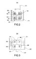
- FIG. 2 is a plan view of the plug of the first embodiment of the invention
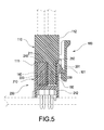
- FIG. 3 is a plan view of the receptacle of the first embodiment of the invention.
- FIG. 4 is a schematic view of the plug and receptacle of the first embodiment of the invention.
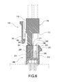
- FIG. 5 is another schematic view of the plug and receptacle of the first embodiment of the invention.
- FIG. 6 is a schematic view showing misconnection of the plug and receptacle of the first embodiment of the invention.
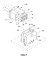
- FIG. 7 is a perspective view of the plug and receptacle of the second embodiment of the invention.
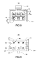
- FIG. 8 is a plan view of the plug of the second embodiment of the invention.
- FIG. 9 is a plan view of the receptacle of the second embodiment of the invention.
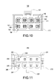
- FIG. 10 is a plan view of the plug of the third embodiment of the invention.
- FIG. 11 is a plan view of the receptacle of the third embodiment of the invention.
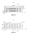
- FIG. 12 is a plan view of the plug of the fourth embodiment of the invention.
- FIG. 13 is a plan view of the receptacle of the fourth embodiment of the invention.
- the power connector 100 of the invention includes a plug 110 and a receptacle 200 .
- the plug 100 includes an insulative body 110 , two first plug terminals 120 and two second plug terminals 130 .
- the insulative body 110 is a substantial hexahedron, which is preferably made of plastic.
- the insulative body 110 has a body top 111 and four body sides 112 around the body top 111 .
- the body sides 112 perpendicularly connect to the body top 111 .
- Two first bars 140 and a second bar 150 are extended from the body top 111 .
- One of the body sides 112 is formed with a hooked rod 101 .
- the hooked rod 101 extends over the body top 111 .
- the first bars 140 and second bar 150 are arranged at a space.
- the first bars 140 are cuboids.
- Each of the first bars 140 is longitudinally formed with only one first channel 141 .
- the second bar 150 is a cuboid. A width of at least one edge of the second bar 150 is greater than a maximum width of an edge of the first bar 140 .
- the second bar 150 is longitudinally formed with two second troughs 151 .
- the two second troughs 151 are parallel with each other and arranged at a space.
- Two angles of each of the second bar 150 are separately formed with two second outer chamfers 152 .
- the first channels 141 and second troughs 151 are parallel.
- the first channels 141 are arranged in a row and the second troughs 151 are arrange in another row.
- the first and second plug terminals 120 , 130 are sleeves made of metal. Each of the first plug terminals 120 is received in one of the first channels 141 . Each of the second plug terminals 130 is received in one of the second troughs 151 .
- the receptacle 200 is used to connect the plug 100 and includes an insulative seat 210 , two first receptacle terminals 220 and two second receptacle terminals 230 .
- the insulative seat 210 is a substantial hexahedron, which is preferably made of plastic.
- the insulative seat 210 has a seat top 211 and four seat sides 212 around the seat top 211 .
- a first trough 240 for being inserted by the first bar 140 and a second trough 250 for being inserted by the second bar 150 are extended from the seat top 211 .
- One of the seat sides 212 is formed with a hooked protrusion 201 for engaging with the hooked rod 101 .
- the first and second troughs 240 , 250 are arranged at a space and correspond to the first and second bars 140 , 150 .
- each of the first troughs 240 are separately formed with two first inner chamfers 241 corresponding to the first outer chamfers 142 .
- Each of the second troughs 250 is longitudinally formed with two second troughs 151 .
- the two second troughs 151 are parallel with each other and arranged at a space.
- Two angles of each of the second troughs 150 are separately formed with two second inner chamfers 251 corresponding to the second outer chamfers 152 .
- the first receptacle terminals 220 are poles made of metal and have an outline corresponding to the first plug terminals 120 . Each of the first receptacle terminals 220 is received in one of the first troughs 240 .
- the second receptacle terminals 230 are poles made of metal and similar to the first receptacle terminals 220 in structure.
- the second receptacle terminals 230 are used to connect the second plug terminals 130 .
- the second receptacle terminals 230 are received in the second trough 250 .
- the second receptacle terminals 230 are parallel and arranged in a row.
- Each of the first receptacle terminals 220 passes through the bottom of the first trough 240 .
- Each of the second receptacle terminals 230 passes through the bottom of the second trough 250 .
- FIGS. 4 and 5 Please refer to FIGS. 4 and 5 .
- the first bars 140 and the second bar 150 are inserted into the first troughs 240 and the second trough 250 , respectively.
- the hooked rod 101 engages with the hooked protrusion 201 so that the plug 100 can firmly couple with the receptacle 200 .
- the second bar 150 cannot be inserted into the first trough 240 .
- the first bar 140 has the first outer chamfer 142 and the first trough 240 has the first inner chamfer 241 , the first bar 140 cannot be inserted into the first trough 240 .
- the invention allows the plug 100 and receptacle 200 to be coupled only in a correct direction.
- the insulative body 110 of the plug 100 has three first bars 140 and a second bar 150 .
- Each of the first bars 140 receives one of the first plug terminals 120 .
- the second bar 150 has three second channels 151 for separately receiving the three second plug terminals 130 .
- the first and second plug terminals 120 , 130 are separately arranged in two rows.
- the receptacle 200 corresponds to the plug 100 .
- the insulative seat 210 is formed with three first troughs 240 and a second trough 250 .
- Each of the first troughs 240 receives one of the first receptacle terminals 220 and the second trough 250 receives three first receptacle terminals 220 .
- the insulative body 110 of the plug 100 has four first bars 140 and two second bars 150 .
- Each of the first bars 140 receives one of the first plug terminals 120 .
- Each of the second bars 150 has two second channels 151 for separately receiving the two second plug terminals 130 .
- the first and second plug terminals 120 , 130 are separately arranged in two rows.
- the receptacle 200 corresponds to the plug 100 .
- the insulative seat 210 is formed with four first troughs 240 and two second troughs 250 . Each of the first troughs 240 receives one of the first receptacle terminals 220 and each of the second troughs 250 receives two first receptacle terminals 220 .
- the insulative body 110 of the plug 100 has eight first bars 140 and two second bars 150 .
- Each of the first bars 140 receives one of the first plug terminals 120 .
- Each of the second bars 150 has two second channels 151 for separately receiving the two second plug terminals 130 .
- the first and second plug terminals 120 , 130 are separately arranged in two rows. One row includes six first plug terminals 120 and the other row includes two first plug terminals 120 and four second plug terminals 130 .
- the receptacle 200 corresponds to the plug 100 .
- the insulative seat 210 is formed with eight first troughs 240 and two second troughs 250 . Each of the first troughs 240 receives one of the first receptacle terminals 220 and each of the second troughs 250 receives two first receptacle terminals 220 .
Abstract
Description
- 1. Technical Field The invention relates to electric connectors, particularly to connectors for electric power.
- 2. Related Art
- A conventional power connector is composed of a plug and a receptacle. Such a connection interface is symmetric and has no foolproof mechanism. Misconnection tends to occur because of users' or workers' errors. Misconnection may cause serious damage for hardware and/software.
- An object of the invention is to provide a power connector, which is provided with a misconnection-proof mechanism. This can prevent the connector from being erroneously connecting.
- To accomplish the above object, the plug of the invention includes an insulative body having a first bar and a second bar at a space. The first bar is longitudinally formed with only one first channel for receiving a first plug terminal. The second bar is longitudinally formed with a plurality of second channels for receiving a plurality of second plug terminals. The receptacle of the invention includes an insulative seat having a first trough for connecting the first bar and a second trough for connecting the second bar. The first and second troughs are arranged at a space. The first trough is provided with only one first receptacle terminal. The second trough is provided with a plurality of second receptacle terminals which are parallel with each other and arranged at a space.
- In the invention, the second bar cannot be inserted into the first trough. As a result, the plug and receptacle can be connected only in a correct direction.
-
FIG. 1 is a perspective view of the plug and receptacle of the first embodiment of the invention; -
FIG. 2 is a plan view of the plug of the first embodiment of the invention; -
FIG. 3 is a plan view of the receptacle of the first embodiment of the invention; -
FIG. 4 is a schematic view of the plug and receptacle of the first embodiment of the invention; -
FIG. 5 is another schematic view of the plug and receptacle of the first embodiment of the invention; -
FIG. 6 is a schematic view showing misconnection of the plug and receptacle of the first embodiment of the invention; -
FIG. 7 is a perspective view of the plug and receptacle of the second embodiment of the invention; -
FIG. 8 is a plan view of the plug of the second embodiment of the invention; -
FIG. 9 is a plan view of the receptacle of the second embodiment of the invention; -
FIG. 10 is a plan view of the plug of the third embodiment of the invention; -
FIG. 11 is a plan view of the receptacle of the third embodiment of the invention; -
FIG. 12 is a plan view of the plug of the fourth embodiment of the invention; and -
FIG. 13 is a plan view of the receptacle of the fourth embodiment of the invention. - Please refer to
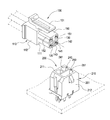
FIGS. 1-4 , which show the first embodiment of the invention. Thepower connector 100 of the invention includes aplug 110 and areceptacle 200. Theplug 100 includes aninsulative body 110, twofirst plug terminals 120 and twosecond plug terminals 130. - The
insulative body 110 is a substantial hexahedron, which is preferably made of plastic. Theinsulative body 110 has abody top 111 and fourbody sides 112 around thebody top 111. The body sides 112 perpendicularly connect to thebody top 111. Twofirst bars 140 and asecond bar 150 are extended from thebody top 111. One of thebody sides 112 is formed with a hookedrod 101. Preferably, thehooked rod 101 extends over thebody top 111. Thefirst bars 140 andsecond bar 150 are arranged at a space. Thefirst bars 140 are cuboids. Each of thefirst bars 140 is longitudinally formed with only onefirst channel 141. Preferably, two angles of each of thefirst bars 140 are separately formed with two firstouter chamfers 142. Thesecond bar 150 is a cuboid. A width of at least one edge of thesecond bar 150 is greater than a maximum width of an edge of thefirst bar 140. Thesecond bar 150 is longitudinally formed with twosecond troughs 151. Preferably, the twosecond troughs 151 are parallel with each other and arranged at a space. Two angles of each of thesecond bar 150 are separately formed with two secondouter chamfers 152. In this embodiment, thefirst channels 141 andsecond troughs 151 are parallel. Preferably, thefirst channels 141 are arranged in a row and thesecond troughs 151 are arrange in another row. - The first and
second plug terminals first plug terminals 120 is received in one of thefirst channels 141. Each of thesecond plug terminals 130 is received in one of thesecond troughs 151. - The
receptacle 200 is used to connect theplug 100 and includes aninsulative seat 210, twofirst receptacle terminals 220 and twosecond receptacle terminals 230. - The
insulative seat 210 is a substantial hexahedron, which is preferably made of plastic. Theinsulative seat 210 has aseat top 211 and fourseat sides 212 around theseat top 211. Afirst trough 240 for being inserted by thefirst bar 140 and asecond trough 250 for being inserted by thesecond bar 150 are extended from theseat top 211. One of theseat sides 212 is formed with a hookedprotrusion 201 for engaging with the hookedrod 101. The first andsecond troughs second bars first troughs 240 and asecond trough 250. Preferably, two angles of each of thefirst troughs 240 are separately formed with two firstinner chamfers 241 corresponding to the firstouter chamfers 142. Each of thesecond troughs 250 is longitudinally formed with twosecond troughs 151. Preferably, the twosecond troughs 151 are parallel with each other and arranged at a space. Two angles of each of thesecond troughs 150 are separately formed with two secondinner chamfers 251 corresponding to the secondouter chamfers 152. Thefirst receptacle terminals 220 are poles made of metal and have an outline corresponding to thefirst plug terminals 120. Each of thefirst receptacle terminals 220 is received in one of thefirst troughs 240. - The
second receptacle terminals 230 are poles made of metal and similar to thefirst receptacle terminals 220 in structure. Thesecond receptacle terminals 230 are used to connect thesecond plug terminals 130. Thesecond receptacle terminals 230 are received in thesecond trough 250. Thesecond receptacle terminals 230 are parallel and arranged in a row. Each of thefirst receptacle terminals 220 passes through the bottom of thefirst trough 240. Each of thesecond receptacle terminals 230 passes through the bottom of thesecond trough 250. - Please refer to
FIGS. 4 and 5 . When theplug 100 and thereceptacle 200 are coupled in a correct direction, thefirst bars 140 and thesecond bar 150 are inserted into thefirst troughs 240 and thesecond trough 250, respectively. And thehooked rod 101 engages with thehooked protrusion 201 so that theplug 100 can firmly couple with thereceptacle 200. - Please refer to
FIG. 6 . When theplug 100 and thereceptacle 200 are coupled in an incorrect direction, thesecond bar 150 cannot be inserted into thefirst trough 240. Furthermore, because thefirst bar 140 has the firstouter chamfer 142 and thefirst trough 240 has the firstinner chamfer 241, thefirst bar 140 cannot be inserted into thefirst trough 240. As a result, the invention allows theplug 100 andreceptacle 200 to be coupled only in a correct direction. - Please refer to
FIGS. 7-9 , which show a second embodiment of the invention. In this embodiment, theinsulative body 110 of theplug 100 has threefirst bars 140 and asecond bar 150. Each of thefirst bars 140 receives one of thefirst plug terminals 120. Thesecond bar 150 has threesecond channels 151 for separately receiving the threesecond plug terminals 130. The first andsecond plug terminals receptacle 200 corresponds to theplug 100. Theinsulative seat 210 is formed with threefirst troughs 240 and asecond trough 250. Each of thefirst troughs 240 receives one of thefirst receptacle terminals 220 and thesecond trough 250 receives threefirst receptacle terminals 220. - Please refer to
FIGS. 10-11 , which show a third embodiment of the invention. In this embodiment, theinsulative body 110 of theplug 100 has fourfirst bars 140 and twosecond bars 150. Each of thefirst bars 140 receives one of thefirst plug terminals 120. Each of thesecond bars 150 has twosecond channels 151 for separately receiving the twosecond plug terminals 130. - The first and
second plug terminals receptacle 200 corresponds to theplug 100. Theinsulative seat 210 is formed with fourfirst troughs 240 and twosecond troughs 250. Each of thefirst troughs 240 receives one of thefirst receptacle terminals 220 and each of thesecond troughs 250 receives twofirst receptacle terminals 220. - Please refer to
FIGS. 12-13 , which show a fourth embodiment of the invention. In this embodiment, theinsulative body 110 of theplug 100 has eightfirst bars 140 and twosecond bars 150. Each of thefirst bars 140 receives one of thefirst plug terminals 120. Each of thesecond bars 150 has twosecond channels 151 for separately receiving the twosecond plug terminals 130. The first andsecond plug terminals first plug terminals 120 and the other row includes twofirst plug terminals 120 and foursecond plug terminals 130. Thereceptacle 200 corresponds to theplug 100. Theinsulative seat 210 is formed with eightfirst troughs 240 and twosecond troughs 250. Each of thefirst troughs 240 receives one of thefirst receptacle terminals 220 and each of thesecond troughs 250 receives twofirst receptacle terminals 220.
Claims (12)
Priority Applications (1)
| Application Number | Priority Date | Filing Date | Title |
|---|---|---|---|
| US13/938,353 US8998651B2 (en) | 2013-07-10 | 2013-07-10 | Plug having a body with a plurality of bars in a first direction and a second direction each with a channel to accommodate a terminal |
Applications Claiming Priority (1)
| Application Number | Priority Date | Filing Date | Title |
|---|---|---|---|
| US13/938,353 US8998651B2 (en) | 2013-07-10 | 2013-07-10 | Plug having a body with a plurality of bars in a first direction and a second direction each with a channel to accommodate a terminal |
Publications (2)
| Publication Number | Publication Date |
|---|---|
| US20150017841A1 true US20150017841A1 (en) | 2015-01-15 |
| US8998651B2 US8998651B2 (en) | 2015-04-07 |
Family
ID=52277429
Family Applications (1)
| Application Number | Title | Priority Date | Filing Date |
|---|---|---|---|
| US13/938,353 Active 2033-07-26 US8998651B2 (en) | 2013-07-10 | 2013-07-10 | Plug having a body with a plurality of bars in a first direction and a second direction each with a channel to accommodate a terminal |
Country Status (1)
| Country | Link |
|---|---|
| US (1) | US8998651B2 (en) |
Cited By (15)
| Publication number | Priority date | Publication date | Assignee | Title |
|---|---|---|---|---|
| US10033142B1 (en) | 2016-04-20 | 2018-07-24 | Cooper Technologies Company | Configurable low profile conduit connector system for light fixtures |
| USD851595S1 (en) * | 2019-02-18 | 2019-06-18 | Zhejiang Shijian Import and Export Co., Ltd. | Power connector |
| KR20190074949A (en) * | 2017-12-20 | 2019-06-28 | 히로세덴끼 가부시끼가이샤 | Power connector and power connector apparatus |
| US10358202B2 (en) | 2016-08-01 | 2019-07-23 | Pure Watercraft, Inc. | Electric marine propulsion systems with drive trains, and associated systems and methods |
| US10511121B2 (en) | 2017-11-13 | 2019-12-17 | Pure Watercraft, Inc. | Cable connection assemblies for marine propulsion, and associated systems and methods |
| USD880427S1 (en) | 2017-11-13 | 2020-04-07 | Pure Watercraft, Inc. | Cable connector |
| USD884644S1 (en) * | 2017-11-13 | 2020-05-19 | Pure Watercraft, Inc. | Power connector |
| USD891362S1 (en) | 2017-11-13 | 2020-07-28 | Pure Watercraft, Inc. | Battery pack |
| USD892744S1 (en) * | 2020-03-25 | 2020-08-11 | Qingdao Cailing Trading Co., Ltd. | Power connector |
| USD924171S1 (en) * | 2019-09-05 | 2021-07-06 | Shenzhen Intellirocks Tech. Co., Ltd | Connection buckle |
| USD927426S1 (en) | 2019-10-04 | 2021-08-10 | Physio-Control, Inc. | Medical device connector |
| USD931219S1 (en) | 2019-10-04 | 2021-09-21 | Physio-Control, Inc. | Medical device connector |
| USD933607S1 (en) | 2019-10-04 | 2021-10-19 | Physio-Control, Inc. | Medical device connector |
| US11183739B2 (en) | 2017-11-13 | 2021-11-23 | Pure Watercraft, Inc. | Batteries for electric marine propulsion systems, and associated systems and methods |
| US11342761B2 (en) | 2015-10-22 | 2022-05-24 | Pure Watercraft, Inc. | Battery fleet charging system |
Citations (5)
| Publication number | Priority date | Publication date | Assignee | Title |
|---|---|---|---|---|
| US6196874B1 (en) * | 1998-06-02 | 2001-03-06 | Hon Hai Precision Ind. Co., Ltd. | Plug connector having additional power plug for transmitting high rated power |
| US6471530B1 (en) * | 1999-04-15 | 2002-10-29 | A. Raymond & Cie | Plug-and-socket connection for water-cooled, current-bearing lines for tools |
| US7909652B2 (en) * | 2008-08-11 | 2011-03-22 | Hon Hai Precision Ind. Co., Ltd. | Electrical connector with two grooves dividing contacts |
| US8092261B2 (en) * | 2004-03-02 | 2012-01-10 | Igo, Inc. | Connector shaped as a function of its power rating |
| US8449312B2 (en) * | 2008-09-09 | 2013-05-28 | Molex Incorporated | Housing with a plurality of wafers and having a nose portion with engagement members |
-
2013
- 2013-07-10 US US13/938,353 patent/US8998651B2/en active Active
Patent Citations (5)
| Publication number | Priority date | Publication date | Assignee | Title |
|---|---|---|---|---|
| US6196874B1 (en) * | 1998-06-02 | 2001-03-06 | Hon Hai Precision Ind. Co., Ltd. | Plug connector having additional power plug for transmitting high rated power |
| US6471530B1 (en) * | 1999-04-15 | 2002-10-29 | A. Raymond & Cie | Plug-and-socket connection for water-cooled, current-bearing lines for tools |
| US8092261B2 (en) * | 2004-03-02 | 2012-01-10 | Igo, Inc. | Connector shaped as a function of its power rating |
| US7909652B2 (en) * | 2008-08-11 | 2011-03-22 | Hon Hai Precision Ind. Co., Ltd. | Electrical connector with two grooves dividing contacts |
| US8449312B2 (en) * | 2008-09-09 | 2013-05-28 | Molex Incorporated | Housing with a plurality of wafers and having a nose portion with engagement members |
Cited By (18)
| Publication number | Priority date | Publication date | Assignee | Title |
|---|---|---|---|---|
| US11342761B2 (en) | 2015-10-22 | 2022-05-24 | Pure Watercraft, Inc. | Battery fleet charging system |
| US10270213B2 (en) | 2016-04-20 | 2019-04-23 | Cooper Technologies Company | Configurable low profile conduit connector system for light fixtures |
| US10033142B1 (en) | 2016-04-20 | 2018-07-24 | Cooper Technologies Company | Configurable low profile conduit connector system for light fixtures |
| US10358202B2 (en) | 2016-08-01 | 2019-07-23 | Pure Watercraft, Inc. | Electric marine propulsion systems with drive trains, and associated systems and methods |
| USD891362S1 (en) | 2017-11-13 | 2020-07-28 | Pure Watercraft, Inc. | Battery pack |
| US11183739B2 (en) | 2017-11-13 | 2021-11-23 | Pure Watercraft, Inc. | Batteries for electric marine propulsion systems, and associated systems and methods |
| USD880427S1 (en) | 2017-11-13 | 2020-04-07 | Pure Watercraft, Inc. | Cable connector |
| USD884644S1 (en) * | 2017-11-13 | 2020-05-19 | Pure Watercraft, Inc. | Power connector |
| US10511121B2 (en) | 2017-11-13 | 2019-12-17 | Pure Watercraft, Inc. | Cable connection assemblies for marine propulsion, and associated systems and methods |
| KR20190074949A (en) * | 2017-12-20 | 2019-06-28 | 히로세덴끼 가부시끼가이샤 | Power connector and power connector apparatus |
| KR102353873B1 (en) | 2017-12-20 | 2022-01-19 | 히로세덴끼 가부시끼가이샤 | Power connector and power connector apparatus |
| USD851595S1 (en) * | 2019-02-18 | 2019-06-18 | Zhejiang Shijian Import and Export Co., Ltd. | Power connector |
| USD924171S1 (en) * | 2019-09-05 | 2021-07-06 | Shenzhen Intellirocks Tech. Co., Ltd | Connection buckle |
| USD927426S1 (en) | 2019-10-04 | 2021-08-10 | Physio-Control, Inc. | Medical device connector |
| USD931219S1 (en) | 2019-10-04 | 2021-09-21 | Physio-Control, Inc. | Medical device connector |
| USD933607S1 (en) | 2019-10-04 | 2021-10-19 | Physio-Control, Inc. | Medical device connector |
| USD994607S1 (en) | 2019-10-04 | 2023-08-08 | Physio-Control, Inc. | Medical device connector |
| USD892744S1 (en) * | 2020-03-25 | 2020-08-11 | Qingdao Cailing Trading Co., Ltd. | Power connector |
Also Published As
| Publication number | Publication date |
|---|---|
| US8998651B2 (en) | 2015-04-07 |
Similar Documents
| Publication | Publication Date | Title |
|---|---|---|
| US20150017841A1 (en) | Plug and receptacle of power connector | |
| US20150126075A1 (en) | Power plug and power receptacle | |
| US10218088B2 (en) | Cable connector assembly | |
| US9780476B2 (en) | Electrical connector having improved terminal arrangement | |
| US8845351B2 (en) | Connector housing with alignment guidance feature | |
| WO2014116694A3 (en) | Reversible usb connector | |
| US9112309B1 (en) | Network connector socket | |
| KR20140001479U (en) | Connector | |
| MX347330B (en) | Electrical connector with reduced stack height. | |
| CN107112665A (en) | Mezzanine-style connector | |
| JP2016115625A5 (en) | ||
| CN103529251A (en) | Combined secondary terminal short circuit wiring bar | |
| US9714760B2 (en) | Light fixture installation mounting device | |
| US20150288080A1 (en) | Harness assembly | |
| US20120258626A1 (en) | Housing Insert Contact Protection | |
| US9728872B2 (en) | Connector plug, connector socket, and connector | |
| CN204424524U (en) | Electric connector | |
| CN205882239U (en) | Plug connector , socket connector and connector component | |
| CN204538367U (en) | Electric connector | |
| US9614329B2 (en) | Power plug, power receptacle and power connector assembly | |
| US20130137311A1 (en) | Connector assembly | |
| CN214411611U (en) | Connector shell, connector and connector assembly | |
| CN205051085U (en) | Electric connector assembly | |
| CN204011784U (en) | Wire and cable connector | |
| CN202749556U (en) | Terminal structure improvement |
Legal Events
| Date | Code | Title | Description |
|---|---|---|---|
| AS | Assignment |
Owner name: BELLWETHER ELECTRONIC CORP., TAIWAN Free format text: ASSIGNMENT OF ASSIGNORS INTEREST;ASSIGNORS:CHEN, KUAN-WU;LEE, HSING-YU;REEL/FRAME:030765/0878 Effective date: 20130605 |
|
| STCF | Information on status: patent grant |
Free format text: PATENTED CASE |
|
| MAFP | Maintenance fee payment |
Free format text: PAYMENT OF MAINTENANCE FEE, 4TH YR, SMALL ENTITY (ORIGINAL EVENT CODE: M2551); ENTITY STATUS OF PATENT OWNER: SMALL ENTITY Year of fee payment: 4 |
|
| MAFP | Maintenance fee payment |
Free format text: PAYMENT OF MAINTENANCE FEE, 8TH YR, SMALL ENTITY (ORIGINAL EVENT CODE: M2552); ENTITY STATUS OF PATENT OWNER: SMALL ENTITY Year of fee payment: 8 |