US20160363256A1 - Snap-together stand for a fan - Google Patents
Snap-together stand for a fan Download PDFInfo
- Publication number
- US20160363256A1 US20160363256A1 US15/177,952 US201615177952A US2016363256A1 US 20160363256 A1 US20160363256 A1 US 20160363256A1 US 201615177952 A US201615177952 A US 201615177952A US 2016363256 A1 US2016363256 A1 US 2016363256A1
- Authority
- US
- United States
- Prior art keywords
- vertical
- stubs
- posts
- vertical posts
- depressible
- Prior art date
- Legal status (The legal status is an assumption and is not a legal conclusion. Google has not performed a legal analysis and makes no representation as to the accuracy of the status listed.)
- Granted
Links
Images


Classifications
-
- F—MECHANICAL ENGINEERING; LIGHTING; HEATING; WEAPONS; BLASTING
- F04—POSITIVE - DISPLACEMENT MACHINES FOR LIQUIDS; PUMPS FOR LIQUIDS OR ELASTIC FLUIDS
- F04D—NON-POSITIVE-DISPLACEMENT PUMPS
- F04D29/00—Details, component parts, or accessories
- F04D29/60—Mounting; Assembling; Disassembling
- F04D29/601—Mounting; Assembling; Disassembling specially adapted for elastic fluid pumps
-
- A—HUMAN NECESSITIES
- A47—FURNITURE; DOMESTIC ARTICLES OR APPLIANCES; COFFEE MILLS; SPICE MILLS; SUCTION CLEANERS IN GENERAL
- A47F—SPECIAL FURNITURE, FITTINGS, OR ACCESSORIES FOR SHOPS, STOREHOUSES, BARS, RESTAURANTS OR THE LIKE; PAYING COUNTERS
- A47F5/00—Show stands, hangers, or shelves characterised by their constructional features
- A47F5/10—Adjustable or foldable or dismountable display stands
- A47F5/106—Adjustable or foldable or dismountable display stands with independent pillars
-
- F—MECHANICAL ENGINEERING; LIGHTING; HEATING; WEAPONS; BLASTING
- F04—POSITIVE - DISPLACEMENT MACHINES FOR LIQUIDS; PUMPS FOR LIQUIDS OR ELASTIC FLUIDS
- F04D—NON-POSITIVE-DISPLACEMENT PUMPS
- F04D25/00—Pumping installations or systems
- F04D25/02—Units comprising pumps and their driving means
- F04D25/08—Units comprising pumps and their driving means the working fluid being air, e.g. for ventilation
-
- F—MECHANICAL ENGINEERING; LIGHTING; HEATING; WEAPONS; BLASTING
- F04—POSITIVE - DISPLACEMENT MACHINES FOR LIQUIDS; PUMPS FOR LIQUIDS OR ELASTIC FLUIDS
- F04D—NON-POSITIVE-DISPLACEMENT PUMPS
- F04D29/00—Details, component parts, or accessories
- F04D29/60—Mounting; Assembling; Disassembling
-
- F—MECHANICAL ENGINEERING; LIGHTING; HEATING; WEAPONS; BLASTING
- F04—POSITIVE - DISPLACEMENT MACHINES FOR LIQUIDS; PUMPS FOR LIQUIDS OR ELASTIC FLUIDS
- F04D—NON-POSITIVE-DISPLACEMENT PUMPS
- F04D29/00—Details, component parts, or accessories
- F04D29/60—Mounting; Assembling; Disassembling
- F04D29/64—Mounting; Assembling; Disassembling of axial pumps
- F04D29/644—Mounting; Assembling; Disassembling of axial pumps especially adapted for elastic fluid pumps
- F04D29/646—Mounting or removal of fans
-
- F—MECHANICAL ENGINEERING; LIGHTING; HEATING; WEAPONS; BLASTING
- F16—ENGINEERING ELEMENTS AND UNITS; GENERAL MEASURES FOR PRODUCING AND MAINTAINING EFFECTIVE FUNCTIONING OF MACHINES OR INSTALLATIONS; THERMAL INSULATION IN GENERAL
- F16M—FRAMES, CASINGS OR BEDS OF ENGINES, MACHINES OR APPARATUS, NOT SPECIFIC TO ENGINES, MACHINES OR APPARATUS PROVIDED FOR ELSEWHERE; STANDS; SUPPORTS
- F16M11/00—Stands or trestles as supports for apparatus or articles placed thereon Stands for scientific apparatus such as gravitational force meters
- F16M11/20—Undercarriages with or without wheels
- F16M11/22—Undercarriages with or without wheels with approximately constant height, e.g. with constant length of column or of legs
-
- F—MECHANICAL ENGINEERING; LIGHTING; HEATING; WEAPONS; BLASTING
- F16—ENGINEERING ELEMENTS AND UNITS; GENERAL MEASURES FOR PRODUCING AND MAINTAINING EFFECTIVE FUNCTIONING OF MACHINES OR INSTALLATIONS; THERMAL INSULATION IN GENERAL
- F16M—FRAMES, CASINGS OR BEDS OF ENGINES, MACHINES OR APPARATUS, NOT SPECIFIC TO ENGINES, MACHINES OR APPARATUS PROVIDED FOR ELSEWHERE; STANDS; SUPPORTS
- F16M11/00—Stands or trestles as supports for apparatus or articles placed thereon Stands for scientific apparatus such as gravitational force meters
- F16M11/20—Undercarriages with or without wheels
- F16M11/24—Undercarriages with or without wheels changeable in height or length of legs, also for transport only, e.g. by means of tubes screwed into each other
-
- F—MECHANICAL ENGINEERING; LIGHTING; HEATING; WEAPONS; BLASTING
- F05—INDEXING SCHEMES RELATING TO ENGINES OR PUMPS IN VARIOUS SUBCLASSES OF CLASSES F01-F04
- F05D—INDEXING SCHEME FOR ASPECTS RELATING TO NON-POSITIVE-DISPLACEMENT MACHINES OR ENGINES, GAS-TURBINES OR JET-PROPULSION PLANTS
- F05D2240/00—Components
- F05D2240/90—Mounting on supporting structures or systems
- F05D2240/91—Mounting on supporting structures or systems on a stationary structure
Definitions
- Example embodiments relate generally to a stand capable of being assembled without tools. More particularly, example embodiments relate to a stand that horizontally and vertically stabilizes a motorized device, such as a fan, that may experience vibration while in use.
- a motorized device such as a fan
- consumer products such as a motorized fan that may be purchased in a box often require some amount of assembly or setup in order to operate the product.
- Such products often times requires the use of a screwdriver, a hex key (Allen wrench), a conventional wrench, a ratchet set, or other tools that may or may not be provided with the product in order to fully assembly and use the product.
- the end consumer may not have the tools necessary to assembly the product.
- tools may be shipped with the product, thereby increasing the overall manufacturing cost and sale cost of the product.
- At least one example embodiments relates to a kit for a stand holding an electronic device.
- the kit includes at least a first and a second lower vertical post; a horizontal support bar with at least a first and a second lower vertical stub and at least a first and second upper vertical stub, a first end of each of the lower vertical posts being connectable to the respective first and second lower vertical stubs via at least two points of contact; at least a first and a second upper vertical post, a first end of each of the upper vertical posts being connectable to the respective first and second upper vertical stubs via at least two points of contact; and a first and a second side clip, each of the side clips being connected to the electronic device, the side clips being configured to slide onto the respective first and second upper vertical posts, the side clips being configured to selectively grip the respective first and second upper vertical posts at positions along a longitudinal length of the respective first and second upper vertical posts, wherein the kit is configured to be assembled into the stand without requiring tools.
- the kit further includes a base with at least a first and a second bottom vertical stub, a second end of each of the lower vertical posts being connectable to the respective first and second bottom vertical stubs of the base via at least two points of contact.
- the first end of each of the lower vertical posts define a lower aperture and a lower notch that are respectively mateable with a lower depressible stop and a lower physical stop on each of the lower vertical stubs of the horizontal support bar to provide the two points of contact for the connection between the lower vertical stubs of the horizontal support bar and the lower vertical posts.
- each of the lower vertical posts defines a bottom aperture and a bottom notch that are respectively mateable with a bottom depressible stop and a bottom physical stop on each of the bottom vertical stubs of the base to provide the two points of contact for the connection between the lower vertical posts and the bottom vertical stubs of the base.
- the first end of each of the upper vertical posts defines an upper aperture and an upper notch that are respectively mateable with an upper depressible stop and an upper physical stop on each of the upper vertical stubs of the horizontal support bar to provide the two points of contact for the connection between the upper vertical posts and the upper vertical stubs of the horizontal support bar.
- the lower and bottom apertures are on a same first side of the lower vertical posts, and the lower and bottom notches are on a same second side of the lower vertical posts, wherein the apertures and notches of the lower vertical posts are respectively offset from each other by about 180 degrees along a circumference of each of the respective lower vertical posts.
- the bottom vertical stubs of the base are on opposing sides of the base, and the bottom depressible stops of the bottom vertical stubs are facing away from each other on opposing sides of the bottom vertical stubs, wherein the bottom physical stops of the bottom vertical stubs face each other on the bottom vertical stubs.
- the upper and lower depressible stops and the upper physical stops of the respective upper and lower vertical stubs of the horizontal support bar are on a same first side of each of the respective upper and lower vertical stubs, wherein the lower physical stops are on opposing sides of the respective lower vertical stubs relative to a location of the lower depressible stops, the lower physical stops facing each other on the horizontal support bar.
- the lower physical stops of the lower vertical stubs of the horizontal support bar are about 180 degrees offset from the lower depressible stops along a circumference of the lower vertical stubs.
- the electronic device is a fan, wherein each of the side clips are connected to sides of the fan with a socket that allows a front of the fan to pivot in upward and downward angles.
- each of the side clips include a hinged tab facing away from the fan, the hinged tabs of each of the side clips communicating with a gripper positioned along an inner surface of each of the respective side clips, each of the grippers being configured to selectively grip the respective first and second upper vertical posts via selective movement of the hinged tabs.
- the lower vertical posts are longer than the upper vertical posts.
- At least one example embodiments relates to a stand that is capable of being assembled by a method that does not require tools.
- the method includes depressing the bottom depressible stops of the bottom vertical stubs of the base and sliding the second ends of the first and second lower vertical posts onto the respective bottom vertical stubs so that the bottom physical stops mate with the bottom notches and the bottom depressible stops slide into the bottom apertures; depressing the lower depressible stops of the lower vertical stubs of the horizontal support bar and sliding the first ends of the first and second lower vertical posts onto the respective lower vertical stubs so that the lower physical stops mate with the upper notches and the lower depressible stops slide into the upper apertures; and depressing the upper depressible stops of the upper vertical stubs of the horizontal support bar and sliding the ends of the first and second upper vertical posts onto the respective upper vertical posts so that the upper physical stops mate with the lower notches and the upper depressible stops slide into the lower apertures.
- the method further includes sliding the first and second side clips onto the respective first and second upper vertical posts; locking the electronic device into a desired vertical elevation along the first and second upper vertical posts using the side clips; and pressing stoppers on top of upper ends of the upper vertical posts.
- At least one example embodiment relates to a stand.
- the stand includes a horizontal support bar; at least a first and second lower vertical post, a first end of each of the lower vertical posts being connected to lower vertical stubs on a lower portion of the horizontal support bar via at least two points of contact; at least a first and second upper vertical post, a first end of each of the upper vertical posts being connected to upper vertical stubs on an upper portion of the horizontal support bar via at least two points of contact; a first and a second side clip, each of the side clips being connected to an electronic device to hold the electronic device between the upper vertical posts, each of the side clips being configured to selectively grip one of the first and second upper vertical posts at positions along a longitudinal length of the respective upper vertical posts, wherein the stand is configured to be assembled without requiring tools.
- the stand further includes a base, wherein a second end of each of the lower vertical posts being connected to bottom vertical stubs on the base via at least two points of contact.
- each of the vertical stubs includes at least two of a physical stop and a depressible stop, and each of the first and second ends of the lower vertical posts, and each of the first ends of the upper vertical posts, defines at least two of a notch and an aperture that are mateable with the respective physical stops and depressible stops of the vertical stubs to provide the two points of contact.
- each of the vertical stubs includes a physical stop and a depressible stop, the upper vertical stubs of the horizontal support bar having an upper depressible stop and an upper physical stop on a same side of the upper vertical stubs.
- the lower vertical stubs of the horizontal support bar, and the bottom vertical stubs of the base each have a lower depressible stop and a lower physical stop on opposing sides of the respective lower and bottom stubs, the respective lower and bottom physical stops of the lower and bottom vertical stubs facing inward toward each other.
- the electronic device is a fan, each of the side clips being connected to sides of the fan via a socket that allows a front of the fan to pivot in upward and downward angles, the side clips including a hinged tab facing away from the fan and being in communication with a gripper positioned along an inner surface of each of the side clips, the gripper being configured to selectively grip the respective first and second upper vertical posts.
- FIG. 1 is an illustration of a perspective view of an assembled stand, in accordance with an example embodiment
- FIG. 2 is an illustration of a perspective view of an assembled stand, holding a fan, in accordance with an example embodiment
- FIG. 3 is an illustration of a perspective view of a base of a stand, in accordance with an example embodiment
- FIG. 4 is an illustration of a side view of the base of the stand shown in FIG. 3 , in accordance with an example embodiment
- FIG. 5 is an illustration of a perspective view of a vertical lower post for a stand, in accordance with an example embodiment
- FIG. 6 is an illustration of a side view of the vertical lower post shown in FIG. 5 , in accordance with an example embodiment
- FIG. 7 is an illustration of a vertical lower post being installed on a base of a stand, in accordance with an example embodiment
- FIG. 8 is another illustration of another perspective of the vertical lower post being installed on the base of the stand shown in FIG. 7 , in accordance with an example embodiment
- FIG. 9 is an illustration of a perspective view of a support bar of a stand, in accordance with an example embodiment
- FIG. 10 is an illustration of a side view of the support bar shown in FIG. 9 , in accordance with an example embodiment
- FIG. 11 is an illustration of the support bar shown in FIG. 9 being installed on a vertical lower post, in accordance with an example embodiment
- FIG. 12 is an illustration of a side view of a vertical upper post of a stand, in accordance with an example embodiment
- FIG. 13 is an illustration of a lower portion of a side clip of a stand, in accordance with an example embodiment
- FIG. 14 is an illustration of an upper portion of a side clip of a stand, in accordance with an example embodiment
- FIG. 15 is an illustration of a perspective view of the upper portion and lower portion of FIGS. 13 and 14 being connected together, in accordance with an example embodiment
- FIG. 16 illustrates an illustration of a side view of the upper portion and lower portion of FIGS. 13 and 14 , in accordance with an example embodiment
- FIG. 17 is an illustration of a perspective view of an assembled side clip of a stand, in accordance with an example embodiment
- FIG. 18 is an illustration of another perspective view of the assembled side clip shown in FIG. 17 , in accordance with an example embodiment
- FIG. 19 is an illustration of a perspective view of the assembled side clip shown in FIG. 17 , installed on a vertical upper post, in accordance with an example embodiment
- FIG. 20 is an illustration of another perspective view of the assembled side clip shown in FIG. 17 , installed on the vertical upper post, in accordance with an example embodiment
- FIG. 21 is an illustration of a vertical upper post being installed on a support bar, in accordance with an example embodiment
- FIG. 22 is an illustration of an exploded view of an unassembled stand, in accordance with an example embodiment.
- FIG. 23 is an illustration of a side view of an assembled stand, in accordance with an example embodiment.
- FIG. 1 is an illustration of a perspective view of an assembled stand 10 , in accordance with an example embodiment.
- the stand 10 may include a supportive base 2 that may be wide enough to potentially withstand vibration while the stand 10 is in use.
- the stand 10 may also include vertical lower posts 4 connected to the base 2 . While two vertical lower posts 4 are shown in this example embodiment, it should be understood that one vertical lower post 4 may be used rather than two posts 4 (not shown). Alternatively, more than two posts 4 may also be used (not shown).
- a support bar 6 may be used to hold a top portion f the vertical lower posts 4 together, in order to stabilize the stand 10 , especially in the event that the stand 10 may experience vibration while in use. It should be understood that a support bar 6 would not be utilized in the event that only a single lower post 4 is used. Furthermore, in the event that more than two lower posts 4 are used for the stand 10 , a single support bar 6 may be used to connect a top portion of each of the lower posts together (not shown). Alternatively, in the event that more than two lower posts 4 are used for the stand 10 , more than one support bar 6 may be used to connect the lower posts 4 to each other.
- a single support bar 6 may be used to connect two (or more) lower posts 4 to each other, such that multiple support bars 6 may then be used in order to ultimately connect each lower post 4 to another adjacent lower post 4 .
- two or three support bars 6 may be used to connect each lower post 4 to at least one other adjacent lower post 4 (not shown).
- Vertical upper posts 8 may be connected to the support bar 6 .
- two upper posts 8 are shown. However, in a stand configuration with only one vertical lower post 4 , only a single upper post 8 may be used. Alternatively, in the event that more than two lower posts 4 for the stand 10 , more than two upper posts 8 may also be used to add extra support and stability to the stand 10 .
- Side clips 12 may be included on the upper posts 8 .
- the clips 12 may be used to hold a fan 20 (for instance) between the upper posts 8 (see this shown in FIG. 2 ).
- a number of side clips 12 may equal a number of upper posts 8 .
- the side clips may be attached to the lower posts 4 , such that the stand 10 may not include upper posts 8 .
- Stoppers 14 may be fitted onto a top end of the upper posts 8 .
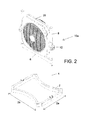
- FIG. 2 is an illustration of a perspective view of an assembled stand 10 a , holding a fan 20 , in accordance with an example embodiment.
- the clips may connect to side surfaces of the fan 20 in order to securely hold the fan between the upper posts 8 of the stand 10 a (that includes the fan 20 ).
- a length of the upper posts 8 may be approximately equal to a length of the fan 20 . This will allow the support bar 6 to be positioned relatively close to the fan 20 itself, in order for the overall stability of the stand 10 a to be improved in holding the fan 20 , especially in the event that the fan 20 may be expected to produce some amount of vibration while in use.
- the lower posts 4 may be slightly longer than the upper posts 8 .
- an overall height of the stand 10 a may be increased, while still affording a high degree of stability for the stand 10 a , as the use of relatively shorter upper posts 8 may more firmly grip the sides of the fan 20 (i.e., the portion of the stand 10 a located closest to a source of vibration), even if an overall height of the stand 10 a is significantly taller than the fan 20 height.
- a width 2 a portion of the base 2 (which runs about perpendicular to a length 2 b of the base 2 spanning between the lower posts 4 ) may extend away from the lower posts 4 .
- the base 2 shown in FIGS. 1-4 has a somewhat rectangular footprint (with the width 2 a being somewhat shorter than the length 2 b ), it should be understood that a somewhat square footprint may also be utilized.
- a circular or triangular-shaped footprint (or, another shape) may also be utilized for the base 2 .
- FIG. 2 shows the stand 10 a holding a fan 20
- the stand 10 a may alternatively hold another device besides a fan.
- FIG. 3 is an illustration of a perspective view of a base of a stand 2 , in accordance with an example embodiment.
- the stand 2 may include one or more vertical stubs 3 connected to a top portion of the base 2 .
- Each of the vertical stubs 3 may include one or more stops.
- each stub 3 may include a physical stop 3 b , which may be positioned near a juncture between the stub 3 and a top portion of the base (shown in more detail in FIG. 4 ).
- Each stub 3 may also include a depressible stop 3 a (also shown in FIG. 4 ).
- the depressible stop 3 a may be configured to allow an end user to depress an outer surface of the stop 3 a so that a portion of a lower post 4 may clear the stop 3 a (shown in better detail in FIG. 7 ).
- FIG. 4 is an illustration of a side view of the base 2 shown in FIG. 3 , in accordance with an example embodiment.
- the depressible stop 3 a and the physical stop 3 b may be located on opposite sides of each stub 3 (such that the depressible stop 3 a and the physical stop 3 b are positioned about 180 degrees apart from each other on an outer surface of each stub 3 ).
- the depressible stop 3 a and the physical stop 3 b may be positioned on a same side of each stub 3 .
- the depressible stub 3 a and the physical stop 3 b may be spaced apart along an outer surface of the stub 3 using a different spacing than shown in FIG. 4 (such as 90 degrees apart, or 45 degrees, for example).
- FIG. 5 is an illustration of a perspective view of a vertical lower post 4 for a stand 10 , in accordance with an example embodiment.
- the lower post 4 may include one or more notches or apertures.
- the lower post 4 may include an upper notch 4 b ′ and an upper aperture 4 a ′ located near a top portion of the lower post 4 .
- An identical lower notch 4 b (shown in FIG. 6 ) and lower aperture 4 a may also be located near a bottom portion of the lower post 4 .
- the lower notch 4 b may be mateable with the physical stop 3 b of the base 2 .
- the lower aperture 4 a may be mateable with the depressible stop 3 a and the base 2 .
- the upper notch 4 b ′ and upper aperture 4 a ′ may be respectively mateable with a lower physical stop 5 b and lower depressible stop 5 a of a support bar 6 (see FIGS. 9-11 ).
- FIG. 6 is an illustration of a side view of the vertical lower post 4 shown in FIG. 5 , in accordance with an example embodiment.
- FIG. 6 shows in better detail the location of the notches 4 b / 4 b ′ and apertures 4 a / 4 a ′ that may be included on the post 4 .
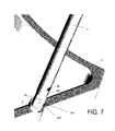
- FIG. 7 is an illustration of a vertical lower post 4 being installed on a base 2 of a stand 10 , in accordance with an example embodiment.
- FIG. 7 shows an alignment of the depressible stop 3 a (on stub 3 ) with lower aperture 4 a of the lower post 4 .
- the depressible stop 3 a may include an angled portion 3 a 1 that may allow an end 4 a 1 of the lower post 4 to slide over the depressible stop 3 a , such that the end portion 4 a 1 of the post 4 may force the depressible stop 3 a to be pressed inwards within the post 4 .
- the depressible stop 3 a may flare outward, so that the stop 3 a may fill the aperture 4 a .
- a lower edge 3 a 2 of the stop 2 a may retard the lower post from being inadvertently separated from base 2 .
- an end user may press the depressible stop 3 a in order to allow the stop 3 a to clear the lower portion 4 a 1 of the lower post 4 in order to intentionally remove the lower post 4 from the base 2 (during disassembly of the stand 10 , for instance).
- FIG. 8 is another illustration of another perspective of the vertical lower post 4 being installed on the base 2 of the stand 10 shown in FIG. 7 , in accordance with an example embodiment.
- FIG. 8 shows an alignment between lower notch 4 a and physical stop 3 b as the lower post 4 is fitted onto base 2 .
- the mating of the physical stop 3 b with notch 4 a , and the mating of depressible stop 3 a with aperture 4 a may act as a two-point contact that allows post 4 to resist rotation while post 4 is fitted onto base 2 .
- the post 4 may include only an aperture 4 a that is mateable with depressible stop 3 a (devoid of notch 4 a and physical stop 3 b ).
- more apertures or more notches may alternatively be included on an end of post 4 , which may be mateable with respective physical stops or depressible stops.
- FIG. 9 is an illustration of a perspective view of a support bar 6 of a stand, in accordance with an example embodiment.
- the support bar 6 may include vertical lower stubs 5 and vertical upper stubs 7 .
- the lower stubs 5 may each include a lower physical stop 5 b and a lower depressible stop 5 a on an outer surface of the stubs 5 . Similar to the stubs 3 of base 2 , the position of the lower physical stops 5 b and lower depressible stops 5 a may vary (although the lower physical stops 5 b and lower depressible stops 5 a are shown to be 180 degrees apart from each other, on an outer surface of stubs 5 , in the example embodiment of FIG. 9 ).
- FIG. 10 is an illustration of a side view of the support bar 6 shown in FIG. 9 , in accordance with an example embodiment.
- FIG. 10 shows in better detail, the positions of the lower depressible stop 5 a , the lower physical stop 5 b , the upper depressible stop 7 a , and the upper physical stop 7 b .
- the precise positions of the depressible stops and physical stops may change. Additionally, as indicated above, only depressible stops may be used, such that the physical stops may be excluded. Alternatively, more depressible stops, or more physical stops, may also be used.
- FIG. 11 is an illustration of the support bar 6 shown in FIG. 9 being installed on a vertical lower post 4 , in accordance with an example embodiment.
- lower depressible stop 5 a may align with the upper aperture 4 a ′ of post 4 , just as upper notch 4 b ′ may also align with lower physical stop 5 b .
- the depressible stop 5 a may allow an upper portion 4 a 2 ′ to clear the stop 5 a , and once the support bar 6 is firmly pressed onto the lower post 4 , the stop 5 a may projected through aperture 4 a ′ to cause support bar 6 to be physically secured to post 4 .
- FIG. 12 is an illustration of a side view of a vertical upper post 8 of a stand 10 , in accordance with an example embodiment.
- the upper post 8 may be similar to lower post 4 , with the exception that lower apertures 8 a and lower notch 8 b may be on a same side of post 8 , whereas the upper aperture 8 a ′ and upper notch 8 b ′ may also be on a same side of post 8 , although the aperture 8 a ′ and notch 8 b ′ may be on an opposite side of the post 8 as compared to aperture 8 a and notch 8 b.
- FIG. 13 is an illustration of a lower portion 12 a of a side clip 12 of a stand 10 , in accordance with an example embodiment.
- the lower portion may include one more prongs 12 a 1 / 12 a 2 that may be mateable with holes 12 b 1 / 12 b 2 (or recesses) of an upper portion 12 b of the side clip 12 (see the upper portion 12 b in FIG. 14 ).
- the prongs 12 a 1 / 12 a 2 and holes 12 b 1 / 12 b 2 may be utilized to help the lower portion 12 a and the upper portion 12 b of the clip 12 stay connected together while in use.
- Other means of connecting the lower portion 12 a and upper portion 12 b of the clip together such as clips, snap-fit components, frictional couplings, etc., may also be utilized.
- a bolt hole 12 a 4 running clear-through the lower portion 12 a may be provided in order to bolt the lower portion 12 a directly to the fan.
- FIG. 14 is an illustration of an upper portion 12 b of a side clip 12 of a stand 10 , in accordance with an example embodiment.
- the upper portion may include a socket 12 b 3 , or other comparable structure, that may be used to connect the upper portion 12 b of the clip 12 to the side surface of the fan 20 . Therefore, the clip 12 may be connected to the fan 20 via two points of contact: 1) the socket 12 b 3 connecting upper portion 12 b to the fan 20 , and 2) a bolt running though bolt hole 12 a 4 connecting lower portion 12 a to the fan 20 .
- FIG. 15 is an illustration of a perspective view of the upper portion 12 b and lower portion 12 a of FIGS. 13 and 14 being connected together, in accordance with an example embodiment.
- a beveled edge 12 b 4 of the upper portion 12 b may be provided in order to frictionally fit within an upper lip 12 a 3 of the lower portion 12 a in order to further secure the portions 12 a / 12 b to each other.
- FIG. 16 illustrates a side view of the upper portion 12 b and lower portion 12 a of a FIGS. 13 and 14 , in accordance with an example embodiment.
- FIG. 16 shows socket 12 b 3 of the upper portion 12 b in better detail, where a socket hole 12 b 3 a may be provided to engage a spindle (not shown) connected to the fan 20 .
- the socket 12 b 3 may be configured to allow the fan 20 to pivot between opposing clips 12 (see FIG. 2 ) connected to the upper posts 8 , so that the fan may be pivoted to face a more upward angle or a more downward angle based on an end user preference.
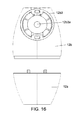
- FIG. 17 is an illustration of a perspective view of an assembled side clip 12 of a stand 10 , in accordance with an example embodiment.
- a hole 12 a 5 through the lower portion 12 a of the clip 12 , and a respective hole 12 b 5 through the upper portion 12 b of the clip 12 may be included in order to allow the clip 12 to fit onto upper posts 8 (see at least FIG. 19 ).
- a hinged tab 9 may be included at a juncture between the lower portion 12 a and the upper portion 12 b of the clip 12 .
- a gripper may also be positioned at an inner juncture between the lower portion 12 a and the upper portion 12 b of the clip 12 .
- the hinged tab 9 and gripper 11 may be operably connected to each other, such that the gripper 11 may be forced slightly downward (i.e., toward a center-line of the holes 12 a 5 / 12 b 5 ) when the tab 9 is in a closed position (see FIG. 18 ), so that the gripper 11 may press and grip a side surface of the post 8 to lock clip 12 onto the post 8 .
- FIG. 18 is an illustration of another perspective view of the assembled side clip 12 shown in FIG. 15 , in accordance with an example embodiment.
- the hinged tab 9 is in the closed position.
- tab 9 may be configured to cause the gripper to be forced slightly downward in order to press again upper post 8 when the clip 12 is installed on the post 8 .
- FIG. 19 is an illustration of a perspective view of the assembled side clip 12 shown in FIG. 15 , installed on a vertical upper post 8 , in accordance with an example embodiment. Specifically, FIG. 19 shows the hinged tab 9 in an opened position. In this position, the gripper ( FIG. 18 ) is slightly retracted, allowing the clip 12 to slide along post 8 . This may allow the fan 20 to be shifted upwards or downwards on the opposing posts 8 ( FIG. 2 ) in order to adjust the height of the fan 20 relative to the ground.
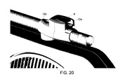
- FIG. 20 is an illustration of another perspective view of the assembled side clip 12 shown in FIG. 17 , installed on the vertical upper post 8 , in accordance with an example embodiment. Specifically, FIG. 20 shows the hinged tab 9 in the closed position, such that gripper 11 may be pressed against post 8 , thereby locking the clip 12 in a fixed position on post 8 .
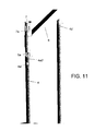
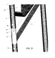
- FIG. 21 is an illustration of a vertical upper post 8 being installed on a support bar 6 , in accordance with an example embodiment.
- FIG. 21 shows aperture 8 a and depressible stop 7 a aligning with each other, and notch 8 b and physical stop 7 b aligning with each other.
- FIG. 22 is an illustration of an exploded view of an unassembled stand 10 , in accordance with an example embodiment.
- FIG. 22 shows the orientation of the pieces of the stand 10 that are described in detail in FIGS. 1-21 , where the major pieces of the stand include: base 2 with stubs 3 , lower posts 4 , support bar 6 with lower and upper stubs 5 / 7 , lower and upper portions 12 b / 12 a of clip 12 , upper posts 8 and stoppers 14 .
- the clips 12 may be attached to the fan 20 by a technician prior to a sale of the stand 10 , such that the remaining assembly of the stand 10 may be accomplished manually by an end user without the use of any tools.
- FIG. 23 is an illustration of a side view of an assembled stand 10 , in accordance with an example embodiment.
- the stand 10 of FIG. 23 shows many of the components of FIGS. 1-22 in an assembled state, and because these components have already been described, they are therefore not described again here, for brevity sake.
Abstract
The stand may be manually assembled without requiring tools. Two-points of contact are made between a horizontal support bar and respective upper and lower vertical posts in order to help resist vibration of the stand and the fan. Side clips are used to hold the fan. The side clips are slideable along a longitudinal length of the upper vertical posts. The side clips selectively grip the upper vertical posts at positions along a longitudinal length of the posts.
Description
- This application is a non-provisional application that claims priority to U.S. provisional application No. 62/173,622, filed on Jun. 10, 2015, the entire contents of which is incorporated by reference in its entirety.
- Example embodiments relate generally to a stand capable of being assembled without tools. More particularly, example embodiments relate to a stand that horizontally and vertically stabilizes a motorized device, such as a fan, that may experience vibration while in use.
- Conventionally, consumer products such as a motorized fan that may be purchased in a box often require some amount of assembly or setup in order to operate the product. Such products often times requires the use of a screwdriver, a hex key (Allen wrench), a conventional wrench, a ratchet set, or other tools that may or may not be provided with the product in order to fully assembly and use the product. Invariably, the end consumer may not have the tools necessary to assembly the product. Or, in order to assist the consumer, tools may be shipped with the product, thereby increasing the overall manufacturing cost and sale cost of the product.
- At least one example embodiments relates to a kit for a stand holding an electronic device.
- In one embodiment, the kit includes at least a first and a second lower vertical post; a horizontal support bar with at least a first and a second lower vertical stub and at least a first and second upper vertical stub, a first end of each of the lower vertical posts being connectable to the respective first and second lower vertical stubs via at least two points of contact; at least a first and a second upper vertical post, a first end of each of the upper vertical posts being connectable to the respective first and second upper vertical stubs via at least two points of contact; and a first and a second side clip, each of the side clips being connected to the electronic device, the side clips being configured to slide onto the respective first and second upper vertical posts, the side clips being configured to selectively grip the respective first and second upper vertical posts at positions along a longitudinal length of the respective first and second upper vertical posts, wherein the kit is configured to be assembled into the stand without requiring tools.
- In one embodiment, the kit further includes a base with at least a first and a second bottom vertical stub, a second end of each of the lower vertical posts being connectable to the respective first and second bottom vertical stubs of the base via at least two points of contact.
- In one embodiment, the first end of each of the lower vertical posts define a lower aperture and a lower notch that are respectively mateable with a lower depressible stop and a lower physical stop on each of the lower vertical stubs of the horizontal support bar to provide the two points of contact for the connection between the lower vertical stubs of the horizontal support bar and the lower vertical posts.
- In one embodiment, the second end of each of the lower vertical posts defines a bottom aperture and a bottom notch that are respectively mateable with a bottom depressible stop and a bottom physical stop on each of the bottom vertical stubs of the base to provide the two points of contact for the connection between the lower vertical posts and the bottom vertical stubs of the base.
- In one embodiment, the first end of each of the upper vertical posts defines an upper aperture and an upper notch that are respectively mateable with an upper depressible stop and an upper physical stop on each of the upper vertical stubs of the horizontal support bar to provide the two points of contact for the connection between the upper vertical posts and the upper vertical stubs of the horizontal support bar.
- In one embodiment, the lower and bottom apertures are on a same first side of the lower vertical posts, and the lower and bottom notches are on a same second side of the lower vertical posts, wherein the apertures and notches of the lower vertical posts are respectively offset from each other by about 180 degrees along a circumference of each of the respective lower vertical posts.
- In one embodiment, the bottom vertical stubs of the base are on opposing sides of the base, and the bottom depressible stops of the bottom vertical stubs are facing away from each other on opposing sides of the bottom vertical stubs, wherein the bottom physical stops of the bottom vertical stubs face each other on the bottom vertical stubs.
- In one embodiment, the upper and lower depressible stops and the upper physical stops of the respective upper and lower vertical stubs of the horizontal support bar are on a same first side of each of the respective upper and lower vertical stubs, wherein the lower physical stops are on opposing sides of the respective lower vertical stubs relative to a location of the lower depressible stops, the lower physical stops facing each other on the horizontal support bar.
- In one embodiment, the lower physical stops of the lower vertical stubs of the horizontal support bar are about 180 degrees offset from the lower depressible stops along a circumference of the lower vertical stubs.
- In one embodiment, the electronic device is a fan, wherein each of the side clips are connected to sides of the fan with a socket that allows a front of the fan to pivot in upward and downward angles.
- In one embodiment, each of the side clips include a hinged tab facing away from the fan, the hinged tabs of each of the side clips communicating with a gripper positioned along an inner surface of each of the respective side clips, each of the grippers being configured to selectively grip the respective first and second upper vertical posts via selective movement of the hinged tabs.
- In one embodiment, the lower vertical posts are longer than the upper vertical posts.
- At least one example embodiments relates to a stand that is capable of being assembled by a method that does not require tools.
- In one embodiment, the method includes depressing the bottom depressible stops of the bottom vertical stubs of the base and sliding the second ends of the first and second lower vertical posts onto the respective bottom vertical stubs so that the bottom physical stops mate with the bottom notches and the bottom depressible stops slide into the bottom apertures; depressing the lower depressible stops of the lower vertical stubs of the horizontal support bar and sliding the first ends of the first and second lower vertical posts onto the respective lower vertical stubs so that the lower physical stops mate with the upper notches and the lower depressible stops slide into the upper apertures; and depressing the upper depressible stops of the upper vertical stubs of the horizontal support bar and sliding the ends of the first and second upper vertical posts onto the respective upper vertical posts so that the upper physical stops mate with the lower notches and the upper depressible stops slide into the lower apertures.
- In one embodiment, the method further includes sliding the first and second side clips onto the respective first and second upper vertical posts; locking the electronic device into a desired vertical elevation along the first and second upper vertical posts using the side clips; and pressing stoppers on top of upper ends of the upper vertical posts.
- At least one example embodiment relates to a stand.
- In one embodiment, the stand includes a horizontal support bar; at least a first and second lower vertical post, a first end of each of the lower vertical posts being connected to lower vertical stubs on a lower portion of the horizontal support bar via at least two points of contact; at least a first and second upper vertical post, a first end of each of the upper vertical posts being connected to upper vertical stubs on an upper portion of the horizontal support bar via at least two points of contact; a first and a second side clip, each of the side clips being connected to an electronic device to hold the electronic device between the upper vertical posts, each of the side clips being configured to selectively grip one of the first and second upper vertical posts at positions along a longitudinal length of the respective upper vertical posts, wherein the stand is configured to be assembled without requiring tools.
- In one embodiment, the stand further includes a base, wherein a second end of each of the lower vertical posts being connected to bottom vertical stubs on the base via at least two points of contact.
- In one embodiment, each of the vertical stubs includes at least two of a physical stop and a depressible stop, and each of the first and second ends of the lower vertical posts, and each of the first ends of the upper vertical posts, defines at least two of a notch and an aperture that are mateable with the respective physical stops and depressible stops of the vertical stubs to provide the two points of contact.
- In one embodiment, each of the vertical stubs includes a physical stop and a depressible stop, the upper vertical stubs of the horizontal support bar having an upper depressible stop and an upper physical stop on a same side of the upper vertical stubs.
- In one embodiment, the lower vertical stubs of the horizontal support bar, and the bottom vertical stubs of the base, each have a lower depressible stop and a lower physical stop on opposing sides of the respective lower and bottom stubs, the respective lower and bottom physical stops of the lower and bottom vertical stubs facing inward toward each other.
- In one embodiment, the electronic device is a fan, each of the side clips being connected to sides of the fan via a socket that allows a front of the fan to pivot in upward and downward angles, the side clips including a hinged tab facing away from the fan and being in communication with a gripper positioned along an inner surface of each of the side clips, the gripper being configured to selectively grip the respective first and second upper vertical posts.
- The above and other features and advantages of example embodiments will become more apparent by describing in detail, example embodiments with reference to the attached drawings. The accompanying drawings are intended to depict example embodiments and should not be interpreted to limit the intended scope of the claims. The accompanying drawings are not to be considered as drawn to scale unless explicitly noted.
-
FIG. 1 is an illustration of a perspective view of an assembled stand, in accordance with an example embodiment; -
FIG. 2 is an illustration of a perspective view of an assembled stand, holding a fan, in accordance with an example embodiment; -
FIG. 3 is an illustration of a perspective view of a base of a stand, in accordance with an example embodiment; -
FIG. 4 is an illustration of a side view of the base of the stand shown inFIG. 3 , in accordance with an example embodiment; -
FIG. 5 is an illustration of a perspective view of a vertical lower post for a stand, in accordance with an example embodiment; -
FIG. 6 is an illustration of a side view of the vertical lower post shown inFIG. 5 , in accordance with an example embodiment; -
FIG. 7 is an illustration of a vertical lower post being installed on a base of a stand, in accordance with an example embodiment; -
FIG. 8 is another illustration of another perspective of the vertical lower post being installed on the base of the stand shown inFIG. 7 , in accordance with an example embodiment; -
FIG. 9 is an illustration of a perspective view of a support bar of a stand, in accordance with an example embodiment; -
FIG. 10 is an illustration of a side view of the support bar shown inFIG. 9 , in accordance with an example embodiment; -
FIG. 11 is an illustration of the support bar shown inFIG. 9 being installed on a vertical lower post, in accordance with an example embodiment; -
FIG. 12 is an illustration of a side view of a vertical upper post of a stand, in accordance with an example embodiment; -
FIG. 13 is an illustration of a lower portion of a side clip of a stand, in accordance with an example embodiment; -
FIG. 14 is an illustration of an upper portion of a side clip of a stand, in accordance with an example embodiment; -
FIG. 15 is an illustration of a perspective view of the upper portion and lower portion ofFIGS. 13 and 14 being connected together, in accordance with an example embodiment; -
FIG. 16 illustrates an illustration of a side view of the upper portion and lower portion ofFIGS. 13 and 14 , in accordance with an example embodiment; -
FIG. 17 is an illustration of a perspective view of an assembled side clip of a stand, in accordance with an example embodiment; -
FIG. 18 is an illustration of another perspective view of the assembled side clip shown inFIG. 17 , in accordance with an example embodiment; -
FIG. 19 is an illustration of a perspective view of the assembled side clip shown inFIG. 17 , installed on a vertical upper post, in accordance with an example embodiment; -
FIG. 20 is an illustration of another perspective view of the assembled side clip shown inFIG. 17 , installed on the vertical upper post, in accordance with an example embodiment; -
FIG. 21 is an illustration of a vertical upper post being installed on a support bar, in accordance with an example embodiment; -
FIG. 22 is an illustration of an exploded view of an unassembled stand, in accordance with an example embodiment; and -
FIG. 23 is an illustration of a side view of an assembled stand, in accordance with an example embodiment. - Detailed example embodiments are disclosed herein. However, specific structural and functional details disclosed herein are merely representative for purposes of describing example embodiments. Example embodiments may, however, be embodied in many alternate forms and should not be construed as limited to only the embodiments set forth herein.
- Accordingly, while example embodiments are capable of various modifications and alternative forms, embodiments thereof are shown by way of example in the drawings and will herein be described in detail. It should be understood, however, that there is no intent to limit example embodiments to the particular forms disclosed, but to the contrary, example embodiments are to cover all modifications, equivalents, and alternatives falling within the scope of example embodiments. Like numbers refer to like elements throughout the description of the figures.
- It will be understood that, although the terms first, second, etc. may be used herein to describe various elements, these elements should not be limited by these terms. These terms are only used to distinguish one element from another. For example, a first element could be termed a second element, and, similarly, a second element could be termed a first element, without departing from the scope of example embodiments. As used herein, the term “and/or” includes any and all combinations of one or more of the associated listed items.
- It will be understood that when an element is referred to as being “connected” or “coupled” to another element, it may be directly connected or coupled to the other element or intervening elements may be present. In contrast, when an element is referred to as being “directly connected” or “directly coupled” to another element, there are no intervening elements present. Other words used to describe the relationship between elements should be interpreted in a like fashion (e.g., “between” versus “directly between”, “adjacent” versus “directly adjacent”, etc.).
- The terminology used herein is for the purpose of describing particular embodiments only and is not intended to be limiting of example embodiments. As used herein, the singular forms “a”, “an” and “the” are intended to include the plural forms as well, unless the context clearly indicates otherwise. It will be further understood that the terms “comprises”, “comprising,”, “includes” and/or “including”, when used herein, specify the presence of stated features, integers, steps, operations, elements, and/or components, but do not preclude the presence or addition of one or more other features, integers, steps, operations, elements, components, and/or groups thereof.
- It should also be noted that in some alternative implementations, the functions/acts noted may occur out of the order noted in the figures. For example, two figures shown in succession may in fact be executed substantially concurrently or may sometimes be executed in the reverse order, depending upon the functionality/acts involved.
-
FIG. 1 is an illustration of a perspective view of an assembledstand 10, in accordance with an example embodiment. Thestand 10 may include asupportive base 2 that may be wide enough to potentially withstand vibration while thestand 10 is in use. Thestand 10 may also include verticallower posts 4 connected to thebase 2. While two verticallower posts 4 are shown in this example embodiment, it should be understood that one verticallower post 4 may be used rather than two posts 4 (not shown). Alternatively, more than twoposts 4 may also be used (not shown). - A
support bar 6 may be used to hold a top portion f the verticallower posts 4 together, in order to stabilize thestand 10, especially in the event that thestand 10 may experience vibration while in use. It should be understood that asupport bar 6 would not be utilized in the event that only a singlelower post 4 is used. Furthermore, in the event that more than twolower posts 4 are used for thestand 10, asingle support bar 6 may be used to connect a top portion of each of the lower posts together (not shown). Alternatively, in the event that more than twolower posts 4 are used for thestand 10, more than onesupport bar 6 may be used to connect thelower posts 4 to each other. For instance, in an alternative embodiment, asingle support bar 6 may be used to connect two (or more)lower posts 4 to each other, such thatmultiple support bars 6 may then be used in order to ultimately connect eachlower post 4 to another adjacentlower post 4. For example, using a stand configuration with threelower posts 4, two or threesupport bars 6 may be used to connect eachlower post 4 to at least one other adjacent lower post 4 (not shown). - Vertical
upper posts 8 may be connected to thesupport bar 6. In the example embodiment ofFIG. 1 , twoupper posts 8 are shown. However, in a stand configuration with only one verticallower post 4, only a singleupper post 8 may be used. Alternatively, in the event that more than twolower posts 4 for thestand 10, more than twoupper posts 8 may also be used to add extra support and stability to thestand 10. - Side clips 12 (shown in more detail in
FIGS. 13-18 ) may be included on theupper posts 8. Theclips 12 may be used to hold a fan 20 (for instance) between the upper posts 8 (see this shown inFIG. 2 ). In an alternative embodiment, if only oneupper post 8 is used for thestand 10, or if more than twoupper posts 8 are used for thestand 10, a number of side clips 12 may equal a number ofupper posts 8. In another alternative embodiment, the side clips may be attached to thelower posts 4, such that thestand 10 may not includeupper posts 8. -
Stoppers 14 may be fitted onto a top end of theupper posts 8. -
FIG. 2 is an illustration of a perspective view of an assembledstand 10 a, holding afan 20, in accordance with an example embodiment. In particular, the clips may connect to side surfaces of thefan 20 in order to securely hold the fan between theupper posts 8 of thestand 10 a (that includes the fan 20). - In order to provide the
stand 10 a with greater stability, a length of theupper posts 8 may be approximately equal to a length of thefan 20. This will allow thesupport bar 6 to be positioned relatively close to thefan 20 itself, in order for the overall stability of thestand 10 a to be improved in holding thefan 20, especially in the event that thefan 20 may be expected to produce some amount of vibration while in use. - It is further noted that the
lower posts 4 may be slightly longer than theupper posts 8. In such a configuration, an overall height of thestand 10 a may be increased, while still affording a high degree of stability for thestand 10 a, as the use of relatively shorterupper posts 8 may more firmly grip the sides of the fan 20 (i.e., the portion of thestand 10 a located closest to a source of vibration), even if an overall height of thestand 10 a is significantly taller than thefan 20 height. - In order to add further stability to the stand 10 a as a whole, a
width 2 a portion of the base 2 (which runs about perpendicular to alength 2 b of thebase 2 spanning between the lower posts 4) may extend away from the lower posts 4. Furthermore, while thebase 2 shown inFIGS. 1-4 has a somewhat rectangular footprint (with thewidth 2 a being somewhat shorter than thelength 2 b), it should be understood that a somewhat square footprint may also be utilized. Alternatively, a circular or triangular-shaped footprint (or, another shape) may also be utilized for thebase 2. - While
FIG. 2 shows thestand 10 a holding afan 20, it should be understood that thestand 10 a may alternatively hold another device besides a fan. -
FIG. 3 is an illustration of a perspective view of a base of astand 2, in accordance with an example embodiment. Thestand 2 may include one or morevertical stubs 3 connected to a top portion of thebase 2. Each of thevertical stubs 3 may include one or more stops. For instance, eachstub 3 may include aphysical stop 3 b, which may be positioned near a juncture between thestub 3 and a top portion of the base (shown in more detail inFIG. 4 ). Eachstub 3 may also include adepressible stop 3 a (also shown inFIG. 4 ). Thedepressible stop 3 a may be configured to allow an end user to depress an outer surface of thestop 3 a so that a portion of alower post 4 may clear thestop 3 a (shown in better detail inFIG. 7 ). -
FIG. 4 is an illustration of a side view of thebase 2 shown inFIG. 3 , in accordance with an example embodiment. Notice that thedepressible stop 3 a and thephysical stop 3 b may be located on opposite sides of each stub 3 (such that thedepressible stop 3 a and thephysical stop 3 b are positioned about 180 degrees apart from each other on an outer surface of each stub 3). Alternatively, thedepressible stop 3 a and thephysical stop 3 b may be positioned on a same side of eachstub 3. Or, thedepressible stub 3 a and thephysical stop 3 b may be spaced apart along an outer surface of thestub 3 using a different spacing than shown inFIG. 4 (such as 90 degrees apart, or 45 degrees, for example). -
FIG. 5 is an illustration of a perspective view of a verticallower post 4 for astand 10, in accordance with an example embodiment. Thelower post 4 may include one or more notches or apertures. For instance, thelower post 4 may include anupper notch 4 b′ and anupper aperture 4 a′ located near a top portion of thelower post 4. An identicallower notch 4 b (shown inFIG. 6 ) andlower aperture 4 a may also be located near a bottom portion of thelower post 4. Thelower notch 4 b may be mateable with thephysical stop 3 b of thebase 2. Thelower aperture 4 a may be mateable with thedepressible stop 3 a and thebase 2. Meanwhile, theupper notch 4 b′ andupper aperture 4 a′ may be respectively mateable with a lowerphysical stop 5 b and lowerdepressible stop 5 a of a support bar 6 (seeFIGS. 9-11 ). -
FIG. 6 is an illustration of a side view of the verticallower post 4 shown inFIG. 5 , in accordance with an example embodiment.FIG. 6 shows in better detail the location of thenotches 4 b/4 b′ andapertures 4 a/4 a′ that may be included on thepost 4. -
FIG. 7 is an illustration of a verticallower post 4 being installed on abase 2 of astand 10, in accordance with an example embodiment. In particular,FIG. 7 shows an alignment of thedepressible stop 3 a (on stub 3) withlower aperture 4 a of thelower post 4. Thedepressible stop 3 a may include anangled portion 3 a 1 that may allow anend 4 a 1 of thelower post 4 to slide over thedepressible stop 3 a, such that theend portion 4 a 1 of thepost 4 may force thedepressible stop 3 a to be pressed inwards within thepost 4. Once the lower post is fully pressed down ontostub 3, thedepressible stop 3 a may flare outward, so that thestop 3 a may fill theaperture 4 a. Alower edge 3 a 2 of thestop 2 a may retard the lower post from being inadvertently separated frombase 2. However, an end user may press thedepressible stop 3 a in order to allow thestop 3 a to clear thelower portion 4 a 1 of thelower post 4 in order to intentionally remove thelower post 4 from the base 2 (during disassembly of thestand 10, for instance). -
FIG. 8 is another illustration of another perspective of the verticallower post 4 being installed on thebase 2 of thestand 10 shown inFIG. 7 , in accordance with an example embodiment. In particular,FIG. 8 shows an alignment betweenlower notch 4 a andphysical stop 3 b as thelower post 4 is fitted ontobase 2. The mating of thephysical stop 3 b withnotch 4 a, and the mating ofdepressible stop 3 a withaperture 4 a, may act as a two-point contact that allowspost 4 to resist rotation whilepost 4 is fitted ontobase 2. In an alternative embodiment, thepost 4 may include only anaperture 4 a that is mateable withdepressible stop 3 a (devoid ofnotch 4 a andphysical stop 3 b). Likewise, more apertures or more notches may alternatively be included on an end ofpost 4, which may be mateable with respective physical stops or depressible stops. -
FIG. 9 is an illustration of a perspective view of asupport bar 6 of a stand, in accordance with an example embodiment. Thesupport bar 6 may include verticallower stubs 5 and verticalupper stubs 7. Thelower stubs 5 may each include a lowerphysical stop 5 b and a lowerdepressible stop 5 a on an outer surface of thestubs 5. Similar to thestubs 3 ofbase 2, the position of the lowerphysical stops 5 b and lower depressible stops 5 a may vary (although the lowerphysical stops 5 b and lower depressible stops 5 a are shown to be 180 degrees apart from each other, on an outer surface ofstubs 5, in the example embodiment ofFIG. 9 ). -
FIG. 10 is an illustration of a side view of thesupport bar 6 shown inFIG. 9 , in accordance with an example embodiment. In particular,FIG. 10 shows in better detail, the positions of the lowerdepressible stop 5 a, the lowerphysical stop 5 b, the upperdepressible stop 7 a, and the upperphysical stop 7 b. As indicated above, the precise positions of the depressible stops and physical stops may change. Additionally, as indicated above, only depressible stops may be used, such that the physical stops may be excluded. Alternatively, more depressible stops, or more physical stops, may also be used. However, it should be understood that, by using a pairing of a physical stop with a depressible stop for eachstub 5/7, therespective posts 4/8 will be less prone to twisting, as the two points of contact will add a degree of stability and vibration resistance that may assist the overall performance of thestand 10. -
FIG. 11 is an illustration of thesupport bar 6 shown inFIG. 9 being installed on a verticallower post 4, in accordance with an example embodiment. In particular, lowerdepressible stop 5 a may align with theupper aperture 4 a′ ofpost 4, just asupper notch 4 b′ may also align with lowerphysical stop 5 b. As described with regard toFIG. 7 (above), thedepressible stop 5 a may allow anupper portion 4 a 2′ to clear thestop 5 a, and once thesupport bar 6 is firmly pressed onto thelower post 4, thestop 5 a may projected throughaperture 4 a′ to causesupport bar 6 to be physically secured to post 4. -
FIG. 12 is an illustration of a side view of a verticalupper post 8 of astand 10, in accordance with an example embodiment. Theupper post 8 may be similar tolower post 4, with the exception thatlower apertures 8 a andlower notch 8 b may be on a same side ofpost 8, whereas theupper aperture 8 a′ andupper notch 8 b′ may also be on a same side ofpost 8, although theaperture 8 a′ andnotch 8 b′ may be on an opposite side of thepost 8 as compared toaperture 8 a andnotch 8 b. -
FIG. 13 is an illustration of alower portion 12 a of aside clip 12 of astand 10, in accordance with an example embodiment. The lower portion may include onemore prongs 12 a 1/12 a 2 that may be mateable withholes 12 b 1/12 b 2 (or recesses) of anupper portion 12 b of the side clip 12 (see theupper portion 12 b inFIG. 14 ). Theprongs 12 a 1/12 a 2 and holes 12 b 1/12b 2 may be utilized to help thelower portion 12 a and theupper portion 12 b of theclip 12 stay connected together while in use. Other means of connecting thelower portion 12 a andupper portion 12 b of the clip together, such as clips, snap-fit components, frictional couplings, etc., may also be utilized. - A
bolt hole 12 a 4 running clear-through thelower portion 12 a may be provided in order to bolt thelower portion 12 a directly to the fan. -
FIG. 14 is an illustration of anupper portion 12 b of aside clip 12 of astand 10, in accordance with an example embodiment. The upper portion may include asocket 12b 3, or other comparable structure, that may be used to connect theupper portion 12 b of theclip 12 to the side surface of thefan 20. Therefore, theclip 12 may be connected to thefan 20 via two points of contact: 1) thesocket 12b 3 connectingupper portion 12 b to thefan 20, and 2) a bolt running thoughbolt hole 12 a 4 connectinglower portion 12 a to thefan 20. -
FIG. 15 is an illustration of a perspective view of theupper portion 12 b andlower portion 12 a ofFIGS. 13 and 14 being connected together, in accordance with an example embodiment. Abeveled edge 12b 4 of theupper portion 12 b may be provided in order to frictionally fit within anupper lip 12 a 3 of thelower portion 12 a in order to further secure theportions 12 a/12 b to each other. -
FIG. 16 illustrates a side view of theupper portion 12 b andlower portion 12 a of aFIGS. 13 and 14 , in accordance with an example embodiment. In particular,FIG. 16 shows socket 12b 3 of theupper portion 12 b in better detail, where asocket hole 12b 3 a may be provided to engage a spindle (not shown) connected to thefan 20. Thesocket 12b 3 may be configured to allow thefan 20 to pivot between opposing clips 12 (seeFIG. 2 ) connected to theupper posts 8, so that the fan may be pivoted to face a more upward angle or a more downward angle based on an end user preference. -
FIG. 17 is an illustration of a perspective view of an assembledside clip 12 of astand 10, in accordance with an example embodiment. Ahole 12 a 5 through thelower portion 12 a of theclip 12, and arespective hole 12b 5 through theupper portion 12 b of theclip 12, may be included in order to allow theclip 12 to fit onto upper posts 8 (see at leastFIG. 19 ). A hingedtab 9 may be included at a juncture between thelower portion 12 a and theupper portion 12 b of theclip 12. A gripper may also be positioned at an inner juncture between thelower portion 12 a and theupper portion 12 b of theclip 12. The hingedtab 9 andgripper 11 may be operably connected to each other, such that thegripper 11 may be forced slightly downward (i.e., toward a center-line of theholes 12 a 5/12 b 5) when thetab 9 is in a closed position (seeFIG. 18 ), so that thegripper 11 may press and grip a side surface of thepost 8 to lockclip 12 onto thepost 8. -
FIG. 18 is an illustration of another perspective view of the assembledside clip 12 shown inFIG. 15 , in accordance with an example embodiment. InFIG. 18 , the hingedtab 9 is in the closed position. As described above, in the closed position,tab 9 may be configured to cause the gripper to be forced slightly downward in order to press againupper post 8 when theclip 12 is installed on thepost 8. -
FIG. 19 is an illustration of a perspective view of the assembledside clip 12 shown inFIG. 15 , installed on a verticalupper post 8, in accordance with an example embodiment. Specifically,FIG. 19 shows the hingedtab 9 in an opened position. In this position, the gripper (FIG. 18 ) is slightly retracted, allowing theclip 12 to slide alongpost 8. This may allow thefan 20 to be shifted upwards or downwards on the opposing posts 8 (FIG. 2 ) in order to adjust the height of thefan 20 relative to the ground. -
FIG. 20 is an illustration of another perspective view of the assembledside clip 12 shown inFIG. 17 , installed on the verticalupper post 8, in accordance with an example embodiment. Specifically,FIG. 20 shows the hingedtab 9 in the closed position, such thatgripper 11 may be pressed againstpost 8, thereby locking theclip 12 in a fixed position onpost 8. -
FIG. 21 is an illustration of a verticalupper post 8 being installed on asupport bar 6, in accordance with an example embodiment. In particular,FIG. 21 shows aperture 8 a anddepressible stop 7 a aligning with each other, and notch 8 b andphysical stop 7 b aligning with each other. -
FIG. 22 is an illustration of an exploded view of anunassembled stand 10, in accordance with an example embodiment. In particular,FIG. 22 shows the orientation of the pieces of thestand 10 that are described in detail inFIGS. 1-21 , where the major pieces of the stand include:base 2 withstubs 3,lower posts 4,support bar 6 with lower andupper stubs 5/7, lower andupper portions 12 b/12 a ofclip 12,upper posts 8 andstoppers 14. Because the upper andlower portions 12 b/12 a ofclip 12 may require bolts to affix theclip 12 to the fan, theclips 12 may be attached to thefan 20 by a technician prior to a sale of thestand 10, such that the remaining assembly of thestand 10 may be accomplished manually by an end user without the use of any tools. -
FIG. 23 is an illustration of a side view of an assembledstand 10, in accordance with an example embodiment. Thestand 10 ofFIG. 23 shows many of the components ofFIGS. 1-22 in an assembled state, and because these components have already been described, they are therefore not described again here, for brevity sake. - Example embodiments having thus been described, it will be obvious that the same may be varied in many ways. Such variations are not to be regarded as a departure from the intended spirit and scope of example embodiments, and all such modifications as would be obvious to one skilled in the art are intended to be included within the scope of the following claims.
Claims (20)
1. A kit for a stand holding an electronic device, comprising:
at least a first and a second lower vertical post;
a horizontal support bar with at least a first and a second lower vertical stub and at least a first and second upper vertical stub, a first end of each of the lower vertical posts being connectable to the respective first and second lower vertical stubs via at least two points of contact;
at least a first and a second upper vertical post, a first end of each of the upper vertical posts being connectable to the respective first and second upper vertical stubs via at least two points of contact; and
a first and a second side clip, each of the side clips being connected to the electronic device, the side clips being configured to slide onto the respective first and second upper vertical posts, the side clips being configured to selectively grip the respective first and second upper vertical posts at positions along a longitudinal length of the respective first and second upper vertical posts,
wherein the kit is configured to be assembled into the stand without requiring tools.
2. The kit of claim 1 , further comprising:
a base with at least a first and a second bottom vertical stub, a second end of each of the lower vertical posts being connectable to the respective first and second bottom vertical stubs of the base via at least two points of contact.
3. The kit of claim 2 , wherein the first end of each of the lower vertical posts define a lower aperture and a lower notch that are respectively mateable with a lower depressible stop and a lower physical stop on each of the lower vertical stubs of the horizontal support bar to provide the two points of contact for the connection between the lower vertical stubs of the horizontal support bar and the lower vertical posts.
4. The kit of claim 3 , wherein the second end of each of the lower vertical posts defines a bottom aperture and a bottom notch that are respectively mateable with a bottom depressible stop and a bottom physical stop on each of the bottom vertical stubs of the base to provide the two points of contact for the connection between the lower vertical posts and the bottom vertical stubs of the base.
5. The kit of claim 4 , wherein the first end of each of the upper vertical posts defines an upper aperture and an upper notch that are respectively mateable with an upper depressible stop and an upper physical stop on each of the upper vertical stubs of the horizontal support bar to provide the two points of contact for the connection between the upper vertical posts and the upper vertical stubs of the horizontal support bar.
6. The kit of claim 5 , wherein the lower and bottom apertures are on a same first side of the lower vertical posts, and the lower and bottom notches are on a same second side of the lower vertical posts, wherein the apertures and notches of the lower vertical posts are respectively offset from each other by about 180 degrees along a circumference of each of the respective lower vertical posts.
7. The kit of claim 5 , wherein the bottom vertical stubs of the base are on opposing sides of the base, and the bottom depressible stops of the bottom vertical stubs are facing away from each other on opposing sides of the bottom vertical stubs, wherein the bottom physical stops of the bottom vertical stubs face each other on the bottom vertical stubs.
8. The kit of claim 5 , wherein the upper and lower depressible stops and the upper physical stops of the respective upper and lower vertical stubs of the horizontal support bar are on a same first side of each of the respective upper and lower vertical stubs, wherein the lower physical stops are on opposing sides of the respective lower vertical stubs relative to a location of the lower depressible stops, the lower physical stops facing each other on the horizontal support bar.
9. The kit of claim 8 , wherein the lower physical stops of the lower vertical stubs of the horizontal support bar are about 180 degrees offset from the lower depressible stops along a circumference of the lower vertical stubs.
10. The kit of claim 2 , wherein the electronic device is a fan, wherein each of the side clips are connected to sides of the fan with a socket that allows a front of the fan to pivot in upward and downward angles.
11. The kit of claim 2 , wherein each of the side clips include a hinged tab facing away from the fan, the hinged tabs of each of the side clips communicating with a gripper positioned along an inner surface of each of the respective side clips, each of the grippers being configured to selectively grip the respective first and second upper vertical posts via selective movement of the hinged tabs.
12. The kit of claim 2 , wherein the lower vertical posts are longer than the upper vertical posts.
13. A stand that is capable of being assembled by a method that does not require tools, the method utilizing the kit of claim 5 , the method comprising:
depressing the bottom depressible stops of the bottom vertical stubs of the base and sliding the second ends of the first and second lower vertical posts onto the respective bottom vertical stubs so that the bottom physical stops mate with the bottom notches and the bottom depressible stops slide into the bottom apertures;
depressing the lower depressible stops of the lower vertical stubs of the horizontal support bar and sliding the first ends of the first and second lower vertical posts onto the respective lower vertical stubs so that the lower physical stops mate with the upper notches and the lower depressible stops slide into the upper apertures; and
depressing the upper depressible stops of the upper vertical stubs of the horizontal support bar and sliding the ends of the first and second upper vertical posts onto the respective upper vertical posts so that the upper physical stops mate with the lower notches and the upper depressible stops slide into the lower apertures.
14. The method of claim 13 , further comprising:
sliding the first and second side clips onto the respective first and second upper vertical posts;
locking the electronic device into a desired vertical elevation along the first and second upper vertical posts using the side clips; and
pressing stoppers on top of upper ends of the upper vertical posts.
15. A stand, comprising:
a horizontal support bar;
at least a first and second lower vertical post, a first end of each of the lower vertical posts being connected to lower vertical stubs on a lower portion of the horizontal support bar via at least two points of contact;
at least a first and second upper vertical post, a first end of each of the upper vertical posts being connected to upper vertical stubs on an upper portion of the horizontal support bar via at least two points of contact;
a first and a second side clip, each of the side clips being connected to an electronic device to hold the electronic device between the upper vertical posts, each of the side clips being configured to selectively grip one of the first and second upper vertical posts at positions along a longitudinal length of the respective upper vertical posts,
wherein the stand is configured to be assembled without requiring tools.
16. The stand of claim 15 , further comprising:
a base, wherein a second end of each of the lower vertical posts being connected to bottom vertical stubs on the base via at least two points of contact.
17. The stand of claim 16 , wherein each of the vertical stubs includes at least two of a physical stop and a depressible stop, and each of the first and second ends of the lower vertical posts, and each of the first ends of the upper vertical posts, defines at least two of a notch and an aperture that are mateable with the respective physical stops and depressible stops of the vertical stubs to provide the two points of contact.
18. The stand of claim 17 , wherein each of the vertical stubs includes a physical stop and a depressible stop, the upper vertical stubs of the horizontal support bar having an upper depressible stop and an upper physical stop on a same side of the upper vertical stubs.
19. The stand of claim 18 , wherein the lower vertical stubs of the horizontal support bar, and the bottom vertical stub of the base, each have a lower depressible stop and a lower physical stop on opposing sides of the respective lower and bottom stubs, the respective lower and bottom physical stops of the lower and bottom vertical stubs facing inward toward each other.
20. The stand of claim 15 , wherein the electronic device is a fan, each of the side clips being connected to sides of the fan via a socket that allows a front of the fan to pivot in upward and downward angles, the side clips including a hinged tab facing away from the fan and being in communication with a gripper positioned along an inner surface of each of the side clips, the gripper being configured to selectively grip the respective first and second upper vertical posts.
Priority Applications (1)
| Application Number | Priority Date | Filing Date | Title |
|---|---|---|---|
| US15/177,952 US9926945B2 (en) | 2015-06-10 | 2016-06-09 | Snap-together stand for a fan |
Applications Claiming Priority (2)
| Application Number | Priority Date | Filing Date | Title |
|---|---|---|---|
| US201562173622P | 2015-06-10 | 2015-06-10 | |
| US15/177,952 US9926945B2 (en) | 2015-06-10 | 2016-06-09 | Snap-together stand for a fan |
Publications (2)
| Publication Number | Publication Date |
|---|---|
| US20160363256A1 true US20160363256A1 (en) | 2016-12-15 |
| US9926945B2 US9926945B2 (en) | 2018-03-27 |
Family
ID=57516476
Family Applications (1)
| Application Number | Title | Priority Date | Filing Date |
|---|---|---|---|
| US15/177,952 Active US9926945B2 (en) | 2015-06-10 | 2016-06-09 | Snap-together stand for a fan |
Country Status (1)
| Country | Link |
|---|---|
| US (1) | US9926945B2 (en) |
Cited By (1)
| Publication number | Priority date | Publication date | Assignee | Title |
|---|---|---|---|---|
| WO2022192778A1 (en) * | 2021-03-12 | 2022-09-15 | Milwaukee Electric Tool Corporation | Fan assembly |
Families Citing this family (2)
| Publication number | Priority date | Publication date | Assignee | Title |
|---|---|---|---|---|
| JP1679572S (en) * | 2020-03-20 | 2021-02-22 | ||
| US11268539B2 (en) * | 2020-05-12 | 2022-03-08 | Chia-Yuan Liu | Fan device and fan holder |
Citations (55)
| Publication number | Priority date | Publication date | Assignee | Title |
|---|---|---|---|---|
| US1587090A (en) * | 1925-12-28 | 1926-06-01 | Tweed Clarence Melvin | Combined barrel lift and stand |
| US2110158A (en) * | 1936-01-06 | 1938-03-08 | Georgina G Keeler | Coat and garment hanger |
| US2521920A (en) * | 1947-03-13 | 1950-09-12 | Westinghouse Electric Corp | Air translating apparatus support |
| US2598529A (en) * | 1948-12-07 | 1952-05-27 | Karl J Fritz | Universally adjustable support for X-ray cassettes |
| US2767003A (en) * | 1948-06-22 | 1956-10-16 | Emil Greiner Company | Joint for universally adjustable frame |
| US2868558A (en) * | 1957-07-09 | 1959-01-13 | Krauss Carl | Roll-about stand for fans and similar appliances |
| US2958110A (en) * | 1956-07-09 | 1960-11-01 | Roger W Mcbrien | Laboratory clamp |
| US3117760A (en) * | 1960-03-31 | 1964-01-14 | Robert A Dresbach | Support for a portable and collapsible exercising device |
| US3404884A (en) * | 1965-09-27 | 1968-10-08 | New American Co Inc | Balance beam adapter for gymnastic apparatus transporters |
| US3405894A (en) * | 1967-07-31 | 1968-10-15 | Vernco Corp | Fan housing level holding structure |
| US4790500A (en) * | 1986-08-26 | 1988-12-13 | Kei Mori | Optical conductor cable supporting stand for a light ray radiation device used in medical treatment |
| US4934015A (en) * | 1988-12-12 | 1990-06-19 | Mink Jerry C | Mini-blind cleaning rack apparatus |
| US5370500A (en) * | 1994-03-14 | 1994-12-06 | Thompson; Jerry E. | Oscillating fan support |
| US5501544A (en) * | 1994-11-10 | 1996-03-26 | Nolu Plastics, Inc. | Three-piece clamping assembly |
| US5520293A (en) * | 1994-12-07 | 1996-05-28 | Hartley; Brenda G. | Double video game rack and control deck |
| US5769371A (en) * | 1995-06-09 | 1998-06-23 | Bandur; Kenneth B. | Adjustable leveling stand |
| US5987789A (en) * | 1998-03-09 | 1999-11-23 | Lubina; John R. | Stitchery stand and frame |
| US6116437A (en) * | 1997-12-03 | 2000-09-12 | Avilion Limited | Modular construction towel rack |
| US6223358B1 (en) * | 2000-01-05 | 2001-05-01 | Depietro Charles M. | Convertible pool cover support |
| US6226931B1 (en) * | 1999-06-04 | 2001-05-08 | Canfield Industries, Inc. | Modular display system |
| US20010019095A1 (en) * | 2001-03-21 | 2001-09-06 | Southern Imperial, Inc. | Stand base |
| WO2002018796A1 (en) * | 2000-08-31 | 2002-03-07 | Graves Spray Supply, Inc. | Adjustable impingement dual blower apparatus |
| US6390311B1 (en) * | 2000-07-31 | 2002-05-21 | Martin Paul, Inc. | Ambulatory dispenser rack |
| US6390424B1 (en) * | 2000-07-13 | 2002-05-21 | Margo Kidushim | Accessory support device and method |
| US6517043B1 (en) * | 2001-10-18 | 2003-02-11 | Emerson Electric Co. | Segmented fan base |
| US6550725B1 (en) * | 2002-02-04 | 2003-04-22 | Dale E. Watson | Adjustable fan stand |
| US20040104319A1 (en) * | 2002-02-27 | 2004-06-03 | Dean Douglas R. | Pole connector assembly and method for racks and shelving |
| US20040112854A1 (en) * | 2002-12-17 | 2004-06-17 | Kuo-Ping Lai | Detachable clothes rack |
| US6761274B1 (en) * | 2003-02-06 | 2004-07-13 | Ching-Fei Chen | Locating structure of expandable units of a rack |
| US6796446B2 (en) * | 2003-01-08 | 2004-09-28 | La-La Imports Lp | Shaft adjustment apparatus and method |
| US20040222179A1 (en) * | 2003-05-08 | 2004-11-11 | Rod Garcia | Modular rack system |
| US6817478B2 (en) * | 2001-05-31 | 2004-11-16 | Frank Venegas, Jr. | Modular office furniture |
| US6902071B2 (en) * | 2002-12-26 | 2005-06-07 | Steven J. Vitale | DVD-VCR-CD shelf storage system |
| US7077277B2 (en) * | 2004-09-27 | 2006-07-18 | Chi-Chung Wang | Foot assembly of a clothes rack |
| US20070163974A1 (en) * | 2006-01-17 | 2007-07-19 | Hsiu-Chen Lai | Clothes-hanging device |
| US7249680B2 (en) * | 2005-01-03 | 2007-07-31 | Chi Yu Steel Co., Ltd. | Shoe rack |
| US20080029473A1 (en) * | 2006-08-07 | 2008-02-07 | Cheng Wei Furniture Co., Ltd. | Clothes rack available for dustproof jacket |
| US20080149007A1 (en) * | 2006-12-20 | 2008-06-26 | Maclean Tim J | Connection system |
| US20080272252A1 (en) * | 2007-05-02 | 2008-11-06 | Joseph Conde | Stackable, modular and decorative bowl assembly |
| US7516590B2 (en) * | 2002-07-31 | 2009-04-14 | Scafom International B.V. | Modular heavy duty support system |
| US20100237027A1 (en) * | 2009-03-20 | 2010-09-23 | Illinois Tool Works Inc. | Bicycle Stand |
| US20100300998A1 (en) * | 2009-06-01 | 2010-12-02 | Christine Suzanne Plante | Single mini clothesline |
| US7850021B2 (en) * | 2008-02-05 | 2010-12-14 | Cheng-En Yang | Iron pipe furniture assembly structure |
| US7938372B2 (en) * | 2001-09-06 | 2011-05-10 | Mti Research Corporation | Free standing or vehicle mounted 6-axis positionable tray, positionable shelf, cup-holder, stanchion apparatus and related systems |
| US8042785B2 (en) * | 2006-10-19 | 2011-10-25 | Lucenti S.R.L. | Display stand |
| US8141723B2 (en) * | 2006-08-18 | 2012-03-27 | Plano Molding Company | Inverted cell honeycomb structure shelving |
| US20120138557A1 (en) * | 2009-08-17 | 2012-06-07 | Taeilmoldtech Co., Ltd. | Hanger with a stable stepwise folding function |
| US20140262659A1 (en) * | 2013-03-15 | 2014-09-18 | James F. Hirsch | Portable garment hanging system for a portable wardrobe bag |
| US20150008201A1 (en) * | 2013-07-02 | 2015-01-08 | Whitmor, Inc. | Folding garment rack |
| US20150014263A1 (en) * | 2013-07-11 | 2015-01-15 | Sunny & Living Home Dekangxing Houseware Co., Ltd. | Modular Rack Assembly |
| US20150076311A1 (en) * | 2012-04-02 | 2015-03-19 | Sms Smart Media Solutions Ab | Height adjustable stand for screen or display |
| WO2015118803A1 (en) * | 2014-02-06 | 2015-08-13 | パナソニックIpマネジメント株式会社 | Electric fan |
| US20160327201A1 (en) * | 2015-05-04 | 2016-11-10 | Xiangming He | Foldable electric fan |
| US9605854B2 (en) * | 2012-09-10 | 2017-03-28 | Barbara D. Zimmerman | Fan support and storage apparatus |
| US9648949B1 (en) * | 2016-02-15 | 2017-05-16 | Ronaldo Green Penaflor | Vinyl wrap hanger and stand |
Family Cites Families (2)
| Publication number | Priority date | Publication date | Assignee | Title |
|---|---|---|---|---|
| US2830779A (en) | 1955-02-21 | 1958-04-15 | Lau Blower Co | Fan stand |
| USD416996S (en) | 1998-08-31 | 1999-11-23 | Lasko Holdings, Inc. | Box fan |
-
2016
- 2016-06-09 US US15/177,952 patent/US9926945B2/en active Active
Patent Citations (55)
| Publication number | Priority date | Publication date | Assignee | Title |
|---|---|---|---|---|
| US1587090A (en) * | 1925-12-28 | 1926-06-01 | Tweed Clarence Melvin | Combined barrel lift and stand |
| US2110158A (en) * | 1936-01-06 | 1938-03-08 | Georgina G Keeler | Coat and garment hanger |
| US2521920A (en) * | 1947-03-13 | 1950-09-12 | Westinghouse Electric Corp | Air translating apparatus support |
| US2767003A (en) * | 1948-06-22 | 1956-10-16 | Emil Greiner Company | Joint for universally adjustable frame |
| US2598529A (en) * | 1948-12-07 | 1952-05-27 | Karl J Fritz | Universally adjustable support for X-ray cassettes |
| US2958110A (en) * | 1956-07-09 | 1960-11-01 | Roger W Mcbrien | Laboratory clamp |
| US2868558A (en) * | 1957-07-09 | 1959-01-13 | Krauss Carl | Roll-about stand for fans and similar appliances |
| US3117760A (en) * | 1960-03-31 | 1964-01-14 | Robert A Dresbach | Support for a portable and collapsible exercising device |
| US3404884A (en) * | 1965-09-27 | 1968-10-08 | New American Co Inc | Balance beam adapter for gymnastic apparatus transporters |
| US3405894A (en) * | 1967-07-31 | 1968-10-15 | Vernco Corp | Fan housing level holding structure |
| US4790500A (en) * | 1986-08-26 | 1988-12-13 | Kei Mori | Optical conductor cable supporting stand for a light ray radiation device used in medical treatment |
| US4934015A (en) * | 1988-12-12 | 1990-06-19 | Mink Jerry C | Mini-blind cleaning rack apparatus |
| US5370500A (en) * | 1994-03-14 | 1994-12-06 | Thompson; Jerry E. | Oscillating fan support |
| US5501544A (en) * | 1994-11-10 | 1996-03-26 | Nolu Plastics, Inc. | Three-piece clamping assembly |
| US5520293A (en) * | 1994-12-07 | 1996-05-28 | Hartley; Brenda G. | Double video game rack and control deck |
| US5769371A (en) * | 1995-06-09 | 1998-06-23 | Bandur; Kenneth B. | Adjustable leveling stand |
| US6116437A (en) * | 1997-12-03 | 2000-09-12 | Avilion Limited | Modular construction towel rack |
| US5987789A (en) * | 1998-03-09 | 1999-11-23 | Lubina; John R. | Stitchery stand and frame |
| US6226931B1 (en) * | 1999-06-04 | 2001-05-08 | Canfield Industries, Inc. | Modular display system |
| US6223358B1 (en) * | 2000-01-05 | 2001-05-01 | Depietro Charles M. | Convertible pool cover support |
| US6390424B1 (en) * | 2000-07-13 | 2002-05-21 | Margo Kidushim | Accessory support device and method |
| US6390311B1 (en) * | 2000-07-31 | 2002-05-21 | Martin Paul, Inc. | Ambulatory dispenser rack |
| WO2002018796A1 (en) * | 2000-08-31 | 2002-03-07 | Graves Spray Supply, Inc. | Adjustable impingement dual blower apparatus |
| US20010019095A1 (en) * | 2001-03-21 | 2001-09-06 | Southern Imperial, Inc. | Stand base |
| US6817478B2 (en) * | 2001-05-31 | 2004-11-16 | Frank Venegas, Jr. | Modular office furniture |
| US7938372B2 (en) * | 2001-09-06 | 2011-05-10 | Mti Research Corporation | Free standing or vehicle mounted 6-axis positionable tray, positionable shelf, cup-holder, stanchion apparatus and related systems |
| US6517043B1 (en) * | 2001-10-18 | 2003-02-11 | Emerson Electric Co. | Segmented fan base |
| US6550725B1 (en) * | 2002-02-04 | 2003-04-22 | Dale E. Watson | Adjustable fan stand |
| US20040104319A1 (en) * | 2002-02-27 | 2004-06-03 | Dean Douglas R. | Pole connector assembly and method for racks and shelving |
| US7516590B2 (en) * | 2002-07-31 | 2009-04-14 | Scafom International B.V. | Modular heavy duty support system |
| US20040112854A1 (en) * | 2002-12-17 | 2004-06-17 | Kuo-Ping Lai | Detachable clothes rack |
| US6902071B2 (en) * | 2002-12-26 | 2005-06-07 | Steven J. Vitale | DVD-VCR-CD shelf storage system |
| US6796446B2 (en) * | 2003-01-08 | 2004-09-28 | La-La Imports Lp | Shaft adjustment apparatus and method |
| US6761274B1 (en) * | 2003-02-06 | 2004-07-13 | Ching-Fei Chen | Locating structure of expandable units of a rack |
| US20040222179A1 (en) * | 2003-05-08 | 2004-11-11 | Rod Garcia | Modular rack system |
| US7077277B2 (en) * | 2004-09-27 | 2006-07-18 | Chi-Chung Wang | Foot assembly of a clothes rack |
| US7249680B2 (en) * | 2005-01-03 | 2007-07-31 | Chi Yu Steel Co., Ltd. | Shoe rack |
| US20070163974A1 (en) * | 2006-01-17 | 2007-07-19 | Hsiu-Chen Lai | Clothes-hanging device |
| US20080029473A1 (en) * | 2006-08-07 | 2008-02-07 | Cheng Wei Furniture Co., Ltd. | Clothes rack available for dustproof jacket |
| US8141723B2 (en) * | 2006-08-18 | 2012-03-27 | Plano Molding Company | Inverted cell honeycomb structure shelving |
| US8042785B2 (en) * | 2006-10-19 | 2011-10-25 | Lucenti S.R.L. | Display stand |
| US20080149007A1 (en) * | 2006-12-20 | 2008-06-26 | Maclean Tim J | Connection system |
| US20080272252A1 (en) * | 2007-05-02 | 2008-11-06 | Joseph Conde | Stackable, modular and decorative bowl assembly |
| US7850021B2 (en) * | 2008-02-05 | 2010-12-14 | Cheng-En Yang | Iron pipe furniture assembly structure |
| US20100237027A1 (en) * | 2009-03-20 | 2010-09-23 | Illinois Tool Works Inc. | Bicycle Stand |
| US20100300998A1 (en) * | 2009-06-01 | 2010-12-02 | Christine Suzanne Plante | Single mini clothesline |
| US20120138557A1 (en) * | 2009-08-17 | 2012-06-07 | Taeilmoldtech Co., Ltd. | Hanger with a stable stepwise folding function |
| US20150076311A1 (en) * | 2012-04-02 | 2015-03-19 | Sms Smart Media Solutions Ab | Height adjustable stand for screen or display |
| US9605854B2 (en) * | 2012-09-10 | 2017-03-28 | Barbara D. Zimmerman | Fan support and storage apparatus |
| US20140262659A1 (en) * | 2013-03-15 | 2014-09-18 | James F. Hirsch | Portable garment hanging system for a portable wardrobe bag |
| US20150008201A1 (en) * | 2013-07-02 | 2015-01-08 | Whitmor, Inc. | Folding garment rack |
| US20150014263A1 (en) * | 2013-07-11 | 2015-01-15 | Sunny & Living Home Dekangxing Houseware Co., Ltd. | Modular Rack Assembly |
| WO2015118803A1 (en) * | 2014-02-06 | 2015-08-13 | パナソニックIpマネジメント株式会社 | Electric fan |
| US20160327201A1 (en) * | 2015-05-04 | 2016-11-10 | Xiangming He | Foldable electric fan |
| US9648949B1 (en) * | 2016-02-15 | 2017-05-16 | Ronaldo Green Penaflor | Vinyl wrap hanger and stand |
Cited By (1)
| Publication number | Priority date | Publication date | Assignee | Title |
|---|---|---|---|---|
| WO2022192778A1 (en) * | 2021-03-12 | 2022-09-15 | Milwaukee Electric Tool Corporation | Fan assembly |
Also Published As
| Publication number | Publication date |
|---|---|
| US9926945B2 (en) | 2018-03-27 |
Similar Documents
| Publication | Publication Date | Title |
|---|---|---|
| US9926945B2 (en) | Snap-together stand for a fan | |
| US8672286B2 (en) | Adjustable wall hanger | |
| US7264213B2 (en) | Hanging device for tool | |
| US8079561B2 (en) | Universal metal stud clip | |
| US8056994B2 (en) | Positioning device for a drawer | |
| US20130287484A1 (en) | Connector assembly for an article of furniture | |
| US20070158630A1 (en) | Post and rod linking device for a railing | |
| US10353272B2 (en) | Clamping and mounting accessories for motion picture lighting equipment | |
| MX2007006034A (en) | Fan blade mounting system. | |
| US20130269161A1 (en) | Rotary device for a cutting tool assembling and disassembling apparatus | |
| US20120037255A1 (en) | Line-management assembly | |
| US9833070B2 (en) | Drawer front connection unit | |
| CN206150980U (en) | Seat tray | |
| JP6711882B2 (en) | Leg fittings for tables, etc. | |
| WO2021243790A1 (en) | Bicycle pedal quick release device | |
| KR20180115287A (en) | Portable stage system | |
| US9629491B1 (en) | Clamp assembly for attaching an object to a mounting surface | |
| KR101925706B1 (en) | Assembly frame | |
| US10323790B2 (en) | Rotary suction cup | |
| US10219616B1 (en) | Equipment stand assembly | |
| JP6267076B2 (en) | Sliding bolt and mounting table for outdoor unit using the same | |
| KR101864365B1 (en) | Block type furniture | |
| US20170160067A1 (en) | Alignment tool for outside corners | |
| JP5432296B2 (en) | Camera case | |
| KR101619881B1 (en) | Assembly type box |
Legal Events
| Date | Code | Title | Description |
|---|---|---|---|
| STCF | Information on status: patent grant |
Free format text: PATENTED CASE |
|
| FEPP | Fee payment procedure |
Free format text: MAINTENANCE FEE REMINDER MAILED (ORIGINAL EVENT CODE: REM.); ENTITY STATUS OF PATENT OWNER: SMALL ENTITY |
|
| FEPP | Fee payment procedure |
Free format text: SURCHARGE FOR LATE PAYMENT, SMALL ENTITY (ORIGINAL EVENT CODE: M2554); ENTITY STATUS OF PATENT OWNER: SMALL ENTITY |
|
| MAFP | Maintenance fee payment |
Free format text: PAYMENT OF MAINTENANCE FEE, 4TH YR, SMALL ENTITY (ORIGINAL EVENT CODE: M2551); ENTITY STATUS OF PATENT OWNER: SMALL ENTITY Year of fee payment: 4 |