US2184116A - Coupling - Google Patents
Coupling Download PDFInfo
- Publication number
- US2184116A US2184116A US161182A US16118237A US2184116A US 2184116 A US2184116 A US 2184116A US 161182 A US161182 A US 161182A US 16118237 A US16118237 A US 16118237A US 2184116 A US2184116 A US 2184116A
- Authority
- US
- United States
- Prior art keywords
- insert
- coupling
- hose
- body portion
- rubber
- Prior art date
- Legal status (The legal status is an assumption and is not a legal conclusion. Google has not performed a legal analysis and makes no representation as to the accuracy of the status listed.)
- Expired - Lifetime
Links
Images


Classifications
-
- F—MECHANICAL ENGINEERING; LIGHTING; HEATING; WEAPONS; BLASTING
- F16—ENGINEERING ELEMENTS AND UNITS; GENERAL MEASURES FOR PRODUCING AND MAINTAINING EFFECTIVE FUNCTIONING OF MACHINES OR INSTALLATIONS; THERMAL INSULATION IN GENERAL
- F16L—PIPES; JOINTS OR FITTINGS FOR PIPES; SUPPORTS FOR PIPES, CABLES OR PROTECTIVE TUBING; MEANS FOR THERMAL INSULATION IN GENERAL
- F16L33/00—Arrangements for connecting hoses to rigid members; Rigid hose connectors, i.e. single members engaging both hoses
- F16L33/20—Undivided rings, sleeves or like members contracted on the hose or expanded in the hose by means of tools; Arrangements using such members
- F16L33/207—Undivided rings, sleeves or like members contracted on the hose or expanded in the hose by means of tools; Arrangements using such members only a sleeve being contracted on the hose
- F16L33/2071—Undivided rings, sleeves or like members contracted on the hose or expanded in the hose by means of tools; Arrangements using such members only a sleeve being contracted on the hose the sleeve being a separate connecting member
- F16L33/2073—Undivided rings, sleeves or like members contracted on the hose or expanded in the hose by means of tools; Arrangements using such members only a sleeve being contracted on the hose the sleeve being a separate connecting member directly connected to the rigid member
-
- Y—GENERAL TAGGING OF NEW TECHNOLOGICAL DEVELOPMENTS; GENERAL TAGGING OF CROSS-SECTIONAL TECHNOLOGIES SPANNING OVER SEVERAL SECTIONS OF THE IPC; TECHNICAL SUBJECTS COVERED BY FORMER USPC CROSS-REFERENCE ART COLLECTIONS [XRACs] AND DIGESTS
- Y10—TECHNICAL SUBJECTS COVERED BY FORMER USPC
- Y10T—TECHNICAL SUBJECTS COVERED BY FORMER US CLASSIFICATION
- Y10T29/00—Metal working
- Y10T29/49—Method of mechanical manufacture
- Y10T29/49826—Assembling or joining
- Y10T29/49908—Joining by deforming
- Y10T29/49909—Securing cup or tube between axially extending concentric annuli
- Y10T29/49913—Securing cup or tube between axially extending concentric annuli by constricting outer annulus
-
- Y—GENERAL TAGGING OF NEW TECHNOLOGICAL DEVELOPMENTS; GENERAL TAGGING OF CROSS-SECTIONAL TECHNOLOGIES SPANNING OVER SEVERAL SECTIONS OF THE IPC; TECHNICAL SUBJECTS COVERED BY FORMER USPC CROSS-REFERENCE ART COLLECTIONS [XRACs] AND DIGESTS
- Y10—TECHNICAL SUBJECTS COVERED BY FORMER USPC
- Y10T—TECHNICAL SUBJECTS COVERED BY FORMER US CLASSIFICATION
- Y10T29/00—Metal working
- Y10T29/49—Method of mechanical manufacture
- Y10T29/49826—Assembling or joining
- Y10T29/49908—Joining by deforming
- Y10T29/49925—Inward deformation of aperture or hollow body wall
- Y10T29/49927—Hollow body is axially joined cup or tube
- Y10T29/49929—Joined to rod
Definitions
- This invention relates to couplings of the general type in which an outer shell and an inner insert are provided, the hose being received between such members and the shell being con- 5 tracted onto the hose to firmly grip it between the shell and the insert, and the invention, though directed to the coupling generally, is particularly directed to a novel form of insert.
- This invention is designed to provide a novel form of coupling which has an insert so made that it will greatly lessen the wear on the insert 2% when used in the manner hereinabove described,
- objects of this invention are to provide a coupling in which the insert has a rubber covering so that the abrasive material will not cut into the insert but will be swept along by the stream of water without damage to the insert. It is believed that the cushioning action of the rubber greatly reduces the wear produced by the abrasive material.
- coupling which may be made in any size desired, for example relatively large sizes which are used on the reinforced heavy hoses for well drilling, and which is so made that cutting of the covering of the insert is prevented during the assembly of the parts constituting the device, the insert having its ends clamped or enclosed by adjacent portions of the coupling so that there is no chance of peeling the covering from the insert when the coupling is in use, means being provided to limit the amount of compression of the gripped ends of the covering to thereby preclude cutting and yet to secure the double advantage of firmly holding the edges of the covering and also at the same time providing a gasket between a portion of the insert and the shell of the coupling.
- This invention is an improvement over that disclosed in my prior patents for Pressed-on hose coupling, No. 1,926,270 of September 12, 1933, and No. 2,031,823 of February 25, 1936, and my prior patent forPressed-on hose coupling and method of applying the same, No. 2,086,703 of July 13, 1937.
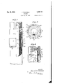
- Figure 1 is a view partly in section showing the 0 coupling positioned (.1 the hose and prior to being contracted, the contracting die being shown in place.
- Figure 2 is a view corresponding to Figure 1 with the die removed showing the coupling in its contracted or final condition.
- Figure 3 is a bottom view of the coupling removed from the hose.
- Figure 4 is a fragmentary sectional detail of the upper end of the insert.
- Figure 5 is an enlarged detail of a fragment of the hose.
- Figure 6 is a view showing a further form that the invention may take, such view being a fragmentary view and showing in partial section the 5 upper portion of the coupling.
- Figure 7 is a view of a further form of coupling with the portion of the hose adjacent thereto and about to be inserted into the coupling, such view being in partial section.
- Figure 8 is a view of the construction shown in Figure 7 after assembly.
- the hose coupling comprises an outer shell or body portion I whose outer end is threaded either internally, as shown, or externally, so that it may be attached to the appropriate device.
- This body portion is provided with a downwardly extending shell, the upper portion 2 of which, as viewed in Figures 1 and 2, is continuous while the lower portion 3 is interrupted at intervals by notches or slots 4 which may have straight sides adjacent their extreme ends and may con- 10 verge as the bottom of the notches are approached.
- This construction of notch as described and shown in Figure 1 is for the coupling before it has been contracted. When contracted,
- the body portion may be made of any suitable material. For example in the larger sizes malleable iron has been found satisfactory.
- An insert is secured within the body portion 20 and is adapted to enter the interior of the hose 5 during assembly, as shown in Figure 1.
- This insert has a tubular portion projecting downwardly, as viewed in Figure 1 and indicated by the reference character 6. It has a slightly 25 heavier upper portion 1 which is adapted to be pressed into the correspondingly bored portion of the body I of the coupling.
- This insert is also provided with an annular flange 8 which seats against a corresponding seat formed in the body 30 portion to limit the amount the insert can be pressed into the body portion.
- the upper outer corner of the portion 1 is bevelled, as indicated at 9, and when the insert is pressed into place,
- the insert is preferably formed of seamless steel tubing which is heat treated, 'carborized and hardened in accordance with the best practice at present known.
- This insert may be of other material but it is preferable to use the material specified so that if the rubber covering, as hereinafter described, after prolonged use is worn down to the metal, the life that this type of metal insert now has will be added to give the total life of the insert.
- a rubber covering i is formed on the insert prior to its assembly in the body portion.
- This rubber covering is vulcanized or otherwise formed on the insert and covers the entire inner surface thereof and extends around both ends of the insert and over the outer surface of the portion 6 thereof, as shown in Figure 1. The rubber covering firmly adheres to the insert.
- the portion 7 of the insert is forced into the body portion so as to secure a forced fit. Pressure is applied to the insert during this process at the flange 8 and no pressure is applied on the rubber covering.
- the space formed by the bevelled portion 9 at the upper end of the insert forms a small overflow space for the. rubber of the covering and prevents puckering or the formation of ridges on the inner side of this insert during the process of assembling the insert within the body of the coupling.
- weakening notches or grooves of generally triangular contour are formed interiorly of the portion 3 of the shell to facilitate the distortion or bending of the shell during contraction thereof, as will be hereinafter described.
- lugs l3 are provided and are preferably slightly bevelled.
- an overflow hole or relief hole 14 is provided at one or more points adjacent the extreme inner end of the hose.
- These relief openings may function in the same manner as that set forth in my above noted prior Patents No. 1,926,270 and No. 2,031,823 to provide relief for the air that may be imprisoned during the insertion of the hose into the coupling, as the hose has a relatively tight accurate fit therewith, and also to afford a relief for any excess rubber during the contraction, and additionally to afford relief for any liquid that may leak into the space above the inner end of the hose, to thus prevent the building up of pressure at this point. Any one or all of these func tions may be performed by these relief holes.
- the shell of the coupling is formed with a series of internal spiral grooves M and i5 so that the hose may be, in effect, screwed into place prior to contraction of the coupling.
- the lower cylindrical portion l6 forms a skirt like member and this skirt like effect may be emphasized as much as desired to provide a gradually lessening pressure on the hose adjacent the lower extreme end of the coupling, as viewed in Figure 2, to thereby minimize the chance of damaging the outer coating of the hose.
- the contracting is accomplished by providing a split die l9 which has a tapered outer face and fits within a correspondingly tapered die holder 20.
- This die is provided with a bevelled upper 7 portion 2
- the cylindrical portion 22 of the die is bored out and receives the clamping ring or retaining ring It, as shown in Figure 1, so that as the coupling is forced through the die, it passes through the clamping ring or retaining ring and thereafter when the die is opened, this continuous clamping ring holds the segments of the shell against expanding even if the tendency to expand might overcome the natural resistance of the contracted segments.
- the hose is formed of rubber and is provided with an offset or abrupt shoulder 23 which abuts the lower end of the composite insert.
- the inner surface 24 of the hose accurately aligns with the inner surface of the insert.
- the hose is heavily reinforced by a plurality of layers of duck wrapping indicated at 25 and 26 with interspersed spirally wound wires indicated generally at 21.
- the wires are preferably.
- the insert is indi: cated by the reference character 28 and has the rubber covering 29 thereon, as previously described, and the portion 30 thereof may have either a tight forced fit with the corresponding bored portion of the body M or may have a less tight fit.
- This portion 30 may be materially shorter than theportion 1 of Figure 1 if desired and reliance for the retention of the insert within the body portion may be placed at least partly upon the ring nut or locking ring 32 which is screwed into the body portion and which bears against the annular flange 33 formed integrally on the insert.
- This ring nut is provided with a plurality of notches 34 to receive the lugs on a cylindrical wrench so that the ring may be screwed in place without any damage whatsoever to the rubber covering of the insert.
- the fiange 33 may have a bevelled inner face, as shown, engaging the bevelled inner face of the bored out portion in the body of the coupling and, as previously described, the end of the rubber covering'is clamped between the upper end of the portion 30 of the insert and the inwardly projecting annular flange 35 of the body portion.
- the coupling may be as in Figure 1.
- the relief openings are indicated at 36.
- the body portion 31 is provided with an inwardly extending flange 38 and the segments, indicated generally at 39, are provided with interlocking portions 40 which may be hooked back oLthe ring 38 and thus locked to the body portion 31.
- each segment is also preferable to form each segment with a projecting lug 44 so that it acts somewhat as a spacer and yet allows a little freedom both for shifting and for. rocking during the positioning of the segments in' interlocking engagement with the body portion 31.
- a hardened ring 45 of relatively brittle material such, for example, as hard cast iron, is put into place to hold the ends of the segments expanded or, in other words, to hold them in interlocking engagement with the body portion prior'to the,
- the insert may be held to the body portion in the manner disclosed in connection with Figure 1 or Figure 6. It comprises the portion 41 corresponding to the portion 6 of Figure 1, and the enlarged portion 48 corresponding to the portion 1 of Figure 1. It is provided with the rubber covering 49, as previously described, and the rubber covering is clamped at its upper end between the annular flange 50 ofthe body portion and the end of the portion 48 of the insert.
- the lower end of the insert is preferably tapered, as shown, so that when it is assembled in the hose and the coupling is contracted, there are no abrupt changes in diameter between the insert and the hose but a gradual. tapering or gradual merging of the inner bore of theinsert and the inner bore of the hose is secured.
- the segments are contracted onto the hose 5
- the purpose of making the ring 45 relatively brittle is to allow the ring to be broken when the coupling is to be removed from a hose, as described in my prior Patent No. 2,086,- 703. As described in detail-in this patent, it is frequently the case that it is desired to save the body portion.
- the segments first tend to rock about their upper ends and grip the hose and are thereafter distorted and contracted.
- the construction is such that the interior of the segments before contraction forms a substantially cylindrical portion provided with spiral threads, such cylindrical portion being indicated by the reference character 53 in Figure 7.
- outer side tapers, as indicated at 54, and finally a relatively thinner skirt portion, having arelatively cylindrical inner bore 55 and a substantially cylindrical outer face 56,
- the hose in the form of the invention shown in Figures 7 and 8 is made with an end 58 which is externally reduced.
- the internal bore of the hose is uniform throughout.
- the hose is initially made with the externally reduced portion, as shown in Figure 7, or the internally reduced portion, as shown in Figure 5, and is furnished in this form, thus avoiding the necessity of cutting the hose or otherwise marring it.
- the outer surface of the rubber covered insert is preferably coated with rubber cement and if desired the corresponding inner surface of the hose may be similarly coated.
- This rubber cement acts as a lubricant during the forcing of the insert into the hose.
- coupling is such that a substantially continuous rubber lined passage is afforded through the coupling and into the hose, and that the ends of the rubber covering are held against loosening so that the rubber covering cannot be stripped loose by the flowing water.
- the invention provides a coupling in which the rubber covered insert may be assembled in the coupling without danger of damaging its rubber covering during assembly.
- a coupling for a hose comprising a body portion adapted to receive a hose and to be secured thereto, an insert carried by said body portion and securely attached thereto and adapted to enter the hose, and a rubber covering on the interior of said insert extending around the inner end thereof and clamped between such end and the body portion, said insert having an external flange and said body portion having a part against which said flange seats to prevent cutting of the clamped portion of said covering, said coupling having a relief space surrounding the clamped portion of said covering of the insert for receiving the overflow from said clamped portion of the covering of the insert.
- a body portion a hose extending into said body portion and held to said body portion, an insert carried by said body portion, and a rubber covering on the inner side of said insert, said rubber covering extending around the inner end of said insert and clamped between the inner end of the insert and the body portion and extending around the outer end of the insert and forming an external portion for said insert, said insert being provided with radially' projecting means for receiving a tool for assembling the insert within the body portion, said hose clamping the external portion of said covering between itself and the insert, whereby both ends of said covering are held against stripping from said insert.
- a coupling for a hose comprising a body portion adapted to receive a hose and to be secured thereto, said coupling having means for attachment to a fitting adjacent one end thereof, an insert carried by said body portion and rigidly attached thereto and having a tubular portion projecting outwardly, and a rubber covering on at least the interior of said tubular portion, said covering having one edge thereof clamped between the body portion and one end of the insert, whereby the clamped end of the rubber covering is protected from contact with the fitting.
- a coupling for a hose comprising a body porion adapted to receive a hose and to be secured thereto, an insert carried by said body portion and rigidly attached thereto and adapted to enter the hose, and a rubber covering on the interior of said insert extending around at least one end thereof and clamped betweensuch end and the-body portion, said insert having an external projection adapted to engage the body portion and said body portion having a part against which said projection seats to limit the clamping pressure on the clamped portion of the covering.
Description
Dec, 19, 1939. J. P. EASTMAN COUPLING Filed Aug. 27, 1937 3 Sheets-Sheet l w R 9 w W 7 4 W m f 1 i M W M fl V m W m Dec. 1939- J. P. EASTMAN 2,184,116
COUPLING Filed Aug. 27, 1937 5 Sheets-Sheet 2 Z24 if Q 7ATT ORNEY.
Dec. 19, 1939. J. P. EASTMAN COUPLING Filed Aug. 27, 1937 3 Sheets-Sheet 5 WdRNEY 1 Patented Dec; 19, 1939.
UNITED "STATES PATENT OFFICE 4 Claims.
This invention relates to couplings of the general type in which an outer shell and an inner insert are provided, the hose being received between such members and the shell being con- 5 tracted onto the hose to firmly grip it between the shell and the insert, and the invention, though directed to the coupling generally, is particularly directed to a novel form of insert.
In couplings for hoses which are used in the m handling of gritty water, such as the commonly called mud water" used in drilling wells, it has been found that the abrasive material carried by the flowing stream of water rapidly destroys the insert. Many attempts have been made to 18 remedy this defect and various types of inserts have been used in which as hard material as is commercially available has been employed but it has been found that the life of the coupling is relatively short due to the relatively short life 20 of the insert, as these inserts are worn away with considerable rapidity.
This invention is designed to provide a novel form of coupling which has an insert so made that it will greatly lessen the wear on the insert 2% when used in the manner hereinabove described,
and in which all of the heretofore available advantages as to the type or character of the metal forming the insert may be retained, and in addition a vastadvantage is added by the novel conw struction of the insert itself so that wear on the insert is greatly reduced.
In greater detail, objects of this invention are to provide a coupling in which the insert has a rubber covering so that the abrasive material will not cut into the insert but will be swept along by the stream of water without damage to the insert. It is believed that the cushioning action of the rubber greatly reduces the wear produced by the abrasive material.
00 Further objects are to provide a novel form of coupling in which a rubber covered insert is provided and is very securely attached to the body of the coupling in a manner to preclude damage to the rubber covering of the insert, though considerable pressures or forces may be exerted in assembling the device. I
Further objects are to provide a novel construction of coupling with its insert and with the hose attached so that a unitary construction is afforded with a rubber lining on the insert substantially continuous, with the inner rubber lining of the hose thereby not only protecting the metal against wear but also avoiding eddies and w whirls and thus greatly lessening the wear and the abrasive action due to the flowing stream of water with the suspended abrasives.
Further objects are to provide a construction of coupling which may be made in any size desired, for example relatively large sizes which are used on the reinforced heavy hoses for well drilling, and which is so made that cutting of the covering of the insert is prevented during the assembly of the parts constituting the device, the insert having its ends clamped or enclosed by adjacent portions of the coupling so that there is no chance of peeling the covering from the insert when the coupling is in use, means being provided to limit the amount of compression of the gripped ends of the covering to thereby preclude cutting and yet to secure the double advantage of firmly holding the edges of the covering and also at the same time providing a gasket between a portion of the insert and the shell of the coupling.
This invention is an improvement over that disclosed in my prior patents for Pressed-on hose coupling, No. 1,926,270 of September 12, 1933, and No. 2,031,823 of February 25, 1936, and my prior patent forPressed-on hose coupling and method of applying the same, No. 2,086,703 of July 13, 1937.
Embodiments of the invention are shown in the accompanying drawings, in which:
Figure 1 is a view partly in section showing the 0 coupling positioned (.1 the hose and prior to being contracted, the contracting die being shown in place.
Figure 2 is a view corresponding to Figure 1 with the die removed showing the coupling in its contracted or final condition.
Figure 3 is a bottom view of the coupling removed from the hose.
Figure 4 is a fragmentary sectional detail of the upper end of the insert.
Figure 5 is an enlarged detail of a fragment of the hose.
Figure 6 is a view showing a further form that the invention may take, such view being a fragmentary view and showing in partial section the 5 upper portion of the coupling.
Figure 7 is a view of a further form of coupling with the portion of the hose adjacent thereto and about to be inserted into the coupling, such view being in partial section.
Figure 8 is a view of the construction shown in Figure 7 after assembly.
Referring to the drawings, particularly Figures lto 4,.it will be seen that the hose coupling comprises an outer shell or body portion I whose outer end is threaded either internally, as shown, or externally, so that it may be attached to the appropriate device.
This body portion is provided with a downwardly extending shell, the upper portion 2 of which, as viewed in Figures 1 and 2, is continuous while the lower portion 3 is interrupted at intervals by notches or slots 4 which may have straight sides adjacent their extreme ends and may con- 10 verge as the bottom of the notches are approached. This construction of notch as described and shown in Figure 1 is for the coupling before it has been contracted. When contracted,
the walls of the notches are roughly parallel 15 throughout, as indicated in Figure 2.
The body portion may be made of any suitable material. For example in the larger sizes malleable iron has been found satisfactory.
An insert is secured within the body portion 20 and is adapted to enter the interior of the hose 5 during assembly, as shown in Figure 1. This insert has a tubular portion projecting downwardly, as viewed in Figure 1 and indicated by the reference character 6. It has a slightly 25 heavier upper portion 1 which is adapted to be pressed into the correspondingly bored portion of the body I of the coupling. This insert is also provided with an annular flange 8 which seats against a corresponding seat formed in the body 30 portion to limit the amount the insert can be pressed into the body portion. The upper outer corner of the portion 1 is bevelled, as indicated at 9, and when the insert is pressed into place,
an annular space is left, as shown in Figure 1, 85 at this point.
The insert is preferably formed of seamless steel tubing which is heat treated, 'carborized and hardened in accordance with the best practice at present known. This insert may be of other material but it is preferable to use the material specified so that if the rubber covering, as hereinafter described, after prolonged use is worn down to the metal, the life that this type of metal insert now has will be added to give the total life of the insert.
A rubber covering i is formed on the insert prior to its assembly in the body portion. This rubber covering is vulcanized or otherwise formed on the insert and covers the entire inner surface thereof and extends around both ends of the insert and over the outer surface of the portion 6 thereof, as shown in Figure 1. The rubber covering firmly adheres to the insert.
In assembling the insert and the body portion, the portion 7 of the insert is forced into the body portion so as to secure a forced fit. Pressure is applied to the insert during this process at the flange 8 and no pressure is applied on the rubber covering.
The insert is pressed into place until the flange 8 seats, as shown in Figure 1', at which time the extreme upper annular portion of the rubber covering ill will be clamped between the inwardly projecting annular portion H of the coupling and the end of the portion 1, but this part of the rubber covering cannot be cut as the inward motion of the insert is definitely determined and limited by the flange 8. However, this clamping of the rubber covering at its upper end serves the double purpose of providing a gasket between the upper end of the insert and the body portion of the coupling and also of providing a way of holding the extreme upper end of the covering clamped so that it cannot be peeled or stripped from the metal part of the insert.
The space formed by the bevelled portion 9 at the upper end of the insert forms a small overflow space for the. rubber of the covering and prevents puckering or the formation of ridges on the inner side of this insert during the process of assembling the insert within the body of the coupling.
As disclosed in my above noted Patent No. 10 2,086,703, weakening notches or grooves of generally triangular contour, as indicated by. the reference character I2, are formed interiorly of the portion 3 of the shell to facilitate the distortion or bending of the shell during contraction thereof, as will be hereinafter described.
Also it is to be noted that at spaced intervals around the bottom edge of the coupling, lugs l3 are provided and are preferably slightly bevelled. Also an overflow hole or relief hole 14 is provided at one or more points adjacent the extreme inner end of the hose. These relief openings may function in the same manner as that set forth in my above noted prior Patents No. 1,926,270 and No. 2,031,823 to provide relief for the air that may be imprisoned during the insertion of the hose into the coupling, as the hose has a relatively tight accurate fit therewith, and also to afford a relief for any excess rubber during the contraction, and additionally to afford relief for any liquid that may leak into the space above the inner end of the hose, to thus prevent the building up of pressure at this point. Any one or all of these func tions may be performed by these relief holes.
In order to secure an added grip upon the hose and also to facilitate insertion thereof, the shell of the coupling is formed with a series of internal spiral grooves M and i5 so that the hose may be, in effect, screwed into place prior to contraction of the coupling.
It is to be noted also that the coupling adjacent the lower cylindrical portion thereof, as indicated'by the reference character 16, has a larger bore than immediately thereabove and that thereafter a ring like neck is provided when the coupling is contracted, as shown in Figure 2, such ring like neck being indicated generally by the reference character I! in Figure 2.
The lower cylindrical portion l6 forms a skirt like member and this skirt like effect may be emphasized as much as desired to provide a gradually lessening pressure on the hose adjacent the lower extreme end of the coupling, as viewed in Figure 2, to thereby minimize the chance of damaging the outer coating of the hose.
When the coupling is contracted, as shown in Figure 2, it will be seen that a continuous band 18 surrounds the skirt portion 3 of the coupling and prevents spreading after it has been removed from the die. This ring is prevented from slipping off by the lugs [3.
The manner of contracting the coupling and positioning the ring may be as shown and described in my Patents No. 2,031,823 and No. 2,086,703. I
The contracting is accomplished by providing a split die l9 which has a tapered outer face and fits within a correspondingly tapered die holder 20. This die is provided with a bevelled upper 7 portion 2| for guiding and contracting the shell of the coupling and with a cylindrical lower portion 22 into which the coupling is forced.
The cylindrical portion 22 of the die is bored out and receives the clamping ring or retaining ring It, as shown in Figure 1, so that as the coupling is forced through the die, it passes through the clamping ring or retaining ring and thereafter when the die is opened, this continuous clamping ring holds the segments of the shell against expanding even if the tendency to expand might overcome the natural resistance of the contracted segments.
It ls to be noted from an inspection of Figures 1 and 2 that the inner surface of the composite insert and the inner bore of the hose are in alignment and thus a continuous rubber wall is presented to the flowing stream of abrasive-laden water. Whirls, eddies and disturbances are thus prevented.
One way of accomplishing this is to construct the hose so as to approximately fit the insert. For instance, as shown in Figure 5, the hose is formed of rubber and is provided with an offset or abrupt shoulder 23 which abuts the lower end of the composite insert. The inner surface 24 of the hose accurately aligns with the inner surface of the insert.
The hose is heavily reinforced by a plurality of layers of duck wrapping indicated at 25 and 26 with interspersed spirally wound wires indicated generally at 21. The wires are preferably.
diagonally wound with one layer crossing the next layer at an angle to secure the maximum reinforcement as indicated in the lower portion of Figure 1. It is to be distinctly understood, however, that the rubber of the hose permeates all these layers and bonds or binds all of them into a unitary reinforced structure. It is apparent that the end of the hose constructed as shown in Figure 1 with an offset has a direct cooperative relation with the coupling and its insert to prevent the formation of eddies and to give a continuous rubber inner surface without breaks in continuity or abrupt changes in diameter between the insert and the hose.
The invention may take other forms. For instance as shown in Figure 6, the insert is indi: cated by the reference character 28 and has the rubber covering 29 thereon, as previously described, and the portion 30 thereof may have either a tight forced fit with the corresponding bored portion of the body M or may have a less tight fit.
This portion 30 may be materially shorter than theportion 1 of Figure 1 if desired and reliance for the retention of the insert within the body portion may be placed at least partly upon the ring nut or locking ring 32 which is screwed into the body portion and which bears against the annular flange 33 formed integrally on the insert. This ring nut is provided with a plurality of notches 34 to receive the lugs on a cylindrical wrench so that the ring may be screwed in place without any damage whatsoever to the rubber covering of the insert.
If desired, the fiange 33 may have a bevelled inner face, as shown, engaging the bevelled inner face of the bored out portion in the body of the coupling and, as previously described, the end of the rubber covering'is clamped between the upper end of the portion 30 of the insert and the inwardly projecting annular flange 35 of the body portion. Otherwise the coupling may be as in Figure 1. The relief openings are indicated at 36.
In the form of the invention shown in Figures 7 and'8 the body portion 31 is provided with an inwardly extending flange 38 and the segments, indicated generally at 39, are provided with interlocking portions 40 which may be hooked back oLthe ring 38 and thus locked to the body portion 31.
- Preferably there is a slight space between successive segments,the upper or cylindrical portion of the segments having parallel walls, as indicated at 4|, even prior to.contracting and having slanting walls 42 before contracting and parallel walls '43. After contraction all of these walls approximately align and thus parallel faces are presented from one segment to the other.
It is also preferable to form each segment with a projecting lug 44 so that it acts somewhat as a spacer and yet allows a little freedom both for shifting and for. rocking during the positioning of the segments in' interlocking engagement with the body portion 31. After the segments are interlocked with the body portion, a hardened ring 45 of relatively brittle material, such, for example, as hard cast iron, is put into place to hold the ends of the segments expanded or, in other words, to hold them in interlocking engagement with the body portion prior'to the,
assembling of the coupling on the hose.
The insert may be held to the body portion in the manner disclosed in connection with Figure 1 or Figure 6. It comprises the portion 41 corresponding to the portion 6 of Figure 1, and the enlarged portion 48 corresponding to the portion 1 of Figure 1. It is provided with the rubber covering 49, as previously described, and the rubber covering is clamped at its upper end between the annular flange 50 ofthe body portion and the end of the portion 48 of the insert.
The lower end of the insert is preferably tapered, as shown, so that when it is assembled in the hose and the coupling is contracted, there are no abrupt changes in diameter between the insert and the hose but a gradual. tapering or gradual merging of the inner bore of theinsert and the inner bore of the hose is secured.
The segments are contracted onto the hose 5| by forcing the coupling through a die, as previously described, and as shown in my above noted Patent No. 2,086,703, a retaining ring 52 being provided in exactly the same manner as described in connection with Figure 1 and as shown in my Patent No. 2,086,703. The purpose of making the ring 45 relatively brittle is to allow the ring to be broken when the coupling is to be removed from a hose, as described in my prior Patent No. 2,086,- 703. As described in detail-in this patent, it is frequently the case that it is desired to save the body portion. Under these conditions the external clamping ring is first cut in two and thereafter a sharp hammer blow is delivered to one of the segments, thus breaking the brittle ring 45 and allowing the segments to be detached from the body portion so that the body portion of the coupling may be used again as this part represents the greatest cost.
During contracting of the coupling, the segments first tend to rock about their upper ends and grip the hose and are thereafter distorted and contracted. As previously described in connection with Figure 1, the construction is such that the interior of the segments before contraction forms a substantially cylindrical portion provided with spiral threads, such cylindrical portion being indicated by the reference character 53 in Figure 7.
The outer side, however, tapers, as indicated at 54, and finally a relatively thinner skirt portion, having arelatively cylindrical inner bore 55 and a substantially cylindrical outer face 56,
is provided. This results in the formation of a ring like neck, as indicated by the reference character 51, Figure 8, corresponding to the ring neck i1, Figure 2.
The provision ofthis ring neck effect secures a greater contraction at a point spaced inwardly from the outer end of the hose, as clearly shown in Figures 2 and 8, and in each of my above noted patents.
In the form of the invention shown in Figures 7 and 8 the hose, as may be seen from Figure 7, is made with an end 58 which is externally reduced. The internal bore of the hose, however, is uniform throughout.
Preferably the hose is initially made with the externally reduced portion, as shown in Figure 7, or the internally reduced portion, as shown in Figure 5, and is furnished in this form, thus avoiding the necessity of cutting the hose or otherwise marring it.
It is to be understood that the features of the several forms of the invention are interchangeable and the several forms are not intended to indicate that other types of couplings may not be used with the rubber covered insert, but are intended to show a variety of couplings with which the rubber covered insert may be used.
In all forms of the inventtion prior to the insertion of the hose, the outer surface of the rubber covered insert is preferably coated with rubber cement and if desired the corresponding inner surface of the hose may be similarly coated. This rubber cement acts as a lubricant during the forcing of the insert into the hose. Further, by having the internal ridges in the coupling formed in the manner of a spiral, it is clear that the hose may be inserted into the coupling and the parts may have relative rotation to facilitate the insertion of the hose.
It will be seen that a novel form of coupling has been provided in which the insert is covered with a rubber covering and it is to be distinctly understood that the invention in its broadest aspects covers any suitable yielding material of the general nature of rubber.
It will be seen further that the construction of coupling is such that a substantially continuous rubber lined passage is afforded through the coupling and into the hose, and that the ends of the rubber covering are held against loosening so that the rubber covering cannot be stripped loose by the flowing water.
Further it is to be noted that substantially the same internal bore exists both in the insert and in the hose in all forms of the invention and in certain forms identically the same bore exists, thus minimizing the chance of the formation of eddies.
It will be seen further that the invention provides a coupling in which the rubber covered insert may be assembled in the coupling without danger of damaging its rubber covering during assembly.
Although the invention has been described as particularly applicable for the handling of abrasive-laden water, obviously it is intended that any fluid carrying abrasives may be handled by this device.
Although this invention has been described in considerable detail, it is to be understood that such description is intended as illustrative rather than limiting, as the invention may be variously embodied and is to be interpreted as claimed.
I claim:
1. A coupling for a hose comprising a body portion adapted to receive a hose and to be secured thereto, an insert carried by said body portion and securely attached thereto and adapted to enter the hose, and a rubber covering on the interior of said insert extending around the inner end thereof and clamped between such end and the body portion, said insert having an external flange and said body portion having a part against which said flange seats to prevent cutting of the clamped portion of said covering, said coupling having a relief space surrounding the clamped portion of said covering of the insert for receiving the overflow from said clamped portion of the covering of the insert.
2. In a coupling construction, a body portion, a hose extending into said body portion and held to said body portion, an insert carried by said body portion, and a rubber covering on the inner side of said insert, said rubber covering extending around the inner end of said insert and clamped between the inner end of the insert and the body portion and extending around the outer end of the insert and forming an external portion for said insert, said insert being provided with radially' projecting means for receiving a tool for assembling the insert within the body portion, said hose clamping the external portion of said covering between itself and the insert, whereby both ends of said covering are held against stripping from said insert.
3. A coupling for a hose comprising a body portion adapted to receive a hose and to be secured thereto, said coupling having means for attachment to a fitting adjacent one end thereof, an insert carried by said body portion and rigidly attached thereto and having a tubular portion projecting outwardly, and a rubber covering on at least the interior of said tubular portion, said covering having one edge thereof clamped between the body portion and one end of the insert, whereby the clamped end of the rubber covering is protected from contact with the fitting.
4. A coupling for a hose comprising a body porion adapted to receive a hose and to be secured thereto, an insert carried by said body portion and rigidly attached thereto and adapted to enter the hose, and a rubber covering on the interior of said insert extending around at least one end thereof and clamped betweensuch end and the-body portion, said insert having an external projection adapted to engage the body portion and said body portion having a part against which said projection seats to limit the clamping pressure on the clamped portion of the covering.
JOSEPH PETER EASTMAN.
Priority Applications (1)
| Application Number | Priority Date | Filing Date | Title |
|---|---|---|---|
| US161182A US2184116A (en) | 1937-08-27 | 1937-08-27 | Coupling |
Applications Claiming Priority (1)
| Application Number | Priority Date | Filing Date | Title |
|---|---|---|---|
| US161182A US2184116A (en) | 1937-08-27 | 1937-08-27 | Coupling |
Publications (1)
| Publication Number | Publication Date |
|---|---|
| US2184116A true US2184116A (en) | 1939-12-19 |
Family
ID=22580172
Family Applications (1)
| Application Number | Title | Priority Date | Filing Date |
|---|---|---|---|
| US161182A Expired - Lifetime US2184116A (en) | 1937-08-27 | 1937-08-27 | Coupling |
Country Status (1)
| Country | Link |
|---|---|
| US (1) | US2184116A (en) |
Cited By (8)
| Publication number | Priority date | Publication date | Assignee | Title |
|---|---|---|---|---|
| US2800145A (en) * | 1953-05-12 | 1957-07-23 | Resistoflex Corp | Barrier hose and hose assembly |
| US3131642A (en) * | 1962-11-30 | 1964-05-05 | Wilfley & Sons Inc A | Standpipe connection for centrifugal pumps |
| US3237974A (en) * | 1965-02-10 | 1966-03-01 | Resistoflex Corp | Hose fitting |
| US3454291A (en) * | 1967-02-15 | 1969-07-08 | Electrical Fittings Corp | Raintight electrical connector |
| US20020063424A1 (en) * | 2000-11-08 | 2002-05-30 | Alfagomma S.P.A. | Pipe fitting for inside coated pipes and method for its installation |
| US20060163871A1 (en) * | 2005-01-21 | 2006-07-27 | Saint-Gobain Performance Plastics Corporation | Flared thru assembly |
| EP1975495A1 (en) * | 2007-03-29 | 2008-10-01 | Tokai Rubber Industries, Ltd. | Hose with joint fitting for conveying carbon dioxide refrigerant |
| US20100207387A1 (en) * | 2009-02-18 | 2010-08-19 | Parker-Hannifin Corporation | Hose fitting |
-
1937
- 1937-08-27 US US161182A patent/US2184116A/en not_active Expired - Lifetime
Cited By (12)
| Publication number | Priority date | Publication date | Assignee | Title |
|---|---|---|---|---|
| US2800145A (en) * | 1953-05-12 | 1957-07-23 | Resistoflex Corp | Barrier hose and hose assembly |
| US3131642A (en) * | 1962-11-30 | 1964-05-05 | Wilfley & Sons Inc A | Standpipe connection for centrifugal pumps |
| US3237974A (en) * | 1965-02-10 | 1966-03-01 | Resistoflex Corp | Hose fitting |
| US3454291A (en) * | 1967-02-15 | 1969-07-08 | Electrical Fittings Corp | Raintight electrical connector |
| US20020063424A1 (en) * | 2000-11-08 | 2002-05-30 | Alfagomma S.P.A. | Pipe fitting for inside coated pipes and method for its installation |
| US6905146B2 (en) * | 2000-11-08 | 2005-06-14 | Aflagomma S.P.A. | Pipe fitting for inside coated pipes and method for its installation |
| US20060163871A1 (en) * | 2005-01-21 | 2006-07-27 | Saint-Gobain Performance Plastics Corporation | Flared thru assembly |
| US7500696B2 (en) * | 2005-01-21 | 2009-03-10 | Saint-Gobain Performance Plastics Corporation | Flared thru assembly |
| EP1975495A1 (en) * | 2007-03-29 | 2008-10-01 | Tokai Rubber Industries, Ltd. | Hose with joint fitting for conveying carbon dioxide refrigerant |
| US20080236694A1 (en) * | 2007-03-29 | 2008-10-02 | Tokai Rubber Industries, Ltd. | Hose with Joint Fitting for Conveying Carbon Dioxide Refrigerant |
| US20100207387A1 (en) * | 2009-02-18 | 2010-08-19 | Parker-Hannifin Corporation | Hose fitting |
| US8888140B2 (en) * | 2009-02-18 | 2014-11-18 | Parker-Hannifin Corporation | Hose fitting |
Similar Documents
| Publication | Publication Date | Title |
|---|---|---|
| US3995655A (en) | Apparatus for and method of making a service line connection through a fitting | |
| US2201372A (en) | Pipe coupling | |
| US3140106A (en) | Lip seal case fitting | |
| US4117643A (en) | Anchor bolt thread protector and sleeve system | |
| US5689862A (en) | Safety clamp | |
| US5044393A (en) | Shell cutter | |
| US2184116A (en) | Coupling | |
| US10520125B2 (en) | Universal thread protector | |
| US2456203A (en) | Coupling for tubular members | |
| US1798944A (en) | Tool for removing broken stud bolts and the like | |
| US4690435A (en) | Hose coupling | |
| US5299644A (en) | Well starter head | |
| US5205356A (en) | Well starter head | |
| US2983477A (en) | Plug valve saddle | |
| US3620245A (en) | Perforator and apparatus for using same | |
| US5038818A (en) | Insertion assembly for a pipe completion plug | |
| US2127284A (en) | Pipe coupling | |
| US4576403A (en) | Pressure fitting | |
| US1897561A (en) | Tube puller | |
| US5737822A (en) | Corporation stop assembly | |
| US3287033A (en) | Hose coupling | |
| US5054512A (en) | Insertion assembly for a pipe stopper | |
| US2308147A (en) | Protector for drill pipes | |
| US2281632A (en) | Jacket for drill pipe couplings | |
| US2252920A (en) | Hose coupling |