US2486056A - Combined package and applicator - Google Patents
Combined package and applicator Download PDFInfo
- Publication number
- US2486056A US2486056A US668454A US66845446A US2486056A US 2486056 A US2486056 A US 2486056A US 668454 A US668454 A US 668454A US 66845446 A US66845446 A US 66845446A US 2486056 A US2486056 A US 2486056A
- Authority
- US
- United States
- Prior art keywords
- outer tube
- tube
- cap
- applicator
- inner tube
- Prior art date
- Legal status (The legal status is an assumption and is not a legal conclusion. Google has not performed a legal analysis and makes no representation as to the accuracy of the status listed.)
- Expired - Lifetime
Links
Images
Classifications
-
- A—HUMAN NECESSITIES
- A61—MEDICAL OR VETERINARY SCIENCE; HYGIENE
- A61M—DEVICES FOR INTRODUCING MEDIA INTO, OR ONTO, THE BODY; DEVICES FOR TRANSDUCING BODY MEDIA OR FOR TAKING MEDIA FROM THE BODY; DEVICES FOR PRODUCING OR ENDING SLEEP OR STUPOR
- A61M31/00—Devices for introducing or retaining media, e.g. remedies, in cavities of the body
Definitions
- COMBINED PACKAGE AND APPLI CATOR Filed May 9, 1946 Patented Oct. 25, 1949 COMBINED PACKAGE AND APPLICATOR Charles A. Oclassen, Kenmore, N. Y., assignor to Foster-Millburn Company, Buffalo, N. Y.
- This invention relates to applicators of the type usable for introducing powders, pastes, jellies or the like into orifices oi the body, for feminine hygiene or for medicinal purposes.
- Applicators have heretofore been provided which comprise a tube formed to be inserted into a body cavity and from which a charge of medicinal or other material may be expelled to a cavity by means of a plunger or inner tube, and these devices were intended for repeated use.
- devices of this type it is difficult to discharge the desired quantity of material to the body cavity and these devices have the further objections that it is frequently difiicult to recharge the same with the desired amount of material for a single application, and it is also difficult to thoroughly clean and sterilize the devices after each use of the same.
- One of the objects of this invention is to provide an applicator of this type of inexpensive construction, which may contain sufficient material for one application or treatment and which also serves as a package or container for the preparation to be administered, and which can be discarded after use. Another object is to provide a combined applicator and container of this type of improved and simplified construction and which is positive and reliable in use both as an applicator and as a package. Other objects and advantages of this invention will appear from the following description and claim.
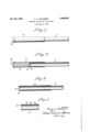
- Fig. 1 is a longitudinal elevation of a combined applicator and package embodying this invention.
- Fig. 2 is a central sectional view thereof.
- Fig. 3 is a central sectional view thereof, showing the parts thereof in the positions which they occupy at the completion of the application of the contents to a body cavity.
- Fig. 4 is a fragmentary section, on an enlarged scale, of the outer tube of the combined applicator and package.
- Devices serving both as applicators and packages according to this invention each include an outer tube 6 and an inner tube 1 telescopically arranged in the outer tube.
- the inner tube is somewhat longer than the outer tube, so that when the inner tube is completely inserted into the outer tube, a portion of the inner tube will extend beyond an end of the outer tube.
- the inner tube forms a plunger or piston to expel material from the outer tube, and any suitable means may be provided to close that end of the inner tube which is arranged within the outer tube.
- a cap 8 is secured to that end of the inner tube.
- This cap preferably has an integral cylindrical flange 9 which extends around the peripheral portion of the inner end of the inner tube, and the outer surface of the flange 9 has a slidable and substantially liquid-tight fit within the outer tube.
- the cap consequently, forms a piston reciprocable within the outer tube.
- the device When the parts are in the positions shown in Figs. 1 and 2, the device forms a package or container for a charge 10 of the material or substance to be administered, and this substance is securely sealed in the space provided therefor, so that the device forms a package or container in which the substance or material may be kept in clean and sanitary condition until used.
- the entire device preferably is further wrapped in a suitable envelope or enclosure of paper, cellophane, or other suitable material (not shown).
- the closure cap I2 When the device is to be used, the closure cap I2 is first removed. The device may then be inserted into a cavity while the parts are in the positions shown in Figs. 1 and 2 with the end uncovered by the closure cap leading, and when the outer tube has been inserted to the desired or necessary extent, the inner tube 1 is pushed into the outer tube in a direction to expel the material l0. When the expulsion of the material has been completed, the parts will occupy the relative positions shown in Fig. 3, and the entire device may then be removed from the cavity.
- the inner tube I is preferably first inserted into the outer tube to a slight extent sufficient to expel a small quantity of the contents, so that they project beyond the outer tube, whereupon the device may be inserted into the cavity and used as described. Before withdrawing the device, the inner tube 1 is preferably otherwise secured to the inner layer 15.
- the entire device is preferably made of inexpensive materials, so that the device may be discarded after one use. Any suitable materials may be employed for this purpose.
- the outer tube is made as indicated in Fig. 4, in which [5 represents an inner layer of a material which is inert with reference to the material I contained in the tube.
- a waxed paper is suitable for most purposes for which the device is used, but cellophane or other sheet materials may be substituted for the waxed paper.
- the material of which the inner layer i is made is selected not only for its ability to contain the material It] without deterioration of the material or of the inner layer IE, but also to provide a surface on which the cap.
- a layer It of a relatively stifi material such, for example, as cardboard which may be wrapped spirally around a mandrel or tool on which the outer tube is formed, and the layer It is suitably cemented or
- the cardboard or re-inforcing layer l6 may be covered on the outer surface thereof with a cover sheet I1 which may be of ordinary paper, clay coated paper, or other suitable material, and this layer is also glued, cemented or otherwise secured to the re-iniorcing or cardboard layer l6.
- the interior of the re-inforcing layer may be suitably protected by a coating of any suitable material.
- the outer tubes 6 may be formed in long lengths and cut to size.
- this end of the outer tube which is closed by the cap I2 is preferably dipped in wax or other suitable material to impregnate the ends of the intermediate and outer layer l6 and I! against contact with the material contained in the outer tube. i9, Fig. 4, represents such coating applied to the end of the outer tube.
- the two caps 8 and I2 may be formed of paper or other material, and if desired, these caps may be treated with wax or other coating material to protect them from the material It].
- the inner tube 1 may be constructed in the same manner as the outer tube 6, but since the interior of this tube does not contact the material I! to be administered, the inner wax paper layer may be omitted.
- the device described has the advantage that the correctquantity of material to be administered may be accurately inserted into each device, so that it is not necessary for the user to place the material in to the device.
- the device forms a package in which the material may be sealed so that it willbe kept in a clean, sanitary and usable condition. Since the combined package and applicator is made of inexpensive material, it may be discarded after use, so that no cleansing or sterilizing of the same after use is necessary.
- Devices of this kind can be individually wrapped in envelopes or covering materials, or may be placed in boxes or containers which will keep the outer tube in sterile condition, so that devices of this type are ready for instant use. They occupy a relatively small space and can be easily carried by a person for use when necessary.
- a combined applicator and package for administering substances to a body cavity including inner and outer tubes telescopically arranged with the inner tube of greater length than the outer tube, said outer tube being made of cardboard and having an inner layer of waxed paper and having the discharge end of said tube coated with wax, to protect said tube against the substance to be administered, said inner tube extending partly into said outer tube and forming between one end of said outer tube and an end of the inner tube, a space for the substance to be administered, a cap for closing the inner end of said inner tube rigidly secured to said inner tube and having a substantial liquid tight and slidable fit within said outer tube, and a closure cap formed to be removably secured to said end of said outer tube for closing said end of said outer tube, said caps being made of a material which is inert with reference to said substance, said two caps forming the ends of a space in said outer tube for containing said substance to be administered and forming with said outer tube a package for said substance, said inner tube and the cap thereon, when said closure cap is
Description
Oct. 25, 1949. c. AuOCLASSEN 2,486,056
COMBINED PACKAGE AND APPLI CATOR Filed May 9, 1946 Patented Oct. 25, 1949 COMBINED PACKAGE AND APPLICATOR Charles A. Oclassen, Kenmore, N. Y., assignor to Foster-Millburn Company, Buffalo, N. Y.
Application May 9, 1946, Serial No. 668,454
1 Claim.
This invention relates to applicators of the type usable for introducing powders, pastes, jellies or the like into orifices oi the body, for feminine hygiene or for medicinal purposes.
Applicators have heretofore been provided which comprise a tube formed to be inserted into a body cavity and from which a charge of medicinal or other material may be expelled to a cavity by means of a plunger or inner tube, and these devices were intended for repeated use. With devices of this type, it is difficult to discharge the desired quantity of material to the body cavity and these devices have the further objections that it is frequently difiicult to recharge the same with the desired amount of material for a single application, and it is also difficult to thoroughly clean and sterilize the devices after each use of the same.
One of the objects of this invention is to provide an applicator of this type of inexpensive construction, which may contain sufficient material for one application or treatment and which also serves as a package or container for the preparation to be administered, and which can be discarded after use. Another object is to provide a combined applicator and container of this type of improved and simplified construction and which is positive and reliable in use both as an applicator and as a package. Other objects and advantages of this invention will appear from the following description and claim.
In the accompanying drawings which illustrate by way of example one embodiment of this invention:
Fig. 1 is a longitudinal elevation of a combined applicator and package embodying this invention.
Fig. 2 is a central sectional view thereof.
Fig. 3 is a central sectional view thereof, showing the parts thereof in the positions which they occupy at the completion of the application of the contents to a body cavity.
Fig. 4 is a fragmentary section, on an enlarged scale, of the outer tube of the combined applicator and package.
Devices serving both as applicators and packages according to this invention each include an outer tube 6 and an inner tube 1 telescopically arranged in the outer tube. The inner tube is somewhat longer than the outer tube, so that when the inner tube is completely inserted into the outer tube, a portion of the inner tube will extend beyond an end of the outer tube. The inner tube forms a plunger or piston to expel material from the outer tube, and any suitable means may be provided to close that end of the inner tube which is arranged within the outer tube. In the construction, for this purpose, a cap 8 is secured to that end of the inner tube. This cap preferably has an integral cylindrical flange 9 which extends around the peripheral portion of the inner end of the inner tube, and the outer surface of the flange 9 has a slidable and substantially liquid-tight fit within the outer tube. The cap consequently, forms a piston reciprocable within the outer tube. When the inner tube is partly withdrawn from the outer tube as shown in Figs. 1 and 2, a space is formed within the outer tube between the cap 8 at the left in Figs. 1 and 2 within which any suitable substance or material H] to be administered may be contained, and the cap 8 securely closes one end of this space. The other end of this space may be closed by means of a suitable closure cap l2 secured to the end of the outer tube 6. This closure cap is removable from the outer tube, but the cap 8 is glued, cemented or otherwise securely fastened to the inner tube.
When the parts are in the positions shown in Figs. 1 and 2, the device forms a package or container for a charge 10 of the material or substance to be administered, and this substance is securely sealed in the space provided therefor, so that the device forms a package or container in which the substance or material may be kept in clean and sanitary condition until used. The entire device preferably is further wrapped in a suitable envelope or enclosure of paper, cellophane, or other suitable material (not shown).
When the device is to be used, the closure cap I2 is first removed. The device may then be inserted into a cavity while the parts are in the positions shown in Figs. 1 and 2 with the end uncovered by the closure cap leading, and when the outer tube has been inserted to the desired or necessary extent, the inner tube 1 is pushed into the outer tube in a direction to expel the material l0. When the expulsion of the material has been completed, the parts will occupy the relative positions shown in Fig. 3, and the entire device may then be removed from the cavity. If the material It, within the device, is in the nature of a jelly or salve, then after removal of the closure cap 12, the inner tube I is preferably first inserted into the outer tube to a slight extent sufficient to expel a small quantity of the contents, so that they project beyond the outer tube, whereupon the device may be inserted into the cavity and used as described. Before withdrawing the device, the inner tube 1 is preferably otherwise secured to the inner layer 15.
turned to detach the jelly or salve from the cap 8 thereof before withdrawing the device.
The entire device is preferably made of inexpensive materials, so that the device may be discarded after one use. Any suitable materials may be employed for this purpose. Preferablyv the outer tube is made as indicated in Fig. 4, in which [5 represents an inner layer of a material which is inert with reference to the material I contained in the tube. A waxed paper is suitable for most purposes for which the device is used, but cellophane or other sheet materials may be substituted for the waxed paper. The material of which the inner layer i is made is selected not only for its ability to contain the material It] without deterioration of the material or of the inner layer IE, but also to provide a surface on which the cap.
8 will readily slide.
Around the inner layer [5 is wrapped a layer It of a relatively stifi material such, for example, as cardboard which may be wrapped spirally around a mandrel or tool on which the outer tube is formed, and the layer It is suitably cemented or The cardboard or re-inforcing layer l6 may be covered on the outer surface thereof with a cover sheet I1 which may be of ordinary paper, clay coated paper, or other suitable material, and this layer is also glued, cemented or otherwise secured to the re-iniorcing or cardboard layer l6. In place of the inner sheet material it, the interior of the re-inforcing layer may be suitably protected by a coating of any suitable material.
The outer tubes 6 may be formed in long lengths and cut to size. In order to protect the ends di the intermediate and outer layers I6 and I? from contact with the material Hi, this end of the outer tube which is closed by the cap I2 is preferably dipped in wax or other suitable material to impregnate the ends of the intermediate and outer layer l6 and I! against contact with the material contained in the outer tube. i9, Fig. 4, represents such coating applied to the end of the outer tube.
The two caps 8 and I2 may be formed of paper or other material, and if desired, these caps may be treated with wax or other coating material to protect them from the material It]. The inner tube 1 may be constructed in the same manner as the outer tube 6, but since the interior of this tube does not contact the material I!) to be administered, the inner wax paper layer may be omitted.
The device described has the advantage that the correctquantity of material to be administered may be accurately inserted into each device, so that it is not necessary for the user to place the material in to the device. The device forms a package in which the material may be sealed so that it willbe kept in a clean, sanitary and usable condition. Since the combined package and applicator is made of inexpensive material, it may be discarded after use, so that no cleansing or sterilizing of the same after use is necessary. By arranging the flange of the cap 8 about the exterior of the inner tube, a tight fit of the cap within the outer tube can readily be provided, and in the use of the applicator the force necessary to expel the material I0 is less than would be required if the entire outer wall of the inner tube I were in frictional contact with the. inner surface of the outer tube.
Devices of this kind can be individually wrapped in envelopes or covering materials, or may be placed in boxes or containers which will keep the outer tube in sterile condition, so that devices of this type are ready for instant use. They occupy a relatively small space and can be easily carried by a person for use when necessary.
I claim:
A combined applicator and package for administering substances to a body cavity, including inner and outer tubes telescopically arranged with the inner tube of greater length than the outer tube, said outer tube being made of cardboard and having an inner layer of waxed paper and having the discharge end of said tube coated with wax, to protect said tube against the substance to be administered, said inner tube extending partly into said outer tube and forming between one end of said outer tube and an end of the inner tube, a space for the substance to be administered, a cap for closing the inner end of said inner tube rigidly secured to said inner tube and having a substantial liquid tight and slidable fit within said outer tube, and a closure cap formed to be removably secured to said end of said outer tube for closing said end of said outer tube, said caps being made of a material which is inert with reference to said substance, said two caps forming the ends of a space in said outer tube for containing said substance to be administered and forming with said outer tube a package for said substance, said inner tube and the cap thereon, when said closure cap is removed, being movable toward said end of said outer tube to act as a piston to expel the substance to be administered from the outer tube.
CHARLES A. OCLASSEN.
REFERENCES CITED The following references are of record in the file of this patent:
UNITED STATES PATENTS Number Name Date 401,157 Glasscock Apr. 9, 1889 2,185,536 Borland Jan. 2, 1940 2,413,480 Winter Dec. 31, 1946
Priority Applications (1)
| Application Number | Priority Date | Filing Date | Title |
|---|---|---|---|
| US668454A US2486056A (en) | 1946-05-09 | 1946-05-09 | Combined package and applicator |
Applications Claiming Priority (1)
| Application Number | Priority Date | Filing Date | Title |
|---|---|---|---|
| US668454A US2486056A (en) | 1946-05-09 | 1946-05-09 | Combined package and applicator |
Publications (1)
| Publication Number | Publication Date |
|---|---|
| US2486056A true US2486056A (en) | 1949-10-25 |
Family
ID=24682371
Family Applications (1)
| Application Number | Title | Priority Date | Filing Date |
|---|---|---|---|
| US668454A Expired - Lifetime US2486056A (en) | 1946-05-09 | 1946-05-09 | Combined package and applicator |
Country Status (1)
| Country | Link |
|---|---|
| US (1) | US2486056A (en) |
Cited By (14)
| Publication number | Priority date | Publication date | Assignee | Title |
|---|---|---|---|---|
| US2616424A (en) * | 1950-05-12 | 1952-11-04 | John W Brown | Medication unit |
| US2691980A (en) * | 1952-02-18 | 1954-10-19 | Jones John Leslie | Expendable vaginal applicator |
| US2712315A (en) * | 1954-03-26 | 1955-07-05 | Klr Lab Inc | Disposable applicator |
| US2848265A (en) * | 1956-04-23 | 1958-08-19 | France Ivan E La | Flare holder |
| US3850173A (en) * | 1973-04-30 | 1974-11-26 | American Home Prod | Flushable vaginal applicator |
| US4865590A (en) * | 1987-09-09 | 1989-09-12 | Marmar Joel L | Disposable prostatic aspiration device |
| US5015231A (en) * | 1989-04-21 | 1991-05-14 | Scimed Life Systems, Inc. | Multipart split sleeve balloon protector for dilatation catheter |
| US5053007A (en) * | 1989-12-14 | 1991-10-01 | Scimed Life Systems, Inc. | Compression balloon protector for a balloon dilatation catheter and method of use thereof |
| US5137512A (en) * | 1989-03-17 | 1992-08-11 | Scimed Life Systems, Inc. | Multisegment balloon protector for dilatation catheter |
| US5282789A (en) * | 1992-09-15 | 1994-02-01 | Niemand Industries, Inc. | Disposable medicine applicator |
| US5286193A (en) * | 1991-10-30 | 1994-02-15 | Roane James B | Endodontic gutta percha placement |
| US6013055A (en) * | 1997-11-13 | 2000-01-11 | Boston Scientific Corporation | Catheter balloon having selected folding characteristics |
| US6110192A (en) * | 1996-09-23 | 2000-08-29 | Boston Scientific Corporation | Catheter balloon having raised radial segments |
| US7993358B2 (en) | 2005-02-11 | 2011-08-09 | Boston Scientific Scimed, Inc. | Cutting balloon catheter having increased flexibility regions |
Citations (3)
| Publication number | Priority date | Publication date | Assignee | Title |
|---|---|---|---|---|
| US401157A (en) * | 1889-04-09 | Syringe | ||
| US2185536A (en) * | 1938-03-18 | 1940-01-02 | Borland Alexander | Syringe |
| US2413480A (en) * | 1944-04-07 | 1946-12-31 | Sanitary Tampon Corp | Tampon applicator |
-
1946
- 1946-05-09 US US668454A patent/US2486056A/en not_active Expired - Lifetime
Patent Citations (3)
| Publication number | Priority date | Publication date | Assignee | Title |
|---|---|---|---|---|
| US401157A (en) * | 1889-04-09 | Syringe | ||
| US2185536A (en) * | 1938-03-18 | 1940-01-02 | Borland Alexander | Syringe |
| US2413480A (en) * | 1944-04-07 | 1946-12-31 | Sanitary Tampon Corp | Tampon applicator |
Cited By (15)
| Publication number | Priority date | Publication date | Assignee | Title |
|---|---|---|---|---|
| US2616424A (en) * | 1950-05-12 | 1952-11-04 | John W Brown | Medication unit |
| US2691980A (en) * | 1952-02-18 | 1954-10-19 | Jones John Leslie | Expendable vaginal applicator |
| US2712315A (en) * | 1954-03-26 | 1955-07-05 | Klr Lab Inc | Disposable applicator |
| US2848265A (en) * | 1956-04-23 | 1958-08-19 | France Ivan E La | Flare holder |
| US3850173A (en) * | 1973-04-30 | 1974-11-26 | American Home Prod | Flushable vaginal applicator |
| US4865590A (en) * | 1987-09-09 | 1989-09-12 | Marmar Joel L | Disposable prostatic aspiration device |
| US5137512A (en) * | 1989-03-17 | 1992-08-11 | Scimed Life Systems, Inc. | Multisegment balloon protector for dilatation catheter |
| US5015231A (en) * | 1989-04-21 | 1991-05-14 | Scimed Life Systems, Inc. | Multipart split sleeve balloon protector for dilatation catheter |
| US5053007A (en) * | 1989-12-14 | 1991-10-01 | Scimed Life Systems, Inc. | Compression balloon protector for a balloon dilatation catheter and method of use thereof |
| US5286193A (en) * | 1991-10-30 | 1994-02-15 | Roane James B | Endodontic gutta percha placement |
| US5382161A (en) * | 1991-10-30 | 1995-01-17 | Roane; James B. | Endodontic gutta percha placement |
| US5282789A (en) * | 1992-09-15 | 1994-02-01 | Niemand Industries, Inc. | Disposable medicine applicator |
| US6110192A (en) * | 1996-09-23 | 2000-08-29 | Boston Scientific Corporation | Catheter balloon having raised radial segments |
| US6013055A (en) * | 1997-11-13 | 2000-01-11 | Boston Scientific Corporation | Catheter balloon having selected folding characteristics |
| US7993358B2 (en) | 2005-02-11 | 2011-08-09 | Boston Scientific Scimed, Inc. | Cutting balloon catheter having increased flexibility regions |
Similar Documents
| Publication | Publication Date | Title |
|---|---|---|
| US2486056A (en) | Combined package and applicator | |
| US6957958B2 (en) | Unit dose applicator with material chamber | |
| US3757782A (en) | Fluid pressurizable swab applicator for medicament, antiseptic or the like | |
| US2743038A (en) | Paste dispenser | |
| US2178840A (en) | Medicament introducer | |
| US2509241A (en) | Applicator | |
| WO2005060905A1 (en) | Swab and producing method thereof | |
| WO2002094367A1 (en) | Dry handle swab assembly | |
| US2690181A (en) | Enema applicator | |
| US5282789A (en) | Disposable medicine applicator | |
| US2691982A (en) | Disposable applicator | |
| JP2007524423A (en) | Application tool with sealed liquid | |
| US1782526A (en) | Tubular container | |
| US2516846A (en) | Applicator | |
| US2925100A (en) | Dispensing container | |
| DE1943290B2 (en) | DISPENSER CONTAINER FOR LIQUID OR VISCOSE DRUG | |
| US2847011A (en) | Single dose applicator | |
| US2066868A (en) | Dispensing unit | |
| US7476046B2 (en) | Applicator and material dispensing system | |
| US2712315A (en) | Disposable applicator | |
| US4721204A (en) | Package for holding and using ampules | |
| US1139368A (en) | Ampul. | |
| US2590138A (en) | Dispenser | |
| US2864368A (en) | Foil envelope and enclosing tube disposable applicator | |
| US2856927A (en) | Disposable applicator pull cord type |