US2489751A - Roof or covering - Google Patents
Roof or covering Download PDFInfo
- Publication number
- US2489751A US2489751A US607167A US60716745A US2489751A US 2489751 A US2489751 A US 2489751A US 607167 A US607167 A US 607167A US 60716745 A US60716745 A US 60716745A US 2489751 A US2489751 A US 2489751A
- Authority
- US
- United States
- Prior art keywords
- chambers
- liquid
- roof
- liquids
- chamber
- Prior art date
- Legal status (The legal status is an assumption and is not a legal conclusion. Google has not performed a legal analysis and makes no representation as to the accuracy of the status listed.)
- Expired - Lifetime
Links
Images
Classifications
-
- B—PERFORMING OPERATIONS; TRANSPORTING
- B60—VEHICLES IN GENERAL
- B60H—ARRANGEMENTS OF HEATING, COOLING, VENTILATING OR OTHER AIR-TREATING DEVICES SPECIALLY ADAPTED FOR PASSENGER OR GOODS SPACES OF VEHICLES
- B60H1/00—Heating, cooling or ventilating [HVAC] devices
Definitions
- the invention relates to, new and useful im ⁇ provements in ⁇ root ⁇ construction.
- Another object. ot the invention is to provideA a root' construction that will absorb and ⁇ radiate heat. energy from the ⁇ sun. in. cold Weather and re. fleet heat energy during Warm weather.
- Still another object4 of' the invention is to4 pro vide a ⁇ roof construction that: can be made selec tively transparent, translucent or opaque.
- Yet another' objectz of the: invention is to ⁇ provide a roof construction. that, will selectively ab.- sorb, or transmit certain desired portions. of the light spectrum and block- ⁇ or reect other harm--4 ful or undesired portions;
- a further object' of the invention is to provide. a roof construction of the. aborefmentioned character that can ⁇ beA readily adapted to any desired structure such, as a. building or automotive vehicle.
- a still further object of the. invention is to pro. vide a roof ⁇ ofthe above-mentioned character that is simple ⁇ in construction and. inexpensive to manufacture..
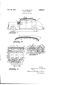
- FIG. 1 is a side elevation; of; an automotive vehi- ⁇ le having a ⁇ roof construction embodying the ⁇ etant invention, parts thereof being broken away and shown in section for clearness of illustration,
- Fig. 2 is airagmentary vertical sectional view taken onthe line. 2.-2 of Eig. 1
- Fig. 3 is a diagrammaticveurshowing the manner in which fluids: are circulated through shallow chambers in the roof material to control its light and heat transmitting- ⁇ properties.
- Fig. 4 is an: enlarged fragmentary, vertical sec.- tional View taken on. the line- 4- oi Fig. 1.
- the present invention may be employed as a roof or side Wall of any permanent or tinted,J portable1 or movable structure whether it be a building such as a residence of the like, or a vehicle such as an automobile. bus, airplane. or the, like. and. for any roof or wall thereof, the light. transmitting light absorbing, or light reflecting qualities of,- ⁇ l/'1.1icln,5 it may be desired to vary.
- a roof construction embodying the presen-t invention isshowl-n andl described in connection with an automotive vehicle.
- vehicle tops have usually beeny made of metal or a suitable- Waterw prooi fabric and; either event, are opaque and dark in color sothat they block all light rays and readily absorb and radiate heat energy.
- the interior of the Vehicle is relatively darkA at all timesand, in the summertime or during periods of Warm weather, becomes uncomfortably warm.
- the roof or top ⁇ is formed' of transparent material and provided with one or moresha1-lowl chambers which preferably extend across the entire roofV area.
- Any transparent material may be used, but certain plastics such ⁇ as synthetic resins are preferred, since they are relatively strong and nonshatterable, and can be easily formed in any desired shape.
- the heat and light transfer'V propertires of the roof' are controlled by lling the chamber or chambers with suitable colored or opaque liquids. If more than one chamber is provided, they are arranged one above the other so. ⁇ that, if desired, the chambers canV be lled with dierent liquids and the: combined properties. of' the liquids used to control the transparency characteristics. of the roof.
- both the light transmitting and heat absorbing power of the root can be. selectively controlled.
- the particu. lar liquid. or combination oi liquids that will pro. prise a certain desired result can be easily detere minedhy those skilled the art from. the known physical properties of; various. liquids.. In general, light: colored liquids, Whether transparent or opaque, reflect heat energy rather than absorb it, ⁇
- color-.ed liquids goed absorbers of heat energy regardless of their transparency characteristics.
- mercuryY produces anopaque roof with high. reflecting powerv and lower heat absorption, ind-ia ink; or asimilar rliid produces. an opaque roof with low reflecting power and high heat ⁇ absorption.
- Nonopaqueblue liqufids transmit most of the light Spetlfum butte-1' undesirable actinic raul-S. ⁇ T may be employed; in the; root ⁇ chambers; at various times, liquids: should be used that do not: wet the roof material, or alternatively, the chamber Walls may be treated with a suitable, solid, liquid; or gaseous agen-t such asl-beeswax, petroleum was.
- High molecular weight organic compounds such as dithenyl-mono-ortho-xenyl-phosphate, triethyl-phosphate, tributyl-phosphate, dioctylsebacate, and diethyl-heXyl-phthalate have been found to be most satisfactory. Liquids of this type are nonwetting to most materials and they can be obtained in any color by the use of suitable dyes which are soluble in them.
- a transparent or translucent wall structure formed to provide a single film or layer of liquid may be employed or one which is formed to provide two or more such lms or layers.
- the roof structure shown in the drawings is illustrated as being formed to provide two such i'llms or layers of liquid, as by such provision a more comprehensive disclosure of the present invention may be made.
- an automotive vehicle having a hood I0, a dashboard I2, and a top I4.
- the latter is constructed in accordance with the present invention and comprises vertically disposed, longitudinally and transversely curved pieces of transparent sheet material, i6, I8, and 28 which are maintained in uniformly spaced relation by a plurality of spacers 22.
- the lower and intermediate sheets I6 and I8 flare outwardly against the inner surface of sheet 20 and are sealed thereto in any suitable manner to provide fluid-tight chambers 24 and 26.
- These chambers are shallow, being preferably from a 32nd to a 16th of an inch in depth, and extend across the full length and width of the vehicle top.
- valve casing When liquid is charged to the upper chamber 26, air in the chamber is vented to the atmosphere through an opening 28 located at the highest point in the curved upper sheet 20. This opening is controlled by a float valve 30.
- the valve casing has a cylindrical lower portion 32 provided with a radial base flange 34 which is riveted or otherwise secured to the material 20 and a tapered upper portion 36 provided at its apex with an air Vent 38.
- the latter is controlled by a conical valve 4D mounted on the upper end of a valve stem 42 which is supported in a spider bearing 44.
- a float of cork or the like At the lower end of stem 42 and disposed in chamber 26 is a float of cork or the like which follows the surface of the liquid in the chamber and moves the valve relative to the air vent 38.
- oat 46 pushes valve 40 upwardly but does not close vent 38 until the chamber is lled with liquid.
- float 46 holds the valve rmly against the top of the casing to close the air vent 38 and prevents escape of liquid therethrough.
- the valve closes a certain amount of air is trapped in the casing above the liquid and this air cushions surging of the liquid in the roof chamber and forms a pressure relief means for expansion and contraction of the liquid.
- Air is vented from the lower chamber 24 through a float valve 48 which is identical in construction and operation to the float valve 36 except that the lower portion 32 of the valve casing is formed with a downward extension 58 which projects through chamber 26 and is threaded in a collar 52.
- the latter is mounted in an opening 54 in the intermediate roof sheet i8 and includes a radial flange 56 which engages the sheet around opening 54 and is attached thereto by screws 58 or the like.
- Valve stem 42 is, of course, considerably longer in this adaption of the valve to position float 46 in the lower chamber 24.
- valve 48 communicates only with the lower chamber 24 and prevents intermingling of fluids in the two chambers.
- suitable liquids are introduced into chambers 24 and 26 to control the heat and light transfer of properties of the vehicle top.
- Fig. 3 one form of apparatus for supplying either or both of the chambers with the same or different liquids and for draining the liquids therefrom.
- the apparatus includes three liquid containers 60, 62, and 64 which may conveniently be mounted under the hood I0 behind dashboard l2. It is to be understood that, while three containers are here shown, the invention is not limited to the use of any particular number of containers. In general, the number of containers used will depend entirely upon the manner in which the heat and light properties of the roof are to be varied.
- container 66 is filled with a liquid such as mercury that will render the roof opaque and is a reflector of heat energy
- container 62 is lled with a liquid such as India ink that will render the roof opaque and is an absorber of heat energy
- container 64 is filled with a suitable blue liquid that will transmit all of the light spectrum but the actinic rays.
- the various liquids in containers 60, 62 and 64 are charged to roof chambers 24 and 26 by a manually actuated pump 66 and liquids in the roof chambers are returned to their respective containers by a manually actuated pump 68.
- the pumps are conventional and identical in construction and operation. Each includes a cylindrical casing 'E6 provided with an inlet 12 in its forward end and an outlet 'I4 in its side wall adjacent the forward end.
- a piston 16, mounted for reciprocation in the casing 16 is provided with an operating handle i8 which projects through the rearward end of the casing.
- Both pumps are preferably mounted with the cylinder 'l0 disposed behind dashboard l2 and the operating handle 18 'extending through the dashboard.
- tainers 00, 02 and 64 that the bottoms of conare provided with separate outlet pipes 80, 82 and 84 controlled by manually actuated valves 86, 88 and 90, respectively.
- Each of the outlet pipes discharges into a manifold 92 which is connected to the inlet 'l2 of pump 66 by a pipe d.
- a check valve 96 in the latter pipe is adapted automatically to open when piston l5 moves back in casing '
- 00 leads from the outlet 'le of pump 50 to the lower roof chamber 24 and this pipe is provided adjacent its end with a branch pipe it nowadays controlled by manually operated valve
- 06 in pipe 08 automatically opens when the piston 16 advances, and closes when the piston is retracted. Only one liquid at a time is pumped to the roof chambers to prevent contamination or intermingling of the respective liquids.
- valves 8E, 08 and 90 are maintained normally closed and when it is desired to ill one or both of the roof chambers with liquid from one of the containers, the valve in the discharge pipe of that container only is opened se that retraction of piston 16 sucks the selected liquid into cylinder '10.
- 06 closes to prevent liquid in the roof chambers from also being drawn into the pump cylinder.
- valve 9S closes to prevent back ow of liquid into the container, and valve
- 00 is open
- the liquid will flow into the lower chamber 2li
- 04 is open
- the liquid will flow into the upper chamber 26
- both of these valves are open, both the upper and lower chambers will receive the liquid.
- either or both of the. roof chambers can be lled with any of the available liquids by repeated operations of pump 56. After the roof chambers are filled, the manually operated valve in the discharge pipe of the container and valves
- 08 controlled by the manually-operated valve H0 leads from the lower chamber 24 to the inlet 'l2 of pump 60. Adjacent its outer or upper end, pipe
- Branch ⁇ pipe Ilz is controlled Aby a manually-operated valve H4. Adjacent its inner or lower end, pipe
- pipe H6 is controlled by a manual1y-operated valve i8.
- the outlet 14 of pump 6B is connected to containers 60, 62 and 64 by a pipe
- the inlet pipes are controlled by manually-,operated valves
- 20 is controlled by a check valve
- 36 of the type equipped with a check valve which, when the manual control is open, is automatically opened by retraction of piston l@ to admit air to the casing and automatically closed by -advancement'of the piston.
- both of the roof chambers are. filled with the same liquid and it is desired to empty them it is merely necessary to open valves
- the pump is actuated with pet cock
- Fig. 1 and diagrammatically illustrated in Fig.
- Pump 68 can then be manipulated to return liquid in the pipes to container 62 thus clearingthe system.
- An opaque roof that is a poor absorber of heat energy can then be obtained without removing the liquid in chamber 24 by merely pumping mercury from container 00 into the upper chamber 26.
- the pigment or other constituents in India ink sometimes tend to settle out and deposit on the walls of the chambers and piping.
- the same effect can be obtained by providing containers of red and green liquids which may conveniently be any of those hereinabove mentioned suitably colored by soluble dyes.
- red and green liquids which may conveniently be any of those hereinabove mentioned suitably colored by soluble dyes.
- a roof construction comprising spaced upper and lower members of transparent sheet material sealed at their edges to provide a closed chamber therebetween, means for lling said chamber with a liquid, automatic means communicating with the atmosphere and operable by liquid in the chamber to trap a body of air in the chamber above said liquid, whereby said air cushions surging of the liquid in said chamber, and means for draining the liquid from the chamber.
- a roof construction comprising a hollow, transparent member; liquid in the internal chamber of said member capable of altering the light or heat transfer properties of the member; and valve means in one wall of the chamber operable by said liquid to trap a body of air in the chamber, whereby said air cushions surging of said liquid in the chamber.
- a roof construction comprising a hollow, transparent member; means for introducing a plurality of different fluids into the internal chamber of the member; means forming a film on the walls of said chamber, said film renderf ing said walls substantially nonabsorbent and nonadsorbent to fluids introduced into said chamber; and means for drawing the fluids from said chamber.
- a roof construction comprising a relatively thin member capable of transmitting both heat and light energy and provided with a shallow internal chamber; a liquid capable of altering the light or heat transfer properties of said member; and means for circulating said liquid through the chamber.
- a roof construction comprising a relatively thin, substantially transparent member provided with separate chambers, said chambers being essentially shallow and disposed one above the other; and means for introducing different liquids into each of said chambers.
- a roof construction comprising a substantially transparent sheet material provided with a plurality of vertically spaced shallow chambers; means for circulating different liquids separately through said chambers; and means forming films on the walls of said chambers for preventing the liquids from wetting said walls.
- a roof construction comprising a substantially transparent sheet material provided with separate upper and lower chambers, said chambers being shallow and substantially co-extensive, and means for introducing different liquids into each of said upper and lower chambers, each of said liquids having a predetermined effect on the heat or light transfer properties of the material and collectively having a different effect upon said properties.
- a roof construction comprising a substanitally transparent sheet material provided with separate upper and lower chambers, a liquid capable of altering the heat or light transfer properties of the sheet material, means for introducing said liquid into one of said chambers at a point below the top of the same, means for draining the liquid from said chamber, a second liquid capable of altering the eiect of the first liquid on the heat or light transfer properties of the material, means for introducing the second liquid into the other chamber at a point below the top of the same, means for draining the second liquid from said other chamber, and a float valve at the top of each chamber, said valves venting their respective chambers to the atmosphere and operable by liquids therein to trap air above said liquids, whereby the trapped air in said chambers cushions surging of the liquid in the chambers.
- transparent sheet material provided with superposed, relatively shallow chambers; a plurality of different liquids capable of altering the light or heat-transfer properties of said material; separate containers for said liquids; means for selectively introducing each of said liquids into the chambers and for drawing the liquids from the chambers back to their respective containers, said means including conduits between said containers and said chambers, means for forcing liquid under pressure from said containers to said chambers, and valve means in said conduits for controlling the flow of liquid therethrough, whereby any of said liquids can be selectively introduced into either of said chambers independently of the other liquids; and means forming films on the walls of said chambers and said conduits to prevent said liquids from wetting the same.
- transparent sheet material provided with superposed relatively shallow chambers; a plurality of different liquids adapted to be introduced into said chambers and each having a different effect on the light or heat transfer properties of said material; separate containers for each of said liquids; means for separately introducing each of said liquids into said chambers and for draining each of said liquids from the chambers back to its respective container, said means including a pump for forcing liquid to the chambers; a separate pump for forcing liquid from the chambers, conduit means establishing communication between said containers and the fluid inlets of said pumps, conduit means establishing communication between the discharge ports of said pumps and the chambers at a point below the tops of the latter, and valve means in said conduits for controlling the flow of liquid therethrough, whereby any of said liquids can be selectively introduced into said chambers independently of the other liquids; and a float valve in the wall and at the top of each chamber, each of said valves normally open to vent its respective chamber to the atmosphere but adapted to be closed by liquid in said chamber to trap
- transparent sheet material provided with superposed relatively shallow chambers; a plurality of different liquids adapted to be introduced into said chambers and each having a diiferent effect on the light or heat transfer properties of said material; separate containers for each of said 9 liquids; means for separately introducing each of said liquids into said chambers and for draining each of said liquids from the chambers back to its respective container, said means including a pump for forcing liquid to the chambers; a separate pump for forcing liquid from the chambers, conduit means establishing communication between said containers and the uid inlets of said pumps, conduit means establishing communication between the discharge ports of said pumps and the chambers at a point below the tops of the latter, and Valve means in said conduits for controlling the flow of liquid therethrough, whereby any of said liquids can be selectively introduced into said chambers independently of the other liquids; means forming films on the walls of said chambers and said conduits for preventing said liquids from wetting the same; and a float valve in the wall
Description
Nov. 29, 1949 G, v. CANDLER, JR
ROOF OR COVERING Filed July 26, 1945 INVENTOR. @ea/ye K .HvJ/rg;
BY m'@ v/g' Patented Nov. 29 1949 [TED STATES RQGF R COVERING George V..Can.dlcr, .1r., Grosse PointeFarms, Mich.. Application July 26; 1945, SerialNo. 607316.?.
11 Claims. 1
The invention relates to, new and useful im`` provements in` root` construction.
It is an important object of the. present invenf tion to. provide aroof'oi transparent material andto vary or modify its transparency characteris tics` selectively from cleartransparency to. absoA lute opaque to thereby control; both the heat. and light transfer properties of the material.
Another object. ot the invention is to provideA a root' construction that will absorb and` radiate heat. energy from the` sun. in. cold Weather and re. fleet heat energy during Warm weather.
Still another object4 of' the invention is to4 pro vide a` roof construction that: can be made selec tively transparent, translucent or opaque.
Yet another' objectz of the: invention is to` provide a roof construction. that, will selectively ab.- sorb, or transmit certain desired portions. of the light spectrum and block-` or reect other harm--4 ful or undesired portions;
A further object' of the invention is to provide. a roof construction of the. aborefmentioned character that can` beA readily adapted to any desired structure such, as a. building or automotive vehicle.
A still further object of the. invention is to pro. vide a roof` ofthe above-mentioned character that is simple` in construction and. inexpensive to manufacture..
In the drawing., forming: apart ci thisA specincation,y and` Whereinlike numerals are employed to designate like parts, throughout the same,
1 is a side elevation; of; an automotive vehi- \\le having a` roof construction embodying the` etant invention, parts thereof being broken away and shown in section for clearness of illustration,
Fig. 2 is airagmentary vertical sectional view taken onthe line. 2.-2 of Eig. 1
Fig. 3 is a diagrammaticveurshowing the manner in which fluids: are circulated through shallow chambers in the roof material to control its light and heat transmitting-` properties., and
Fig. 4, is an: enlarged fragmentary, vertical sec.- tional View taken on. the line- 4- oi Fig. 1.
it will be understood that the present invention may be employed as a roof or side Wall of any permanent or tinted,J portable1 or movable structure whether it be a building such as a residence of the like, or a vehicle such as an automobile. bus, airplane. or the, like. and. for any roof or wall thereof, the light. transmitting light absorbing, or light reflecting qualities of,-\l/'1.1icln,5 it may be desired to vary.
'For the purpose of illustration, a roof construction embodying the presen-t invention isshowl-n andl described in connection with an automotive vehicle. Heretofore, vehicle tops have usually beeny made of metal or a suitable- Waterw prooi fabric and; either event, are opaque and dark in color sothat they block all light rays and readily absorb and radiate heat energy. As a result, the interior of the Vehicle is relatively darkA at all timesand, in the summertime or during periods of Warm weather, becomes uncomfortably warm.
According to the instant invention, the roof or top` is formed' of transparent material and provided with one or moresha1-lowl chambers which preferably extend across the entire roofV area. Any transparent material may be used, but certain plastics such` as synthetic resins are preferred, since they are relatively strong and nonshatterable, and can be easily formed in any desired shape. The heat and light transfer'V propertires of the roof' are controlled by lling the chamber or chambers with suitable colored or opaque liquids. If more than one chamber is provided, they are arranged one above the other so.` that, if desired, the chambers canV be lled with dierent liquids and the: combined properties. of' the liquids used to control the transparency characteristics. of the roof.
By properly selecting the liquids, both the light transmitting and heat absorbing power of the root can be. selectively controlled. The particu. lar liquid. or combination oi liquids that will pro. duce a certain desired result can be easily detere minedhy those skilled the art from. the known physical properties of; various. liquids.. In general, light: colored liquids, Whether transparent or opaque, reflect heat energy rather than absorb it,`
and dark. color-.ed liquids goed absorbers of heat energy regardless of their transparency characteristics. For example, mercuryY produces anopaque roof with high. reflecting powerv and lower heat absorption, ind-ia ink; or asimilar rliid produces. an opaque roof with low reflecting power and high heat` absorption. Nonopaqueblue liqufids transmit most of the light Spetlfum butte-1' undesirable actinic raul-S.` T may be employed; in the; root` chambers; at various times, liquids: should be used that do not: wet the roof material, or alternatively, the chamber Walls may be treated with a suitable, solid, liquid; or gaseous agen-t such asl-beeswax, petroleum was. clear lacquer, o1: methyl-ohlorofsilane, that will mais@ it nonab.-` sorbent or nonadsorbent to.4 the liquids; Ii solid 5s agents are used, the surfaces of the transparent sheets which form the walls of the chambers must be treated before the roof is fabricated; however, the liquid or gaseous agents can be circulated through the system at any time to render the surfaces nonabsorbent and nonadsorbent. Obviously, the latter agents are preferred since they treat not only the roof chambers but also the pipes which serve the chambers. If nonwetting liquids or agents are not employed, some of the liquid adheres to the chamber walls and contaminates the next liquid used.
High molecular weight organic compounds, such as dithenyl-mono-ortho-xenyl-phosphate, triethyl-phosphate, tributyl-phosphate, dioctylsebacate, and diethyl-heXyl-phthalate have been found to be most satisfactory. Liquids of this type are nonwetting to most materials and they can be obtained in any color by the use of suitable dyes which are soluble in them.
In general, it is better to avoid liquids carrying a suspension of solid particles since the latter settle out and obstruct the roof chambers as well as the passages through which liquid is supplied to and drained from the chambers. Furthermore, the particles have a tendency to deposit on the chamber walls and thus alter the transparency characteristics of the roof material and contaminate liquids subsequently charged to the chambers.
It is to be understood that in the application of the present invention a transparent or translucent wall structure formed to provide a single film or layer of liquid may be employed or one which is formed to provide two or more such lms or layers. For the purpose of illustration the roof structure shown in the drawings is illustrated as being formed to provide two such i'llms or layers of liquid, as by such provision a more comprehensive disclosure of the present invention may be made.
For a more detailed description of the invention, reference is had' to the drawing wherein is shown an automotive vehicle having a hood I0, a dashboard I2, and a top I4. The latter is constructed in accordance with the present invention and comprises vertically disposed, longitudinally and transversely curved pieces of transparent sheet material, i6, I8, and 28 which are maintained in uniformly spaced relation by a plurality of spacers 22. At their peripheries, the lower and intermediate sheets I6 and I8 flare outwardly against the inner surface of sheet 20 and are sealed thereto in any suitable manner to provide fluid-tight chambers 24 and 26. These chambers are shallow, being preferably from a 32nd to a 16th of an inch in depth, and extend across the full length and width of the vehicle top.
When liquid is charged to the upper chamber 26, air in the chamber is vented to the atmosphere through an opening 28 located at the highest point in the curved upper sheet 20. This opening is controlled by a float valve 30. The valve casing has a cylindrical lower portion 32 provided with a radial base flange 34 which is riveted or otherwise secured to the material 20 and a tapered upper portion 36 provided at its apex with an air Vent 38. The latter is controlled by a conical valve 4D mounted on the upper end of a valve stem 42 which is supported in a spider bearing 44. At the lower end of stem 42 and disposed in chamber 26 is a float of cork or the like which follows the surface of the liquid in the chamber and moves the valve relative to the air vent 38. As the liquid rises in chamber 26,
oat 46 pushes valve 40 upwardly but does not close vent 38 until the chamber is lled with liquid. When this occurs, float 46 holds the valve rmly against the top of the casing to close the air vent 38 and prevents escape of liquid therethrough. When the valve closes, a certain amount of air is trapped in the casing above the liquid and this air cushions surging of the liquid in the roof chamber and forms a pressure relief means for expansion and contraction of the liquid.
Air is vented from the lower chamber 24 through a float valve 48 which is identical in construction and operation to the float valve 36 except that the lower portion 32 of the valve casing is formed with a downward extension 58 which projects through chamber 26 and is threaded in a collar 52. The latter is mounted in an opening 54 in the intermediate roof sheet i8 and includes a radial flange 56 which engages the sheet around opening 54 and is attached thereto by screws 58 or the like. Valve stem 42 is, of course, considerably longer in this adaption of the valve to position float 46 in the lower chamber 24. By reason of the extension 50 and collar 52, valve 48 communicates only with the lower chamber 24 and prevents intermingling of fluids in the two chambers.
As suggested, suitable liquids are introduced into chambers 24 and 26 to control the heat and light transfer of properties of the vehicle top. This may be done in any suitable manner; however, for the purpose of illustration, there is shown in Fig. 3 one form of apparatus for supplying either or both of the chambers with the same or different liquids and for draining the liquids therefrom. The apparatus includes three liquid containers 60, 62, and 64 which may conveniently be mounted under the hood I0 behind dashboard l2. It is to be understood that, while three containers are here shown, the invention is not limited to the use of any particular number of containers. In general, the number of containers used will depend entirely upon the manner in which the heat and light properties of the roof are to be varied. If it is desired to control only the transparency or heat transfer property of the roof, one container may be sucient, while if both the transparency and heat transfer properties of the roof are to be controlled, two or more containers may be necessary, depending upon the particular effects or result to be obtained. For the purpose of illustration, it may be assumed that container 66 is filled with a liquid such as mercury that will render the roof opaque and is a reflector of heat energy, that container 62 is lled with a liquid such as India ink that will render the roof opaque and is an absorber of heat energy, and that container 64 is filled with a suitable blue liquid that will transmit all of the light spectrum but the actinic rays.
The various liquids in containers 60, 62 and 64 are charged to roof chambers 24 and 26 by a manually actuated pump 66 and liquids in the roof chambers are returned to their respective containers by a manually actuated pump 68. The pumps are conventional and identical in construction and operation. Each includes a cylindrical casing 'E6 provided with an inlet 12 in its forward end and an outlet 'I4 in its side wall adjacent the forward end. A piston 16, mounted for reciprocation in the casing 16, is provided with an operating handle i8 which projects through the rearward end of the casing. Both pumps are preferably mounted with the cylinder 'l0 disposed behind dashboard l2 and the operating handle 18 'extending through the dashboard. When the con-l tainers and pumps are mounted on the vehicle in the above manner they are out of the way yet readily accessible for replacement or repair and the pumps can be easily operated by the driver or other person seated on the front seat of the vehicle.
It will be observed tainers 00, 02 and 64 that the bottoms of conare provided with separate outlet pipes 80, 82 and 84 controlled by manually actuated valves 86, 88 and 90, respectively. Each of the outlet pipes discharges into a manifold 92 which is connected to the inlet 'l2 of pump 66 by a pipe d. A check valve 96 in the latter pipe is adapted automatically to open when piston l5 moves back in casing '|0 and to close when piston i6 advances. A pipe 9B controlled by manually operated valve |00 leads from the outlet 'le of pump 50 to the lower roof chamber 24 and this pipe is provided adjacent its end with a branch pipe it?! controlled by manually operated valve |04 which communicates with the upper roof chamber 2e. A check valve |06 in pipe 08 automatically opens when the piston 16 advances, and closes when the piston is retracted. Only one liquid at a time is pumped to the roof chambers to prevent contamination or intermingling of the respective liquids. Thus, valves 8E, 08 and 90 are maintained normally closed and when it is desired to ill one or both of the roof chambers with liquid from one of the containers, the valve in the discharge pipe of that container only is opened se that retraction of piston 16 sucks the selected liquid into cylinder '10. When the piston moves back in the cylinder, check valve |06 closes to prevent liquid in the roof chambers from also being drawn into the pump cylinder. When the piston is pushed forwardly in cylinder l0, valve 9S closes to prevent back ow of liquid into the container, and valve |06 opens permitting the liquid to flow from the pump to the vehicle roof. It will be readily apparent that if only valve |00 is open, the liquid will flow into the lower chamber 2li; if only valve |04 is open, the liquid will flow into the upper chamber 26; and if both of these valves are open, both the upper and lower chambers will receive the liquid. Thus, either or both of the. roof chambers can be lled with any of the available liquids by repeated operations of pump 56. After the roof chambers are filled, the manually operated valve in the discharge pipe of the container and valves |00 and |04 are closed.
The system for returning the liquid from the roof chambers 24 and 26 i-s now described inV detail. A liquid return pipe |08 controlled by the manually-operated valve H0 leads from the lower chamber 24 to the inlet 'l2 of pump 60. Adjacent its outer or upper end, pipe |08 is provided vvith a branch pipe l2 through which liquid drains from the upper roof chamber 26. Branch` pipe Ilz is controlled Aby a manually-operated valve H4. Adjacent its inner or lower end, pipe |00 is connected by another branch pipe l I6 to pipe SS intermediate the manually-operated valves |00 and |04 and check valve |06. Branch.
pipe H6 is controlled by a manual1y-operated valve i8. The outlet 14 of pump 6B is connected to containers 60, 62 and 64 by a pipe |20 and a plurality of inlet pipes |22, |24 and l26.` The inlet pipes are controlled by manually-,operated valves |28, |30 and |32, and pipe |20 is controlled by a check valve |34 which automatically closes` when piston '16 is piston, advances.
retracted and opens when the Also attached tothe inlet end of' casing 't0 is va''manually-operated pet cock |36 of the type equipped with a check valve which, when the manual control is open, is automatically opened by retraction of piston l@ to admit air to the casing and automatically closed by -advancement'of the piston.
If both of the roof chambers are. filled with the same liquid and it is desired to empty them it is merely necessary to open valves |00, |04, ||0 and lili as well as the valve in the inlet pipe of the container to which the liquid is to be returned and to repeatedly actuate pump 68. At iirst the pump is actuated with pet cock |35 closed so'that the pump draws liquid from the roof chambers through pipes S8, |02, |108 and ||2 and discharges it to the container through pipe |20. As shown in Fig. 1, and diagrammatically illustrated in Fig. 3, pipe 98 and its branch |02 communicate with the forward ends of the roof chambers 2li and 26 While pipe |08 and its branch i l2 communicate with the rearward ends of these chamber-s. This arrangement is necessary in viewof the transverse and longitudinal curvature in the roof. Pump e8 also sucks liquid from pump et when valve H3 is open and pumps it back to the container when valve ils is closed. Thus, any of the liquid which remains in the manifold 02 or pipe 9e is returned to the container as well as liquid from the roof chambers 2t and 20. When all liquid has been drained from chambers 2li and 2d and from pump 06, the manual control of pet cock |36 is opened so that pump 68 pumps air under pressure into pipe |20 to force residual liquid therein into the container. The system is then cleared so that a dierent liquid can be charged to the roof chambers without danger of contamination. It will be readily appreciated that, ii the liquids in tanks E50, 52 and d4 are to be used separately, one roof chamber is sufcient. However, it may be expedient under some circumstances to ll the lower chamber 2d with India ink from container t2 in order to obtain an opaque roof that is a good absorber of heat energy. The liquid is charged to the chamber through pipe 98 and, when the chamber is lled, valve |00 is closed. Pump 68 can then be manipulated to return liquid in the pipes to container 62 thus clearingthe system. An opaque roof that is a poor absorber of heat energy can then be obtained without removing the liquid in chamber 24 by merely pumping mercury from container 00 into the upper chamber 26.
The pigment or other constituents in India ink sometimes tend to settle out and deposit on the walls of the chambers and piping. The same effect can be obtained by providing containers of red and green liquids which may conveniently be any of those hereinabove mentioned suitably colored by soluble dyes. When one of the roof chambers is lled with the green liquid and the other roof chamber with the red liquid, the combined effect of the two liquids is to block the. entire light spectrum and produce an opaque roof. This method of controlling the light transfer properties of the roof has the further advantage that diierent effects and varying degrees of transparency can be obtained by using the red and green liquids separately. l
While red and green liquids have been speciiically mentioned by Way of example, it is to be understood that the invention contemplates the use of liquids of any color alone or in different combinations to produce any particular desired effect. `Itis also to be understood that while two roof chambers are here shown, any number can be used. Under some circumstances it may be desirable to provide three or even more chambers. Each of the chambers may be made to cover the entire roof area or only a portion thereof or some of the chambers may be made to cover the entire roof area and other chambers to cover only a portion of the entire area.
It is to be understood that the form of the invention herewith shown and described is to be taken as a preferred example of the same and that various changes in the size, shape and arrangement of parts may be resorted to without departing from the spirit of the invention or the scope of the appended claims.
What is claimed is:
1. A roof construction comprising spaced upper and lower members of transparent sheet material sealed at their edges to provide a closed chamber therebetween, means for lling said chamber with a liquid, automatic means communicating with the atmosphere and operable by liquid in the chamber to trap a body of air in the chamber above said liquid, whereby said air cushions surging of the liquid in said chamber, and means for draining the liquid from the chamber.
2. A roof construction comprising a hollow, transparent member; liquid in the internal chamber of said member capable of altering the light or heat transfer properties of the member; and valve means in one wall of the chamber operable by said liquid to trap a body of air in the chamber, whereby said air cushions surging of said liquid in the chamber.
3. A roof construction comprising a hollow, transparent member; means for introducing a plurality of different fluids into the internal chamber of the member; means forming a film on the walls of said chamber, said film renderf ing said walls substantially nonabsorbent and nonadsorbent to fluids introduced into said chamber; and means for drawing the fluids from said chamber.
4. A roof construction comprising a relatively thin member capable of transmitting both heat and light energy and provided with a shallow internal chamber; a liquid capable of altering the light or heat transfer properties of said member; and means for circulating said liquid through the chamber.
5. A roof construction comprising a relatively thin, substantially transparent member provided with separate chambers, said chambers being essentially shallow and disposed one above the other; and means for introducing different liquids into each of said chambers.
6. A roof construction comprising a substantially transparent sheet material provided with a plurality of vertically spaced shallow chambers; means for circulating different liquids separately through said chambers; and means forming films on the walls of said chambers for preventing the liquids from wetting said walls.
7. A roof construction comprising a substantially transparent sheet material provided with separate upper and lower chambers, said chambers being shallow and substantially co-extensive, and means for introducing different liquids into each of said upper and lower chambers, each of said liquids having a predetermined effect on the heat or light transfer properties of the material and collectively having a different effect upon said properties.
8. A roof construction comprising a substanitally transparent sheet material provided with separate upper and lower chambers, a liquid capable of altering the heat or light transfer properties of the sheet material, means for introducing said liquid into one of said chambers at a point below the top of the same, means for draining the liquid from said chamber, a second liquid capable of altering the eiect of the first liquid on the heat or light transfer properties of the material, means for introducing the second liquid into the other chamber at a point below the top of the same, means for draining the second liquid from said other chamber, and a float valve at the top of each chamber, said valves venting their respective chambers to the atmosphere and operable by liquids therein to trap air above said liquids, whereby the trapped air in said chambers cushions surging of the liquid in the chambers.
9. In a device of the character described, transparent sheet material provided with superposed, relatively shallow chambers; a plurality of different liquids capable of altering the light or heat-transfer properties of said material; separate containers for said liquids; means for selectively introducing each of said liquids into the chambers and for drawing the liquids from the chambers back to their respective containers, said means including conduits between said containers and said chambers, means for forcing liquid under pressure from said containers to said chambers, and valve means in said conduits for controlling the flow of liquid therethrough, whereby any of said liquids can be selectively introduced into either of said chambers independently of the other liquids; and means forming films on the walls of said chambers and said conduits to prevent said liquids from wetting the same.
10. In a device of the character described, transparent sheet material provided with superposed relatively shallow chambers; a plurality of different liquids adapted to be introduced into said chambers and each having a different effect on the light or heat transfer properties of said material; separate containers for each of said liquids; means for separately introducing each of said liquids into said chambers and for draining each of said liquids from the chambers back to its respective container, said means including a pump for forcing liquid to the chambers; a separate pump for forcing liquid from the chambers, conduit means establishing communication between said containers and the fluid inlets of said pumps, conduit means establishing communication between the discharge ports of said pumps and the chambers at a point below the tops of the latter, and valve means in said conduits for controlling the flow of liquid therethrough, whereby any of said liquids can be selectively introduced into said chambers independently of the other liquids; and a float valve in the wall and at the top of each chamber, each of said valves normally open to vent its respective chamber to the atmosphere but adapted to be closed by liquid in said chamber to trap a body of air above the liquid, whereby said air cushions surging of the liquids in said chambers.
1l. In a device of the character described, transparent sheet material provided with superposed relatively shallow chambers; a plurality of different liquids adapted to be introduced into said chambers and each having a diiferent effect on the light or heat transfer properties of said material; separate containers for each of said 9 liquids; means for separately introducing each of said liquids into said chambers and for draining each of said liquids from the chambers back to its respective container, said means including a pump for forcing liquid to the chambers; a separate pump for forcing liquid from the chambers, conduit means establishing communication between said containers and the uid inlets of said pumps, conduit means establishing communication between the discharge ports of said pumps and the chambers at a point below the tops of the latter, and Valve means in said conduits for controlling the flow of liquid therethrough, whereby any of said liquids can be selectively introduced into said chambers independently of the other liquids; means forming films on the walls of said chambers and said conduits for preventing said liquids from wetting the same; and a float valve in the wall and at the top of each chamber, said valves normally open to vent the chambers to the atmosl0 phere and each adapted to be closed by liquid in its respective chamber to trap a body of air above the liquid, Wherebysaid air cushions surging of the liquids in said chambers.
GEORGE V. CANDLER, JR.
REFERENCES CITED The following references are of record in the le of this patent:
UNITED STATES PATENTS Number Name Date 2,062,747 Gelstharp Dec. 1, 1936 2,373,214 Wolkenhauer Apr. 10, 1945 2,378,591 Solis June 19, 1945 FOREIGN PATENTS Number Country Date 613,587 France Aug. 27, 1926 698,262 Germany Nov. 6, 1940
Priority Applications (1)
| Application Number | Priority Date | Filing Date | Title |
|---|---|---|---|
| US607167A US2489751A (en) | 1945-07-26 | 1945-07-26 | Roof or covering |
Applications Claiming Priority (1)
| Application Number | Priority Date | Filing Date | Title |
|---|---|---|---|
| US607167A US2489751A (en) | 1945-07-26 | 1945-07-26 | Roof or covering |
Publications (1)
| Publication Number | Publication Date |
|---|---|
| US2489751A true US2489751A (en) | 1949-11-29 |
Family
ID=24431110
Family Applications (1)
| Application Number | Title | Priority Date | Filing Date |
|---|---|---|---|
| US607167A Expired - Lifetime US2489751A (en) | 1945-07-26 | 1945-07-26 | Roof or covering |
Country Status (1)
| Country | Link |
|---|---|
| US (1) | US2489751A (en) |
Cited By (24)
| Publication number | Priority date | Publication date | Assignee | Title |
|---|---|---|---|---|
| US2596566A (en) * | 1949-07-01 | 1952-05-13 | Harry L Lacy | Changeable color automobile body |
| US3001300A (en) * | 1960-08-30 | 1961-09-26 | Robert G Green | Apparatus for simulating the instrument flying conditions in operational aircraft |
| US3016801A (en) * | 1959-11-12 | 1962-01-16 | Gysi A G Geb | Device controlling the light passing through the glass roof of a conservatory |
| US3022781A (en) * | 1959-06-11 | 1962-02-27 | Andrassy Stella | Heater |
| US3107052A (en) * | 1959-05-08 | 1963-10-15 | Joel F Garrison | Radiation collectors |
| US3188912A (en) * | 1960-06-06 | 1965-06-15 | Edwin H Wrench | Optical panel |
| US3200525A (en) * | 1963-05-13 | 1965-08-17 | Francis Associates | Fluid read-out device |
| US3279193A (en) * | 1964-07-01 | 1966-10-18 | James E Webb | Method and construction for protecting heat sensitive bodies from thermal radiation ad convective heat |
| US3424515A (en) * | 1965-08-23 | 1969-01-28 | George Risk Ind Inc | Window construction having continuously variable transverse light transmission |
| US3724929A (en) * | 1967-04-06 | 1973-04-03 | Lacey Enterprises Inc M | Air-free liquid variable light filter system |
| US3836233A (en) * | 1970-12-24 | 1974-09-17 | F Frungel | Anti-flash shutter with two compartments |
| US3973553A (en) * | 1975-07-07 | 1976-08-10 | Lanciault Joseph A | Combination solar heat collector and awning |
| US4044519A (en) * | 1976-05-07 | 1977-08-30 | Morin Wilfred F | Insulated double glass window assembly |
| US4047518A (en) * | 1974-03-11 | 1977-09-13 | John Harland Anderson | Solar heating cell |
| US4080956A (en) * | 1975-06-02 | 1978-03-28 | Dawley Richard W | Solar heat absorber |
| US4147002A (en) * | 1977-02-14 | 1979-04-03 | H. H. Robertson Company | Light valve system and greenhouse utilizing the same |
| FR2409466A1 (en) * | 1977-11-18 | 1979-06-15 | Heliotherm Ag | DEVICE FOR ACQUIRING HEAT IN A SPECTRAL BAND OF SOLAR RADIATION |
| US4301789A (en) * | 1976-08-11 | 1981-11-24 | Wolfgang Artweger | Energy conversion apparatus |
| US4359043A (en) * | 1979-04-27 | 1982-11-16 | Gazel Dominique | Roofing member for collecting solar energy |
| US5125176A (en) * | 1990-06-14 | 1992-06-30 | Toraby Payhan Reza | Numeral display device |
| US20140123578A1 (en) * | 2011-03-01 | 2014-05-08 | President And Fellows Of Harvard College | Thermal management of transparent media |
| US10155547B1 (en) * | 2017-09-15 | 2018-12-18 | GM Global Technology Operations LLC | Vascular structures and methods for heat management |
| DE102019121093A1 (en) * | 2019-08-05 | 2021-02-11 | Bayerische Motoren Werke Aktiengesellschaft | Fluid-carrying motor vehicle safety composite glass pane as well as motor vehicle equipped with such |
| LU101623B1 (en) | 2020-01-31 | 2021-08-03 | Ziya Demircan | Component with a space between the panes with changeable optical transparency |
Citations (5)
| Publication number | Priority date | Publication date | Assignee | Title |
|---|---|---|---|---|
| FR613587A (en) * | 1926-03-27 | 1926-11-24 | Anti-glare device for automobile headlights | |
| US2062747A (en) * | 1935-10-05 | 1936-12-01 | Pittsburgh Plate Glass Co | Double glazed window |
| DE698262C (en) * | 1937-12-11 | 1940-11-06 | Hermann Kluftinger | Process and device for the darkening of light surfaces in buildings |
| US2373214A (en) * | 1943-01-11 | 1945-04-10 | Wolkenhauer Gustav | Shielding device |
| US2378591A (en) * | 1941-12-30 | 1945-06-19 | Solis Faustino Jose Fernandez | Door, window, and the like |
-
1945
- 1945-07-26 US US607167A patent/US2489751A/en not_active Expired - Lifetime
Patent Citations (5)
| Publication number | Priority date | Publication date | Assignee | Title |
|---|---|---|---|---|
| FR613587A (en) * | 1926-03-27 | 1926-11-24 | Anti-glare device for automobile headlights | |
| US2062747A (en) * | 1935-10-05 | 1936-12-01 | Pittsburgh Plate Glass Co | Double glazed window |
| DE698262C (en) * | 1937-12-11 | 1940-11-06 | Hermann Kluftinger | Process and device for the darkening of light surfaces in buildings |
| US2378591A (en) * | 1941-12-30 | 1945-06-19 | Solis Faustino Jose Fernandez | Door, window, and the like |
| US2373214A (en) * | 1943-01-11 | 1945-04-10 | Wolkenhauer Gustav | Shielding device |
Cited By (26)
| Publication number | Priority date | Publication date | Assignee | Title |
|---|---|---|---|---|
| US2596566A (en) * | 1949-07-01 | 1952-05-13 | Harry L Lacy | Changeable color automobile body |
| US3107052A (en) * | 1959-05-08 | 1963-10-15 | Joel F Garrison | Radiation collectors |
| US3022781A (en) * | 1959-06-11 | 1962-02-27 | Andrassy Stella | Heater |
| US3016801A (en) * | 1959-11-12 | 1962-01-16 | Gysi A G Geb | Device controlling the light passing through the glass roof of a conservatory |
| US3188912A (en) * | 1960-06-06 | 1965-06-15 | Edwin H Wrench | Optical panel |
| US3001300A (en) * | 1960-08-30 | 1961-09-26 | Robert G Green | Apparatus for simulating the instrument flying conditions in operational aircraft |
| US3200525A (en) * | 1963-05-13 | 1965-08-17 | Francis Associates | Fluid read-out device |
| US3279193A (en) * | 1964-07-01 | 1966-10-18 | James E Webb | Method and construction for protecting heat sensitive bodies from thermal radiation ad convective heat |
| US3424515A (en) * | 1965-08-23 | 1969-01-28 | George Risk Ind Inc | Window construction having continuously variable transverse light transmission |
| US3724929A (en) * | 1967-04-06 | 1973-04-03 | Lacey Enterprises Inc M | Air-free liquid variable light filter system |
| US3836233A (en) * | 1970-12-24 | 1974-09-17 | F Frungel | Anti-flash shutter with two compartments |
| US4047518A (en) * | 1974-03-11 | 1977-09-13 | John Harland Anderson | Solar heating cell |
| US4080956A (en) * | 1975-06-02 | 1978-03-28 | Dawley Richard W | Solar heat absorber |
| US3973553A (en) * | 1975-07-07 | 1976-08-10 | Lanciault Joseph A | Combination solar heat collector and awning |
| US4044519A (en) * | 1976-05-07 | 1977-08-30 | Morin Wilfred F | Insulated double glass window assembly |
| US4301789A (en) * | 1976-08-11 | 1981-11-24 | Wolfgang Artweger | Energy conversion apparatus |
| US4147002A (en) * | 1977-02-14 | 1979-04-03 | H. H. Robertson Company | Light valve system and greenhouse utilizing the same |
| FR2409466A1 (en) * | 1977-11-18 | 1979-06-15 | Heliotherm Ag | DEVICE FOR ACQUIRING HEAT IN A SPECTRAL BAND OF SOLAR RADIATION |
| US4278075A (en) * | 1977-11-18 | 1981-07-14 | Heliotherm Ag | Process and device for the recuperation of heat from selected ranges of the solar spectrum |
| US4359043A (en) * | 1979-04-27 | 1982-11-16 | Gazel Dominique | Roofing member for collecting solar energy |
| US5125176A (en) * | 1990-06-14 | 1992-06-30 | Toraby Payhan Reza | Numeral display device |
| US20140123578A1 (en) * | 2011-03-01 | 2014-05-08 | President And Fellows Of Harvard College | Thermal management of transparent media |
| US10155547B1 (en) * | 2017-09-15 | 2018-12-18 | GM Global Technology Operations LLC | Vascular structures and methods for heat management |
| DE102019121093A1 (en) * | 2019-08-05 | 2021-02-11 | Bayerische Motoren Werke Aktiengesellschaft | Fluid-carrying motor vehicle safety composite glass pane as well as motor vehicle equipped with such |
| LU101623B1 (en) | 2020-01-31 | 2021-08-03 | Ziya Demircan | Component with a space between the panes with changeable optical transparency |
| WO2021151437A1 (en) | 2020-01-31 | 2021-08-05 | Ziya Demircan | Component having an intermediate space with changeable optical transparency |
Similar Documents
| Publication | Publication Date | Title |
|---|---|---|
| US2489751A (en) | Roof or covering | |
| US2373214A (en) | Shielding device | |
| US4408960A (en) | Pneumatic method and apparatus for circulating liquids | |
| US2464827A (en) | Fuel tank for military aircraft | |
| DE102005061189A1 (en) | Aircraft fuselage with upper and lower deck | |
| US2085173A (en) | Apparatus for liquid distribution for hydraulic brakes | |
| US3943869A (en) | Submarine boat | |
| US2761693A (en) | Stabilizing means for vehicle steering axles | |
| US2307508A (en) | Preventing evaporation from oil storage tanks | |
| US4507056A (en) | Liquid circulation apparatus and method | |
| US1455718A (en) | Hydropneumatic device | |
| US2612349A (en) | Radiator type heat exchanger | |
| US2596566A (en) | Changeable color automobile body | |
| DE202005001488U1 (en) | Solar collector completely made from flexible materials comprises a flexible plastic tubing for a working medium lying on a base material | |
| US1737933A (en) | Safety discharge valve for motor-operated transporting tanks and means to selectively actuate the valve | |
| CN207842847U (en) | A kind of vehicle roof liner plaque assembly and the vehicle with it | |
| US1855897A (en) | Hydraulic shock absorber | |
| CN111511518A (en) | Water bucket | |
| US3174398A (en) | Anti-glare device | |
| US2767943A (en) | Air to air refueling of fighter aircraft | |
| US2192727A (en) | Fluid circulating system | |
| US2054275A (en) | Display device | |
| US2571894A (en) | Fluid shutter for light-projecting apparatus | |
| FI57009B (en) | VALVE SPECIALIZED AND REGULATORING VALVE FOR TANKER | |
| US2221985A (en) | Radiator and ventilating system for motor vehicles |