US2493488A - Two temperature refrigerator, including a humidity control system - Google Patents
Two temperature refrigerator, including a humidity control system Download PDFInfo
- Publication number
- US2493488A US2493488A US583924A US58392445A US2493488A US 2493488 A US2493488 A US 2493488A US 583924 A US583924 A US 583924A US 58392445 A US58392445 A US 58392445A US 2493488 A US2493488 A US 2493488A
- Authority
- US
- United States
- Prior art keywords
- evaporator
- compartment
- storage
- shelf
- temperature
- Prior art date
- Legal status (The legal status is an assumption and is not a legal conclusion. Google has not performed a legal analysis and makes no representation as to the accuracy of the status listed.)
- Expired - Lifetime
Links
Images


Classifications
-
- F—MECHANICAL ENGINEERING; LIGHTING; HEATING; WEAPONS; BLASTING
- F25—REFRIGERATION OR COOLING; COMBINED HEATING AND REFRIGERATION SYSTEMS; HEAT PUMP SYSTEMS; MANUFACTURE OR STORAGE OF ICE; LIQUEFACTION SOLIDIFICATION OF GASES
- F25D—REFRIGERATORS; COLD ROOMS; ICE-BOXES; COOLING OR FREEZING APPARATUS NOT OTHERWISE PROVIDED FOR
- F25D23/00—General constructional features
- F25D23/003—General constructional features for cooling refrigerating machinery
-
- F—MECHANICAL ENGINEERING; LIGHTING; HEATING; WEAPONS; BLASTING
- F25—REFRIGERATION OR COOLING; COMBINED HEATING AND REFRIGERATION SYSTEMS; HEAT PUMP SYSTEMS; MANUFACTURE OR STORAGE OF ICE; LIQUEFACTION SOLIDIFICATION OF GASES
- F25B—REFRIGERATION MACHINES, PLANTS OR SYSTEMS; COMBINED HEATING AND REFRIGERATION SYSTEMS; HEAT PUMP SYSTEMS
- F25B1/00—Compression machines, plants or systems with non-reversible cycle
-
- F—MECHANICAL ENGINEERING; LIGHTING; HEATING; WEAPONS; BLASTING
- F25—REFRIGERATION OR COOLING; COMBINED HEATING AND REFRIGERATION SYSTEMS; HEAT PUMP SYSTEMS; MANUFACTURE OR STORAGE OF ICE; LIQUEFACTION SOLIDIFICATION OF GASES
- F25D—REFRIGERATORS; COLD ROOMS; ICE-BOXES; COOLING OR FREEZING APPARATUS NOT OTHERWISE PROVIDED FOR
- F25D11/00—Self-contained movable devices, e.g. domestic refrigerators
- F25D11/02—Self-contained movable devices, e.g. domestic refrigerators with cooling compartments at different temperatures
- F25D11/022—Self-contained movable devices, e.g. domestic refrigerators with cooling compartments at different temperatures with two or more evaporators
-
- F—MECHANICAL ENGINEERING; LIGHTING; HEATING; WEAPONS; BLASTING
- F25—REFRIGERATION OR COOLING; COMBINED HEATING AND REFRIGERATION SYSTEMS; HEAT PUMP SYSTEMS; MANUFACTURE OR STORAGE OF ICE; LIQUEFACTION SOLIDIFICATION OF GASES
- F25D—REFRIGERATORS; COLD ROOMS; ICE-BOXES; COOLING OR FREEZING APPARATUS NOT OTHERWISE PROVIDED FOR
- F25D17/00—Arrangements for circulating cooling fluids; Arrangements for circulating gas, e.g. air, within refrigerated spaces
- F25D17/04—Arrangements for circulating cooling fluids; Arrangements for circulating gas, e.g. air, within refrigerated spaces for circulating air, e.g. by convection
- F25D17/042—Air treating means within refrigerated spaces
-
- F—MECHANICAL ENGINEERING; LIGHTING; HEATING; WEAPONS; BLASTING
- F25—REFRIGERATION OR COOLING; COMBINED HEATING AND REFRIGERATION SYSTEMS; HEAT PUMP SYSTEMS; MANUFACTURE OR STORAGE OF ICE; LIQUEFACTION SOLIDIFICATION OF GASES
- F25B—REFRIGERATION MACHINES, PLANTS OR SYSTEMS; COMBINED HEATING AND REFRIGERATION SYSTEMS; HEAT PUMP SYSTEMS
- F25B2400/00—General features or devices for refrigeration machines, plants or systems, combined heating and refrigeration systems or heat-pump systems, i.e. not limited to a particular subgroup of F25B
- F25B2400/06—Several compression cycles arranged in parallel
-
- F—MECHANICAL ENGINEERING; LIGHTING; HEATING; WEAPONS; BLASTING
- F25—REFRIGERATION OR COOLING; COMBINED HEATING AND REFRIGERATION SYSTEMS; HEAT PUMP SYSTEMS; MANUFACTURE OR STORAGE OF ICE; LIQUEFACTION SOLIDIFICATION OF GASES
- F25C—PRODUCING, WORKING OR HANDLING ICE
- F25C2400/00—Auxiliary features or devices for producing, working or handling ice
- F25C2400/10—Refrigerator units
-
- F—MECHANICAL ENGINEERING; LIGHTING; HEATING; WEAPONS; BLASTING
- F25—REFRIGERATION OR COOLING; COMBINED HEATING AND REFRIGERATION SYSTEMS; HEAT PUMP SYSTEMS; MANUFACTURE OR STORAGE OF ICE; LIQUEFACTION SOLIDIFICATION OF GASES
- F25D—REFRIGERATORS; COLD ROOMS; ICE-BOXES; COOLING OR FREEZING APPARATUS NOT OTHERWISE PROVIDED FOR
- F25D2317/00—Details or arrangements for circulating cooling fluids; Details or arrangements for circulating gas, e.g. air, within refrigerated spaces, not provided for in other groups of this subclass
- F25D2317/04—Treating air flowing to refrigeration compartments
- F25D2317/041—Treating air flowing to refrigeration compartments by purification
- F25D2317/0413—Treating air flowing to refrigeration compartments by purification by humidification
- F25D2317/04131—Control means therefor
-
- F—MECHANICAL ENGINEERING; LIGHTING; HEATING; WEAPONS; BLASTING
- F25—REFRIGERATION OR COOLING; COMBINED HEATING AND REFRIGERATION SYSTEMS; HEAT PUMP SYSTEMS; MANUFACTURE OR STORAGE OF ICE; LIQUEFACTION SOLIDIFICATION OF GASES
- F25D—REFRIGERATORS; COLD ROOMS; ICE-BOXES; COOLING OR FREEZING APPARATUS NOT OTHERWISE PROVIDED FOR
- F25D2400/00—General features of, or devices for refrigerators, cold rooms, ice-boxes, or for cooling or freezing apparatus not covered by any other subclass
- F25D2400/04—Refrigerators with a horizontal mullion
-
- F—MECHANICAL ENGINEERING; LIGHTING; HEATING; WEAPONS; BLASTING
- F25—REFRIGERATION OR COOLING; COMBINED HEATING AND REFRIGERATION SYSTEMS; HEAT PUMP SYSTEMS; MANUFACTURE OR STORAGE OF ICE; LIQUEFACTION SOLIDIFICATION OF GASES
- F25D—REFRIGERATORS; COLD ROOMS; ICE-BOXES; COOLING OR FREEZING APPARATUS NOT OTHERWISE PROVIDED FOR
- F25D2400/00—General features of, or devices for refrigerators, cold rooms, ice-boxes, or for cooling or freezing apparatus not covered by any other subclass
- F25D2400/14—Refrigerator multi units
Definitions
- TWO-TEMPERATURE REFRIGERATOR INCLUDING A HUMIDITY CONTROL SYSTEM Filed March 2l, 1945 l 3 Sheets-Sheet 3 bij Patented Jan. 3, 1950 TWO TEMPERATURE REFRIGERATOR, IN- CLUDING A HUMIDITY CONTROL SYSTEM Wayne D. Jordan, Chicago. and Paul D. Van
- This invention relates to an improvement in. refrigerators and is adapted Yfor use in donlestlo ⁇ refrigerators.
- One purposeI isY to provide an improved. two temperature refrigerator.
- Another purpose is .tol provide a two temperature refrigerator having 'separate refrigerating means for a relatively high temperature and a low temperaturestorage space, the Storage spaces being separate, and insulated.
- Another purpose is to provide improved means for controlling the relative humidity Of air in a refrigerator storage cabinet.
- Another purpose is to provide improved means for freezing ice cubes and for at the same timev controlling the relative humidity of a refrigerator storage cabinet.l
- vAnother purpose is to provide a refrigerator cabinet having means for freezing ice cubes in a relatively high temperature storage space without unduly dehydrating the foods in such storage space.
- Another purpose is-to'provide a means of and method Yfor employing ice cube freezing means to control the relative humidity of a refrigerator storage space in which food is stored at temperatures above freezing.
- Another purpose is to provide means for preventing excess humidity in a refrigeration storage cabinet in which the food is stored at temperatures above freezing.
- Figure 1 is a vertical section of a two temperature refrigerator
- Figure 2 is a section at the line 2--2 of Figure 1;
- Figure 3 is a vsectional view showing a modification of Figure 1 Figure 4 is a section at the line 4-4 of Figure 3;
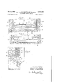
- Figure 5 is a sectional View showing a further modification.
- ⁇ A generally indicates a food storage cabinet including an insulated back wall I, insulated side walls '2, an insulated top wall 3, ⁇ an insulated bottom wall 4, and an insulated intermediate partition 5.
- the above mentioned walls and partitions ⁇ define two storage. compartments which are separated from and insulated from each other. i is an insulated door for the upper compartment and l an insulated door for the lower compartment. Thus the two. storage compartments are insulated from each other and. from the, outside air.
- Any Suitable gasketmg or sealing means 8 may be employed., it being understood that the details of the walls.I doors and sealing means do not of themselves form part of the present invention. Any suitable means may be employed for limiting to a mini.- mum heat transfer between the inside of the compartments and the outside air, and between they two compartments.
- the upper storage compartment B is preferably held at a relatively high temperature, as from 35 to 45 degrees Fahrenheit.
- TheA interior of the compartment C may be maintained at a tem-r perature substantially below freezing, as from 0 to l0 degrees in order lto adapt it for quick freezing and for cold storage of frozen goods.
- a sleeve including a vertical rear wall I I, side wall I2, a top wall I3 and a bottom wall I4.
- l5 indicates an evaporator coilv which may extend about three sides of the liner' or sleeve thus formed, namely about the rear wall II and each of the side walls I2.
- the length of the coil and the area of walls with which it is in Contact may be varied to cause the refrigerant to be evaporated at the desired temperature, preferably somewhatv above freezing, to prevent frost and to minimize dew formation on the walls, and to insure a suff'lciently vhigh relative humidity to prevent dehumidiflcation of stored food.
- the storage space of the compartment B is bounded at the bottom by an insulating food storage shelf I6 which is Shown as supported several inches above the bottom wall I4, of the upper sleeve. It is convenient to identify the space belowvthe insulating food shelf as the ice cubefOrming-andstOrage commeans and to design the gap from'shelf to wall partment E.
- a shelf including an evaporator coil I'I, this coil orV evaporator being in series with the evaporator I5.
- a restrictor 4I is interposed in the line 40 between evaporator I5 and evaporator I'I,-to reduce refrigerant pressure on evaporator II, which is thus made effective to freeze the contents of any suitable ice cube tray or trays I 8.
- Positioned below the evaporator II is any suitable defrosting.
- any suitable gap or gaps 2n may be ernployed between the insulating shelf I6 and the side walls and door of the compartment B. This air gap provides a connecting vapor path or paths between the compartment E and the compartment B, to permit excess water vapor to beV withdrawn from the air inY compartment B.
- the storage shelf I6 may be permanently fixed in relation ,v
- vIn compartment C is a liner sleeve toplwall 28., Asinthe'case ofV the upper sleeve,
- anyfsuitable evaporator .coil 29 V may extend about- Ythe sleeve," being Y'preferably exterior thereto but Yivnfheat transfer relationship. therewith..V
- the length and shape of the coil may be varied to suit. desired conditions but it may advantageously ex-V tend about the walls 25, 26 Yand 28,. beingpref-rI erably omitted from'the bottoml wall lI.H
- Vanysuitable means may be used.Vv VThe par-- ticlar .mechanisms -herein illustrated, however,
- suitablemeans may be employed for Vfeeding refrigerant. .
- the lower-sleeve is thus cooledto-a temperature from zero to plus 15 degrees Fahrenheit, and the evaporated refrigerant returns by the suction Yline 34 to thecompressorf30.
- "35 indicates any suitable motor for'the compressor ,'30, which may be controlledby any suitable ther-V mostatically operable switch 36, which may for, example include the bulb 31 in the-compartmentt'xv Y Y Q Y' f Tracing the circuit for the upper sleeve, the liquidV refrigerant is 'delivered through the restrictor tube 33a to the Vevaporator I5,'cooling that sleeve to a temperature between 35 and 45 degrees.
- the refrigerant is evaporated at such a pressure and corresponding temperature Yin evaporator I5, that the surface Aof the upper sleeve is kept at or above freezing, thus preventing the formation of frost andgminirniz-r includingVY the back wall 25, sidewalls 26, bottom wall 21 and.
- Refrigerant from the evaporator I5 flows through the return passage 4I) to any suitable restriction 4I, which causes a further pressure drop and consequent temperature drop in the refrigerant which thereafter flows through the passage 42 to the evaporator 'I'I and there evaporates at a temperature low enough to cause the freezing of ice cubes or other material in the compartment E.
- the evaporated refrigerant then returns along the return duct 43 to the compressor 30a.
- 44 indicates Va motor'for the compressor 30a, this motor being controlledby any suitable means such as for example the thermally operable switch 45 associated with the bulb 46 located at any suitable point in the upper compartment.
- the motors 35 and 44 may be employed to drive fans which circulate air through the individual condensers 32 and 32a, or a chimney, at therear. ofthe enclosing structure may beVV used. to. create an air.. current. through the.
- a double circuit condenser 50 is illustrated whichincludes separate condenser coils 5I and 52, onev being in 's circuit with the compressor 30 and the other with the vcompressor 30a, but-both coils associated.
- The, domestic refrigerator -of the usual type has an evaporator "serving'both to cool the food storage space andto freeze ice. To freeze ice the. evaporator must operate at aY refrigerant temperature so low as ⁇ to produce excessively dry airy
- the .relative humidity of the air to which food is exposed may run from 20 to 40% which dehydrates meats, fruits and vegetables.
- the ice freezing coil temperature selected for purposes both of controllingv humidity and of freezing ice at the required rate, isobtainecl by interposing a Xed restrictor lbetween the space cooling coil and the ice freezing coil, resulting in a temperature of sleeve surface at or slightly above 32 degrees and in the ice coil of from 10 to degrees, These vary during the cycle and with the conditions of loading.
- This construction we find it readily possible to hold the relative humidity at from 60 to 85% under widely varying ambient air conditions. At such humidities the liner wall may at times be moist when door openings are frequent in humid weather but at no time does it run down the wall or deposit on shelves or food.
- ice freezing shelf it is not essential that the ice freezing shelf be located at the bottom of the food storage chamber.
- An insulating housing around an ice freezing shelf or shelves at top or side, so arranged as to prevent interchange of air by convection currents but permitting vapor movement, will give the same control of humidity.
- the refrigerator described may be made alone or we may'combine it with a second food compartment, all within one insulated housing, refrigerated with a second expansion coil and condensing unit, holding a temperature below freezing for storage of frozen foods.
- the two refrigerating systems are wholly separate and independent in operation.
- variable restrictoi ⁇ instead of the fixed restrictor between Ithe space cooling and the ice freezing evaporators.
- the opening between the lower food shelf and l the outer walls may be varied in area by means such as dampers to permit the User t0 obtain variations in humidity.
- dampers to permit the User t0 obtain variations in humidity.
- We may also place the'ice freezingl shelf at the side or top of the food storage compartment, with an enclosure limiting or preventing cold air leaving the ice freezing compartment but maintaining the free movement of water vapor.
- Such variations are within the scope of this patent application.
- a refrigerator including a cabinet having two storage chambers thermally insulated from each other and from the outside, a single work chamber, two independent refrigerant condensing units in said work chamber. common means for maintaining a cooling circulation of air past both said condensing units, an evaporator effective in each storage chamber, two independent refrigerant circuits each including one of said evaporators and one of said condensing units, and
- an ice freezing evaporator in one of said storage compartments, in series with the evaporator of the same storage compartment.
- a refrigerator including a cabinet having two storage chambers thermally insulated from each other and from the outside, a single work chamber, two independent refrigerant condensing units in said work chamber, common means for maintaining a cooling circulation of air past both said condensing units, an evaporator effective in each storage chamber, two independent refrigerant circuits each including one of said evaporators and one of said condensing units, an ice freezing evaporator near the bottom of one of said storage chambers, in series with the evaporator of that chamber, and insulating partition means, in said storage chamber, above said ice freezing evaporator, adapted to define anice compartment and a food storage compartment within that chamber, there being communication between the twoV compartments .thus formed, adapted to provide water vapor transfer without air transfer between the compartments.
- a refrigerator having two storage chambersv thermally insulated from'each other and from the outside, a single work chamber, two independent Vrefrigerant condensing units in said work chamber, commonmeans for maintaining a cooling circulation of air past both said condensing units, an evaporator effective in each storage chamber, two independent refrigerant circuits each including one of said evaporators and one of said condensing units, an ice freezing evaporator near the bottom of one of said storage chambers, in series with one of said first mentioned evaporators, insulating partition means, in Y inside surface of said compartment, anice cube shelf within the compartment, an evaporator for said shelf, in series with and following said rst mentioned evaporator, a restrictor between said evaporators, adapted to reduce the pressure Aand temperature of the ice cube evaporator below the pressure and temperature of the first mentioned evaporator, and an insulating partition defining an ice cube'shelf zone within the compartment but
- a domestic refrigerator system a food storage compartment, an evaporator adapted to cool the upper inside surface of said Vcompartment, an ice cube shelf located near the bottom of the compartment, an evaporator for 'said shelf,
- a restrictor between said evaporators adapted to reduce the pressure and temperature of the ice cube evaporatorbelow the pressure and temperature of the first mentioned evaporator, means for delivering liquid refrigerant to the first evaporator and for withdrawing the evaporated refrigerant from the ice cube evaporator, and a partition located above the ice cube shelf and extending toward but spaced from the walls of the compartment, said partition having one or more gapsadapted to permit water vapor flow from the space above to the space below said partition.
- a food storage compartment 'an ⁇ evaporator adapted to cool the upper inside surface of said compartment, an ice cube shelf located near the bottom of the compartment, an evaporator for said shelf, in series with and following said rst mentioned evaporator, a restrictor between said evaporators, adapted to reducerth'e pressure and temperature of the ice cube evaporator below the pressure and temperature of the first mentioned evaporator, means for delivering liquid refrigerant to the first evaporator and for withdrawing evaporated refrigerant from the ice cube evaporator, a partition located above the ice cube shelf and extending toward but spaced from the walls of the compartment, said partition having one-or more gaps adapted to permit Water vaporV ow from the space above to the space below said partition, and
- a food storage compartment having a liner of heat conductive materiaLran evaporator constructed and arranged to cool the upper walls of said liner, a shelf adapted to receive ice cube trays, located adjacent the bottom of said compartment, an
Description
Jam 3, 1950 w. D. JORDAN ETAL 2,493,488
TWO-TEMPERATURE REFRIGERATOR, INCLUDING A HUMIDITY CONTROL SYSTEM Filed March 21, 1945 3 Sheets-Sheet 2 @PMA m Jan. 3, 1950 w. D. JORDAN ET AL 2,493,488
TWO-TEMPERATURE REFRIGERATOR, INCLUDING A HUMIDITY CONTROL SYSTEM Filed March 2l, 1945 l 3 Sheets-Sheet 3 bij Patented Jan. 3, 1950 TWO TEMPERATURE REFRIGERATOR, IN- CLUDING A HUMIDITY CONTROL SYSTEM Wayne D. Jordan, Chicago. and Paul D. Van
Vliet, Galesburg, Ill., assgnors to Liquid Carbonc Corporation, Chicago, Ill., a corporation of Delaware Application March` 21, 194,5, Serial No. 583,924 v (Cl. 621l6) 8 Claims. l
This invention relates to an improvement in. refrigerators and is adapted Yfor use in donlestlo` refrigerators.
One purposeI isY to provide an improved. two temperature refrigerator.
Another purpose is .tol provide a two temperature refrigerator having 'separate refrigerating means for a relatively high temperature and a low temperaturestorage space, the Storage spaces being separate, and insulated.
Another purpose is to provide improved means for controlling the relative humidity Of air in a refrigerator storage cabinet.
Another purpose is to provide improved means for freezing ice cubes and for at the same timev controlling the relative humidity of a refrigerator storage cabinet.l
vAnother purpose is to provide a refrigerator cabinet having means for freezing ice cubes in a relatively high temperature storage space without unduly dehydrating the foods in such storage space.
Another purpose is-to'provide a means of and method Yfor employing ice cube freezing means to control the relative humidity of a refrigerator storage space in which food is stored at temperatures above freezing.
Another purpose is to provide means for preventing excess humidity in a refrigeration storage cabinet in which the food is stored at temperatures above freezing.
Other purposes will appear from time to time in the course of the'specication and claims.
The invention 'is illustrated more or less diagrammatically yin Y the accompanying drawings wherein:
Figure 1 is a vertical section of a two temperature refrigerator; 1
Figure 2 is a section at the line 2--2 of Figure 1;
Figure 3 is a vsectional view showing a modification of Figure 1 Figure 4 is a section at the line 4-4 of Figure 3; and
Figure 5 is a sectional View showing a further modification.
Like parts are indicated by like symbols throughout the specification and drawings.
Referring'to the drawings,`A generally indicates a food storage cabinet including an insulated back wall I, insulated side walls '2, an insulated top wall 3,` an insulated bottom wall 4, and an insulated intermediate partition 5. The above mentioned walls and partitions` define two storage. compartments which are separated from and insulated from each other. i is an insulated door for the upper compartment and l an insulated door for the lower compartment. Thus the two. storage compartments are insulated from each other and. from the, outside air. Any Suitable gasketmg or sealing means 8 may be employed., it being understood that the details of the walls.I doors and sealing means do not of themselves form part of the present invention. Any suitable means may be employed for limiting to a mini.- mum heat transfer between the inside of the compartments and the outside air, and between they two compartments.
For convenience, the uppercompartment 15in.- dicated as B and the lower compartment as C'. Located below the lower compartment C 'isv an uninsulated space D for the condensing unit.
The upper storage compartment B is preferably held at a relatively high temperature, as from 35 to 45 degrees Fahrenheit. TheA interior of the compartment C may be maintained at a tem-r perature substantially below freezing, as from 0 to l0 degrees in order lto adapt it for quick freezing and for cold storage of frozen goods.
In the form of Figures l and following adual refrigerating system is employed having two separate refrigerant condensing units, with eva.1 io'` rators in circuit with each unit, there being' thus a complete and independent refrigeratingv system for each of the abovementioned storage corn-A partments.
Referring to the details of the compartmentsd it is advantageous to employ ar liner or sleeve of sheet metal for each compartment, with evapo-` rator coils on the exterior of each such sleeve, in heat transfer relationship therewith. In connection with the upper compartment B is indicated a sleeve including a vertical rear wall I I, side wall I2, a top wall I3 and a bottom wall I4. l5 indicates an evaporator coilv which may extend about three sides of the liner' or sleeve thus formed, namely about the rear wall II and each of the side walls I2. The length of the coil and the area of walls with which it is in Contact may be varied to cause the refrigerant to be evaporated at the desired temperature, preferably somewhatv above freezing, to prevent frost and to minimize dew formation on the walls, and to insure a suff'lciently vhigh relative humidity to prevent dehumidiflcation of stored food.. The storage space of the compartment B is bounded at the bottom by an insulating food storage shelf I6 which is Shown as supported several inches above the bottom wall I4, of the upper sleeve. It is convenient to identify the space belowvthe insulating food shelf as the ice cubefOrming-andstOrage commeans and to design the gap from'shelf to wall partment E. In the compartment E is illustrated a shelf including an evaporator coil I'I, this coil orV evaporator being in series with the evaporator I5. A restrictor 4I is interposed in the line 40 between evaporator I5 and evaporator I'I,-to reduce refrigerant pressure on evaporator II, which is thus made effective to freeze the contents of any suitable ice cube tray or trays I 8. Positioned below the evaporator II is any suitable defrosting.
pan I9. Any suitable gap or gaps 2n may be ernployed between the insulating shelf I6 and the side walls and door of the compartment B. This air gap provides a connecting vapor path or paths between the compartment E and the compartment B, to permit excess water vapor to beV withdrawn from the air inY compartment B. The storage shelf I6 may be permanently fixed in relation ,v
to the upper sleeve, with suitable'gapsY or apertures provided, or it may be removably mounted air gap. It will be understood however that any.
other suitable means may be employed for maintaining the desiredcontrol. Or, it may be advantageous to omit any such variable control to produce the desired average condition.
vIn compartment C is a liner sleeve toplwall 28., Asinthe'case ofV the upper sleeve,
anyfsuitable evaporator .coil 29 Vmay extend about- Ythe sleeve," being Y'preferably exterior thereto but Yivnfheat transfer relationship. therewith..V The length and shape of the coil may be varied to suit. desired conditions but it may advantageously ex-V tend about the walls 25, 26 Yand 28,. beingpref-rI erably omitted from'the bottoml wall lI.H
' With reference to the refrigerantY condensingunit, Vanysuitable means may be used.Vv VThe par-- ticlar .mechanisms -herein illustrated, however,
are ofthe mechanical type. With reference to their details, two compressorsV are employed, 33
yfor the lower sleeve and 30a for the upper sleeve.-
suitablemeans may be employed for Vfeeding refrigerant. .The lower-sleeve, is thus cooledto-a temperature from zero to plus 15 degrees Fahrenheit, and the evaporated refrigerant returns by the suction Yline 34 to thecompressorf30. "35 indicates any suitable motor for'the compressor ,'30, which may be controlledby any suitable ther-V mostatically operable switch 36, which may for, example include the bulb 31 in the-compartmentt'xv Y Y Q Y' f Tracing the circuit for the upper sleeve, the liquidV refrigerant is 'delivered through the restrictor tube 33a to the Vevaporator I5,'cooling that sleeve to a temperature between 35 and 45 degrees. Preferably the refrigerant is evaporated at such a pressure and corresponding temperature Yin evaporator I5, that the surface Aof the upper sleeve is kept at or above freezing, thus preventing the formation of frost andgminirniz-r includingVY the back wall 25, sidewalls 26, bottom wall 21 and.
.4 ing deposit of dew on the walls. Refrigerant from the evaporator I5 flows through the return passage 4I) to any suitable restriction 4I, which causes a further pressure drop and consequent temperature drop in the refrigerant which thereafter flows through the passage 42 to the evaporator 'I'I and there evaporates at a temperature low enough to cause the freezing of ice cubes or other material in the compartment E. The evaporated refrigerant then returns along the return duct 43 to the compressor 30a. 44 indicates Va motor'for the compressor 30a, this motor being controlledby any suitable means such as for example the thermally operable switch 45 associated with the bulb 46 located at any suitable point in the upper compartment.
With reference to Figure 1 it will be understood that the motors 35 and 44 may be employed to drive fans which circulate air through the individual condensers 32 and 32a, or a chimney, at therear. ofthe enclosing structure may beVV used. to. create an air.. current. through the.
condenser. In the form of Figure 5 a double circuit condenser 50 is illustrated whichincludes separate condenser coils 5I and 52, onev being in 's circuit with the compressor 30 and the other with the vcompressor 30a, but-both coils associated.
with a single fin structure. Y
' itwill be understood that under some circumstances it may be placed at the topor the side of the compartment, with any suitable enclosure means limiting interchange ofV air between compartments B and E through convection currents, but making possible the free movement of water vapor between the compartments. f
. It v.will be realized that, Whereas, a practical "andi operative device is described and illustrated,
nevertheless many changes may be made in the size, shape, number and Ydisposition of* parts without departing from the spirit ofthe invention. `.Therefore Ythe description. and drawings Y are tov be taken asin abroad sense illustrative or diagrammatic ratherlthan as limited Vto the precise showing. Y
The use and operation of the invention are as follows:
` The, domestic refrigerator -of the usual type has an evaporator "serving'both to cool the food storage space andto freeze ice. To freeze ice the. evaporator must operate at aY refrigerant temperature so low as `to produce excessively dry airy The .relative humidity of the air to which food is exposed may run from 20 to 40% which dehydrates meats, fruits and vegetables.
.To-avoid that dehydration it is the practice with some to cool the space by` means of a refrigerated liner surface,` the cool area being sufciently great so that the sleevey temperature need be only a few degrees below the wanted space temperature, witha minimum of around 32 degree's. perature` during *off-cycles of the 'condensing unit due to heat leakage'through insulation to.
the liner wall; Itmayrlse to 40 degrees or above. By this meansV much less moisture is condensed the relative humidity is therefore high;
j' Moisture entering with new air admitted whenY the door is vropened will condense as dew largely lon the coldest surfacesthe liner wall during the 'on-cycles-and will'partly'or wholly evaporate during off-cycles when thewall is warm. Theiextent ofthe evaporation will bev limited by This cold wall will assume a higher temthe time between onrcycles-,andthe relative vapor pressures between water on the cold wall and water in the air.
Should the cold Vwall rise to 40 degrees the vapor pressures Ywill come to balance at 100% humidity, providing suflicient time elapses for evaporation between on-cycles. Actually 'the cold wall may exceed 40 degrees.
With air at such high humidity there is certain to be condensation of moisture on Shelves and stored food at times when the temperature of the wet Wall is above that of the shelves and stored food. This creates an unsanitary condition and causes deterioration of meats and other foods. Another fault is that in humid weather sufficient moisture may enter with incoming air to cause Water to condense on and run down the side walls and pool on the liner floor. This also is unsanitary.
In our refrigerator weuse the cold wall means for space cooling, with the refrigerant coil external to but in thermal contact with the sleeve. To correct the faulty conditions mentioned we use the colder surface of the ice freezing evaporator to condense such water vapor as would cause a humidity above, say 85%.
We place the refrigerated ice cube freezing shelf near the floor of the liner and locate a storage shelf of W heat conductivity immediately above it. This storage shelf is dirnensioned t0 give an open space on all sides to permit water vapor to pass from the upper storage chamber to the cold shelf space.
AWe place the shelf at the bottom of the liner to prevent air interchange between the two spaces by convection, the colder air surrounding the ice freezing shelf being colder and there-fore denser. Water vapor, however, is free to pass downward under a head set up by the differential in vapor pressures above and below, and this vapor ow is controlled in amount by the size of the openings provided between the lower food shelf and surrounding walls,` as Well as by the refrigerant temperature maintained in the ice freezing coil.
The ice freezing coil temperature, selected for purposes both of controllingv humidity and of freezing ice at the required rate, isobtainecl by interposing a Xed restrictor lbetween the space cooling coil and the ice freezing coil, resulting in a temperature of sleeve surface at or slightly above 32 degrees and in the ice coil of from 10 to degrees, These vary during the cycle and with the conditions of loading. By this construction we find it readily possible to hold the relative humidity at from 60 to 85% under widely varying ambient air conditions. At such humidities the liner wall may at times be moist when door openings are frequent in humid weather but at no time does it run down the wall or deposit on shelves or food.
Food is not dehydrated and open storage of food is made possible, avoiding the loss of space occasioned by the use of covered containers.
It is not essential that the ice freezing shelf be located at the bottom of the food storage chamber. An insulating housing around an ice freezing shelf or shelves at top or side, so arranged as to prevent interchange of air by convection currents but permitting vapor movement, will give the same control of humidity.
The refrigerator described may be made alone or we may'combine it with a second food compartment, all within one insulated housing, refrigerated with a second expansion coil and condensing unit, holding a temperature below freezing for storage of frozen foods. In this case the two refrigerating systems are wholly separate and independent in operation.
Or we may use a single condenser structure having a single iin assembly but two separate refrigerant tube circuits, both in thermal contact with the same fins, this z-circuit condenser serving two otherwise independent refrigerating means.
We may also utilize a single condensing unit to refrigerate both sleeves in accordance with the system described in our co-pending application Serial No. 583,925, filed March 21, 1945, now Patent No. 2,462,240, granted Feb. 22, 1949, on a two temperature refrigerator system, in which case the warmer sleeve is controlled as to humidity exactly as described above.
Certain variations may be made in the design described above, as the use of a variable restrictoi` instead of the fixed restrictor between Ithe space cooling and the ice freezing evaporators. Or the opening between the lower food shelf and l the outer walls may be varied in area by means such as dampers to permit the User t0 obtain variations in humidity. We may also place the'ice freezingl shelf at the side or top of the food storage compartment, with an enclosure limiting or preventing cold air leaving the ice freezing compartment but maintaining the free movement of water vapor. Such variations are within the scope of this patent application.
We claim:
1. In a domestic refrigerator having two storage chambers thermally insulated from each other and from the outside, a single work chamber, two in dependent refrigerant condensing units in said work chamber, common means for maintaining a cooling circulation of air past both said condensing units, an evaporator eifective in each storage chamber, two independent refrigerant circuits each including one of said evaporators and one of said condensing units, and an ice freezing evaporator, in one of said storage compartments, in series with ,one of said first mentioned evaporators.V
2. In a refrigerator including a cabinet having two storage chambers thermally insulated from each other and from the outside, a single work chamber, two independent refrigerant condensing units in said work chamber. common means for maintaining a cooling circulation of air past both said condensing units, an evaporator effective in each storage chamber, two independent refrigerant circuits each including one of said evaporators and one of said condensing units, and
an ice freezing evaporator, in one of said storage compartments, in series with the evaporator of the same storage compartment.
3. In a refrigerator including a cabinet having two storage chambers thermally insulated from each other and from the outside, a single work chamber, two independent refrigerant condensing units in said work chamber, common means for maintaining a cooling circulation of air past both said condensing units, an evaporator effective in each storage chamber, two independent refrigerant circuits each including one of said evaporators and one of said condensing units, an ice freezing evaporator near the bottom of one of said storage chambers, in series with the evaporator of that chamber, and insulating partition means, in said storage chamber, above said ice freezing evaporator, adapted to define anice compartment and a food storage compartment within that chamber, there being communication between the twoV compartments .thus formed, adapted to provide water vapor transfer without air transfer between the compartments.
4. In a refrigerator having two storage chambersv thermally insulated from'each other and from the outside, a single work chamber, two independent Vrefrigerant condensing units in said work chamber, commonmeans for maintaining a cooling circulation of air past both said condensing units, an evaporator effective in each storage chamber, two independent refrigerant circuits each including one of said evaporators and one of said condensing units, an ice freezing evaporator near the bottom of one of said storage chambers, in series with one of said first mentioned evaporators, insulating partition means, in Y inside surface of said compartment, anice cube shelf within the compartment, an evaporator for said shelf, in series with and following said rst mentioned evaporator, a restrictor between said evaporators, adapted to reduce the pressure Aand temperature of the ice cube evaporator below the pressure and temperature of the first mentioned evaporator, and an insulating partition defining an ice cube'shelf zone within the compartment but adapted to permit communication' between that zone and the compartment, and means for controllingrsaid communication. v
6. In a domestic refrigerator system, a food storage compartment, an evaporator adapted to cool the upper inside surface of said Vcompartment, an ice cube shelf located near the bottom of the compartment, an evaporator for 'said shelf,
in series with and following Vsaid rst mentioned evaporator, a restrictor between said evaporators, adapted to reduce the pressure and temperature of the ice cube evaporatorbelow the pressure and temperature of the first mentioned evaporator, means for delivering liquid refrigerant to the first evaporator and for withdrawing the evaporated refrigerant from the ice cube evaporator, anda partition located above the ice cube shelf and extending toward but spaced from the walls of the compartment, said partition having one or more gapsadapted to permit water vapor flow from the space above to the space below said partition.
7. In a domestic refrigerator system, a food storage compartment, 'an` evaporator adapted to cool the upper inside surface of said compartment, an ice cube shelf located near the bottom of the compartment, an evaporator for said shelf, in series with and following said rst mentioned evaporator, a restrictor between said evaporators, adapted to reducerth'e pressure and temperature of the ice cube evaporator below the pressure and temperature of the first mentioned evaporator, means for delivering liquid refrigerant to the first evaporator and for withdrawing evaporated refrigerant from the ice cube evaporator, a partition located above the ice cube shelf and extending toward but spaced from the walls of the compartment, said partition having one-or more gaps adapted to permit Water vaporV ow from the space above to the space below said partition, and
means for varying the eiiective cross sectional area of said gaps.
8. In a domestic refrigerator system, a food storage compartment having a liner of heat conductive materiaLran evaporator constructed and arranged to cool the upper walls of said liner, a shelf adapted to receive ice cube trays, located adjacent the bottom of said compartment, an
evaporator arranged to cool said shelf, means for REFERENCES CITED The following references are of record the file of this patent: Y.
STATES PATENTS vNumber Name Date 2,102,354 Chambers Dec. 14, 1937 2,133,958 Kalischer Oct. 25, 1938 2,196,527 Hainsworth Apr. 9, 1940 2,215,372 Howeth Sept. 17, 1940 Y V2,242,407 VTobey May 20, 1941 `2,292,015 Schweller Aug. 4, 1942 Schweller May 18, 1943
Priority Applications (1)
| Application Number | Priority Date | Filing Date | Title |
|---|---|---|---|
| US583924A US2493488A (en) | 1945-03-21 | 1945-03-21 | Two temperature refrigerator, including a humidity control system |
Applications Claiming Priority (1)
| Application Number | Priority Date | Filing Date | Title |
|---|---|---|---|
| US583924A US2493488A (en) | 1945-03-21 | 1945-03-21 | Two temperature refrigerator, including a humidity control system |
Publications (1)
| Publication Number | Publication Date |
|---|---|
| US2493488A true US2493488A (en) | 1950-01-03 |
Family
ID=24335172
Family Applications (1)
| Application Number | Title | Priority Date | Filing Date |
|---|---|---|---|
| US583924A Expired - Lifetime US2493488A (en) | 1945-03-21 | 1945-03-21 | Two temperature refrigerator, including a humidity control system |
Country Status (1)
| Country | Link |
|---|---|
| US (1) | US2493488A (en) |
Cited By (38)
| Publication number | Priority date | Publication date | Assignee | Title |
|---|---|---|---|---|
| US2603071A (en) * | 1950-07-07 | 1952-07-15 | Thelma E Kalhoefer | Portable electric refrigerator |
| US2613509A (en) * | 1948-09-22 | 1952-10-14 | Nash Kelvinator Corp | Refrigerating apparatus |
| US2618936A (en) * | 1949-02-09 | 1952-11-25 | Kennedy Walter | Combination quick freeze and refrigerator cabinet |
| US2721454A (en) * | 1952-05-28 | 1955-10-25 | Levey Constance Dannenbaum | Dual compartment refrigerator with independent refrigerant liquefying means |
| DE949664C (en) * | 1953-10-21 | 1956-09-27 | Faere Armaturfabrik Ab | A refrigerator consisting of at least one refrigerator and at least one freezer |
| US2844945A (en) * | 1951-09-19 | 1958-07-29 | Muffly Glenn | Reversible refrigerating systems |
| US2927441A (en) * | 1956-01-16 | 1960-03-08 | Gen Motors Corp | Refrigerating apparatus with means preventing condensate on transparent panels |
| US3009336A (en) * | 1956-09-04 | 1961-11-21 | John R Bayston | Ice making machine |
| US3049892A (en) * | 1959-11-03 | 1962-08-21 | Muffly Glenn | Defrosting of evaporator |
| FR2468861A1 (en) * | 1979-11-05 | 1981-05-08 | Thomson Brandt | MOBILE ROOFING PARTITIONING DEVICE FOR REFRIGERATOR |
| FR2576676A1 (en) * | 1985-01-29 | 1986-08-01 | Selnor | REFRIGERATED CABINET WITH THREE COMPARTMENTS |
| US4976116A (en) * | 1988-07-28 | 1990-12-11 | Nihon Medix Co., Ltd. | Cold-air generating device |
| BE1004258A5 (en) * | 1990-08-13 | 1992-10-20 | Peter Rohner | Refrigerator compartment tempere. |
| US5375432A (en) * | 1993-12-30 | 1994-12-27 | Whirlpool Corporation | Icemaker in refrigerator compartment of refrigerator freezer |
| WO2003060395A1 (en) * | 2002-01-16 | 2003-07-24 | Eurochiller S.R.L. | Continuous automatic control system of industrial processes' cooling fluid |
| US6672092B2 (en) * | 2002-02-20 | 2004-01-06 | Stainless, Inc. | Countertop merchandiser unit with refrigerated and heated compartments and method thereof |
| US20050005426A1 (en) * | 2003-07-10 | 2005-01-13 | Sae Magnetics (H.K.) Ltd. | Manufacturing method of flying magnetic head slider |
| US20060260346A1 (en) * | 2005-05-18 | 2006-11-23 | Maytag Corporation | Refrigerator with improved water fill tube for ice maker |
| US20060260348A1 (en) * | 2005-05-18 | 2006-11-23 | Maytag Corporation | Refrigerator ice compartment latch |
| US20060260333A1 (en) * | 2005-05-18 | 2006-11-23 | Maytag Corporation | Insulated ice compartment for bottom mount refrigerator |
| US20060260342A1 (en) * | 2005-05-18 | 2006-11-23 | Maytag Corporation | Freeze tolerant waterline valve for a refrigerator |
| US20060266059A1 (en) * | 2005-05-27 | 2006-11-30 | Maytag Corporation | Insulated ice compartment for bottom mount refrigerator with controlled damper |
| FR2890159A1 (en) * | 2005-08-30 | 2007-03-02 | Entpr P Richardeau Soc Par Act | Upright refrigerator has at least one compartment connected to evaporation circuit to keep fruit and vegetables cool and fresh |
| US20070163282A1 (en) * | 2006-01-13 | 2007-07-19 | Cushman Robert L | Ice-making system for refrigeration appliance |
| US7284390B2 (en) | 2005-05-18 | 2007-10-23 | Whirlpool Corporation | Refrigerator with intermediate temperature icemaking compartment |
| US20080134707A1 (en) * | 2003-03-28 | 2008-06-12 | Lg Electronics Inc. | Refrigerator |
| US7392665B2 (en) | 2003-09-19 | 2008-07-01 | Lg Electronics Inc. | Refrigerator with icemaker |
| US7549297B2 (en) | 2005-05-18 | 2009-06-23 | Maytag Corporation | Refrigerator air control damper for ice compartment |
| US20090260371A1 (en) * | 2008-04-18 | 2009-10-22 | Whirlpool Corporation | Secondary cooling apparatus and method for a refrigerator |
| US20110232304A1 (en) * | 2010-03-24 | 2011-09-29 | Whirlpool Corporation | Systems and methods for multi-sense control algorithm for atomizers in refrigerators |
| US20120060545A1 (en) * | 2010-12-02 | 2012-03-15 | General Electric Company | Condenser assembly for multiple refrigeration systems |
| US20120067075A1 (en) * | 2010-09-16 | 2012-03-22 | Lg Electronics Inc. | Refrigerator |
| US20120085107A1 (en) * | 2010-03-12 | 2012-04-12 | Titan, Inc. | Heat transfer processes and equipment for industrial applications |
| US8408016B2 (en) | 2010-04-27 | 2013-04-02 | Electrolux Home Products, Inc. | Ice maker with rotating ice mold and counter-rotating ejection assembly |
| US20140007610A1 (en) * | 2012-07-06 | 2014-01-09 | Samsung Electronics Co., Ltd. | Refrigerator |
| WO2015062654A1 (en) * | 2013-10-31 | 2015-05-07 | Arcelik Anonim Sirketi | Heat exchanger assembly for a refrigeration appliance having independent heat exchange circuits |
| EP2696152A3 (en) * | 2012-07-06 | 2016-08-10 | Samsung Electronics Co., Ltd | Refrigerator and heat exchanger for the same |
| US10648713B2 (en) | 2017-02-08 | 2020-05-12 | Titan, Llc | Industrial heat transfer unit |
Citations (7)
| Publication number | Priority date | Publication date | Assignee | Title |
|---|---|---|---|---|
| US2102354A (en) * | 1933-05-16 | 1937-12-14 | Gen Motors Corp | Refrigeration |
| US2133958A (en) * | 1937-01-21 | 1938-10-25 | Westinghouse Electric & Mfg Co | Humidity control for refrigerators |
| US2196527A (en) * | 1934-11-15 | 1940-04-09 | Servel Inc | Refrigeration |
| US2215372A (en) * | 1940-09-17 | Refrigerating apparatus | ||
| US2242407A (en) * | 1939-10-19 | 1941-05-20 | Westinghouse Electric & Mfg Co | Refrigeration apparatus |
| US2292015A (en) * | 1940-09-26 | 1942-08-04 | Gen Motors Corp | Refrigerating apparatus |
| US2319522A (en) * | 1940-05-25 | 1943-05-18 | Gen Motors Corp | Refrigerating apparatus |
-
1945
- 1945-03-21 US US583924A patent/US2493488A/en not_active Expired - Lifetime
Patent Citations (7)
| Publication number | Priority date | Publication date | Assignee | Title |
|---|---|---|---|---|
| US2215372A (en) * | 1940-09-17 | Refrigerating apparatus | ||
| US2102354A (en) * | 1933-05-16 | 1937-12-14 | Gen Motors Corp | Refrigeration |
| US2196527A (en) * | 1934-11-15 | 1940-04-09 | Servel Inc | Refrigeration |
| US2133958A (en) * | 1937-01-21 | 1938-10-25 | Westinghouse Electric & Mfg Co | Humidity control for refrigerators |
| US2242407A (en) * | 1939-10-19 | 1941-05-20 | Westinghouse Electric & Mfg Co | Refrigeration apparatus |
| US2319522A (en) * | 1940-05-25 | 1943-05-18 | Gen Motors Corp | Refrigerating apparatus |
| US2292015A (en) * | 1940-09-26 | 1942-08-04 | Gen Motors Corp | Refrigerating apparatus |
Cited By (111)
| Publication number | Priority date | Publication date | Assignee | Title |
|---|---|---|---|---|
| US2613509A (en) * | 1948-09-22 | 1952-10-14 | Nash Kelvinator Corp | Refrigerating apparatus |
| US2618936A (en) * | 1949-02-09 | 1952-11-25 | Kennedy Walter | Combination quick freeze and refrigerator cabinet |
| US2603071A (en) * | 1950-07-07 | 1952-07-15 | Thelma E Kalhoefer | Portable electric refrigerator |
| US2844945A (en) * | 1951-09-19 | 1958-07-29 | Muffly Glenn | Reversible refrigerating systems |
| US2721454A (en) * | 1952-05-28 | 1955-10-25 | Levey Constance Dannenbaum | Dual compartment refrigerator with independent refrigerant liquefying means |
| DE949664C (en) * | 1953-10-21 | 1956-09-27 | Faere Armaturfabrik Ab | A refrigerator consisting of at least one refrigerator and at least one freezer |
| US2927441A (en) * | 1956-01-16 | 1960-03-08 | Gen Motors Corp | Refrigerating apparatus with means preventing condensate on transparent panels |
| US3009336A (en) * | 1956-09-04 | 1961-11-21 | John R Bayston | Ice making machine |
| US3049892A (en) * | 1959-11-03 | 1962-08-21 | Muffly Glenn | Defrosting of evaporator |
| EP0028559A2 (en) * | 1979-11-05 | 1981-05-13 | Selnor Societe D'electromenager Du Nord | Partition device with movable panels for cooling apparatus, and refrigerator comprising such a device |
| FR2468861A1 (en) * | 1979-11-05 | 1981-05-08 | Thomson Brandt | MOBILE ROOFING PARTITIONING DEVICE FOR REFRIGERATOR |
| EP0028559A3 (en) * | 1979-11-05 | 1982-06-30 | Thomson-Brandt | Partition device with movable panels for cooling apparatus, and refrigerator comprising such a device |
| FR2576676A1 (en) * | 1985-01-29 | 1986-08-01 | Selnor | REFRIGERATED CABINET WITH THREE COMPARTMENTS |
| EP0192526A1 (en) * | 1985-01-29 | 1986-08-27 | Societe D'electromenager Du Nord Selnor | Refrigerating cabinet with three compartments |
| US4976116A (en) * | 1988-07-28 | 1990-12-11 | Nihon Medix Co., Ltd. | Cold-air generating device |
| BE1004258A5 (en) * | 1990-08-13 | 1992-10-20 | Peter Rohner | Refrigerator compartment tempere. |
| CH681107A5 (en) * | 1990-08-13 | 1993-01-15 | Peter Rohner | |
| WO1993003316A1 (en) * | 1990-08-13 | 1993-02-18 | Peter Rohner | Warm section for a refrigerator |
| US5375432A (en) * | 1993-12-30 | 1994-12-27 | Whirlpool Corporation | Icemaker in refrigerator compartment of refrigerator freezer |
| WO2003060395A1 (en) * | 2002-01-16 | 2003-07-24 | Eurochiller S.R.L. | Continuous automatic control system of industrial processes' cooling fluid |
| US6672092B2 (en) * | 2002-02-20 | 2004-01-06 | Stainless, Inc. | Countertop merchandiser unit with refrigerated and heated compartments and method thereof |
| US20110197620A1 (en) * | 2003-03-28 | 2011-08-18 | Lg Electronics Inc. | Refrigerator |
| US7430873B2 (en) | 2003-03-28 | 2008-10-07 | Lg Electronics Inc. | Refrigerator |
| US8850843B2 (en) | 2003-03-28 | 2014-10-07 | Lg Electronics Inc. | Refrigerator |
| US8850842B2 (en) | 2003-03-28 | 2014-10-07 | Lg Electronics Inc. | Refrigerator |
| US7631514B2 (en) | 2003-03-28 | 2009-12-15 | Lg Electronics Inc. | Refrigerator |
| US7637119B2 (en) | 2003-03-28 | 2009-12-29 | Lg Electronics Inc. | Refrigerator |
| US7552597B2 (en) | 2003-03-28 | 2009-06-30 | Lg Electronics Inc. | Refrigerator |
| US8146379B2 (en) | 2003-03-28 | 2012-04-03 | Lg Electronics Inc. | Refrigerator |
| US20110197619A1 (en) * | 2003-03-28 | 2011-08-18 | Lg Electronics Inc. | Refrigerator |
| US7624591B2 (en) | 2003-03-28 | 2009-12-01 | Lg Electronics Inc. | Refrigerator |
| US20090151367A1 (en) * | 2003-03-28 | 2009-06-18 | Lg Electronics Inc. | Refrigerator |
| US7520139B2 (en) | 2003-03-28 | 2009-04-21 | Lg Electronics Inc. | Refrigerator |
| US7520138B2 (en) | 2003-03-28 | 2009-04-21 | Lg Electronics Inc. | Refrigerator |
| US7490475B2 (en) | 2003-03-28 | 2009-02-17 | Lg Electronics Inc. | Refrigerator |
| US20110100048A1 (en) * | 2003-03-28 | 2011-05-05 | Lg Electronics Inc. | Refrigerator |
| US7490474B2 (en) | 2003-03-28 | 2009-02-17 | Lg Electronics Inc. | Refrigerator |
| US7762098B2 (en) | 2003-03-28 | 2010-07-27 | Lg Electronics Inc. | Refrigerator |
| US7484382B2 (en) | 2003-03-28 | 2009-02-03 | Lg Electronics Inc. | Refrigerator |
| US7677055B2 (en) | 2003-03-28 | 2010-03-16 | Lg Electronics Inc. | Refrigerator |
| US20080134707A1 (en) * | 2003-03-28 | 2008-06-12 | Lg Electronics Inc. | Refrigerator |
| US7673470B2 (en) | 2003-03-28 | 2010-03-09 | Lg Electronics Inc. | Refrigerator |
| US20080203877A1 (en) * | 2003-03-28 | 2008-08-28 | Lg Electronics Inc. | Refrigerator |
| US20080216505A1 (en) * | 2003-03-28 | 2008-09-11 | Lg Electronics Inc. | Refrigerator |
| US20080216509A1 (en) * | 2003-03-28 | 2008-09-11 | Lg Electronics Inc. | Refrigerator |
| US20080216506A1 (en) * | 2003-03-28 | 2008-09-11 | Lg Electronics Inc. | Refrigerator |
| US20080223070A1 (en) * | 2003-03-28 | 2008-09-18 | Lg Electronics Inc. | Refrigerator |
| US20080224587A1 (en) * | 2003-03-28 | 2008-09-18 | Lg Electronics Inc. | Refrigerator |
| US7428820B2 (en) | 2003-03-28 | 2008-09-30 | Lg Electronics Inc. | Refrigerator |
| US8850841B2 (en) | 2003-03-28 | 2014-10-07 | Lg Electronics Inc. | Refrigerator |
| US20050005426A1 (en) * | 2003-07-10 | 2005-01-13 | Sae Magnetics (H.K.) Ltd. | Manufacturing method of flying magnetic head slider |
| US7392665B2 (en) | 2003-09-19 | 2008-07-01 | Lg Electronics Inc. | Refrigerator with icemaker |
| US7703298B2 (en) | 2003-09-19 | 2010-04-27 | Lg Electronics Inc. | Refrigerator with icemaker |
| US20100199702A1 (en) * | 2003-09-19 | 2010-08-12 | Lg Electronics Inc. | Refrigerator with icemaker |
| US20110107785A1 (en) * | 2003-09-19 | 2011-05-12 | Lg Electronics Inc. | Refrigerator with icemaker |
| US20110113811A1 (en) * | 2003-09-19 | 2011-05-19 | Lg Electronics Inc. | Refrigerator with icemaker |
| US20110113812A1 (en) * | 2003-09-19 | 2011-05-19 | Lg Electronics Inc. | Refrigerator with icemaker |
| US20110113813A1 (en) * | 2003-09-19 | 2011-05-19 | Lg Electronics Inc. | Refrigerator with icemaker |
| US7654105B2 (en) | 2003-09-19 | 2010-02-02 | Lg Electronics Inc. | Refrigerator with icemaker |
| US8601830B2 (en) | 2003-09-19 | 2013-12-10 | Lg Electronics Inc. | Refrigerator with icemaker |
| US8707728B2 (en) | 2003-09-19 | 2014-04-29 | Lg Electronics Inc. | Refrigerator with icemaker |
| US20060260342A1 (en) * | 2005-05-18 | 2006-11-23 | Maytag Corporation | Freeze tolerant waterline valve for a refrigerator |
| US20060260345A1 (en) * | 2005-05-18 | 2006-11-23 | Maytag Corporation | Refrigerator ice compartment with intermediate temperature |
| US7591141B2 (en) | 2005-05-18 | 2009-09-22 | Maytag Corporation | Electronic control system for insulated ice compartment for bottom mount refrigerator |
| US7594413B2 (en) | 2005-05-18 | 2009-09-29 | Maytag Corporation | Refrigerator ice compartment latch |
| US11486625B2 (en) | 2005-05-18 | 2022-11-01 | Whirlpool Corporation | Insulated ice compartment for bottom mount refrigerator with controlled damper |
| US10775092B2 (en) | 2005-05-18 | 2020-09-15 | Whirlpool Corporation | Insulated ice compartment for bottom mount refrigerator with controlled damper |
| US9879898B2 (en) | 2005-05-18 | 2018-01-30 | Whirlpool Corporation | Insulated ice compartment for bottom mount refrigerator with controlled damper |
| US7568354B2 (en) | 2005-05-18 | 2009-08-04 | Maytag Corporation | Refrigerator with improved water fill tube for ice maker |
| US7552594B2 (en) | 2005-05-18 | 2009-06-30 | Maytag Corporation | Refrigerator ice maker with improved air impingement |
| US7549297B2 (en) | 2005-05-18 | 2009-06-23 | Maytag Corporation | Refrigerator air control damper for ice compartment |
| US7458229B2 (en) | 2005-05-18 | 2008-12-02 | Maytag Corporation | Refrigerator with intermediate temperature icemaking compartment |
| US20080104977A1 (en) * | 2005-05-18 | 2008-05-08 | Coulter Tim L | Insulated ice compartment for bottom mount refrigerator |
| US20060260346A1 (en) * | 2005-05-18 | 2006-11-23 | Maytag Corporation | Refrigerator with improved water fill tube for ice maker |
| US7337620B2 (en) | 2005-05-18 | 2008-03-04 | Whirlpool Corporation | Insulated ice compartment for bottom mount refrigerator |
| US7726148B2 (en) | 2005-05-18 | 2010-06-01 | Maytag Corporation | Refrigerator ice compartment seal |
| US20080011011A1 (en) * | 2005-05-18 | 2008-01-17 | Maytag Corporation | Refrigerator with intermediate temperature icemaking compartment |
| US7287397B2 (en) | 2005-05-18 | 2007-10-30 | Whirlpool Corporation | Refrigerator with modular water tank assembly |
| US20100326102A1 (en) * | 2005-05-18 | 2010-12-30 | Maytag Corporation | Insulated ice compartment for bottom mount refrigerator with controlled damper |
| US20060260348A1 (en) * | 2005-05-18 | 2006-11-23 | Maytag Corporation | Refrigerator ice compartment latch |
| US20060260333A1 (en) * | 2005-05-18 | 2006-11-23 | Maytag Corporation | Insulated ice compartment for bottom mount refrigerator |
| US7568357B2 (en) | 2005-05-18 | 2009-08-04 | Maytag Corporation | Freeze tolerant waterline valve for a refrigerator |
| US7284390B2 (en) | 2005-05-18 | 2007-10-23 | Whirlpool Corporation | Refrigerator with intermediate temperature icemaking compartment |
| US8695370B2 (en) | 2005-05-18 | 2014-04-15 | Whirlpool Corporation | Refrigerator ice compartment with intermediate temperature |
| US20060260343A1 (en) * | 2005-05-18 | 2006-11-23 | Maytag Corporation | Refrigerator ice compartment latch and seal |
| US20060260347A1 (en) * | 2005-05-18 | 2006-11-23 | Maytag Corporation | Insulated ice compartment for bottom mount refrigerator |
| US20060260349A1 (en) * | 2005-05-18 | 2006-11-23 | Maytag Corporation | Refrigerator with modular water tank assembly |
| US20060260351A1 (en) * | 2005-05-18 | 2006-11-23 | Maytag Corporation | Refrigerator ice maker with improved air impingement |
| US20110000237A1 (en) * | 2005-05-27 | 2011-01-06 | Maytag Corporation | Insulated ice compartment for bottom mount refrigerator with controlled damper |
| US7607312B2 (en) | 2005-05-27 | 2009-10-27 | Maytag Corporation | Insulated ice compartment for bottom mount refrigerator with temperature control system |
| US7568359B2 (en) | 2005-05-27 | 2009-08-04 | Maytag Corporation | Insulated ice compartment for bottom mount refrigerator with controlled heater |
| US20060266061A1 (en) * | 2005-05-27 | 2006-11-30 | Maytag Corporation | Insulated ice compartment for bottom mount refrigerator with temperature control system |
| US20060266059A1 (en) * | 2005-05-27 | 2006-11-30 | Maytag Corporation | Insulated ice compartment for bottom mount refrigerator with controlled damper |
| US20110000238A1 (en) * | 2005-05-27 | 2011-01-06 | Maytag Corporation | Insulated ice compartment for bottom mount refrigerator with controlled damper |
| US7900465B2 (en) | 2005-05-27 | 2011-03-08 | Maytag Corporation | Insulated ice compartment for bottom mount refrigerator with controlled damper |
| FR2890159A1 (en) * | 2005-08-30 | 2007-03-02 | Entpr P Richardeau Soc Par Act | Upright refrigerator has at least one compartment connected to evaporation circuit to keep fruit and vegetables cool and fresh |
| US7681406B2 (en) | 2006-01-13 | 2010-03-23 | Electrolux Home Products, Inc. | Ice-making system for refrigeration appliance |
| US20070163282A1 (en) * | 2006-01-13 | 2007-07-19 | Cushman Robert L | Ice-making system for refrigeration appliance |
| US20090260371A1 (en) * | 2008-04-18 | 2009-10-22 | Whirlpool Corporation | Secondary cooling apparatus and method for a refrigerator |
| US8794026B2 (en) | 2008-04-18 | 2014-08-05 | Whirlpool Corporation | Secondary cooling apparatus and method for a refrigerator |
| US20120085107A1 (en) * | 2010-03-12 | 2012-04-12 | Titan, Inc. | Heat transfer processes and equipment for industrial applications |
| US9004369B2 (en) | 2010-03-24 | 2015-04-14 | Whirlpool Corporation | Systems and methods for multi-sense control algorithm for atomizers in refrigerators |
| US20110232304A1 (en) * | 2010-03-24 | 2011-09-29 | Whirlpool Corporation | Systems and methods for multi-sense control algorithm for atomizers in refrigerators |
| US8408016B2 (en) | 2010-04-27 | 2013-04-02 | Electrolux Home Products, Inc. | Ice maker with rotating ice mold and counter-rotating ejection assembly |
| US20120067075A1 (en) * | 2010-09-16 | 2012-03-22 | Lg Electronics Inc. | Refrigerator |
| US20120060545A1 (en) * | 2010-12-02 | 2012-03-15 | General Electric Company | Condenser assembly for multiple refrigeration systems |
| US20140007610A1 (en) * | 2012-07-06 | 2014-01-09 | Samsung Electronics Co., Ltd. | Refrigerator |
| EP2696152A3 (en) * | 2012-07-06 | 2016-08-10 | Samsung Electronics Co., Ltd | Refrigerator and heat exchanger for the same |
| US9726417B2 (en) * | 2012-07-06 | 2017-08-08 | Samsung Electronics Co., Ltd. | Refrigerator |
| WO2015062654A1 (en) * | 2013-10-31 | 2015-05-07 | Arcelik Anonim Sirketi | Heat exchanger assembly for a refrigeration appliance having independent heat exchange circuits |
| US10648713B2 (en) | 2017-02-08 | 2020-05-12 | Titan, Llc | Industrial heat transfer unit |
Similar Documents
| Publication | Publication Date | Title |
|---|---|---|
| US2493488A (en) | Two temperature refrigerator, including a humidity control system | |
| US2345453A (en) | Refrigeration | |
| US2487182A (en) | Two-temperature refrigerator having means for defrosting | |
| US2728203A (en) | Refrigerator having a freezer compartment in the door | |
| US2416777A (en) | Multiple temperature refrigerator | |
| US2481616A (en) | Refrigerator | |
| US3050955A (en) | Multi-temperature refrigerator | |
| US2478312A (en) | Refrigerator, including an evaporator and ice cube tray arrangement for cooling the food storage compartment | |
| US2065604A (en) | Refrigerating apparatus | |
| US2944410A (en) | Refrigerating apparatus | |
| US2692482A (en) | Multitemperature refrigerator | |
| US2442978A (en) | Refrigeration apparatus having frost localizing means | |
| US2663999A (en) | Household refrigerator | |
| US2291559A (en) | Refrigerating apparatus | |
| US1979638A (en) | Refrigerating apparatus | |
| US2329139A (en) | Refrigerating apparatus | |
| US2859595A (en) | Two temperature refrigerator with forced air circulation | |
| US3048024A (en) | Refrigerating apparatus | |
| US2672023A (en) | Two-temperature refrigerating apparatus | |
| US2432931A (en) | Refrigerated evaporator shelf | |
| US2219789A (en) | Refrigerator | |
| US2446636A (en) | Refrigeration | |
| US2442188A (en) | Controlled humidity refrigerator | |
| US2909910A (en) | Refrigerating apparatus | |
| US2430456A (en) | Two-temperature refrigerator |