US2760228A - Manufacture of tubular insulators for electric conductors - Google Patents
Manufacture of tubular insulators for electric conductors Download PDFInfo
- Publication number
- US2760228A US2760228A US337105A US33710553A US2760228A US 2760228 A US2760228 A US 2760228A US 337105 A US337105 A US 337105A US 33710553 A US33710553 A US 33710553A US 2760228 A US2760228 A US 2760228A
- Authority
- US
- United States
- Prior art keywords
- belts
- conductor
- tube
- extruded
- pressure
- Prior art date
- Legal status (The legal status is an assumption and is not a legal conclusion. Google has not performed a legal analysis and makes no representation as to the accuracy of the status listed.)
- Expired - Lifetime
Links
Images


Classifications
-
- B—PERFORMING OPERATIONS; TRANSPORTING
- B29—WORKING OF PLASTICS; WORKING OF SUBSTANCES IN A PLASTIC STATE IN GENERAL
- B29C—SHAPING OR JOINING OF PLASTICS; SHAPING OF MATERIAL IN A PLASTIC STATE, NOT OTHERWISE PROVIDED FOR; AFTER-TREATMENT OF THE SHAPED PRODUCTS, e.g. REPAIRING
- B29C49/00—Blow-moulding, i.e. blowing a preform or parison to a desired shape within a mould; Apparatus therefor
- B29C49/0015—Making articles of indefinite length, e.g. corrugated tubes
- B29C49/0021—Making articles of indefinite length, e.g. corrugated tubes using moulds or mould parts movable in a closed path, e.g. mounted on movable endless supports
-
- H—ELECTRICITY
- H01—ELECTRIC ELEMENTS
- H01B—CABLES; CONDUCTORS; INSULATORS; SELECTION OF MATERIALS FOR THEIR CONDUCTIVE, INSULATING OR DIELECTRIC PROPERTIES
- H01B13/00—Apparatus or processes specially adapted for manufacturing conductors or cables
- H01B13/06—Insulating conductors or cables
- H01B13/18—Applying discontinuous insulation, e.g. discs, beads
- H01B13/185—Applying discontinuous insulation, e.g. discs, beads by periodically constricting an insulating sleeve
-
- B—PERFORMING OPERATIONS; TRANSPORTING
- B29—WORKING OF PLASTICS; WORKING OF SUBSTANCES IN A PLASTIC STATE IN GENERAL
- B29L—INDEXING SCHEME ASSOCIATED WITH SUBCLASS B29C, RELATING TO PARTICULAR ARTICLES
- B29L2023/00—Tubular articles
- B29L2023/003—Tubular articles having irregular or rough surfaces
Definitions
- Insulation means are already known, in which an insulating tube is disposed about an electric conductor and is simultaneously constricted at intervals in such manner as to grip the said conductor and to form an insulation having air spaces by which the dielectric properties are improved.
- the conductor thus insulated may be employed as the central conductor of a coaxial pair for telecommunications. It may also be employed for the production of symmetrical pairs or quads for aerial feeders or it may be employed in any other electrical circuit.
- constricted parts have the object of maintaining the conductor in the centre of the tubular insulator and may form grooves which secure the conductor in position and also provide a fluid-tight partitioning which is capable of preventing accidental circulation of water within the said tubular insulator.
- the known devices for producing such insulators consist of fixed or movable jaws disposed at intervals and produce constrictions when closed.
- they do not give perfect results and also are capable of treating only such materials as paper or unvulcanised rubber, that is, materials having a certain rigidity, whereas if a method of this nature is applied to very plastic materials leaving an extrusion machine, for example polyethylene plastics, the intermediate tubular portions between the constricted parts yield and become flattened and deformed, and the result obtained is very bad.
- the apparatus according to the present invention overcomes these serious disadvantages.
- an apparatus for the continuous shaping of an extruded insulating plastic tube for an electric conductor which is formed around the said conductor during the hardening of the extruded material, wherein there are employed a plurality of endless belts of rubber or plastic material having moulded bosses thereon and further provided with gear teeth for maintaining the said bosses in a suitable position in relation to one another and for driving the said belts by a sprocket wheel mechanism the said conductor being fed with a continuous movement between the said belts and at a linear speed equal to that of the said belts, while a gas pressure is maintained within the said tube in order to ensure the application of its outer surface against the said bosses, the said belts forming, in those of their parts which are in contact with one another, a continuous mold surrounding the said tube.
- the operation is effected with a cooling action, and if vulcanisable material, such as rubber or thermosetting material is employed, the said operation is effected in an enclosed space which is heated throughout the period necessary for the conversion of the soft material into hardened product.
- Figure 1 illustrates the general known form of a conductor provided with a tubular insulation of the type obtained by means of the apparatus according to the present invention
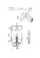
- FIGS. 2 and 3 illustrate the apparatus for the manufacture of insulation in accordance with the present invention
- FIGs 4 and 5 illustrate details of the construction of the apparatus as illustrated in Figure 2,
- FIGs 6, 7, 8 and 9 illustrate by way of example new forms of tubular insulation which can be obtained by means of the apparatus as illustrated in Figures 2 and 3.
- the dies for the formation of the bosses consist of endless belts of rubber or molded plastic material such as that indicated at 3.
- the bosses which produce the constrictions or depressions in the preextruded tube are formed by moulding on the said belts, such as illustrated at 4 in Figure 3.
- the belts 3 are maintained in guideways 5 and are pressed one against the other in such manner as to form the boss 4, which is an envelope of the product to be obtained.
- the product is formed as the belts travel forward, the said belts 3 gripping and carrying along the tube extruded around the conductor 6.
- the belts 3 are driven through gear wheels 8 by means of a driving mechanism not illustrated in the accompanying drawings.
- the conductor 6 travels between the belts with a continuous linear movement on leaving the extrusion machine, by which the material is injected around the said conductor.
- the plastic material is injected in the form of a tube by the said extrusion machine, which is partially illustrated at 10 in Figure 2, and the tube thus formed, while still in the plastic condition, then passes between the bosses on the belts 3 and continues its movement so as finally to leave the machine at the same time as the conductor on which it is secured.
- Figure 3 illustrates the formation of the complete boss 4 formed by the pressure of the belts one against the other and their simultaneous travel.
- the moulded teeth 7 may be replaced by a metal chain enclosed in the plastic material of which the belt is formed.
- the said gears 8 or sprocket wheels are mechanically coupled together in such manner that the boss portions situated on the said belts are always in corresponding positions to one another.
- the said belts may be driven by a mechanical driving system adapted in particular to vary the speed of forward movement. Consequently, the speed of production of the extruded article will bedetermined by the said mechanical I
- the choice between these driving means depends upon the dimensions of, the extruded product and the available space.
- the said pressure which is of the order of several grammes per square centimetre, ensures constancy of the external form of the extruded and. formed insulator.
- FIG 4 there: is illustrated a nozzle 12 which en closes the extruded. tube from the instant when it leaves the extrusion machine until it enters the boss forming belts.
- the pressure within this nozzle 12 and Within the inlet 11 is regulated by a pressure reducing valve 13 and gauged by a manometer 14.
- Figure 5 illustrated a modifiedconstruction of the arrangement illustrated in Figure 4, thismodification being applicable in cases where it is desirable to establisha slight pressure ditference between the inlet' 11 and the nozzle 12 by reason of the pressure loss occurring in the passage of the air (or-other gas) from the inlet 11 to the interior of the extruded tube.
- the pressures are individually regulated by the pressure reducing valves 131 and 132 and gauged by the manometers 141 and 142.
- the air under pressure may naturally be replaced by any inert gas, such for example as nitrogen.
- the hardening When the extruded insulation is a thermoplastic material, the hardening must be complete beforeitleaves the boss forming belts, and both these belts may therefore be steeped in a water-cooling tank or in a; tank' provided must be of such length as to allow for the time required for the conversion of the material.
- the number of belts employed istwo, but this number may be increased, for example to three. or four, each belt comprising a corresponding moulding boss element.
- Figures 6, 7, 8 and 9 illustrate by way of example novel and advantageous. forms of insulation for a central conductor, which forms can be produced by the method hereinbefore described from a tube of extruded plastic material, simultaneously with the extruding operation. These forms of insulation may be employed with advantage to insulate and support the central conductor of a coaxial pair or conductors of balanced pairs or quads.
- Figure 6 illustrates such an insulation manufactured from an extruded polyethylene tube around the central conductor of a coaxial pair.
- the extruded tube has an external diameter substantially equal to the internal diameter of the tubular return conductor'of the said pair.
- depressions 15 are formed with the aid of the apparatus hereinbefore described, the said depressions having the object of maintaining the conductor in position.
- the quantity ofinsulation situated in the neighbourhood of the conductor is very small, which is advantageous from the viewpoint of the transmission of high-frequency currents.
- Figure 7 illustrates a modification of this arrangement, in which depressions 16 are transverse instead of longitudinal and are situated face to face in pairs.
- the samedepressions could be distributed along a helical line.
- Figures 8 and 9 illustrate another arrangement in which a tube of polyethylene is extruded around the conductor and thereafter flattened at intervals by small bosses in the form of jaws situated on the boss forming belts 3;
- d Witha given diameter D, d will preferably be so chosen that:
- the described insulated conductors may not only be employed as the central conductor of a coaxial pair, but may also advantageously be employed to produce telephone pairs or quads formed by'stranding together either two or four insulated conductors as hereinbeforc described.
- The' described apparatus may also be employed for moulding operations and uses other than those hereinbefore described and may be employed for the continuous shaping of any extruded plastic product. Only the bass provided on the belts would be correspondingly modified.
- this apparatus may be employed for the insulation of conductors covered with an insulator of a cellular texture of the foam or sponge type.
- the insulating product such for example as polyethylene or polystyrene
- the extrusion machine with a gas under pressure or with substances which liberate inert gases under the action of temperature.
- the hot-extruded product then has the appearance of a foam and has unstable dimensions because it always tends to expand under the action of the internal pressure of the. gases by which the multiple cells are filled.
- Apparatus similar to those hereinbefore described with reference to Figures 4 and 5 may then be employed with advantage in order to prevent expansion of the cells as they pass from the extrusion machine to the point of admission into the forming belts.
- An apparatus for the continuous shaping of tube formed insulating plastic material around an electric conductor during the hardening of said material comprising a device for extruding plastic material in a relatively soft state so as to form a tube around said conductor, a plurality of endless belts of elastic material in close contact with each other over a substantial part of their length and each having moulding bosses thereon and further provided with gear teeth for maintaining said bosses in a suitable position in relation to one another and for driving said belts by a sprocket wheel mechanism, said belts forming over said length a closed moulding cavity around said conductor, means for driving said conductor with a continuous movement between said belts at a linear speed equal to that of said belts, means for applying a gas pressure inside said tube, a nozzle through which said conductor is drawn outside said extruding device previously to its being driven between said belts, said nozzle leaving a substantial free space around said conductor and extruded tube, and means for applying in said free space a gas pressure substantially equal to that
- Apparatus as claimed in claim 1 comprising tubings for introducing into both said extruding device and nozzle a gas pressure controlled by a common regulating valve.
- Apparatus as claimed in claim 1 comprising tubings for introducing into said extruding device and nozzle separately controllable gas pressures controlled by individual regulating valves.
- a pressure device comprising a first pressure source for introducing a pressure medium between said first and second materials for spacing said materials, a second pressure source for applying a pressure medium to said first material in opposition to the force of the pressure medium applied between said materials, and pressure regulating means to control the pressures applied by said first and second pressure sources to control distortion of the first material.
Description
Aug. 28, 1956 P. F. VERGES MANUFACTURING OF TUBULAR INSULATORS FOR ELECTRIC CONDUCTORS Filed Feb. 16, 1953 3 Sheets-Sheet l Aug. 28, 1956 P. F. VERGES MANUFACTURING OF TUBULAR INSULATORS FOR ELECTRIC CONDUCTORS Filed Feb. 16, 1953 3 Sheets-Sheet 2 Aug. 28, 1956 P. F. VERGES 2,7
MANUFACTURING OF TUBULAR INSULATORS FOR ELECTRIC CONDUCTORS Filed Feb. 16, 195:5 3 Sheets-Sheet 3 Fig.7
United States Patent Ofilice 2,760,228 Patented Aug. 28, 1955 MANUFACTURE OF TUBULAR INSULATORS FOR ELECTRIC CQNDUCTORS Paul Frangois Vergs, N euilly-sur-Seine, France, assignor to Socrete Anonyme de Telecommunications, Paris, France Application February 16, 1953, Serial No. 337,105 Claims priority, application France February 19, 1952 6 Claims. (Cl. 18-13) This invention is for improvements in or relating to the manufacture of tubular insulators for electric conductors.
Insulation means are already known, in which an insulating tube is disposed about an electric conductor and is simultaneously constricted at intervals in such manner as to grip the said conductor and to form an insulation having air spaces by which the dielectric properties are improved.
The conductor thus insulated may be employed as the central conductor of a coaxial pair for telecommunications. It may also be employed for the production of symmetrical pairs or quads for aerial feeders or it may be employed in any other electrical circuit.
It is also known that the constricted parts have the object of maintaining the conductor in the centre of the tubular insulator and may form grooves which secure the conductor in position and also provide a fluid-tight partitioning which is capable of preventing accidental circulation of water within the said tubular insulator.
The known devices for producing such insulators consist of fixed or movable jaws disposed at intervals and produce constrictions when closed. However, they do not give perfect results and also are capable of treating only such materials as paper or unvulcanised rubber, that is, materials having a certain rigidity, whereas if a method of this nature is applied to very plastic materials leaving an extrusion machine, for example polyethylene plastics, the intermediate tubular portions between the constricted parts yield and become flattened and deformed, and the result obtained is very bad. The apparatus according to the present invention overcomes these serious disadvantages.
According to the present invention there is provided an apparatus for the continuous shaping of an extruded insulating plastic tube for an electric conductor, which is formed around the said conductor during the hardening of the extruded material, wherein there are employed a plurality of endless belts of rubber or plastic material having moulded bosses thereon and further provided with gear teeth for maintaining the said bosses in a suitable position in relation to one another and for driving the said belts by a sprocket wheel mechanism the said conductor being fed with a continuous movement between the said belts and at a linear speed equal to that of the said belts, while a gas pressure is maintained within the said tube in order to ensure the application of its outer surface against the said bosses, the said belts forming, in those of their parts which are in contact with one another, a continuous mold surrounding the said tube.
If polyethylene or any other thermoplastic product is employed, the operation is effected with a cooling action, and if vulcanisable material, such as rubber or thermosetting material is employed, the said operation is effected in an enclosed space which is heated throughout the period necessary for the conversion of the soft material into hardened product.
The present invention will be more particularly described with reference to the accompanying drawings in which:
Figure 1 illustrates the general known form of a conductor provided with a tubular insulation of the type obtained by means of the apparatus according to the present invention,
Figures 2 and 3 illustrate the apparatus for the manufacture of insulation in accordance with the present invention,
Figures 4 and 5 illustrate details of the construction of the apparatus as illustrated in Figure 2, and
Figures 6, 7, 8 and 9 illustrate by way of example new forms of tubular insulation which can be obtained by means of the apparatus as illustrated in Figures 2 and 3.
Referring to the drawings and in particular to the apparatus illustrated in Figure 2, the dies for the formation of the bosses consist of endless belts of rubber or molded plastic material such as that indicated at 3. The bosses which produce the constrictions or depressions in the preextruded tube are formed by moulding on the said belts, such as illustrated at 4 in Figure 3.
The belts 3 are maintained in guideways 5 and are pressed one against the other in such manner as to form the boss 4, which is an envelope of the product to be obtained. The product is formed as the belts travel forward, the said belts 3 gripping and carrying along the tube extruded around the conductor 6. The belts 3 are driven through gear wheels 8 by means of a driving mechanism not illustrated in the accompanying drawings.
The conductor 6 travels between the belts with a continuous linear movement on leaving the extrusion machine, by which the material is injected around the said conductor. The plastic material is injected in the form of a tube by the said extrusion machine, which is partially illustrated at 10 in Figure 2, and the tube thus formed, while still in the plastic condition, then passes between the bosses on the belts 3 and continues its movement so as finally to leave the machine at the same time as the conductor on which it is secured.
Figure 3 illustrates the formation of the complete boss 4 formed by the pressure of the belts one against the other and their simultaneous travel.
In order to maintain continuous correspondence between the boss portions situated on the belts, that face of the belts which lies opposite the bosses is provided with teeth 7 adapted to engage with gears 8 which control the travel of the said belts.
The moulded teeth 7 may be replaced by a metal chain enclosed in the plastic material of which the belt is formed.
The said gears 8 or sprocket wheels are mechanically coupled together in such manner that the boss portions situated on the said belts are always in corresponding positions to one another.
The said belts may be driven by a mechanical driving system adapted in particular to vary the speed of forward movement. Consequently, the speed of production of the extruded article will bedetermined by the said mechanical I The choice between these driving means depends upon the dimensions of, the extruded product and the available space.
In order to ensure that the extruded product takes the form of the external envelope formed by the bosses provided on the belts, by which envelope the product is given its final form after hardening, air pressure is applied to the interior ofthe extruded tube. This air pressure is supplied through an inlet 11 situated, on the side from which the conductor enters, within the extrusion machine, the said conductor passing through the said inlet.
The said pressure, which is of the order of several grammes per square centimetre, ensures constancy of the external form of the extruded and. formed insulator.
Should it be desired to obtain an insulation having a small thickness it is advantageous to create around the extruded tube, until it is introduced into the belts, a pressure substantially. equal to. that: introduced into the interior of the said tube.
The injection device necessary for this purpose is illustrated in Figures 4 and. 5..
In Figure 4 there: is illustrated a nozzle 12 which en closes the extruded. tube from the instant when it leaves the extrusion machine until it enters the boss forming belts. The pressure within this nozzle 12 and Within the inlet 11 is regulated by a pressure reducing valve 13 and gauged by a manometer 14.
Figure 5 illustrated a modifiedconstruction of the arrangement illustrated in Figure 4, thismodification being applicable in cases where it is desirable to establisha slight pressure ditference between the inlet' 11 and the nozzle 12 by reason of the pressure loss occurring in the passage of the air (or-other gas) from the inlet 11 to the interior of the extruded tube. In this case, the pressures are individually regulated by the pressure reducing valves 131 and 132 and gauged by the manometers 141 and 142.
It is known that the constancy of the external dimensions of the insulator is of great importance in some cases, for example, in the manufacture of aninsulated central conductor of a coaxial pair, because it is these dimensions which determine those of the external return conductor, which will subsequently bear against the surface of the insulator, and it is known that disturbances in the transmission of high-frequency currents may occur if the diameter of the return conductor is not constant; The required precision in these dimensions will be obtained under good conditions by the method according to the present invention and will depend solely upon the accuracy With which the bosses are formed on the belts. These will therefore have to be designed and shaped with care in metallic moulds consisting of one or more elements.
The air under pressure may naturally be replaced by any inert gas, such for example as nitrogen.
When the extruded insulation is a thermoplastic material, the hardening must be complete beforeitleaves the boss forming belts, and both these belts may therefore be steeped in a water-cooling tank or in a; tank' provided must be of such length as to allow for the time required for the conversion of the material.
If a long train of belts is required, there may be disposed between the gears 8, other gears synchronised therewith, the object of which is to maintain the bosses provided on the belts in corresponding positions and to compensate for the elasticity of the material of which the said belts consist.
In Figure 2, the number of belts employed istwo, but this number may be increased, for example to three. or four, each belt comprising a corresponding moulding boss element.
It is possible to regulate the. gripping action exerted by the belts 3 with the aid. of any mechanical locking gear-s8, and consequently on the pressure exerted by the belts. There is illustrated in- Figure 2 one of the control members 9 for this locking device, which may also be adapted to enable the belts 3 to be completely removed for cleaning.
Figures 6, 7, 8 and 9 illustrate by way of example novel and advantageous. forms of insulation for a central conductor, which forms can be produced by the method hereinbefore described from a tube of extruded plastic material, simultaneously with the extruding operation. These forms of insulation may be employed with advantage to insulate and support the central conductor of a coaxial pair or conductors of balanced pairs or quads.
Figure 6 illustrates such an insulation manufactured from an extruded polyethylene tube around the central conductor of a coaxial pair. The extruded tube has an external diameter substantially equal to the internal diameter of the tubular return conductor'of the said pair.
While the extruded tube is still plastic, depressions 15 are formed with the aid of the apparatus hereinbefore described, the said depressions having the object of maintaining the conductor in position. In this arrangement, the quantity ofinsulation situated in the neighbourhood of the conductor is very small, which is advantageous from the viewpoint of the transmission of high-frequency currents.
Figure 7 illustrates a modification of this arrangement, in which depressions 16 are transverse instead of longitudinal and are situated face to face in pairs. In another arrangement, the samedepressions could be distributed along a helical line.
Figures 8 and 9 illustrate another arrangement in which a tube of polyethylene is extruded around the conductor and thereafter flattened at intervals by small bosses in the form of jaws situated on the boss forming belts 3;
In Figures- 8 and 9, the flattening is effected alternately in planes perpendicular to one another. In this arrangement, the quantity of insulating material is reduced in relation to that employed'in the arrangement illustrated in Figures 1 and 4, because the diameter :1 of the extruded tube is then smaller than the internal diameter D of the return conductor, which will subsequently be applied to the exterior of the insulating tube.
Witha given diameter D, d will preferably be so chosen that:
The described insulated conductors may not only be employed as the central conductor of a coaxial pair, but may also advantageously be employed to produce telephone pairs or quads formed by'stranding together either two or four insulated conductors as hereinbeforc described.
The' described apparatus may also be employed for moulding operations and uses other than those hereinbefore described and may be employed for the continuous shaping of any extruded plastic product. Only the bass provided on the belts would be correspondingly modified.
In particular, again with a view to uses for tcie-communication purposes, this apparatus may be employed for the insulation of conductors covered with an insulator of a cellular texture of the foam or sponge type.
In such' a covering, the insulating product, such for example as polyethylene or polystyrene, is mixed in the extrusion machine with a gas under pressure or with substances which liberate inert gases under the action of temperature.
The hot-extruded product then has the appearance of a foam and has unstable dimensions because it always tends to expand under the action of the internal pressure of the. gases by which the multiple cells are filled.
It is consequently difiicult to obtain an external contour of exact dimensions, which is frequently a serious disadvantage, particularly in the case of insulated conductors for telecommunications.
The apparatus described and illustrated in Figures 2 and 3 may be employed with advantage in this case because the external contour :of the extruded cellular material Will be maintained in close contact with the interior of the boss forming belts 3 during its cooling.
Apparatus similar to those hereinbefore described with reference to Figures 4 and 5 may then be employed with advantage in order to prevent expansion of the cells as they pass from the extrusion machine to the point of admission into the forming belts.
What is claimed is:
1. An apparatus for the continuous shaping of tube formed insulating plastic material around an electric conductor during the hardening of said material, comprising a device for extruding plastic material in a relatively soft state so as to form a tube around said conductor, a plurality of endless belts of elastic material in close contact with each other over a substantial part of their length and each having moulding bosses thereon and further provided with gear teeth for maintaining said bosses in a suitable position in relation to one another and for driving said belts by a sprocket wheel mechanism, said belts forming over said length a closed moulding cavity around said conductor, means for driving said conductor with a continuous movement between said belts at a linear speed equal to that of said belts, means for applying a gas pressure inside said tube, a nozzle through which said conductor is drawn outside said extruding device previously to its being driven between said belts, said nozzle leaving a substantial free space around said conductor and extruded tube, and means for applying in said free space a gas pressure substantially equal to that applied inside said tube.
2. Apparatus as claimed in claim 1 wherein said belts are of rubber.
3. Apparatus as claimed claim 1 wherein said belts are of plastic material.
4. Apparatus as claimed in claim 1, comprising tubings for introducing into both said extruding device and nozzle a gas pressure controlled by a common regulating valve.
5. Apparatus as claimed in claim 1, comprising tubings for introducing into said extruding device and nozzle separately controllable gas pressures controlled by individual regulating valves.
6. In a tube forming device wherein a first material is extruded around a second material; a pressure device comprising a first pressure source for introducing a pressure medium between said first and second materials for spacing said materials, a second pressure source for applying a pressure medium to said first material in opposition to the force of the pressure medium applied between said materials, and pressure regulating means to control the pressures applied by said first and second pressure sources to control distortion of the first material.
References Cited in the file of this patent UNITED STATES PATENTS 2,075,735 Loomis Mar. 30, 1937 2,291,670 Wiley et al Aug. 4, 1942 2,395,920 Te Grotenhuis Mar. 5, 1946 2,575,138 Slaughter Nov. 13, 1951 2,593,469 Mason Apr. 22, 1952 2,654,124 Layte Oct. 6, 1953 FOREIGN PATENTS 657,643 Great Britain Sept. 26, 1951
Applications Claiming Priority (1)
| Application Number | Priority Date | Filing Date | Title |
|---|---|---|---|
| FR2760228X | 1952-02-19 |
Publications (1)
| Publication Number | Publication Date |
|---|---|
| US2760228A true US2760228A (en) | 1956-08-28 |
Family
ID=9688511
Family Applications (1)
| Application Number | Title | Priority Date | Filing Date |
|---|---|---|---|
| US337105A Expired - Lifetime US2760228A (en) | 1952-02-19 | 1953-02-16 | Manufacture of tubular insulators for electric conductors |
Country Status (1)
| Country | Link |
|---|---|
| US (1) | US2760228A (en) |
Cited By (27)
| Publication number | Priority date | Publication date | Assignee | Title |
|---|---|---|---|---|
| US3078505A (en) * | 1958-02-19 | 1963-02-26 | Sheller Mfg Corp | Continuous weather strip machine |
| US3108324A (en) * | 1960-11-10 | 1963-10-29 | Phillips Petroleum Co | Method and means for manufacture of biaxially oriented thermoplastic film |
| US3180910A (en) * | 1960-05-25 | 1965-04-27 | Int Standard Electric Corp | Method and apparatus for making coaxial cables |
| US3184793A (en) * | 1964-04-03 | 1965-05-25 | Roger P Plourde | Apparatus for producing a continuous tubular article |
| US3188690A (en) * | 1959-02-21 | 1965-06-15 | Fraenk Isolierrohr & Metall | Apparatus for the production of corrugated tubes |
| US3238565A (en) * | 1961-09-22 | 1966-03-08 | Sun Chemical Corp | Continuous hot forming apparatus |
| US3243850A (en) * | 1959-02-21 | 1966-04-05 | Fraenk Isolierrohr & Metall | Apparatus for the production of corrugated tubes |
| US3274313A (en) * | 1964-07-23 | 1966-09-20 | Union Carbide Corp | Method of making a hollow elongated plastic article |
| US3274315A (en) * | 1963-02-25 | 1966-09-20 | Tokan Kogyo Co Ltd | Process for unitized construction of synthetic resin board or cylinder |
| US3299192A (en) * | 1963-06-11 | 1967-01-17 | Haveg Industries Inc | Method of extruding a foamed plastic tube having internal and external skins thereon |
| US3323167A (en) * | 1964-03-06 | 1967-06-06 | Telecommunications Sa | Matrix belts for electric conductor insulation manufacturing machines |
| US3346921A (en) * | 1966-03-11 | 1967-10-17 | Anaconda Wire & Cable Co | Corrugated plastic covering for electrical cables |
| US3432885A (en) * | 1964-01-24 | 1969-03-18 | Luigi Zanini | Device for the production of a continuous envelope for rods,bars,pipes and the like |
| US3435105A (en) * | 1965-10-18 | 1969-03-25 | Western Electric Co | Manufacturing a balloon-type helical insulator |
| US3493641A (en) * | 1967-03-23 | 1970-02-03 | Grubernes Spraengstoffabriker | Method for extrusion of plastic tubes for subsequent forming by blowing or vacuum |
| US3686377A (en) * | 1971-03-01 | 1972-08-22 | Du Pont | Method and apparatus for melt-spinning hollow fibers |
| US3881851A (en) * | 1972-12-13 | 1975-05-06 | Telecommunications Sa | Machines for forming insulation for high frequency transmitting coaxial lines |
| FR2430837A1 (en) * | 1978-07-13 | 1980-02-08 | Sute | Continuous post-expansion and curing of extruded thermoplastic tubing - between traversing split mould tools, to produce smooth or convoluted hose without requiring complicated extruder controls |
| US4337019A (en) * | 1980-03-14 | 1982-06-29 | Les Cables De Lyon | Machine for manufacturing disks on a rod |
| FR2497142A1 (en) * | 1980-12-29 | 1982-07-02 | Cany Leon | MACHINE FOR THE CONTINUOUS PRODUCTION OF A RING TUBE CONTAINING AN INTERIOR THREAD |
| US4394531A (en) * | 1979-12-03 | 1983-07-19 | Societe Nationale D'etude Et De Construction De Moteurs D'aviation, "S.N.E.C.M.A." | Transmission line assembly including means for reducing vibrations and method of making same |
| US4395298A (en) * | 1980-11-10 | 1983-07-26 | Dayco Corporation | Method and apparatus for making toothed belts and belt made employing same |
| US4621748A (en) * | 1983-01-07 | 1986-11-11 | Minnesota Mining And Manufacturing Company | Thermoplastic block shape, feeding mechanism and manufacturing method |
| US4774123A (en) * | 1984-10-23 | 1988-09-27 | Minnesota Mining And Manufacturing Company | Thermoplastic block shape and manufacturing method |
| US20180117820A1 (en) * | 2015-05-22 | 2018-05-03 | Leoni Kabel Gmbh | Method and device for the production of an elongated product, and elongated product |
| DE102017200619B3 (en) | 2017-01-17 | 2018-05-30 | Leoni Kabel Gmbh | Method and device for encasing an elongated component with compressed gas control |
| US10384403B2 (en) * | 2014-12-17 | 2019-08-20 | Leoni Kabel Gmbh | Method for producing an electrical line, tool mould for such a method, and line |
Citations (7)
| Publication number | Priority date | Publication date | Assignee | Title |
|---|---|---|---|---|
| US2075735A (en) * | 1931-12-01 | 1937-03-30 | Evarts G Loomis | Continuous method of and apparatus for making plastic products |
| US2291670A (en) * | 1939-08-31 | 1942-08-04 | Dow Chemical Co | Method of coating wire and the like |
| US2395920A (en) * | 1942-04-20 | 1946-03-05 | Grotenhuis Theodore A Te | Method and apparatus for producing porous articles |
| GB657643A (en) * | 1948-01-09 | 1951-09-26 | Elin Ag Elek Ind Wien | Electrode-coating pieces for automatic arc welding and process and device for their production |
| US2575138A (en) * | 1948-10-29 | 1951-11-13 | Charles E Slaughter | Method and apparatus for packaging and package |
| US2593469A (en) * | 1950-03-22 | 1952-04-22 | Arthur C Mason | Bead blank forming method and machine |
| US2654124A (en) * | 1948-03-25 | 1953-10-06 | Purolator Products Inc | Method and apparatus for manufacture of plastic edge type filters |
-
1953
- 1953-02-16 US US337105A patent/US2760228A/en not_active Expired - Lifetime
Patent Citations (7)
| Publication number | Priority date | Publication date | Assignee | Title |
|---|---|---|---|---|
| US2075735A (en) * | 1931-12-01 | 1937-03-30 | Evarts G Loomis | Continuous method of and apparatus for making plastic products |
| US2291670A (en) * | 1939-08-31 | 1942-08-04 | Dow Chemical Co | Method of coating wire and the like |
| US2395920A (en) * | 1942-04-20 | 1946-03-05 | Grotenhuis Theodore A Te | Method and apparatus for producing porous articles |
| GB657643A (en) * | 1948-01-09 | 1951-09-26 | Elin Ag Elek Ind Wien | Electrode-coating pieces for automatic arc welding and process and device for their production |
| US2654124A (en) * | 1948-03-25 | 1953-10-06 | Purolator Products Inc | Method and apparatus for manufacture of plastic edge type filters |
| US2575138A (en) * | 1948-10-29 | 1951-11-13 | Charles E Slaughter | Method and apparatus for packaging and package |
| US2593469A (en) * | 1950-03-22 | 1952-04-22 | Arthur C Mason | Bead blank forming method and machine |
Cited By (30)
| Publication number | Priority date | Publication date | Assignee | Title |
|---|---|---|---|---|
| US3078505A (en) * | 1958-02-19 | 1963-02-26 | Sheller Mfg Corp | Continuous weather strip machine |
| US3349156A (en) * | 1959-02-21 | 1967-10-24 | Fraenk Isolierrohr & Metall | Method for the production of corrugated tubes |
| US3188690A (en) * | 1959-02-21 | 1965-06-15 | Fraenk Isolierrohr & Metall | Apparatus for the production of corrugated tubes |
| US3243850A (en) * | 1959-02-21 | 1966-04-05 | Fraenk Isolierrohr & Metall | Apparatus for the production of corrugated tubes |
| US3180910A (en) * | 1960-05-25 | 1965-04-27 | Int Standard Electric Corp | Method and apparatus for making coaxial cables |
| US3108324A (en) * | 1960-11-10 | 1963-10-29 | Phillips Petroleum Co | Method and means for manufacture of biaxially oriented thermoplastic film |
| US3238565A (en) * | 1961-09-22 | 1966-03-08 | Sun Chemical Corp | Continuous hot forming apparatus |
| US3274315A (en) * | 1963-02-25 | 1966-09-20 | Tokan Kogyo Co Ltd | Process for unitized construction of synthetic resin board or cylinder |
| US3299192A (en) * | 1963-06-11 | 1967-01-17 | Haveg Industries Inc | Method of extruding a foamed plastic tube having internal and external skins thereon |
| US3432885A (en) * | 1964-01-24 | 1969-03-18 | Luigi Zanini | Device for the production of a continuous envelope for rods,bars,pipes and the like |
| US3323167A (en) * | 1964-03-06 | 1967-06-06 | Telecommunications Sa | Matrix belts for electric conductor insulation manufacturing machines |
| US3184793A (en) * | 1964-04-03 | 1965-05-25 | Roger P Plourde | Apparatus for producing a continuous tubular article |
| US3274313A (en) * | 1964-07-23 | 1966-09-20 | Union Carbide Corp | Method of making a hollow elongated plastic article |
| US3435105A (en) * | 1965-10-18 | 1969-03-25 | Western Electric Co | Manufacturing a balloon-type helical insulator |
| US3346921A (en) * | 1966-03-11 | 1967-10-17 | Anaconda Wire & Cable Co | Corrugated plastic covering for electrical cables |
| US3493641A (en) * | 1967-03-23 | 1970-02-03 | Grubernes Spraengstoffabriker | Method for extrusion of plastic tubes for subsequent forming by blowing or vacuum |
| US3686377A (en) * | 1971-03-01 | 1972-08-22 | Du Pont | Method and apparatus for melt-spinning hollow fibers |
| US3881851A (en) * | 1972-12-13 | 1975-05-06 | Telecommunications Sa | Machines for forming insulation for high frequency transmitting coaxial lines |
| FR2430837A1 (en) * | 1978-07-13 | 1980-02-08 | Sute | Continuous post-expansion and curing of extruded thermoplastic tubing - between traversing split mould tools, to produce smooth or convoluted hose without requiring complicated extruder controls |
| US4394531A (en) * | 1979-12-03 | 1983-07-19 | Societe Nationale D'etude Et De Construction De Moteurs D'aviation, "S.N.E.C.M.A." | Transmission line assembly including means for reducing vibrations and method of making same |
| US4337019A (en) * | 1980-03-14 | 1982-06-29 | Les Cables De Lyon | Machine for manufacturing disks on a rod |
| US4395298A (en) * | 1980-11-10 | 1983-07-26 | Dayco Corporation | Method and apparatus for making toothed belts and belt made employing same |
| FR2497142A1 (en) * | 1980-12-29 | 1982-07-02 | Cany Leon | MACHINE FOR THE CONTINUOUS PRODUCTION OF A RING TUBE CONTAINING AN INTERIOR THREAD |
| EP0055494A1 (en) * | 1980-12-29 | 1982-07-07 | Léon CANY | Apparatus for the continuous manufacture of a corrugated tube containing an internal wire |
| US4621748A (en) * | 1983-01-07 | 1986-11-11 | Minnesota Mining And Manufacturing Company | Thermoplastic block shape, feeding mechanism and manufacturing method |
| US4774123A (en) * | 1984-10-23 | 1988-09-27 | Minnesota Mining And Manufacturing Company | Thermoplastic block shape and manufacturing method |
| US10384403B2 (en) * | 2014-12-17 | 2019-08-20 | Leoni Kabel Gmbh | Method for producing an electrical line, tool mould for such a method, and line |
| US20180117820A1 (en) * | 2015-05-22 | 2018-05-03 | Leoni Kabel Gmbh | Method and device for the production of an elongated product, and elongated product |
| US10919205B2 (en) * | 2015-05-22 | 2021-02-16 | Leoni Kabel Gmbh | Method and device for the production of an elongated product, and elongated product |
| DE102017200619B3 (en) | 2017-01-17 | 2018-05-30 | Leoni Kabel Gmbh | Method and device for encasing an elongated component with compressed gas control |
Similar Documents
| Publication | Publication Date | Title |
|---|---|---|
| US2760228A (en) | Manufacture of tubular insulators for electric conductors | |
| US3229006A (en) | Process for the production of tubes of synthetic plastics or the like | |
| EP0624446B1 (en) | A process and an apparatus for producing insulators | |
| US3413389A (en) | Method of manufacturing a composite sealing strip | |
| ES483951A1 (en) | Method for making a pneumatic tyre. | |
| ES8102512A1 (en) | Method for the manufacture of a cycle or auto-cycle wheel rim | |
| GB967567A (en) | Improvements relating to electric cables with extruded insulant | |
| US3470286A (en) | Manufacture of elongated resinous strips | |
| GB1324694A (en) | Apparatus for manufacturing helically-corrugated plastics tube | |
| JPS5934497B2 (en) | Method and apparatus for manufacturing pneumatic tires | |
| US2864126A (en) | Plastics extrusion apparatus | |
| US3307221A (en) | Mold for making insulated rocket motor nozzles | |
| JPH05182546A (en) | Manufacture of insulator | |
| US3030623A (en) | Method for making blown rubber | |
| CN113345639B (en) | Power cable, cable core and preparation method thereof | |
| ES384742A2 (en) | Process and apparatus for the extrusion of expansible plastics material | |
| JP4112359B2 (en) | Method for manufacturing composite insulator by injection molding of individual screen on shank | |
| US3949905A (en) | Device for the production of articles with a compact smooth skin and a cellular core from polymer materials | |
| US1582026A (en) | Method of and apparatus for producing plastic articles | |
| US2897542A (en) | Apparatus for forming coaxial cables | |
| US1574658A (en) | Hard-rubber article and method of making same | |
| US3520023A (en) | Tubular insulation forming machine for telecommunication conductors | |
| GB959503A (en) | Method of and apparatus for producing carriers with hollow bodies threaded thereon | |
| US3068531A (en) | Retractile cord and method of making same | |
| CN210190380U (en) | Cable mould that vulcanizes and injection molding was accomplished in step |