US2777058A - Video-signal tone-adjusting network - Google Patents
Video-signal tone-adjusting network Download PDFInfo
- Publication number
- US2777058A US2777058A US248755A US24875551A US2777058A US 2777058 A US2777058 A US 2777058A US 248755 A US248755 A US 248755A US 24875551 A US24875551 A US 24875551A US 2777058 A US2777058 A US 2777058A
- Authority
- US
- United States
- Prior art keywords
- signal
- video
- network
- resistor
- tone
- Prior art date
- Legal status (The legal status is an assumption and is not a legal conclusion. Google has not performed a legal analysis and makes no representation as to the accuracy of the status listed.)
- Expired - Lifetime
Links
Images

Classifications
-
- H—ELECTRICITY
- H04—ELECTRIC COMMUNICATION TECHNIQUE
- H04N—PICTORIAL COMMUNICATION, e.g. TELEVISION
- H04N1/00—Scanning, transmission or reproduction of documents or the like, e.g. facsimile transmission; Details thereof
- H04N1/40—Picture signal circuits
- H04N1/407—Control or modification of tonal gradation or of extreme levels, e.g. background level
-
- H—ELECTRICITY
- H04—ELECTRIC COMMUNICATION TECHNIQUE
- H04N—PICTORIAL COMMUNICATION, e.g. TELEVISION
- H04N5/00—Details of television systems
- H04N5/14—Picture signal circuitry for video frequency region
- H04N5/20—Circuitry for controlling amplitude response
- H04N5/202—Gamma control
Definitions
- FIG.2 VIDEO-SIGNAL TONE-ADJUSTING NETWORK Filed Sept. 28, 1951 2 Sheets-Sheet 2 Input Signal l ls s mo
- FIG.2 VIDEO-SIGNAL TONE-ADJUSTING NETWORK Filed Sept. 28, 1951 2 Sheets-Sheet 2 Input Signal l ls s mo
- This invention relates to video-signal tone-adjusting networks and, while it is of general application, it is particularly suitable for embodiment in apparatus for producing screened relief pattern plates of the type described in applicants copending application, Serial No. 40,594, filed July 24, 1948, entitled Machine for Producing Screened Relief Pattern Plates, which issued as Patent No. 2,575,546 and subsequent Re. 23,914 and assigned to the same assignee as the present invention, and will be described herein in such an environment.
- a predetermined amplitude distortion that is, a non-linear translation of the signal over a certain portion or portions of the signal amplitude range, in order to compensate for non-linear translations in other portions of the system, or in order to modify the overall signal-translating characteristic, or both, to obtain an apparent optimum fidelity of reproduction.
- certain of the components may have nonlinear translation or response characteristics, among which may be mentioned the reflection characteristics of the paper or the ink, or both; the plate-deforming characteristics of the engraving stylus or its actuating apparatus, or both; and the overprinting of highlight dots and the filling in of the deeper shadow areas due to the fact that the deposition of ink tends to be non-linear when the highlight dots are very small or the shadow deformations are very shallow.
- the illumination of the incremental areas or" the reproduced image is proportional to the illumination of the corresponding areas of the original image, that is, if the system has a linear overall stimulus-response characteristic, the reproduced images may appear flat or distorted to an observer. in such cases, therefore, it is desirable to give the system a predetermined non-linear overall response characteristic.
- tone compensation or gamma control Such amplitude distortion of a video signal is termed tone compensation or gamma control.
- the gamma of a system is defined as the slope of the stimulus-response characteristic plotted on a logarithmic scale. When the response is linear, gamma is unity.
- a tone-adjusting net work comprising a video-signal translating channel, impedance means effectively in series with such channel, a first pair of opposed unidirectionally conductive devices connected effectively in parallel with the series impedance means, and a second pair of opposed unidirectionally conductive devices connected effectively in shunt to the channel.
- the network also includes means for applying to the conductive devices of the two pairs conductionopposing biases of diiferent values within the normal range of signal amplitudes, whereby the devices of such two pairs become conductive for different amplitudes of the translated video signal to impart a non-linear amplitude-response characteristic to the network.
- Fig. 1 is a circuit diagram, partly schematic, of a video-signal tone-adjusting network embodied in an apparatus for producing screened relief pattern plates of the type described in applicants aforesaid copending application;
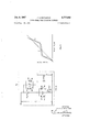
- Fig. 2 is a simplified circuit diagram to aid in the explanation of the operation of the apparatus; while
- Fig. 3 is a graph of an operating characteristic of the tone-adjusting network of Fig. 1.
- the translating system includes a pickup photocell 10 of the conventional electron multiplier type having a primary cathode 10a connected to a source -B and a plurality of multiplier cathodes 1% connected to electrically spaced points on a voltage-divider resistor 11 connected between ground and the unidirectional source B.
- the anode 10c of the cell is connected to a suitable source +B through a load resistor 12, the signal across which is applied by way of a coupling condenser 13 to the input terminals of a photocell amplifier 14, which may be of any suitable wellknown type.
- the output terminals of amplifier 14 are coupled through a coupling condenser 9 to a tone-adjusting net- Work 15 embodying the invention and described in more detail hereinafter.
- the signal output of the tone-adjusting network 15 is applied to a wave-shaping circuit l6, also described hereinafter, for eliminating the distortion of the video-signal carrier wave by the tone-adjusting network.
- the output terminals of the wave-shaping network 16 are connected to an output or load resistor 26 of the voltage-divider type having an adjustable contact 26a.
- the video-signal translating system also includes a eriodic source or screen-frequency generator 20 of any suitable type, but preferably of the electrostatic type described in applicants aforesaid copending application.
- the generator 20 is connected as a variable condenser in the input circuit of a screen amplifier unit 21.
- the rotor 20a of the generator 20 is connected to ground, while the stator 20b is connected to a suitable source of polarizing voltage +3 through an isolating resistor 22.
- the signal output of the screen amplifier 21 is coupled by way of a conductor 23 and a coupling condenser 24 to a voltage divider 25 having an adjustable contact 25a.
- An adjustable portion of the screen-frequency signal applied to the voltage divider 25 is applied by Way of contact a through an isolating resistor 28 and combined with the amplified photocell pickup signal derived from the voltage divider 26 through an isolating resistor 27 and applied to the power amplifier 17.
- the power amplifier 17 is coupled through an output transformer 18 to an engraving tool actuating apparatus 19 which may be of any suitable type, but preferably of the type described in applicants copending application.
- the amplified screen-frequency output from unit 21 is also applied through a coupling condenser 29 to an isolating amplifier 3t) and thence through a coupling condenser 31 and a voltage divider 32 to a power amplifier 33.
- the output signal of the unit 33 is connected to energize a scanning light 34, preferably of the vapor electric type as described in applicants aforesaid copending application.
- the pick-up photocell lo is employed to scan an image to be reproduced.
- the image is illuminated by the scanning light 34, the illumination of which, as explained hereinafter, is modulated at screen frequency.
- the photocell lo thereby develops a pulsating unidirectional signal of screen frequency which is modulated by the variations in intensity of illumination of the elemental areas of the image being scanned.
- This modulated pulsating signal is amplified in the unit 14 and impressed upon the tone-adjusting network 115, wherein its tonal characteristic or gamma is modified, and thence through the unit 16 in which the carrier component of the signal is restored to a sinusoidal wave form.
- the signal output from the unit 16 is mixed with the amplified screen-frequency output from the unit 21 in the resistance network 25, 26, 27, 23 and this combined signal is amplified in the unit 17 for energization of the engraving tool actuating apparatus 19.
- the character of the image plate formed by the unit 19 may be controlled within wide limits, as explained in applicants aforesaid copending application.
- the amplified screen-frequency signal output of the unit 21 is further amplified in the unit 30 and an adjustable portion thereof is selected by adjustment of the voltage divider 32 and applied to the power amplifier 33 wherein it is further amplified and used as a source of energizing potential for the scanner light 34.
- the adjustment of the circuit constants is such that substantially 100% modulation of the light output of the lamp 3 1- is effected, which facilitates the formation of a well defined screen pattern on the plate being engraved.
- the tone-adjusting network 15 included in the above-described video-signal translating system, as mentioned above, this unit is included in the main video-modulated carrier-signal translating channel of the system.
- the tone-adjusting network includes impedance means effectively in series with the video-signal translating channel, a non-linear conductive device connected efiectively in parallel with such impedance means and a non-linear conductive device connected effectively in shunt to the channel, preferably in series with an impedance means which with the device are eflectively in parallel with another impedance means elfectively in shunt to the channel.
- these impedance means comprise a resistor effectively in series with the video-signal translating channel and a resistor 41 and series-connected resistors 42 and 43 effectively in parallel with resistor 41, and both effectively in shunt to the video-signal translating channel.
- the non-linear conductive devices of the network may be in the form of a pair of crystal rectifiers 45, 46 reversely connected in parallel with the resistor 40 and a 4i pair of crystal rectifiers d7, 43 reversely connected in parallel and effectively connected in series with the resistor network comprising the resistors 41, 4-2, 43.
- the tone-adjusting network 1d also includes means for applying conduction-opposing bias potentials of different values to the non-linear conductive devices or rectifiers, whereby the rectifiers 45, 4s become conductive for different amplitudes of the translated videomodulated carrier signal than the rectifiers 4'7, 48, thereby to impart to the network a non-linear amplituderesponse characteristic.
- these bias potentials are applied by means of a resistance voltage-divider network energized from a suitable source +B.
- This voltagedivider network includes a series isolating resistor 4-9 and a T network comprising series arms made up of voltage-divider resistors Sll and 51 and a shunt arm 52.
- the voltage divider 51 is provided with an adjustable contact 51a which is connected to dissimilar electrodes of the rectifiers 45, 46 through a choke 5'4, mid-point voltage-dividing resistors 55 and 56, and a second choke 57.
- the mid-point of resistors 55, S6 is connected to the common terminal of rectifiers 45, 46 through series resistor 40 and the potential drops across resistors 55 and 56 are of such magnitudes and polarities that equal and opposite biasing potentials are applied to rectifiers 45 and 46.
- the common junction of the resistors 40, 55, and 56 is connected by way of a coupling condenser 58 to the common connection of rectifiers 47, 48 as illustrated.
- the bias potential for the rectifiers 47, 48 is derived from the adjustable contact dtla of voltage divider 50 which is connected to a voltage divider comprising resistors 59, i2, and 43.
- the potential at the junction of resistors 42 and 43 is applied through a resistor 44 to the common terminal of rectifiers 4.7 and 4-8 and the potential drops across resistors 42 and are of such magnitudes and polarities that equal and opposite biasing potentials are applied to rectifiers 47 and 4 8.
- the video-signal translating channel also includes the wave-shaping circuit 16 coupled thereto for substantially eliminating wave-form distortion of the carrier signal due to the non-linear translating characteristic of the toneadjusting network 15.
- the signal output of the tone-adjusting network 15 is developed across a load network comprising a coupling condenser so and a load resistor 61 and is applied to the wave-shaping circuit 16 through a second coupling condenser 62 and resistor 63.
- the output signal is applied to the control grid of a vacuum-tube amplifier 64 which may be of the conventional pentode type.
- the tube 64 is provided with a grid leak 65 and a degenerative cathode resistor 66.
- the amplifier 64 is also provided with a degenerative feedback connection comprising a bridged T-filter consisting of low-pass series-resistor arms 67 and 68 and a shunt condenser arm 69, in parallel with a high-pass network consisting of series-condenser arms 7d and 71 and a shunt resistor arm 72.
- the feed-back path is from the anode of the tube 64, through a coupling condenser 73, the filter networks just described, and a voltage-divider resistor 74 to the grid of the tube.
- the operation of the tone-adjusting network 15 may be best explained by reference to the equivalent simplified circuit diagram of Fig. 2, in which equivalent circuit elements are given similar reference numerals.
- the rectifiers 45 and 46 are biased by batteries 75, 76 or" equal potential and opposite polarity.
- rectifiers 47 and 43 are biased by batteries '77 and 78 of equal potential and opposite polarity.
- the potentials of the batteries of 75, 76 considerably exceed those of the batteries 77, 73. it will be understood that the batteries 7543, inclusive, take the place of the voltage-divider network comprising the elements 4%57,
- both pairs of diodes d5, 46 and 47, 48 are maintained non-conductive by their respective applied biasing potentials so that, in etfect, they comprise open circuit switches S1 and S2, respectively, shown in dotted lines in Fig. 2.
- the tone-adjusting network comprises merely the series resistor 40 (R1) and the shunt load resistor 61 (R3). Under these conditions, the attenuation of the tone-adjusting network is such that the input-output characteristic of the network is represented by the portion 1 of the graph of Fig. 3.
- the relationship described continues until the amplitude of the video-modulated carrier signal reaches a value exceeding the bias potential applied to the diodes 47, 48, at which time they become conductivefor the portions of each carrier cycle of an amplitude in excess of the bias potential and for such signal-amplitude portions the diodes 47 and 48 function effectively as a closed switch S2, thereby placing the resistor network 41, 42, 43 (R2) in shunt with the resistor 61 (R3).
- the voltage-divider network comprising these resistors (Rz, R3) and the resistor 40 (R1) is thus modified to apply a reduced portion of the signal input to the signal output terminals and the tone-adjusting network has a repeating ratio represented by the portion 2 of the graph of Fig. 3.
- tone-adjusting network 15 by use of the tone-adjusting network 15, there is provided a controlled tonal characteristic or gamma control by which the low amplitude and high amplitude portions of the video-modulated carrier signal are relatively expanded, while the intermediate amplitude range corresponding to the portion 2 of the graph of Fig. 3 is considerably compressed.
- a controlled tonal characteristic or gamma control by which the low amplitude and high amplitude portions of the video-modulated carrier signal are relatively expanded, while the intermediate amplitude range corresponding to the portion 2 of the graph of Fig. 3 is considerably compressed.
- Such a characteristic would be useful, for example, in a system in which other components were effective to expand the intermediate portion of the amplitude range of the translated video signals.
- the time constants of the low-pass network 67, 68, 69 and the high-pass network 70, 71, 72 are effective to provide Il'lElXlmllm degeneration at the screen frequency with the result that harmonic components comprising the distortion components of the video-modulated carrier applied thereto are substantially attenuated so that the output carrier signal thereof has a substantially sinusoidal wave form.
- a tone-adjusting network comprising: a video-signal translating channel; impedance means efiectively in series with said channel; a first pair of opposed unidirectionally conductive devices connected effectively in parallel with said series impedance means; a second pair of opposed unidirectionally conductive devices connected effectively in shunt to said channel; and means for applying to the devices of said two pairs conduction-opposing biases of different values within the normal range of signal amplitudes, whereby the devices of said two pairs become conductive for different amplitudes of the translated video signal to impart a non-linear amplitude-response characteristic to said network.
- a tone-adjusting network comprising: a video-signal translating channel; impedance means effectively in series with said channel; impedance means effectively in shunt to said channel; two pairs of opposed unidirectionally conductive devices individually connected effectively in parallel with said impedance means; and means for applying to the devices of said two pairs conduction-opposing biases of different values within the normal range of signal amplitudes, whereby the devices of said two pairs become conductive for diiferent amplitudes of the translated video signal to impart a non-linear amplitude-response characteristic to said network.
- a tone-adjusting network comprising: a video-signal translating channel; impedance means effectively in series with said channel; impedance means effectively in shunt to said channel; a first pair of opposed unidirectionally conductive devices connected eifectively in parallel with said series impedance means; a second pair of opposed unidirectionally conductive devices connected efiectively in series with said shunt impedance means; and means for applying to the devices of said two pairs conduction-opposing biases of different values within the normal range of signal amplitudes, whereby the devices of said two pairs become conductive for diiferent amplitudes of the translated video signal to impart a non-linear amplitude-response characteristic to said network.
- a tone-adjusting network comprising: a video-signal translating channel; a resistor effectively in series with said channel; a resistor effectively in shunt to said channel; a first pair of opposed unidirectionally conductive devices connected effectively in parallel with said series resistor; a series connected second pair of opposed unidirectionally con ductive devices and a resistor connected effectively in parallel with said shunt resistor; and means for applying to the devices of said two pairs conduction-opposing biases of different values within the normal range of signal amplitudes, whereby the devices of said two pairs become conductive for different amplitudes of the translated video signal to impart a non-linear amplituderesponse characteristic to said network.
- a tone-adjusting network comprising: a video-signal translating channel; impedance means effectively in series with said channel; a pair of opposed diode rectifiers connected effectively in parallel with said series impedance means; a pair of opposed diode rectifiers connected effectively in shunt with said channel; and means for applying to the rectifiers of said two pairs conduction-opposing biases of difierent values within the normal range of signal amplitudes, whereby said rectifiers become conductive for different amplitudes of the translated video signal to impart a nonlinear amplitude-response characteristic to said network.
- a tone-adjusting network comprising: a video-signal translating channel; a resistor effectively in series with said channel; a second resistor and a load resistor effectively in shunt to said channel; a first pair of opposed unidirectionally conductive devices connected effectively in parallel with said series resistor; a second pair of opposed unidirectionally conductive devices etfectively connected in series with said second resistor; and means for applying to the devices of said two pairs conduction-opposing biases of: diiferent values within the normal range of signal amplitudes, whereby the devices of said two pairs become conductive for different. amplitudes of the translated video signal to impart a non-linear amplitude-response characteristic to said network.
- a tone-adjusting network comprising: a video-modulated carrier-signal translating channel; impedance means effectively in series with said channel; a first pair of opposed unidirectionally conductive devices connected effectively in parallel with said series impedance means; a second pair of opposed unidirectionally conductive devices connected effectively in shunt to said channel; means for applying to the devices of said two pairs conduction-opposing biases of different values within the normal range of signal amplitudes, whereby the devices of said two pairs become conductive for different amplitudes of the translated carrier signal to impart a non-linear amplitude-response characteristic to said network; and a wave-shaping circuit coupled to said channel for substantially eliminating wave-form distortion of said carrier signal due to said non-linear characteristic.
Description
Jan. 8, 1957 'J. A. B-OYAJEAN VIDEO-SIGNAL TONE-ADJUSTING NETWORK 2 Sheets-Sheet 1 Filed Sept. 28, 1951 m ESOQ HAVE 1 1 "ma i Eula: b zwumom 3 8 a rlllllll lullllln RN u Md w 0 B A N H O J My 8 ATTORNEY Jan. 8, 1957 J. A. BOYAJEAN 2,777,058
VIDEO-SIGNAL TONE-ADJUSTING NETWORK Filed Sept. 28, 1951 2 Sheets-Sheet 2 Input Signal l ls s mo FIG.2
INVENTOR.
JOHN A. BOYAJEAN {jg/W40 ATTORNEY United States atent zmmss VIDEO-SIGNAL TUNE-ADJUSTING NETWORK John A. Boyajean, Huntington, N. Y., assignor to Fairchiltl Camera and Instrument Corporation, a corporation of Delaware Application September 28, 1% Serial No. 248,755
7 Claims. (Cl. 259-27) This invention relates to video-signal tone-adjusting networks and, while it is of general application, it is particularly suitable for embodiment in apparatus for producing screened relief pattern plates of the type described in applicants copending application, Serial No. 40,594, filed July 24, 1948, entitled Machine for Producing Screened Relief Pattern Plates, which issued as Patent No. 2,575,546 and subsequent Re. 23,914 and assigned to the same assignee as the present invention, and will be described herein in such an environment.
In the reproduction of visual images by television, photography, printing, etc., it is frequently desirable to introduce at some point in the video-signal translating channel a predetermined amplitude distortion, that is, a non-linear translation of the signal over a certain portion or portions of the signal amplitude range, in order to compensate for non-linear translations in other portions of the system, or in order to modify the overall signal-translating characteristic, or both, to obtain an apparent optimum fidelity of reproduction.
The desirability of such an amplitude distortion is due both to the usual inherent characteristics of the videosignal translating apparatus and the image-reproducing apparatus, as well as to certain well-known physiological phenomena of the observer. Thus, in image-reproducing apparatus of the type described in the aforesaid copending application, certain of the components may have nonlinear translation or response characteristics, among which may be mentioned the reflection characteristics of the paper or the ink, or both; the plate-deforming characteristics of the engraving stylus or its actuating apparatus, or both; and the overprinting of highlight dots and the filling in of the deeper shadow areas due to the fact that the deposition of ink tends to be non-linear when the highlight dots are very small or the shadow deformations are very shallow.
Moreover, in some instances, if the illumination of the incremental areas or" the reproduced image is proportional to the illumination of the corresponding areas of the original image, that is, if the system has a linear overall stimulus-response characteristic, the reproduced images may appear flat or distorted to an observer. in such cases, therefore, it is desirable to give the system a predetermined non-linear overall response characteristic. Such amplitude distortion of a video signal is termed tone compensation or gamma control. The gamma of a system is defined as the slope of the stimulus-response characteristic plotted on a logarithmic scale. When the response is linear, gamma is unity.
It is an object of the present invention, therefore, to provide a new and improved video-signal tone-adjusting network by means of which any desired tone compensation or gamma control of the reproduced image may be procured.
It is another object of the invention to provide a new and improved video-signal tone-adjusting network by means of which the above-described tonal distortions of a video-signal translating system may be readily compensated.
In accordance with the invention, in a video-signal translating system there is provided a tone-adjusting net work comprising a video-signal translating channel, impedance means effectively in series with such channel, a first pair of opposed unidirectionally conductive devices connected effectively in parallel with the series impedance means, and a second pair of opposed unidirectionally conductive devices connected effectively in shunt to the channel. The network also includes means for applying to the conductive devices of the two pairs conductionopposing biases of diiferent values within the normal range of signal amplitudes, whereby the devices of such two pairs become conductive for different amplitudes of the translated video signal to impart a non-linear amplitude-response characteristic to the network.
For a better understanding of the present invention, together with other and further objects thereof, reference is had to the following description taken in connection with the accompanying drawings, While its scope will be pointed out in the appended claims.
Referring now to the drawings, Fig. 1 is a circuit diagram, partly schematic, of a video-signal tone-adjusting network embodied in an apparatus for producing screened relief pattern plates of the type described in applicants aforesaid copending application; Fig. 2 is a simplified circuit diagram to aid in the explanation of the operation of the apparatus; while Fig. 3 is a graph of an operating characteristic of the tone-adjusting network of Fig. 1.
Referring now more particularly to Fig. 1 of the drawings, there is represented an apparatus for producing screened relief pattern plates embodying a video-signal translating system including the tone-adjusting network of the invention. The translating system includes a pickup photocell 10 of the conventional electron multiplier type having a primary cathode 10a connected to a source -B and a plurality of multiplier cathodes 1% connected to electrically spaced points on a voltage-divider resistor 11 connected between ground and the unidirectional source B. The anode 10c of the cell is connected to a suitable source +B through a load resistor 12, the signal across which is applied by way of a coupling condenser 13 to the input terminals of a photocell amplifier 14, which may be of any suitable wellknown type.
The output terminals of amplifier 14 are coupled through a coupling condenser 9 to a tone-adjusting net- Work 15 embodying the invention and described in more detail hereinafter. The signal output of the tone-adjusting network 15 is applied to a wave-shaping circuit l6, also described hereinafter, for eliminating the distortion of the video-signal carrier wave by the tone-adjusting network. The output terminals of the wave-shaping network 16 are connected to an output or load resistor 26 of the voltage-divider type having an adjustable contact 26a.
The video-signal translating system also includes a eriodic source or screen-frequency generator 20 of any suitable type, but preferably of the electrostatic type described in applicants aforesaid copending application. As such, the generator 20 is connected as a variable condenser in the input circuit of a screen amplifier unit 21. Specifically, the rotor 20a of the generator 20 is connected to ground, while the stator 20b is connected to a suitable source of polarizing voltage +3 through an isolating resistor 22. The signal output of the screen amplifier 21 is coupled by way of a conductor 23 and a coupling condenser 24 to a voltage divider 25 having an adjustable contact 25a. An adjustable portion of the screen-frequency signal applied to the voltage divider 25 is applied by Way of contact a through an isolating resistor 28 and combined with the amplified photocell pickup signal derived from the voltage divider 26 through an isolating resistor 27 and applied to the power amplifier 17. The power amplifier 17 is coupled through an output transformer 18 to an engraving tool actuating apparatus 19 which may be of any suitable type, but preferably of the type described in applicants copending application.
The amplified screen-frequency output from unit 21 is also applied through a coupling condenser 29 to an isolating amplifier 3t) and thence through a coupling condenser 31 and a voltage divider 32 to a power amplifier 33. The output signal of the unit 33 is connected to energize a scanning light 34, preferably of the vapor electric type as described in applicants aforesaid copending application.
Considering now the general operation of the videosignal translating system of Fig. 1 and neglecting for the present the tone-adjusting network 15 and the waveshaping network it, the pick-up photocell lo is employed to scan an image to be reproduced. The image is illuminated by the scanning light 34, the illumination of which, as explained hereinafter, is modulated at screen frequency. The photocell lo thereby develops a pulsating unidirectional signal of screen frequency which is modulated by the variations in intensity of illumination of the elemental areas of the image being scanned. This modulated pulsating signal is amplified in the unit 14 and impressed upon the tone-adjusting network 115, wherein its tonal characteristic or gamma is modified, and thence through the unit 16 in which the carrier component of the signal is restored to a sinusoidal wave form. The signal output from the unit 16 is mixed with the amplified screen-frequency output from the unit 21 in the resistance network 25, 26, 27, 23 and this combined signal is amplified in the unit 17 for energization of the engraving tool actuating apparatus 19. By properly adjusting the relative portions of the amplified video signal derived from the voltage divider 26 and of the amplified screen-frequency signal derived from the voltage divider 25, the character of the image plate formed by the unit 19 may be controlled within wide limits, as explained in applicants aforesaid copending application.
The amplified screen-frequency signal output of the unit 21 is further amplified in the unit 30 and an adjustable portion thereof is selected by adjustment of the voltage divider 32 and applied to the power amplifier 33 wherein it is further amplified and used as a source of energizing potential for the scanner light 34. The adjustment of the circuit constants is such that substantially 100% modulation of the light output of the lamp 3 1- is effected, which facilitates the formation of a well defined screen pattern on the plate being engraved.
Referring now more particularly to the tone-adjusting network 15 included in the above-described video-signal translating system, as mentioned above, this unit is included in the main video-modulated carrier-signal translating channel of the system. The tone-adjusting network includes impedance means effectively in series with the video-signal translating channel, a non-linear conductive device connected efiectively in parallel with such impedance means and a non-linear conductive device connected effectively in shunt to the channel, preferably in series with an impedance means which with the device are eflectively in parallel with another impedance means elfectively in shunt to the channel. Specifically, these impedance means comprise a resistor effectively in series with the video-signal translating channel and a resistor 41 and series-connected resistors 42 and 43 effectively in parallel with resistor 41, and both effectively in shunt to the video-signal translating channel. The non-linear conductive devices of the network may be in the form of a pair of crystal rectifiers 45, 46 reversely connected in parallel with the resistor 40 and a 4i pair of crystal rectifiers d7, 43 reversely connected in parallel and effectively connected in series with the resistor network comprising the resistors 41, 4-2, 43.
The tone-adjusting network 1d also includes means for applying conduction-opposing bias potentials of different values to the non-linear conductive devices or rectifiers, whereby the rectifiers 45, 4s become conductive for different amplitudes of the translated videomodulated carrier signal than the rectifiers 4'7, 48, thereby to impart to the network a non-linear amplituderesponse characteristic. Specifically, these bias potentials are applied by means of a resistance voltage-divider network energized from a suitable source +B. This voltagedivider network includes a series isolating resistor 4-9 and a T network comprising series arms made up of voltage-divider resistors Sll and 51 and a shunt arm 52. The voltage divider 51 is provided with an adjustable contact 51a which is connected to dissimilar electrodes of the rectifiers 45, 46 through a choke 5'4, mid-point voltage-dividing resistors 55 and 56, and a second choke 57. The mid-point of resistors 55, S6 is connected to the common terminal of rectifiers 45, 46 through series resistor 40 and the potential drops across resistors 55 and 56 are of such magnitudes and polarities that equal and opposite biasing potentials are applied to rectifiers 45 and 46. The common junction of the resistors 40, 55, and 56 is connected by way of a coupling condenser 58 to the common connection of rectifiers 47, 48 as illustrated. The bias potential for the rectifiers 47, 48 is derived from the adjustable contact dtla of voltage divider 50 which is connected to a voltage divider comprising resistors 59, i2, and 43. The potential at the junction of resistors 42 and 43 is applied through a resistor 44 to the common terminal of rectifiers 4.7 and 4-8 and the potential drops across resistors 42 and are of such magnitudes and polarities that equal and opposite biasing potentials are applied to rectifiers 47 and 4 8.
The video-signal translating channel also includes the wave-shaping circuit 16 coupled thereto for substantially eliminating wave-form distortion of the carrier signal due to the non-linear translating characteristic of the toneadjusting network 15. Specifically, the signal output of the tone-adjusting network 15 is developed across a load network comprising a coupling condenser so and a load resistor 61 and is applied to the wave-shaping circuit 16 through a second coupling condenser 62 and resistor 63. The output signal is applied to the control grid of a vacuum-tube amplifier 64 which may be of the conventional pentode type. The tube 64 is provided with a grid leak 65 and a degenerative cathode resistor 66. The amplifier 64 is also provided with a degenerative feedback connection comprising a bridged T-filter consisting of low-pass series-resistor arms 67 and 68 and a shunt condenser arm 69, in parallel with a high-pass network consisting of series-condenser arms 7d and 71 and a shunt resistor arm 72. The feed-back path is from the anode of the tube 64, through a coupling condenser 73, the filter networks just described, and a voltage-divider resistor 74 to the grid of the tube.
The operation of the tone-adjusting network 15 may be best explained by reference to the equivalent simplified circuit diagram of Fig. 2, in which equivalent circuit elements are given similar reference numerals. In this circuit the rectifiers 45 and 46 are biased by batteries 75, 76 or" equal potential and opposite polarity. Similarly, rectifiers 47 and 43 are biased by batteries '77 and 78 of equal potential and opposite polarity. However, the potentials of the batteries of 75, 76 considerably exceed those of the batteries 77, 73. it will be understood that the batteries 7543, inclusive, take the place of the voltage-divider network comprising the elements 4%57,
inclusive, of Fig. 1.
When the video-modulated carrier signal applied to the terminals 150, 15a of the unit 15 is of a very small amplitude, both pairs of diodes d5, 46 and 47, 48 are maintained non-conductive by their respective applied biasing potentials so that, in etfect, they comprise open circuit switches S1 and S2, respectively, shown in dotted lines in Fig. 2. Under these conditions, the tone-adjusting network comprises merely the series resistor 40 (R1) and the shunt load resistor 61 (R3). Under these conditions, the attenuation of the tone-adjusting network is such that the input-output characteristic of the network is represented by the portion 1 of the graph of Fig. 3.
The relationship described continues until the amplitude of the video-modulated carrier signal reaches a value exceeding the bias potential applied to the diodes 47, 48, at which time they become conductivefor the portions of each carrier cycle of an amplitude in excess of the bias potential and for such signal-amplitude portions the diodes 47 and 48 function effectively as a closed switch S2, thereby placing the resistor network 41, 42, 43 (R2) in shunt with the resistor 61 (R3). The voltage-divider network comprising these resistors (Rz, R3) and the resistor 40 (R1) is thus modified to apply a reduced portion of the signal input to the signal output terminals and the tone-adjusting network has a repeating ratio represented by the portion 2 of the graph of Fig. 3.
Upon still further increase in the amplitude of the video-modulated signal carrier to values exceeding the bias potential applied to the rectifiers 45, 46, these rectifiers become conductive causing them to act effectively as a closed switch S1, thereby short-circuiting the series resistor 4i This results in a repeating ratio of unity, that is, one in which the full signal input is applied to the output of the network, as represented by the portion 3 of the graph of Fig. 3, and this condition obtains for all further increases in amplitude of the video-modulated signal carrier.
Thus it will be seen that, by use of the tone-adjusting network 15, there is provided a controlled tonal characteristic or gamma control by which the low amplitude and high amplitude portions of the video-modulated carrier signal are relatively expanded, while the intermediate amplitude range corresponding to the portion 2 of the graph of Fig. 3 is considerably compressed. Such a characteristic would be useful, for example, in a system in which other components were effective to expand the intermediate portion of the amplitude range of the translated video signals.
it will be obvious to those skilled in the art that additional combinations of parallel and series resistor-diodepair units similar to those s ecifically disclosed may be added to the tone-adjusting network to obtain additional steps or gradations in the attenuation characteristic of r the network.
it can readily be shown that the repeating ratio of the output voltage E2 with respect to the input voltage E1 for each of the conditions described is as follows:
(1) Switches S and S open Repeating ratio=$ (2) Switch if: closed, S open Repeating ratio (3) Switches S1 and S2 both closed Repeating ratiozl Resistor 4t) kilohms 47 Resistor 41 ohms 1500 Resistor 42 do 750 Resistor 43 do 750 Resistor 44 kilohms Resistors S0, 51 do 50 Resistor 52 do 22 Resistors 55, 56 ohms 4700 Condensers 9, 58, 60 microfarad 1 Crystals 45, 46, 47, 48 Type 1N35, 1N54A, or 1N52 The wave-shaping circuit 16 is substantially conventional in construction and operation. Effectively the time constants of the low-pass network 67, 68, 69 and the high- pass network 70, 71, 72 are effective to provide Il'lElXlmllm degeneration at the screen frequency with the result that harmonic components comprising the distortion components of the video-modulated carrier applied thereto are substantially attenuated so that the output carrier signal thereof has a substantially sinusoidal wave form.
While there has been described what is at present considered to be the preferred embodiment of the invention, it will be obvious to those skilled in the art that various changes and modifications may be made therein without departing from the invention, and it is, therefore, aimed in the appended claims to cover all such changes and modifications as fall within the true spirit and scope of the invention.
What is claimed is:
i. In a video-signal translating system, a tone-adjusting network comprising: a video-signal translating channel; impedance means efiectively in series with said channel; a first pair of opposed unidirectionally conductive devices connected effectively in parallel with said series impedance means; a second pair of opposed unidirectionally conductive devices connected effectively in shunt to said channel; and means for applying to the devices of said two pairs conduction-opposing biases of different values within the normal range of signal amplitudes, whereby the devices of said two pairs become conductive for different amplitudes of the translated video signal to impart a non-linear amplitude-response characteristic to said network.
2. In a video-signal translating system, a tone-adjusting network comprising: a video-signal translating channel; impedance means effectively in series with said channel; impedance means effectively in shunt to said channel; two pairs of opposed unidirectionally conductive devices individually connected effectively in parallel with said impedance means; and means for applying to the devices of said two pairs conduction-opposing biases of different values within the normal range of signal amplitudes, whereby the devices of said two pairs become conductive for diiferent amplitudes of the translated video signal to impart a non-linear amplitude-response characteristic to said network.
3. In a video-signal translating system, a tone-adjusting network comprising: a video-signal translating channel; impedance means effectively in series with said channel; impedance means effectively in shunt to said channel; a first pair of opposed unidirectionally conductive devices connected eifectively in parallel with said series impedance means; a second pair of opposed unidirectionally conductive devices connected efiectively in series with said shunt impedance means; and means for applying to the devices of said two pairs conduction-opposing biases of different values within the normal range of signal amplitudes, whereby the devices of said two pairs become conductive for diiferent amplitudes of the translated video signal to impart a non-linear amplitude-response characteristic to said network.
4. In a video-signal translating system, a tone-adjusting network comprising: a video-signal translating channel; a resistor effectively in series with said channel; a resistor effectively in shunt to said channel; a first pair of opposed unidirectionally conductive devices connected effectively in parallel with said series resistor; a series connected second pair of opposed unidirectionally con ductive devices and a resistor connected effectively in parallel with said shunt resistor; and means for applying to the devices of said two pairs conduction-opposing biases of different values within the normal range of signal amplitudes, whereby the devices of said two pairs become conductive for different amplitudes of the translated video signal to impart a non-linear amplituderesponse characteristic to said network.
5. In a video-signal translating system, a tone-adjusting network comprising: a video-signal translating channel; impedance means effectively in series with said channel; a pair of opposed diode rectifiers connected effectively in parallel with said series impedance means; a pair of opposed diode rectifiers connected effectively in shunt with said channel; and means for applying to the rectifiers of said two pairs conduction-opposing biases of difierent values within the normal range of signal amplitudes, whereby said rectifiers become conductive for different amplitudes of the translated video signal to impart a nonlinear amplitude-response characteristic to said network.
6. In a video-signal translating system, a tone-adjusting network comprising: a video-signal translating channel; a resistor effectively in series with said channel; a second resistor and a load resistor effectively in shunt to said channel; a first pair of opposed unidirectionally conductive devices connected effectively in parallel with said series resistor; a second pair of opposed unidirectionally conductive devices etfectively connected in series with said second resistor; and means for applying to the devices of said two pairs conduction-opposing biases of: diiferent values within the normal range of signal amplitudes, whereby the devices of said two pairs become conductive for different. amplitudes of the translated video signal to impart a non-linear amplitude-response characteristic to said network.
7. In a video-signal translating system, a tone-adjusting network comprising: a video-modulated carrier-signal translating channel; impedance means effectively in series with said channel; a first pair of opposed unidirectionally conductive devices connected effectively in parallel with said series impedance means; a second pair of opposed unidirectionally conductive devices connected effectively in shunt to said channel; means for applying to the devices of said two pairs conduction-opposing biases of different values within the normal range of signal amplitudes, whereby the devices of said two pairs become conductive for different amplitudes of the translated carrier signal to impart a non-linear amplitude-response characteristic to said network; and a wave-shaping circuit coupled to said channel for substantially eliminating wave-form distortion of said carrier signal due to said non-linear characteristic.
References Cited in the file of this patent UNITED STATES PATENTS 2,021,920 Norwine Nov. 26, 1935 2,098,370 Bartels Nov. 9, 1937 2,212,832 Holzler Aug. 27, 1940 2,342,238 Barney Feb. 22, 1944 2,453,958 Andresen Nov. 16, 1948 2,552,348 Shapiro et al May 8, 1951 2,600,423 Nolle June 17, 1952 2,641,649 Pierce June 9, 1953 FOREIGN PATENTS 418,811 Great Britain Oct. 31, 1934 475,446 Great Britain Nov. 19, 1937
Priority Applications (1)
| Application Number | Priority Date | Filing Date | Title |
|---|---|---|---|
| US248755A US2777058A (en) | 1951-09-28 | 1951-09-28 | Video-signal tone-adjusting network |
Applications Claiming Priority (1)
| Application Number | Priority Date | Filing Date | Title |
|---|---|---|---|
| US248755A US2777058A (en) | 1951-09-28 | 1951-09-28 | Video-signal tone-adjusting network |
Publications (1)
| Publication Number | Publication Date |
|---|---|
| US2777058A true US2777058A (en) | 1957-01-08 |
Family
ID=22940536
Family Applications (1)
| Application Number | Title | Priority Date | Filing Date |
|---|---|---|---|
| US248755A Expired - Lifetime US2777058A (en) | 1951-09-28 | 1951-09-28 | Video-signal tone-adjusting network |
Country Status (1)
| Country | Link |
|---|---|
| US (1) | US2777058A (en) |
Cited By (13)
| Publication number | Priority date | Publication date | Assignee | Title |
|---|---|---|---|---|
| US2962548A (en) * | 1957-08-14 | 1960-11-29 | Rudolf Hell Kommanditgesellsch | Device for increasing contrasts at tone value leaps and contours in printing forms |
| DE1138424B (en) * | 1959-08-04 | 1962-10-25 | Philips Patentverwaltung | Circuit arrangement for correcting the gradation of a video signal |
| US3482039A (en) * | 1965-05-13 | 1969-12-02 | Zeuthen & Aagaard As | Method and apparatus for producing a laminar printing form |
| US3769455A (en) * | 1972-03-01 | 1973-10-30 | Werkspoor Amsterdam Nv | Method and apparatus for making half-tone screen printing cylinders |
| US5424845A (en) * | 1993-02-25 | 1995-06-13 | Ohio Electronic Engravers, Inc. | Apparatus and method for engraving a gravure printing cylinder |
| US5438422A (en) * | 1993-02-25 | 1995-08-01 | Ohio Electronic Engravers, Inc. | Error detection apparatus and method for use with engravers |
| US5440398A (en) * | 1993-02-25 | 1995-08-08 | Ohio Electronic Engravers, Inc. | Error detection apparatus and method for use with engravers |
| US5617217A (en) * | 1993-02-25 | 1997-04-01 | Ohio Electronic Engravers, Inc. | Engraving method and apparatus for generating engraving drive signals for engraving engraved areas of accurately controlled size in the surface of a workpiece using coefficient values and associated set up parameter values |
| US5671063A (en) * | 1993-02-25 | 1997-09-23 | Ohio Electronic Engravers, Inc. | Error tolerant method and system for measuring features of engraved areas |
| US5737090A (en) * | 1993-02-25 | 1998-04-07 | Ohio Electronic Engravers, Inc. | System and method for focusing, imaging and measuring areas on a workpiece engraved by an engraver |
| US5825503A (en) * | 1993-02-25 | 1998-10-20 | Ohio Electronic Engravers, Inc. | Engraving apparatus and method for adjusting a worn stylus using a midtone correction |
| US5831746A (en) * | 1993-02-25 | 1998-11-03 | Ohio Electronic Engravers, Inc. | Engraved area volume measurement system and method using pixel data |
| US6362899B1 (en) | 1993-02-25 | 2002-03-26 | Mdc Max Daetwyler Ag | Error detection apparatus and method for use with engravers |
Citations (10)
| Publication number | Priority date | Publication date | Assignee | Title |
|---|---|---|---|---|
| GB418811A (en) * | 1933-06-27 | 1934-10-31 | Gerard De Monge | Improvements relating to means for eliminating parasitical oscillations in radio-electric reception |
| US2021920A (en) * | 1935-01-15 | 1935-11-26 | Bell Telephone Labor Inc | Control circuits |
| US2098370A (en) * | 1934-11-05 | 1937-11-09 | Telefunken Gmbh | Automatic control of amplification |
| GB475446A (en) * | 1935-09-30 | 1937-11-19 | Telefunken Gmbh | Improvements in or relating to electric impedance networks |
| US2212832A (en) * | 1936-08-07 | 1940-08-27 | Siemens Ag | Four pole device with nonlinear resistors |
| US2342238A (en) * | 1941-12-31 | 1944-02-22 | Bell Telephone Labor Inc | Variable attenuation circuits |
| US2453958A (en) * | 1946-07-20 | 1948-11-16 | Gilbert J C Andresen | Signal amplitude limiting system |
| US2552348A (en) * | 1946-06-11 | 1951-05-08 | Jefferson Standard Broadcastin | Wave shaper for radio signaling |
| US2600423A (en) * | 1948-04-30 | 1952-06-17 | Electrodyne Co | Electrical system with output signal varying logarithmically with respect to the input signal |
| US2641649A (en) * | 1951-06-26 | 1953-06-09 | Rca Corp | Wave shaping circuit |
-
1951
- 1951-09-28 US US248755A patent/US2777058A/en not_active Expired - Lifetime
Patent Citations (10)
| Publication number | Priority date | Publication date | Assignee | Title |
|---|---|---|---|---|
| GB418811A (en) * | 1933-06-27 | 1934-10-31 | Gerard De Monge | Improvements relating to means for eliminating parasitical oscillations in radio-electric reception |
| US2098370A (en) * | 1934-11-05 | 1937-11-09 | Telefunken Gmbh | Automatic control of amplification |
| US2021920A (en) * | 1935-01-15 | 1935-11-26 | Bell Telephone Labor Inc | Control circuits |
| GB475446A (en) * | 1935-09-30 | 1937-11-19 | Telefunken Gmbh | Improvements in or relating to electric impedance networks |
| US2212832A (en) * | 1936-08-07 | 1940-08-27 | Siemens Ag | Four pole device with nonlinear resistors |
| US2342238A (en) * | 1941-12-31 | 1944-02-22 | Bell Telephone Labor Inc | Variable attenuation circuits |
| US2552348A (en) * | 1946-06-11 | 1951-05-08 | Jefferson Standard Broadcastin | Wave shaper for radio signaling |
| US2453958A (en) * | 1946-07-20 | 1948-11-16 | Gilbert J C Andresen | Signal amplitude limiting system |
| US2600423A (en) * | 1948-04-30 | 1952-06-17 | Electrodyne Co | Electrical system with output signal varying logarithmically with respect to the input signal |
| US2641649A (en) * | 1951-06-26 | 1953-06-09 | Rca Corp | Wave shaping circuit |
Cited By (19)
| Publication number | Priority date | Publication date | Assignee | Title |
|---|---|---|---|---|
| US2962548A (en) * | 1957-08-14 | 1960-11-29 | Rudolf Hell Kommanditgesellsch | Device for increasing contrasts at tone value leaps and contours in printing forms |
| DE1138424B (en) * | 1959-08-04 | 1962-10-25 | Philips Patentverwaltung | Circuit arrangement for correcting the gradation of a video signal |
| US3482039A (en) * | 1965-05-13 | 1969-12-02 | Zeuthen & Aagaard As | Method and apparatus for producing a laminar printing form |
| US3769455A (en) * | 1972-03-01 | 1973-10-30 | Werkspoor Amsterdam Nv | Method and apparatus for making half-tone screen printing cylinders |
| US5424845A (en) * | 1993-02-25 | 1995-06-13 | Ohio Electronic Engravers, Inc. | Apparatus and method for engraving a gravure printing cylinder |
| US5438422A (en) * | 1993-02-25 | 1995-08-01 | Ohio Electronic Engravers, Inc. | Error detection apparatus and method for use with engravers |
| US5440398A (en) * | 1993-02-25 | 1995-08-08 | Ohio Electronic Engravers, Inc. | Error detection apparatus and method for use with engravers |
| US5617217A (en) * | 1993-02-25 | 1997-04-01 | Ohio Electronic Engravers, Inc. | Engraving method and apparatus for generating engraving drive signals for engraving engraved areas of accurately controlled size in the surface of a workpiece using coefficient values and associated set up parameter values |
| US5621533A (en) * | 1993-02-25 | 1997-04-15 | Ohio Electronic Engravers, Inc. | Method for automatically controlling an engraver in response to a plurality of engraving setup parameters which may be input in real units |
| US5671063A (en) * | 1993-02-25 | 1997-09-23 | Ohio Electronic Engravers, Inc. | Error tolerant method and system for measuring features of engraved areas |
| US5737091A (en) * | 1993-02-25 | 1998-04-07 | Ohio Electronics Engravers, Inc. | Error detection apparatus and method for use with engravers |
| US5737090A (en) * | 1993-02-25 | 1998-04-07 | Ohio Electronic Engravers, Inc. | System and method for focusing, imaging and measuring areas on a workpiece engraved by an engraver |
| US5808749A (en) * | 1993-02-25 | 1998-09-15 | Ohio Electronic Engravers, Inc. | Engraving system and engraving signal generator for engraving workpieces |
| US5808748A (en) * | 1993-02-25 | 1998-09-15 | Ohio Electronic Engravers, Inc. | Method and system for generalizing an engraving drive signal in response to an engraving system |
| US5825503A (en) * | 1993-02-25 | 1998-10-20 | Ohio Electronic Engravers, Inc. | Engraving apparatus and method for adjusting a worn stylus using a midtone correction |
| US5831746A (en) * | 1993-02-25 | 1998-11-03 | Ohio Electronic Engravers, Inc. | Engraved area volume measurement system and method using pixel data |
| US6362899B1 (en) | 1993-02-25 | 2002-03-26 | Mdc Max Daetwyler Ag | Error detection apparatus and method for use with engravers |
| US6515772B1 (en) | 1993-02-25 | 2003-02-04 | Mdc Max Daetwyler Ag | Apparatus and method for engraving a gravure printing cylinder |
| US6614558B1 (en) | 1993-02-25 | 2003-09-02 | Mdc Max Daetwyler Ag | Engraver and method for focusing and measuring areas on a workpiece engraved by the engraver |
Similar Documents
| Publication | Publication Date | Title |
|---|---|---|
| US2777058A (en) | Video-signal tone-adjusting network | |
| US2692333A (en) | Wave shaping circuit | |
| US3441663A (en) | Non-linear amplifiers and systems | |
| US2552588A (en) | Gamma control circuit | |
| US2363813A (en) | Electrical control circuit | |
| US2873312A (en) | Modulator with photoelectric signal source and compressor for facsimile | |
| US2304057A (en) | Keystone correction circuit | |
| US2730567A (en) | Facsimile scanning method and apparatus for predetermined signal output and contrast | |
| US2047533A (en) | Television method | |
| US2378999A (en) | Compensation amplifier system | |
| US3488434A (en) | Control system for photosensitive video recorder | |
| US3100815A (en) | Apparatus for producing color separation negatives and the like | |
| US2331770A (en) | Electrical compensation for tone distortion in electromechanical engraving | |
| US2096985A (en) | Television | |
| US3629493A (en) | Screening process simulation apparatus | |
| US2247512A (en) | Television video-frequency signaltranslating system | |
| US2262156A (en) | Method and means for electrically compensating for photographic distortion | |
| US2450445A (en) | Modulation | |
| US3005045A (en) | Video quantizing and contour level apparatus | |
| US2541060A (en) | Tone and density compensating device | |
| US2564554A (en) | Background control and synchronizing signal separating circuit | |
| US2208927A (en) | Electro-optical image production | |
| US2169714A (en) | Black spot correcting means | |
| US2854635A (en) | Video modulator | |
| US2469606A (en) | Video signal level control |