US2777095A - Lightning arrester - Google Patents
Lightning arrester Download PDFInfo
- Publication number
- US2777095A US2777095A US383311A US38331153A US2777095A US 2777095 A US2777095 A US 2777095A US 383311 A US383311 A US 383311A US 38331153 A US38331153 A US 38331153A US 2777095 A US2777095 A US 2777095A
- Authority
- US
- United States
- Prior art keywords
- arrester
- electrode
- valve
- current
- housing
- Prior art date
- Legal status (The legal status is an assumption and is not a legal conclusion. Google has not performed a legal analysis and makes no representation as to the accuracy of the status listed.)
- Expired - Lifetime
Links
Images

Classifications
-
- H—ELECTRICITY
- H01—ELECTRIC ELEMENTS
- H01T—SPARK GAPS; OVERVOLTAGE ARRESTERS USING SPARK GAPS; SPARKING PLUGS; CORONA DEVICES; GENERATING IONS TO BE INTRODUCED INTO NON-ENCLOSED GASES
- H01T1/00—Details of spark gaps
- H01T1/14—Means structurally associated with spark gap for protecting it against overload or for disconnecting it in case of failure
Landscapes
- Emergency Protection Circuit Devices (AREA)
Description
1957- H. o. STOELTING LIGHTNING ARRESTEP.
2 Sheets-Sheet 1 Filed Sept. 50, 1953 FIG.I.
INVENTOR.
BY f d? 7 G W U W T S 0 N A M R E H A TTORNE Y Jan. 8, 1957.
H. O. STOELTING LIGHTNING ARRESTER 2 Sheets-Sheet 2 Filed Sept. 30, 1953 FIG.2.
FIG.3.
FIG.4.
HERMAN O. STOELTING INVENTOR.
ATTORNEY United States Patent LIGHTNING ARRESTER Herman O. Stoelting, Milwaukee, Wis, assignor' to McGraw Electric Company, Milwaukee, Wis, a corporation of Delaware- Applicafion September 30, 1953, Serial No. 383,311
Claims. (Cl. 31766) The present invention relates to excess-voltage protective devices, and particularly, but not necessarily, to thosewhich are utilized for the protection of long transmission lines, or other lines or apparatus which are subject to excess-voltage surges of long duration.
One commonly used form of excess-voltage protective devices has been the valve-type lightning arrester, which is capable of passing heavy discharge-current when im pressed with voltages in excess of the rated voltage of theprotective device, and which is capable of substantially interrupting said discharge upon the return of rated voltage-conditions. The valve-type element is normally positioned intermediate the line-to-ground terminals, and is normally out of circuit being separated from the terminals by means of one or more sets of spark gaps. This material preferably comprises certain proportions of silicon carbide, sodium silicate and silicon dioxide.
On flow of surge current, due either to a lightning stroke or to a switching disturbance, a conducting path is momentarily established through the arrester which, in the ideal'arrester, should be disrupted on termination of flow. of surge current. In this manner the arrester simulates the action of a valve which is openedon occurrence of an abnormal voltage on the system to permit the flow ofsurge current to ground, but which is automatically closed assoon as the excess voltage is dissipated.
It is the general practice to provide valve-type'lightning arresters that are hermetically sealed from the atmosphere. Ordinarily the valve element does not generate appreciable amounts of gas, nor is there any detectable chemical change in the valve element during the discharge of the surge current as long as the lightning arrester is ingood operating condition. However, when a lightning arresterfails, much of the: valve material is caused to fuse, and the material is formed into a conducting pathof comparatively low resistance to flow of power current. After the flow of surge current has ceased, the resistance of the failed arrester is not restored to it's normal or substantially infinite resistance to flow of current at power frequency, and a discharge or flow of. power current takes place through it. The fusion of valvematerialparticles causes a chemical change in the valve element with an accompanying sudden release of copious amounts of gaseous products. Because of the rigid seals on the arrester, the sudden rise of pressure may be high enough to cause the housing of the arrester to explode.
An explosion of a high voltage line-type arrester is generally much more severe than the explosion of the smaller distribution-type arresters, since the housing and the seals of the line-type arresters are generally much stronger than the distribution-type arresters. Flying porcelain from the exploded arrester may endanger personnel and other nearby equipment.
It is therefore an object of the present invention to provide a pressure relief vent means for valve-type lightning arresters' that is arranged to permit any gaseous ice 2, products from certain. chemical changes occurring on failure of a lightning-arrester to be vented from the arrester to' prevent explosion from an accumulation of, the products.
It is another object of. the present invention to provide a pressure relief vent means operatively associated with an electrical disconnect means for a valve-type-lightning arrester for relieving any pressures created on production ofgaseous products during chemical changes occurring under a'failure of said lightning arrester.
It is, a further object of the present invention to provide apressure relief vent means for a valve-type lightning arrester, which in its preferred form is of an explosive cartridgertype circuit interrupting means that is in series gap relationship, with. the characteristic valve material of the arrester, and whichis. adapted to be exploded on heating above a predetermined temperature caused by excessive current. conditions due to failure of said valve material, and which will permit any gaseous products occurring on failure. to he released to atmosphere.
Foramore complete understanding of the nature and scope of the present invention reference may be had to the following detailed. description, taken in connection with the accompanying drawings, in which:
Fig. 1 is an elevational view, partly in section, of a valve-type. lightning arrester embodying the novel pres- SUIGJI'CllCf'. venting means operating in conjunction with one terminal electrode of the arrester.
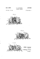
Fig. 2 is an enlarged fragmentary sectional view of the lower portion-of the valve-type arrester illustrated in Fig. 1.
Fig. 3 is a fragmentary sectional view of another embodiment of the venting'means.
Fig. 4:is' a fragmentary sectional view of a further embodiment of the venting means.
The lightning arrester, generally denoted by the reference. character A,. is of the conventional valve type, and is preferably installed for the protection of transmission and distribution equipment. The valve-type arrester comprises a tubularinsulating' housing 1 having a plurality of spaced skirts or petticoats 2 intermediate its ends. The petticoats' act as a means for extending the sparkover distance between terminals and provide a series of water sheds and dry areas in wet weather. 7 The insulating housing l" is preferably of porcelain coated with a uniform glaze, which facilitates self-cleaning when the arrester is exposed to dirtyatmospheres.
The bore of thetuhular housing is packed'with the conventional characteristic valve element 3, which-may be provided under the teachings of the Stoelting Patent No. 2,305,577, issued December 15, 1942. The valve-element generally comprises various proportions of a mixture of silicon carbide, sodium silicate and silicon dioxide. Each end of the valve element is preferably coatedwith a' metallic coating 4' to provide good electrical contact with the spark gap. The spark gap assembly is composed of a series of heavy, alloy disks 5 having high arc resistance. The disks are separated by ceramic spacers (not shown) preferably withsilvered faces, and are mounted on and held'i'n alignment by a steatite rod 7; The spark gap assembly is preferably divided into two short sections, one of which is located at each end of the housing. This construction gives great mechanical strength and the ability to withstand the shocks of shipping and handling. It is to be noted that like reference characters have been used for like parts in this figure and also throughout the various other drawings.
The upper gap structure is held in position by constant pressure from a coil spring 8 between the gap assembly and the electrode sealing cap 9. Conducting, radially spaced straps 10- are provided to shunt the spring and provide positive electrical contact between the sealing cap and the gap assembly.
An hermetic seal at each end of the arrester is preferably made by compressing and retaining an insulating gasket between the sealing cap and the flanged end portion of the housing 1. The upper end cap 16 is preferably of cast malleable iron, and is cemented securely to the housing to provide the means for mounting and making electrical connections. Electrical connection is made at the terminal lugs 13 with conventional terminal clamps (not shown).
The lower end cap 20 is substantially identical to the opposite cap 16, but is provided with radially spaced vent openings 21, as shown in Figs. 2, '3, and 4 for purposes hereinafter described. Terminal connections to the lower cap 20 are made at the terminal lugs 22.
The preferred embodiment of the present invention will be described with particular attention to Fig. 2, wherein the lower electrode sealing cap 23 is provided with a centrally located support 24 having an opening 25 arranged to freely and slidably receive a plug electrode 26 having a flanged portion 27 engaging a gasket member 28 interposed between the flange 27 and the support 24. The protruding end of the electrode 26 preferably is threaded and engages the lower threaded end of a frangible tubular insulating member 29. The member 29 may be made of Bakelite or other insulating material adapted to rupture under certain pressure conditions exerted within its bore, as will be hereinafter described. The extremity of the electrode 26 is recessed and bored to provide a hollow portion 345 in which an explosive cap 31 is disposed. The upper portion of the frangible member 29 is threadingly engaged with a conducting electrode member 32 provided with a circumferential lip portion 33 surrounding, and spaced from, the portion of the electrode 26. The upper portion of the electrode member 32 is provided with a peripheral flange 34 to receive the lower end of the coil spring 8.
A resistor 35 is provided to divert a few milliamperes of charging current which normally flows through the gaps of the high voltage arrester. The resistor is electrically connected to both the electrode 32 and electrode sealing cap 23. Without this resistor the isolating gap would be continually sparking-over and causing objectionable radio interference. The resistance is maintained sufficiently high in order that in the event of an excess voltage surge a sparkover will occur between the lip 33 and the portion 30 of the electrode 26 to divert the surge current from the resistor under normal action during an over-voltage condition.
Operation of the novel pressure is as follows:
If an excessively high current passes through the arrester valve material, it may cause a breakdown of this material and cause the granular particles to fuse, and also bring about other collateral chemical changes. These chemical changes under the influence of continuous current fiow provide reactions that often evolve copious amounts of gaseous products that accumulate to create relatively high pressure conditions within the arrester housing. The products probably include, in various amounts, water vapor, carbon dioxide and carbon monoxide. These products are not dangerous in themselves, but do create forces within the hermetically sealed structure that will cause it to explode and endanger personnel and nearby equipment. it has also been found that gaseous products are evolved when valve elements, such as silicon carbide, include other binders than sodium silicate. These products may be evolved at relatively high pressures during failure of all types of valve arresters, including those using conventional ceramic binders.
There is a definite time lag period during which the pressures are built up, and if properly vented, this pressure may be discharged to the atmosphere before it may release venting means reach the danger point. In the past, there have been attempts to provide venting by means of rupturable diaphragms and inherent weak structural sections in the housing. However, it will be apparent that such devices only operate after considerable time delay, and the pressures built up during this delay might be of suflicient force to cause damage on rupture of the diaphragms or the housing.
The main advantage of the present devices lies in the fact that the relief vent means is actuated by the excessive follow current which flows through the arrester, and not by the pressures that might be created. Thus, it is possible to vent the arrester before any of the high pressures are developed. That is, under normal operation, assuming that a surge to which the arrester is subjected is not of such magnitude as to destroy the valve characteristics of the valve element 3, then as soon as the line voltage returns to normal, the valve element will reduce the flow of current therethrough to a valve which will enable the gap to break the arc and thereby interrupt current flow through the arrester. However, occasionally surges occur on power lines which are of such magnitude as to either destroy the arrester or change the valve characteristics of the material. When the coordinated characteristics of the gap assembly and the valve material have been altered by excessive energy discharges, the arrester may no longer be effective to interrupt current flow therethrough.
When the arrester is subjected to these damaging or destructive surges or current flow, current passing between the electrode lip 33 and the conducting portion 30 of the electrode 26 will raise the temperature of the portion 30, and the heat thus generated will be conducted to the explosive cap 31. Current flowing over a predetermined period of time will cause the temperature of the cap 31 to be raised sufficiently to explode the material in the cap and the expanding gases will drive the cap out of the portion 30 and rupture the frangible member 29. Upon rupture, the electrode plug 26 will be displaced to break the hermetic seal and provide a vent within the bore of the tubular housing 1 through the support 24 of the sealing cap 23. Thus, any gases created during this excessive current flow will be vented through the opening 25 of the cap 23 and out the vents 21 of the base portion 20, where they will be discharged to the atmosphere.
Another embodiment of the present invention is disclosed in Fig. 3, wherein the novel pressure release venting means takes the form of a current responsive low melting alloy joint. In the embodiment of Fig. 3, the housing of one of the arresters is again hermetically sealed by means of the electrode sealing cap 23 and the gasket 15 mounted in a lower end cap 20. The end cap 20 is again provided with radially spaced vent openings 21. This cap 23 is formed with an integral support 24 having a centrally located opening 25.
The opening 25 is normally hermetically sealed by means of a resilient gasket member 40 interposed between the support 24 of the electrode sealing cap 23 and the headed portion 41 of the plug electrode 42 seated in the opening. The plug electrode 42 has a portion extending within the opening and normally engaging an intermediate electrode 43. The plug electrode 42 and the intermediate electrode 43 are joined by means of a low melting alloy joint 44, and are biased towards separation by means of a coil spring 45. A tubular insulating housing 46, which may be of Bakelite, is positioned to rest on the support 24 of the cap 23 and is threaded at its upper end to receive an upper electrode 47 making contact with the straps 10 and the spring 8. Vent ports 48 are provided in the wall of the housing 46.
It is again advisable to provide a resistor 49 between the electrode members 47 and 43 in order to dissipate the few milliamperes of current which are normally discharging in the arrester, and would otherwise interfere with radio reception.
The embodiment of Fig. 3 operates in substantially the same manner as described in connection with the embodiment of Figs. 1 and 2. That is, under normal operation, assuming that a surge to which the arrester is subjected, is not of such magnitude as to destroy the valve characteristics of the valve element, then as soon as the line voltage returns to normal, the valve element will reduce, the flow of current therethrough to a value which will enable the gap to break the arc and thereby interrupt current flow through the arrester. However, on surges that might be of such magnitude, or of such current value, that would either destroy the arrester or change the valve characteristics of the material, the arrester may no longer be efiective to interrupt current flow therethrough.
The destructive current flow passing failed arrester to the upper electrode 47, the resistor 49, the intermediate electrode 43; the alloy joint 44 and to the plug electrode 42, will raise a temperature of the joint 44 to cause it to melt. Inasmuch as the. plug electrode, 42 is biased towards separation from the intermediate electrode 43 by the coil spring 45, the plug electrode 42 will be displaced from the position shown in Fig. 3 to break the hermetic seal and expose the bore of the housing 1 to the atmosphere through the opening 25 and the vent openings 21. Any gases that might be created by chemical changes in the valve element subsequent to excessive current flow, will be vented through the ports 48 to be discharged to atmosphere.
Still another embodiment of the present invention will be described with particular reference to Fig. 4, wherein a fragmentary sectional view discloses the lower end portion of the arrester. The present embodiment utilizes a tempered glass which is critically responsive to heat, and which will shatter or disintegrate into many pieces losing its compressive strength. More particularly, the plug electrode 59 is inserted in the opening 25 of the support 24 of the electrode sealing cap 23, and threadingly engages the lower portion of the insulating glass member 51. The glass member rests on a resilient gasket 52, which also acts to provide a'hermetic seal for the interior of the housing 1-. An upper electrode member 53 threadingly engages the upper portion of the glass member 51 and makes electrical contact with the plug electrode 56 through a resistor 54 interposed therebetween. A cushioning gasket 55 is positioned between the upper elec trode 53 and the glass member 51. i
The operation of the embodiment of Fig. 4 is substantially identical to the operation of the previously described embodiments. That is, on fiow of current in excess of predetermined value, the temperature of the electrodes 50 and 53 will be caused to increase, and this continual rise will cause the high tempered glass to shatter. The lower plug electrode 5t} will then be displaced to provide a vent through the opening 25 and the electrode sealing cap 23. Thus, any gases created during flow of this excess current through the valve material, will be caused to be discharged to atmosphere through the vent openings 21 in the end cap 20.
Highly tempered glasses of the nature described are well known in the glass industry, and can be tempered in such fashion as to shatter when heated under certain conditions. The resistor 54 is again inserted to divert the few milliamperes of charging current normally flowing through the gap, and which might otherwise be the cause of objectionable radio interference.
It is to be noted that although each embodiment of the novel pressure relief vent means is disclosed as being associated with one particular sealing cap, it is within the scope of the present invention to provide such means for either end of the arrester, or at both ends if preferred (not shown).
Although the pressure relief vent means has been described to operate in combination with valve-type arresters having spark gap assemblies preferably positioned at both ends of the-arrester, it will be apparent that the device may be readily applied to arrester constructions where the gap assembly is located at a single end. The device is also applicable to arresters having the gap elements disposed between axially spaced valve element portions (not shown). The arrester housing of such structures would naturally have to be vented to permit the gases to escape to atmosphere.
Arresters have been known to fail due to increased pressure interiorly of the housing caused by the force of the are alone traveling in a tightly constricted space, usually between the element and the insulating housing. This pressure naturally needs to be vented for safe operation of the arrester. The present pressure relief venting means, as described, will permit an immediate release of such pressure responsive to the excessive current flow substantially simultaneous with the Striking of the are.
It will be apparent that there has been provided by the present invention a novel pressure relief vent means in combination with a conventional valve type lightning arrester that will provide an immediate discharge of gases occurring with the housing of a failed lightning arrester simultaneously with the occurrence of that failure, in order to prevent an accumulation of gases that would otherwise cause a damaging explosion with consequent destruction to personnel and nearby equipment.
I claim:
1. In a lightning arrester comprising a tubular insulating housing having a bore, valve material contained within said bore and being capable of evolving gaseous products under pressure during predetermined current conditions, at least one set of gap electrodes, and a pair of spaced-apart terminal caps, at least one of said caps defining an opening therein, the combination with an hermetic seal for said housing bore, a pressure relief vent means operatively associated with said one of said terminal caps and comprising a plug-like member seated against the outside of said opening in sealing relation with said one cap, and having a portion extending inwardly through said opening, means within said housing exerting tension on said inwardly extending portion to maintain a sealing relation between said plug-like member and said opening, a fast-acting thermal responsive actuator independent of said releasable electrode and instantly responsive to current due to subnormal resistance of said valve material to suddenly release the tension on said inwardly extending portion to effect removal of said plug-like member from its sealing engagement'with said one terminal, whereby said gaseous products may be discharged to the atmosphere.
2. In a lightning arrester comprising a tubular insulating housing having a bore, valve material contained within said bore and being capable of evolving gaseous products under pressure during predetermined current conditions, at least one set of gap electrodes, and a pair of spaced apart terminal caps, at least one of said caps defining an opening therein, the combination with an hermetic seal for said housing bore, a pressure relief vent means operatively associated with said one of said terminal caps and comprising a plug-like releasable electrode member normally seated in said opening in releasable sealing engagement with said one terminal cap to complete said hermetic seal and having a portion extending inwardly through said opening, means within said housing exerting tension on said inwardly extending portion to maintain the sealing relation between said plug-like member and said opening, a stationary electrode in electrical connection with said gap electrodes, said electrodes being in insulating relationship to provide a gap, a resistor in shunt relationship with said gap, and a thermal responsive actuator independent of said releasable electrode and responsive to current due to subnormal resistance of said valve material including an explosive cap operatively associated with said last-men tioned electrode to elfect release of the tension on said 7. inwardly extending member responsive to said predetermined current conditions, Whereby said gaseous products may be discharged to atmosphere.
3. In a lighting arrester comprising a tubular insulating housing having a bore, valve material contained Within said bore and being capable of evolving gaseous products under pressure during predetermined current conditions, at least one set of gap electrodes, and a pair of spaced apart terminal caps, at least one of said caps defining an opening therein, the combination with an hermetic seal for said housing bore, a pressure relief vent means operatively associated with said one of said terminal caps and comprising a plug-like releasable electrode member normally seated in said opening in releasable sealing engagement with said one terminal cap to complete said hermetic seal and having a portion extending inwardly through said opening, means Within said housing exerting tension on said inwardly extending portion to maintain the sealing relation between said plug-like member and said opening, a stationary electrode in electrical connection with said gap electrodes, said electrodes being in insulating relationship to provide a gap, a resistor in shunt relationship with said gap, and a thermal responsive actuator independent of said releasable electrode and responsive to current due to subnormal resistance of said valve material including a friable member operatively associated with said last-mentioned electrode to efiect release of the tension on said inwardly extending member responsive to said current conditions, whereby said gaseous products may be discharged to atmosphere.
4. in a lightning arrester comprising a tubular insulating housing having a bore, valve material contained within said bore and being capable of evolving gaseous products under pressure during predetermined current conditions, at least one set of gap electrodes, and a pair of spaced apart terminal caps, at least one of said caps defining an opening therein, the combination with an hermetic seal for said housing bore, a pressure relief vent means operatively associated With said one of said terminal caps and comprising a plug-like releasable electrode member normally seated in said opening in releasable sealing engagement with said one terminal cap to complete said hermetic seal and having a portion extending Q an inwardly through said opening, means within said housing exerting tension on said inwardly extending portion to maintain the sealing relation between said plug-like member and said opening, a stationary electrode in electrical connection With said gap electrodes, said electrodes being in insulating relationship to provide a gap, a resistor in shunt relationship with said gap, and a thermal responsive actuator independent of said releasable electrode and responsive to current due to subnormal resistance of said valve material including a highly tempered friable glass member cperatively associated with said last-mentioned electrode to eiiect release of the tension on said inwardly extending member responsive to said current conditions, whereby said gaseous products may be discharged to atmosphere.
5. in an excess-voltage protective device including an insulating housing, spaced apart electrodes, and valve material, the combination with an hermetic seal for said housing comprising a closure member in sealing relationship With said housing and defining an opening therein, a releasable plug-like member normally seated in said opening in sealing relationship with said closure member and outwardly movable towards venting position, a thermal responsive actuator for said plug-like member responsive to predetermined current conditions in said valve material and including a highly tempered friable glass member retaining said plug-like member in sealing relation, said glass member being operatively associated with said plug-like member to effect the removal of said pluglike member from the opening in said closure member thereby venting said hermetic seal on occurrence of said predetermined current conditions causing at least a portion of said glass member to disintegrate.
References Cited in the file of this patent UNITED STATES PATENTS 1,642,241 Golladay Sept. 13, 1927 2,276,054 Ludwig Mar. 10, 1942 2,315,320 Earle Mar. 30, 1943 2,551,858 Stoelting May 8, 1951 2,571,814 Beck Oct. 16, 1951 2,586,285 Ackermann Feb. 19, 1952
Priority Applications (1)
| Application Number | Priority Date | Filing Date | Title |
|---|---|---|---|
| US383311A US2777095A (en) | 1953-09-30 | 1953-09-30 | Lightning arrester |
Applications Claiming Priority (1)
| Application Number | Priority Date | Filing Date | Title |
|---|---|---|---|
| US383311A US2777095A (en) | 1953-09-30 | 1953-09-30 | Lightning arrester |
Publications (1)
| Publication Number | Publication Date |
|---|---|
| US2777095A true US2777095A (en) | 1957-01-08 |
Family
ID=23512569
Family Applications (1)
| Application Number | Title | Priority Date | Filing Date |
|---|---|---|---|
| US383311A Expired - Lifetime US2777095A (en) | 1953-09-30 | 1953-09-30 | Lightning arrester |
Country Status (1)
| Country | Link |
|---|---|
| US (1) | US2777095A (en) |
Cited By (6)
| Publication number | Priority date | Publication date | Assignee | Title |
|---|---|---|---|---|
| US2989608A (en) * | 1956-05-31 | 1961-06-20 | E M P Electric Ltd | Electrical protective equipment |
| US3017539A (en) * | 1958-09-15 | 1962-01-16 | Porter Co Inc H K | Electrical disconnector for lightning arresters |
| US3064164A (en) * | 1960-07-06 | 1962-11-13 | Westinghouse Electric Corp | Excess voltage protective device |
| US3153127A (en) * | 1960-07-06 | 1964-10-13 | Westinghouse Electric Corp | Circuit interrupter having a rapidly vaporizable coil across a spark gap |
| US20080068122A1 (en) * | 2006-09-15 | 2008-03-20 | Hubbell Incorporated | Arrester Disconnector Assembly Minimizing Explosive Separation |
| US20090109592A1 (en) * | 2007-10-26 | 2009-04-30 | Cooper Technologies Company | Fire safe arrester isolator |
Citations (6)
| Publication number | Priority date | Publication date | Assignee | Title |
|---|---|---|---|---|
| US642241A (en) * | 1899-03-18 | 1900-01-30 | Bela G Merrill | Ink-well holder. |
| US2276054A (en) * | 1939-10-26 | 1942-03-10 | Westinghouse Electric & Mfg Co | Self-clearing lightning arrester |
| US2315320A (en) * | 1939-04-21 | 1943-03-30 | Line Material Co | Automatic circuit-interrupting device |
| US2551858A (en) * | 1949-08-22 | 1951-05-08 | Mcgraw Electric Co | Resistor type of isolator for lightining arresters |
| US2571814A (en) * | 1949-10-20 | 1951-10-16 | Westinghouse Electric Corp | Lightning arrester |
| US2586285A (en) * | 1949-05-14 | 1952-02-19 | Westinghouse Electric Corp | Lightning arrester |
-
1953
- 1953-09-30 US US383311A patent/US2777095A/en not_active Expired - Lifetime
Patent Citations (6)
| Publication number | Priority date | Publication date | Assignee | Title |
|---|---|---|---|---|
| US642241A (en) * | 1899-03-18 | 1900-01-30 | Bela G Merrill | Ink-well holder. |
| US2315320A (en) * | 1939-04-21 | 1943-03-30 | Line Material Co | Automatic circuit-interrupting device |
| US2276054A (en) * | 1939-10-26 | 1942-03-10 | Westinghouse Electric & Mfg Co | Self-clearing lightning arrester |
| US2586285A (en) * | 1949-05-14 | 1952-02-19 | Westinghouse Electric Corp | Lightning arrester |
| US2551858A (en) * | 1949-08-22 | 1951-05-08 | Mcgraw Electric Co | Resistor type of isolator for lightining arresters |
| US2571814A (en) * | 1949-10-20 | 1951-10-16 | Westinghouse Electric Corp | Lightning arrester |
Cited By (7)
| Publication number | Priority date | Publication date | Assignee | Title |
|---|---|---|---|---|
| US2989608A (en) * | 1956-05-31 | 1961-06-20 | E M P Electric Ltd | Electrical protective equipment |
| US3017539A (en) * | 1958-09-15 | 1962-01-16 | Porter Co Inc H K | Electrical disconnector for lightning arresters |
| US3064164A (en) * | 1960-07-06 | 1962-11-13 | Westinghouse Electric Corp | Excess voltage protective device |
| US3153127A (en) * | 1960-07-06 | 1964-10-13 | Westinghouse Electric Corp | Circuit interrupter having a rapidly vaporizable coil across a spark gap |
| US20080068122A1 (en) * | 2006-09-15 | 2008-03-20 | Hubbell Incorporated | Arrester Disconnector Assembly Minimizing Explosive Separation |
| US20090109592A1 (en) * | 2007-10-26 | 2009-04-30 | Cooper Technologies Company | Fire safe arrester isolator |
| US7675728B2 (en) | 2007-10-26 | 2010-03-09 | Cooper Technologies Company | Fire safe arrester isolator |
Similar Documents
| Publication | Publication Date | Title |
|---|---|---|
| US4158869A (en) | Line protector | |
| US3869650A (en) | Disconnector | |
| US2315320A (en) | Automatic circuit-interrupting device | |
| US5191503A (en) | Lightning surge protector | |
| US2586285A (en) | Lightning arrester | |
| US4663692A (en) | Electrical surge arrester and disconnector | |
| US2825008A (en) | Lightning arresters | |
| US3291937A (en) | Explosive disconnect having the explosive means thermally and electrically isolated from resistance ignition means | |
| US2593955A (en) | Lightning arrester | |
| US3702419A (en) | Lightning arrester with pressure relief means | |
| US4001651A (en) | Station lightning arrester with dual rupture diaphragms for gas pressure release | |
| US2777095A (en) | Lightning arrester | |
| US3626237A (en) | Line electrical surge arrestor | |
| US3400301A (en) | Lightning arrester in combination with an arrester disconnector containing explosivemeans | |
| US4603368A (en) | Voltage arrester with auxiliary air gap | |
| US2422978A (en) | Lightning arrester | |
| US3535779A (en) | Over-voltage protection techniques | |
| US2860210A (en) | Circuit interrupting device | |
| US3290547A (en) | Pressure relief and failure indicating means for arrester | |
| US3448343A (en) | Combined overvoltage protective device and conductor support | |
| US2365517A (en) | Electric discharge device | |
| US2907910A (en) | Protective electrical discharge devices | |
| US3179851A (en) | Electrical protective apparatus | |
| US3155874A (en) | Lightning arrester | |
| US3144583A (en) | Lightining arrester |