US2811703A - Line clamp - Google Patents
Line clamp Download PDFInfo
- Publication number
- US2811703A US2811703A US503889A US50388955A US2811703A US 2811703 A US2811703 A US 2811703A US 503889 A US503889 A US 503889A US 50388955 A US50388955 A US 50388955A US 2811703 A US2811703 A US 2811703A
- Authority
- US
- United States
- Prior art keywords
- sleeve
- bolt
- clamp
- jaw
- extending
- Prior art date
- Legal status (The legal status is an assumption and is not a legal conclusion. Google has not performed a legal analysis and makes no representation as to the accuracy of the status listed.)
- Expired - Lifetime
Links
Images
Classifications
-
- H—ELECTRICITY
- H01—ELECTRIC ELEMENTS
- H01R—ELECTRICALLY-CONDUCTIVE CONNECTIONS; STRUCTURAL ASSOCIATIONS OF A PLURALITY OF MUTUALLY-INSULATED ELECTRICAL CONNECTING ELEMENTS; COUPLING DEVICES; CURRENT COLLECTORS
- H01R11/00—Individual connecting elements providing two or more spaced connecting locations for conductive members which are, or may be, thereby interconnected, e.g. end pieces for wires or cables supported by the wire or cable and having means for facilitating electrical connection to some other wire, terminal, or conductive member, blocks of binding posts
- H01R11/11—End pieces or tapping pieces for wires, supported by the wire and for facilitating electrical connection to some other wire, terminal or conductive member
- H01R11/12—End pieces terminating in an eye, hook, or fork
- H01R11/14—End pieces terminating in an eye, hook, or fork the hook being adapted for hanging on overhead or other suspended lines, e.g. hot line clamp
- H01R11/15—Hook in the form of a screw clamp
Definitions
- This invention relates to a structurally and functionally improved clamp for mechanically and electrically connect-V ing electrical lines to each other, which lines may carry high voltage.
- a clamp for electrical transmission lines which clamp may readily be manipulated to electrically and mechanically secure lines to each other, or to disconnect those lines and which, in use, will maintain the connection for long periods of time with freedom from all difliculties, the clamp being simple in design and operation.
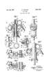
- Fig. l is a sectional side view of the clamp
- Fig. 2 is a front elevation thereof
- Figs. 3, 4 and 5 are sectional views taken along the lines 3-3, 4-4 and 5 5 in the direction of the arrows as indicated in Fig. l;
- Fig. 6 is a side elevation of the clamp
- Fig. 7 illustrates an alternative form of structure.
- the numeral 10 indicates a metallic sleeve, the bore of which is interrupted by a preferably integral abutment in the form of a ange 11. Beyond the latter a guide structure is furnished by preferably providing an axially-extending groove 12 in the bore, which groove may terminate in an end wall 13. It is also preferred to have wing portions 14- extending outwardly from the lower end of sleeve or tube 10.
- a screw-threaded socket member 15 has a diameter such that it may be accommodated within the bore of the sleeve at a point above flange 11. Adjacent its lower end this member may have an out-struck portion 16 which rides within groove 12 to furnishin cooperation with the same-a key and keyway structure preventing a rotation of the socket member with respect to the sleeve.
- the closing wall or stop 13 is conveniently provided. This may be accomplished by resorting to any acceptable technique lto extend portion 13 in the direction of the axis of the assembly and thus overlie part 16.
- Socket member 15 carries, as a preferably integral part, a wire-engaging and clamping jaw. That jaw, as shown, embraces an outwardly-extending portion 17 continued in the form of angularly-extending faces 18, the last two of which converge to dene a V-notch or trough suitable for the reception and retention of a cable or lead 19.
- the jaw provided by portion 17 and its continuations may be rigidiied by a transversely-extending rib or fin portion 20, also integral with member 15 and terminating substantially in line with the upper end of the latter. This iin may be formed with an opening 21.
- the sleeve 10 has its forward face interrupted to permit portions 17 and 18 to extend outwardly of the ICC unit.
- a jaw or supporting part 22 extends outwardly from the sleeve or tube.
- the face 23 of this jaw again preferably includes surfaces extending angularly with respect to each other to generally provide a centering trough or V-shaped configuration opposed to that furnished by the surfaces 18.
- lnwardly of the faces 23 jaw 22 may include an inwardly and downwardly-extending surface 24.
- socket member 15 The threads of socket member 15 are engaged by the threads of a bolt 25.
- the latter may be provided withfa head portion 26 in the form of a ring suitable for engagement with the operative end of an applying or mounting tool (not shown).
- This bolt is furnished with a collar o1' flange 27, having a diameter less than that of the bore of sleeve 10.
- the underface of this flange is conveniently beveled and engaged by a retaining ring 28 seating within a groove formed in the adjacent end of sleeve 10 to prevent a displacement of the bolt.
- a spring 29 is interposed between ange or collar 27 and flange 11. In the position of the parts as shown in Fig. l, this spring is substantially fully expanded so as not to exert unnecessary tension.
- a wing portion 30 may extendv outwardly from the side face of sleeve 10 and be integral therewith. As shown especially in Figs. 3, 4 and S, this wing portion will include side walls 31, spaced from each other, and which side walls may be notched in their upper edges as indicated at 32.
- a bolt has its shank 33 extending through an opening provided in the wing portion between walls 31. Thisbolt is secured in position by, for example, a nut and washer assembly 34.
- the inner end of the bolt terminates in a preferably ringshaped body 35, which includes at its end a head por-tion 36. The length of the latter is greater than the width of ring 35. Therefore, its ends overlap walls 31 and the notched edges 32 thereof.
- the inner end of bolt 25, preferably terminates substantially in the upper plane of tube or sleeve 10.
- the side walls of the latter above the supporting or jaw portion 22 may generally define an ellipse.
- the adjacent surfaces of socket member 15 may include an identical configuration. It will be understood, if such a structure is resorted to, any danger of the socket member oscillating or turning with respect to the sleeve will be prevented. This, of course, will also be prevented by the key and keyway structure and could be satisfactorily counteracted by having the surfaces of ⁇ the sleeve member and socket of any desirable non-circular outline.
- Bolt 25 will be actuated to assure a substantial separation of jaw surfaces 18 from surfaces 23. This will provide clearance such that an operator who may be gripping bolthead 26 by means of a hot stick will be able to move the guiding portion 17 of the jaw assembly over and into engagement with the lead 19. Thereupon, the latter will shift to rest between converging surfaces 18, as shown in Fig. l. If, now, by engaging the lead, or by the use of a suitable instrument, sleeve 10 is prevented from rotating and bolt 25 is rotated, the jaw structure 17--18 will be drawn towards the jaw structure 22. This action will serve to clamp between these elements the lead 3 19. Thereforaagaina properly rm mechanical and electrical connection will be established, such that current may llow to or from lead 19 and from or to a lead associated with loop 35.
- a line clamp including in combination a sleeve, an abutment extending into the bore of said sleeve, a socket member slidably mounted by extending into the sleeve bore, a key and keyway forming parts of said sleeve and member to prevent relative rotation thereof, a bolt extending from a point beyond said sleeve into the bore of said member, such bore and 'bolt being formed with cooperating screw-threads, a ange extending outwardly from said bolt and within the bore of said sleeve, a spring interposed between sai'd abutment and flange, means mounted by said sleeve and engaging said ange to ⁇ prevent an outward displacement of said bolt by said spring and jaws extending outwardly nfrom said sleeve and member and cooperating to grip between them a cable.
- said key and keyway embracing an outstruck portion adjacent one end of said member, said sleeve being formed with a groove between said ⁇ abutment and the end adjacent which said A 4member is disposed, said groove extending axially of said sleeve and ⁇ sldably receiving said abutment and an end wall forming a part of said sleeve and closing said groove ⁇ to prevent said outstruck portion from riding out of the same.
Description
S. P. BECKER Oct. 29, 1957 LINE CLAMP Filed April 26, 1955 fw Z RM1/MVS. mz u m vv/.Ww H, am [m44 W ilnited States Patent() LINE CLAMP Stephen P. Becker, Poughkeepsie, N. Y., assignor to Fargo Mfg. Company, Inc., Poughkeepsie, N. Y., a corporation of New York Application April 26, 1955, Serial No. 503,889
2 Claims. (Cl. 339-264) This invention relates to a structurally and functionally improved clamp for mechanically and electrically connect-V ing electrical lines to each other, which lines may carry high voltage.
The present appiication is a continuation-in-part of my earlier application for patent entitled High-Voltage Clamp, Serial No. 170,653,1iled June 27, 1950, now abandoned.
Among the objects of the present invention are those of providing a clamp for electrical transmission lines, which clamp may readily be manipulated to electrically and mechanically secure lines to each other, or to disconnect those lines and which, in use, will maintain the connection for long periods of time with freedom from all difliculties, the clamp being simple in design and operation. n
With these and other objects in mind, reference is had to the attached sheet of drawing, illustratingy practical embodiments of the invention, and in which:
Fig. l is a sectional side view of the clamp;
Fig. 2 is a front elevation thereof;
Figs. 3, 4 and 5 are sectional views taken along the lines 3-3, 4-4 and 5 5 in the direction of the arrows as indicated in Fig. l;
Fig. 6 is a side elevation of the clamp; and
Fig. 7 illustrates an alternative form of structure.
In these views the numeral 10 indicates a metallic sleeve, the bore of which is interrupted by a preferably integral abutment in the form of a ange 11. Beyond the latter a guide structure is furnished by preferably providing an axially-extending groove 12 in the bore, which groove may terminate in an end wall 13. It is also preferred to have wing portions 14- extending outwardly from the lower end of sleeve or tube 10.
A screw-threaded socket member 15 has a diameter such that it may be accommodated within the bore of the sleeve at a point above flange 11. Adjacent its lower end this member may have an out-struck portion 16 which rides within groove 12 to furnishin cooperation with the same-a key and keyway structure preventing a rotation of the socket member with respect to the sleeve. After these parts are operatively associated, the closing wall or stop 13 is conveniently provided. This may be accomplished by resorting to any acceptable technique lto extend portion 13 in the direction of the axis of the assembly and thus overlie part 16.
Socket member 15 carries, as a preferably integral part, a wire-engaging and clamping jaw. That jaw, as shown, embraces an outwardly-extending portion 17 continued in the form of angularly-extending faces 18, the last two of which converge to dene a V-notch or trough suitable for the reception and retention of a cable or lead 19. The jaw provided by portion 17 and its continuations may be rigidiied by a transversely-extending rib or fin portion 20, also integral with member 15 and terminating substantially in line with the upper end of the latter. This iin may be formed with an opening 21.
As shown, the sleeve 10 has its forward face interrupted to permit portions 17 and 18 to extend outwardly of the ICC unit. At the base of .this interruption, a jaw or supporting part 22 extends outwardly from the sleeve or tube. The face 23 of this jaw again preferably includes surfaces extending angularly with respect to each other to generally provide a centering trough or V-shaped configuration opposed to that furnished by the surfaces 18. lnwardly of the faces 23 jaw 22 may include an inwardly and downwardly-extending surface 24.
l The threads of socket member 15 are engaged by the threads of a bolt 25. The latter may be provided withfa head portion 26 in the form of a ring suitable for engagement with the operative end of an applying or mounting tool (not shown). This bolt is furnished with a collar o1' flange 27, having a diameter less than that of the bore of sleeve 10. The underface of this flange is conveniently beveled and engaged by a retaining ring 28 seating within a groove formed in the adjacent end of sleeve 10 to prevent a displacement of the bolt. A spring 29 is interposed between ange or collar 27 and flange 11. In the position of the parts as shown in Fig. l, this spring is substantially fully expanded so as not to exert unnecessary tension.
To furnish a clamp for a lead or tap-off line, a wing portion 30 may extendv outwardly from the side face of sleeve 10 and be integral therewith. As shown especially in Figs. 3, 4 and S, this wing portion will include side walls 31, spaced from each other, and which side walls may be notched in their upper edges as indicated at 32. A bolt has its shank 33 extending through an opening provided in the wing portion between walls 31. Thisbolt is secured in position by, for example, a nut and washer assembly 34. The inner end of the bolt terminates in a preferably ringshaped body 35, which includes at its end a head por-tion 36. The length of the latter is greater than the width of ring 35. Therefore, its ends overlap walls 31 and the notched edges 32 thereof.
ln conclusion, it will be observed that the inner end of bolt 25, preferably terminates substantially in the upper plane of tube or sleeve 10. Also, the side walls of the latter above the supporting or jaw portion 22 may generally define an ellipse. Similarly, the adjacent surfaces of socket member 15 may include an identical configuration. It will be understood, if such a structure is resorted to, any danger of the socket member oscillating or turning with respect to the sleeve will be prevented. This, of course, will also be prevented by the key and keyway structure and could be satisfactorily counteracted by having the surfaces of `the sleeve member and socket of any desirable non-circular outline.
In use, it will be assumed that a lead (not shown) is introduced through the loop or ring 35 of the bolt. That lead will rest within notch surfaces 32 and as the nut assembly 34 is tightened, head portion 36 will engage the outer peripheral surface of the lead to draw the latter into firm contact with the outer edges of walls 31. This action will be continued until the parts are clamped against movement. Under those circumstances, the lead will be in proper electrical connection with the tube 10. The clamp is now ready for application to a current-supplying or receiving lead, such as 19. That line may customarily be supported in a generally horizontal plane.
Bolt 25 will be actuated to assure a substantial separation of jaw surfaces 18 from surfaces 23. This will provide clearance such that an operator who may be gripping bolthead 26 by means of a hot stick will be able to move the guiding portion 17 of the jaw assembly over and into engagement with the lead 19. Thereupon, the latter will shift to rest between converging surfaces 18, as shown in Fig. l. If, now, by engaging the lead, or by the use of a suitable instrument, sleeve 10 is prevented from rotating and bolt 25 is rotated, the jaw structure 17--18 will be drawn towards the jaw structure 22. This action will serve to clamp between these elements the lead 3 19. Thereforaagaina properly rm mechanical and electrical connection will be established, such that current may llow to or from lead 19 and from or to a lead associated with loop 35.
It will 4be understood, even if line `19 is not :properly disposed with Vrespect to the :jaw surfaces, an acceptable engaging 'and clamping structure fwill nevertheless be furnished. This 4has been illustrated in Fig. A6, in which line or cable 19 has been shown as displaced into engagement with surface 24. It is apparent that sopositioned, the cable will nevertheless be firmly gripped. Also, by this struc ture a design is furnished which will prevent any jamming of the parts, even if the lcable or an auxiliary strand is shifted to too great an extent inwardly toward the axis of the device. In any event, it will be appreciated that ns the jaws are tightened to rmly engage the cable or line 19, collar or flange 27 of the bolt 25 will move inwardly as the Aresistance yto movement on the part of jaws 17-1'8 increases beyond a certain fextent. Therefore, the grip on the 'cable or line kexerted by the jaws will actually be equal to the degree 'of compression of the spring, dependent upon the amount bolt 25 has been tightened. This construction will also provide a yieldable engagement which will vary according to the :tension or strain which is exerted upon the parts.
In the form of structure shown in Fig. 7, the same arrangement of `parts as that heretofore described has been illustrated. However, in this construction, the tube mem* `ber 10 providing the faces 23 of the lower jaw is furnished with wing portions 40. These will serve as guides in engagement with the wire in order to position the latter properly between the jaws. It is apparent that by this construction the wire cannot be displaced to a position where it -will `be locked to the rear of the groove or engaging surfaces,
Thus, among others, the several objects of the invention as specifically aforenoted are achieved. Obviously, numerous changes in construction and rearrangement of the parts may be resorted to without departing from the spirit of the invention as defined by the claims.
I claim:
1` A line clamp including in combination a sleeve, an abutment extending into the bore of said sleeve, a socket member slidably mounted by extending into the sleeve bore, a key and keyway forming parts of said sleeve and member to prevent relative rotation thereof, a bolt extending from a point beyond said sleeve into the bore of said member, such bore and 'bolt being formed with cooperating screw-threads, a ange extending outwardly from said bolt and within the bore of said sleeve, a spring interposed between sai'd abutment and flange, means mounted by said sleeve and engaging said ange to `prevent an outward displacement of said bolt by said spring and jaws extending outwardly nfrom said sleeve and member and cooperating to grip between them a cable.
2. In a line clamp as 'specified in claim l, said key and keyway embracing an outstruck portion adjacent one end of said member, said sleeve being formed with a groove between said `abutment and the end adjacent which said A 4member is disposed, said groove extending axially of said sleeve and `sldably receiving said abutment and an end wall forming a part of said sleeve and closing said groove `to prevent said outstruck portion from riding out of the same.
References Cited in the le of this patent UNTTED STATES PATENTS 1,594,925 Chandler Aug. 3, 1926 1,932,010 Becker Oct. 24, 1933 1,990,928 Bodendieek Feb. l2, 1935 2,016,749 Mack Oct. 8, 1935 2,319,602 Hendley May 18, 1943 2,422,379 Westman June 17, 1947 2,631,346 Wengen Mar. 17, 1953 FOREIGN PATENTS 503,567 Canada June 8, 1954
Priority Applications (1)
| Application Number | Priority Date | Filing Date | Title |
|---|---|---|---|
| US503889A US2811703A (en) | 1955-04-26 | 1955-04-26 | Line clamp |
Applications Claiming Priority (1)
| Application Number | Priority Date | Filing Date | Title |
|---|---|---|---|
| US503889A US2811703A (en) | 1955-04-26 | 1955-04-26 | Line clamp |
Publications (1)
| Publication Number | Publication Date |
|---|---|
| US2811703A true US2811703A (en) | 1957-10-29 |
Family
ID=24003943
Family Applications (1)
| Application Number | Title | Priority Date | Filing Date |
|---|---|---|---|
| US503889A Expired - Lifetime US2811703A (en) | 1955-04-26 | 1955-04-26 | Line clamp |
Country Status (1)
| Country | Link |
|---|---|
| US (1) | US2811703A (en) |
Cited By (22)
| Publication number | Priority date | Publication date | Assignee | Title |
|---|---|---|---|---|
| US2867787A (en) * | 1958-03-11 | 1959-01-06 | Anderson Electric Corp | Hot line clamp |
| US2958067A (en) * | 1958-11-17 | 1960-10-25 | Kearney James R Corp | Wire clamp |
| US3132914A (en) * | 1961-08-29 | 1964-05-12 | Fargo Mfg Co Inc | Clamp assembly |
| US3253215A (en) * | 1959-09-30 | 1966-05-24 | Automatic Switch Co | Overload current detecting device having laminated split core means coupled to a holding circuit with indicator |
| US3629805A (en) * | 1969-02-06 | 1971-12-21 | Anderson Electric Corp | Hot line clamp |
| DE2455408A1 (en) * | 1973-11-23 | 1975-05-28 | John Lewis Hartstone | CARRYING DEVICE |
| US4646452A (en) * | 1983-11-21 | 1987-03-03 | Plasti-Max S.R.L. | Mark applicable to general articles with blocking device against abusive removal |
| US4846725A (en) * | 1988-04-15 | 1989-07-11 | Houston Industries Incorporated | Self-latching power line clamp |
| US5556299A (en) * | 1995-03-23 | 1996-09-17 | Houston Industries Incorporated | Self-latching clamp for power lines |
| US6494726B1 (en) * | 2001-11-26 | 2002-12-17 | Electric Motion Company, Inc. | Cable rack clamp |
| WO2008013901A2 (en) * | 2006-07-26 | 2008-01-31 | Fci Americas Technology, Inc. | Conductor connection |
| US20080026644A1 (en) * | 2006-07-26 | 2008-01-31 | De France Robert V | Conductor Connection |
| US20080026600A1 (en) * | 2006-07-26 | 2008-01-31 | De France Robert V | Conductor Connection |
| US20080194153A1 (en) * | 2007-02-13 | 2008-08-14 | International Business Machines Corporation | Spring Loaded Parallel Pad Clamp |
| US8512070B2 (en) | 2010-12-03 | 2013-08-20 | Hubbell Incorporated | Spring loaded clamp |
| US8932087B2 (en) | 2012-05-08 | 2015-01-13 | Thomas & Betts International, Inc. | Hot line stirrup connector |
| US9812794B2 (en) | 2015-06-10 | 2017-11-07 | Thomas & Betts International Llc | Stamped hotline clamp |
| US10095001B2 (en) | 2016-07-29 | 2018-10-09 | Hubbell Incorporated | Spring assist cable clamps |
| US10557568B2 (en) | 2017-09-15 | 2020-02-11 | Hubbell Incorporated | Multi-sided cable clamps |
| US10649169B2 (en) | 2017-08-16 | 2020-05-12 | Hubbell Incorporated | Sliding jaw drop clamp |
| US10705301B2 (en) | 2017-10-22 | 2020-07-07 | Hubbell Incorporated | Spring assist cable clamp |
| US10795108B2 (en) | 2016-07-29 | 2020-10-06 | Hubbell Incorporated | Spring assist cable clamps |
Citations (8)
| Publication number | Priority date | Publication date | Assignee | Title |
|---|---|---|---|---|
| US1594925A (en) * | 1922-09-20 | 1926-08-03 | Ohio Brass Co | Conductor clamp |
| US1932010A (en) * | 1931-11-28 | 1933-10-24 | Stephen P Becker | Line tap connecter |
| US1990928A (en) * | 1928-01-05 | 1935-02-12 | Tips Tool Company Inc | Wire clamp |
| US2016749A (en) * | 1933-04-08 | 1935-10-08 | Memco Engineering & Mfg Co Inc | Device for attaching leads to line wires |
| US2319602A (en) * | 1941-03-10 | 1943-05-18 | Cornelia S Hendley | Clamp |
| US2422379A (en) * | 1944-08-30 | 1947-06-17 | Bendix Aviat Corp | Electric bushing |
| US2631346A (en) * | 1949-12-29 | 1953-03-17 | Fargo Mfg Co Inc | Messenger wire clamp |
| CA503567A (en) * | 1954-06-08 | P. Becker Stephen | High-voltage clamp |
-
1955
- 1955-04-26 US US503889A patent/US2811703A/en not_active Expired - Lifetime
Patent Citations (8)
| Publication number | Priority date | Publication date | Assignee | Title |
|---|---|---|---|---|
| CA503567A (en) * | 1954-06-08 | P. Becker Stephen | High-voltage clamp | |
| US1594925A (en) * | 1922-09-20 | 1926-08-03 | Ohio Brass Co | Conductor clamp |
| US1990928A (en) * | 1928-01-05 | 1935-02-12 | Tips Tool Company Inc | Wire clamp |
| US1932010A (en) * | 1931-11-28 | 1933-10-24 | Stephen P Becker | Line tap connecter |
| US2016749A (en) * | 1933-04-08 | 1935-10-08 | Memco Engineering & Mfg Co Inc | Device for attaching leads to line wires |
| US2319602A (en) * | 1941-03-10 | 1943-05-18 | Cornelia S Hendley | Clamp |
| US2422379A (en) * | 1944-08-30 | 1947-06-17 | Bendix Aviat Corp | Electric bushing |
| US2631346A (en) * | 1949-12-29 | 1953-03-17 | Fargo Mfg Co Inc | Messenger wire clamp |
Cited By (31)
| Publication number | Priority date | Publication date | Assignee | Title |
|---|---|---|---|---|
| US2867787A (en) * | 1958-03-11 | 1959-01-06 | Anderson Electric Corp | Hot line clamp |
| US2958067A (en) * | 1958-11-17 | 1960-10-25 | Kearney James R Corp | Wire clamp |
| US3253215A (en) * | 1959-09-30 | 1966-05-24 | Automatic Switch Co | Overload current detecting device having laminated split core means coupled to a holding circuit with indicator |
| US3132914A (en) * | 1961-08-29 | 1964-05-12 | Fargo Mfg Co Inc | Clamp assembly |
| US3629805A (en) * | 1969-02-06 | 1971-12-21 | Anderson Electric Corp | Hot line clamp |
| DE2455408A1 (en) * | 1973-11-23 | 1975-05-28 | John Lewis Hartstone | CARRYING DEVICE |
| US4098479A (en) * | 1973-11-23 | 1978-07-04 | John, Lewis Harstone | Bracket |
| US4646452A (en) * | 1983-11-21 | 1987-03-03 | Plasti-Max S.R.L. | Mark applicable to general articles with blocking device against abusive removal |
| US4846725A (en) * | 1988-04-15 | 1989-07-11 | Houston Industries Incorporated | Self-latching power line clamp |
| US5556299A (en) * | 1995-03-23 | 1996-09-17 | Houston Industries Incorporated | Self-latching clamp for power lines |
| US6494726B1 (en) * | 2001-11-26 | 2002-12-17 | Electric Motion Company, Inc. | Cable rack clamp |
| US20080026600A1 (en) * | 2006-07-26 | 2008-01-31 | De France Robert V | Conductor Connection |
| US7766702B2 (en) | 2006-07-26 | 2010-08-03 | Burndy Technology Llc | Conductor connection |
| US20080026613A1 (en) * | 2006-07-26 | 2008-01-31 | De France Robert V | Conductor Connection |
| WO2008013901A2 (en) * | 2006-07-26 | 2008-01-31 | Fci Americas Technology, Inc. | Conductor connection |
| WO2008013901A3 (en) * | 2006-07-26 | 2008-07-03 | Fci Americas Technology Inc | Conductor connection |
| US20080026644A1 (en) * | 2006-07-26 | 2008-01-31 | De France Robert V | Conductor Connection |
| US7485014B2 (en) * | 2006-07-26 | 2009-02-03 | Fci Americas Technology, Inc. | Conductor connection |
| US7498528B2 (en) | 2006-07-26 | 2009-03-03 | Fci Americas Technology, Inc. | Conductor connection |
| US20090130872A1 (en) * | 2006-07-26 | 2009-05-21 | De France Robert V | Conductor connection |
| US7614923B2 (en) | 2006-07-26 | 2009-11-10 | Fci Americas Technology, Inc. | Conductor connection |
| US20080194153A1 (en) * | 2007-02-13 | 2008-08-14 | International Business Machines Corporation | Spring Loaded Parallel Pad Clamp |
| US7666024B2 (en) | 2007-02-13 | 2010-02-23 | Burndy Technology Llc | Spring loaded parallel pad clamp |
| US8512070B2 (en) | 2010-12-03 | 2013-08-20 | Hubbell Incorporated | Spring loaded clamp |
| US8932087B2 (en) | 2012-05-08 | 2015-01-13 | Thomas & Betts International, Inc. | Hot line stirrup connector |
| US9812794B2 (en) | 2015-06-10 | 2017-11-07 | Thomas & Betts International Llc | Stamped hotline clamp |
| US10095001B2 (en) | 2016-07-29 | 2018-10-09 | Hubbell Incorporated | Spring assist cable clamps |
| US10795108B2 (en) | 2016-07-29 | 2020-10-06 | Hubbell Incorporated | Spring assist cable clamps |
| US10649169B2 (en) | 2017-08-16 | 2020-05-12 | Hubbell Incorporated | Sliding jaw drop clamp |
| US10557568B2 (en) | 2017-09-15 | 2020-02-11 | Hubbell Incorporated | Multi-sided cable clamps |
| US10705301B2 (en) | 2017-10-22 | 2020-07-07 | Hubbell Incorporated | Spring assist cable clamp |
Similar Documents
| Publication | Publication Date | Title |
|---|---|---|
| US2811703A (en) | Line clamp | |
| US1712108A (en) | Connecter | |
| US6186391B1 (en) | Welding assembly apparatus for welding fasteners to a component and method of welding fasteners to the component | |
| US3075166A (en) | Hot line clamp | |
| US1710416A (en) | Connecter | |
| US3026368A (en) | Conductor clamp assembly for use on pole top insulators | |
| US2064440A (en) | Electric connecter | |
| US2867787A (en) | Hot line clamp | |
| US3787948A (en) | Wire nut wrench | |
| US2046942A (en) | Electrical connecter | |
| US2958067A (en) | Wire clamp | |
| US3132914A (en) | Clamp assembly | |
| US1865003A (en) | Electric welding tong | |
| US2397390A (en) | Hot line clamp | |
| US3215811A (en) | Electrode holder assembly | |
| US4778413A (en) | Ground clamp for a welding apparatus | |
| US2397097A (en) | Separable connector for electrical apparatus | |
| USRE28877E (en) | Electric cable connector | |
| US2739999A (en) | Service entrance head | |
| US2400285A (en) | Welder's electrode holder | |
| KR200413407Y1 (en) | Connection structure for cable of welding machine | |
| US2114736A (en) | Electrical connecter | |
| US2583440A (en) | Electric fuses and releasable connectors | |
| US1677326A (en) | Connecter | |
| US2163677A (en) | Connector |