US2828362A - Digit data transmission system - Google Patents
Digit data transmission system Download PDFInfo
- Publication number
- US2828362A US2828362A US560966A US56096656A US2828362A US 2828362 A US2828362 A US 2828362A US 560966 A US560966 A US 560966A US 56096656 A US56096656 A US 56096656A US 2828362 A US2828362 A US 2828362A
- Authority
- US
- United States
- Prior art keywords
- signal
- character
- lead
- error
- gate
- Prior art date
- Legal status (The legal status is an assumption and is not a legal conclusion. Google has not performed a legal analysis and makes no representation as to the accuracy of the status listed.)
- Expired - Lifetime
Links
Images
Classifications
-
- H—ELECTRICITY
- H04—ELECTRIC COMMUNICATION TECHNIQUE
- H04L—TRANSMISSION OF DIGITAL INFORMATION, e.g. TELEGRAPHIC COMMUNICATION
- H04L1/00—Arrangements for detecting or preventing errors in the information received
- H04L1/12—Arrangements for detecting or preventing errors in the information received by using return channel
- H04L1/16—Arrangements for detecting or preventing errors in the information received by using return channel in which the return channel carries supervisory signals, e.g. repetition request signals
- H04L1/18—Automatic repetition systems, e.g. Van Duuren systems
Description
ca.A P. DARWIN ET AL 2,828,362
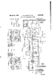
DIGIT DATA TRANSMISSION SYSTEM March 25, 1958 9 Sheets-Sheet 1 Filed Jan. 24, 1956 G. R DARWIN W. A. MALTHANER J. E. SCHWENKEI? /N VEN TORS BY /AJA v ,arrow/wwv G.- P. DARWIN ETAL 2,828,362
DIGIT DATA TRANSMISSION SYSTEM March 25, 1958 9 Sheets-Shea?l 2 Filed Jan. 24, 1956 @9%- muon #Guam .ANN @Qn QMQOQMQ QN WN www mmm Wmml Umm.
w R m R E O m M m H A Mx s A5 WJ# R m DVD w. w si G. P. DARWIN ET AL DIGIT DATA TRANSMISSION SYSTEM March 25, 1958 Filed Jari. 24, 195e 9 Sheets-Sheet 3 .Ewmw #31? NOM.
k www mmm QQ hm.
www m9, 2h.
vm non lam.. I .54* www.
Mmm,
G. P. DARWIN /NVENroRs w. A. MALrHA/vE/e J E. .scHwE/wrE/P (/m 1 /M AroR/VEV G. P. DARWIN ETAL I DIGIT DATATRANSMISSION SYSTEM March 25, 1958 Filed Jan. 24, 195s 9 Sheets-Sheet 4 QOQQM @REVE Sv mvv mmm. www.
NNW www MQQU NNN
www
G. R DARWIN n R Em.. m NK O AN T www M #Hb .Ns AE. WJ. m T m V w 'March 25, 1958 V G. P. DARWIN E1- Al.- 2,828,362
DIGIT DATA TRANSMISSION SYSTEM Filed Jan. 24, 1956 9 Sheets-Sheet 5 vbm.
Arrow/EK Mardi 25, 1958 G. P. DARWIN ET A1. 2,828,362
DIGIT DATA TRANSMISSION SYSTEM 9 Sheets-Sheet 6 Filed Jan. 24, 1956 S Si MAL THANER A r 'rom/EV March 25, 1958 G. P. DARWIN ET AL 2,828,362
' DIGIT DATA TRANSMISSION .SYSTEM l E? Shee'ts-Sheet 7 Filed Jan. 24, 1956 :6mm A 5m MT j om.
Y RM
Sm .33E
um) :6mm GA AA A A AA A M S Q m k DOK DO w JUUULF J. E. SCHWENKER 5V 4%# March 25, 1958 G. P. DARWIN ETAL 2,828,362
` DIGIT DATA TRANSMISSION SYSTEM Filed Jan. 24, 1956 9 Sheets-Sheet 8 AAA VV AAA VV G. P. DARWIN ET AL 2,828,362
DIGIT DATA TRANSMISSION SYSTEM March 25, 1958 9 Sheets-Sheet 9 Filed Jan. 24. 1956 AAA V" xvmm.
PNNL
G. P. DARWIN /NVENTORS W A.,MALTHNER J. 5. SCHWEN/(ER ATTORNEY United States yatent O DEGIT DATA TRANSMISSION SYSTEh/l George P. Darwin, Summit, William A. Maltllaner, New Providence, and lohn E. Sehwenker, Gillette, N. Il., assiguors to Bell Telephone Laboratories, incorporated, New York, N. Y., a corporation of New York Application January 2d, 1956, Serial No. 560,966
38 Claims. (Cl. Fill- 2) This invention relates to transmission of data and particularly to high speed coded digital data transmission adapted for use between subscriber stations in a telephone system.
Progress in the computer and related fields has developed to such an extent that knowledge may now be converted to digital form and concentrated in a storage unit to be read therefrom at will, rapidly and with a high degree of accuracy. With the growth of this art and the ever increasing use of its products, there is a recognition of the need for rapid interchange of such stored knowledge between units in various locations, in order, for example, to keep all phases of a companys functions coordinated.
lt is a general object of this invention to enable rapid and accurate transfer of stored data from one location to another by employment of telephone transmission facilities.
Data transmission systems are well known in the telegraphic and related arts. Such systems in present use, however, do not achieve the high speed of operation required for economical transfer over long distances utilizing transmission systems such as telephone toll lines. Likewise means are not available in present systems for providing a complete check on the accuracy of transmitted data to assure that it is correct and, if not, to correct it automatically' and thereafter to transcribe it at the receiving end in a form of memory storage compatible with associated equipment, such as a computer, which will utilize the data.
One preferred embodiment of this invention, described hereinafter, employs a signaling arrangement in which code and information signals in the form of binary digits are transmitted by means of double sideband, carrier current signals produced by pulse code, amplitude modulation without synchronization of the carrier current sources. The band is chosen such that low frequency phase distortion is minimized and excessive frequency shift is controlled by proper maintenance of the carrier terminals in the telephone transmission medium. y
In accordance with one aspect of this invention, data to be transferred rapidly over a long distance is recorded on magnetic tape or other suitable medium. Combination transmitter-receiver units, referred to hereinafter as data subsets, are associated with subscriber telephone substations at calling and called locations so that the party desiring to transmit data may advise the called party by placing a usual call over the telephone line. The transmitting party places the medium holding the recorded intelligence in the data subset associated with his telephone subset, and upon establishing a connection with the called party, he switches his data subset into the telephone line path in a transmitting condition. The data subset at the receiving end is switched into the line by the called party and set to receive the data transmitted over the line. Transmission begins immediately, and both data subsets monitor the data as it is transmitted and received respectively. The message data is interspersed with code signals ICAC directing internal operation of the data subsets to synchronize, stop and restart them and to cause them to formulate additional directive signals.
The entire message is transmitted in blocks of intelligence characters of any designated length, such asa typewriter line of type, after each of which a code signal stops the transmitter. 'If the block was received correctly, the receiving unit returns an acknowledgment so indicating. The acknowledgment activates the transmitter to transmit the next block of data. lf the receiving unit finds an error among the transmitted intelligence characters of a block of data, it will return to the transmitting unit at the end of the block, an acknowledgment evidencing the presence of an error. The transmitting unit, upon receipt of this signal, will retransmit the same block. Thus, errors due to circuit noise are eliminated. If an error appears during a second transmission of a particular block, both data subsets vare automatically shut olf and an alarm sounded. Errors on the storage medium in the transmitting unit will be recognized by the transmitting unit which, in turn, will advise the receiving unit merely to note the error on the output medium. Transfer of an erroneous character to the storage medium to be placed in the transmitting unit may be noted by the printing of a special code signal at the end of the information block containing the error, after which the correct block of information is transferred to the storage medium. The special code signal is recognized by the transmitting unit which responds thereto by stopping transmission until the block in error has been passed through the unit.
In this fashion a complete, accurate transfer of digital information is accomplished with a minimum of actual operating time in which the telephone line is occupied.
A feature of this invention is a signal transmitting device arranged to initiate the transmission of signals over a telephone line upon actuation of the device, to stop the transmission internally in response to a particular code signal, and to restart transmission upon-receipt over the transmission path of a particular code signal.
Another feature of the invention is the provision of signal responsive means associated with a transmitter for stopping the transmission of carrier current signals after each block of transmitted data and for restarting transmission upon receipt of an acknowledgment signal from the receiving end of the transmission line.
Another feature of the invention is a signal receiver responsive to pulse code, amplitude modulated, double sideband, carrier current signals including stop, start, recording error, transmission error and information digits. According to this feature the signal receiver includes a detector responsive to pulse code, amplitude modulated, double sideband, carrier current signals, a synchronizing and checking circuit, a control circuit and a special code generator. Y
A further feature of this invention is the provision of carrier current signal transmitting means associated with a signal receiver according to the preceding paragraph for transmitting an acknowledgment code signal to the originating transmitter to permit transmission of Vcarrier current signals from the originating end of the line over which signals are being received and transmitted to continue or to cause the originating transmitter to retransmit certain data. Y
A still further feature of this invention is the provision of signal responsive means associated with a receiver for delineating information signals transmitted thereto over a telephone line and to record such delineations on the output medium along with the information signals. I
These and Y other features of the invention are ernbodied in the system shown schematically in the accompanying drawing. This invention is not limited in application, however, to the system shown but is generally applicable to signaling systems requiring the rapid transmission of intelligence in coded digital form.
VReferring nowto the drawing:
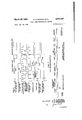
Fig. 1 .isV a. schematic block diagram representing a connection between two subscriber stations in a telephone system, each station having associated therewith a data subset in'accordance with one specic illustrative embodiment of' this invention;
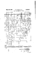
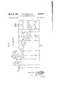
Fig..2'isV a schematic block diagram of one specific transmitter-receiver portion of the data subsets shown in Fig. l;
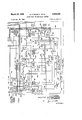
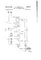
:Fig: 3 is a schematic block diagram of one specific synchronizing and chcckingcircuit portion of the data subsets shown in Fig. 1;
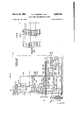
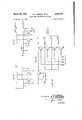
Fig; 4 is a schematic blockrdiagram of one specific control circuit portion of the data subsets shown in Fig. l
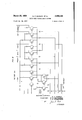
Fig..5 is a schematic block diagram of one specific special code generator portion of the data subsets shown in Fig; l;
Fig. 6v is a Vtime diagram illustrating the sequence of signals utilized in forming directive characters in the data subsets; Y
Fig. -7 illustrates the sequence of directive and intelligence characters appearing on the transmitting magnetic tape utilized in the specific illustrative embodiment of this invention;
Fig. 8 is a representation of the directive characters employed in the specilic illustrative embodiment of this invention;
Fig.V 9 is a key pattern for Figs. 2-5;
Fig. 10 is a schematic representation of one specific embodiment ofa clock generator that may be employed in the synchronizing and checking circuit depicted in Fig. 3; Y
` Fig. ll is a schematic representation of speciiic illustrative embodiments of gate circuits 107 and 111 that may be employed in thetransmitter-receiver depicted in Fig. 2;
Fig. Vl2 is a schematic representaiton of a typical toggle circuit known in the art that may advantageously be employed in the specitic illustrative embodiment of this invention described herein; Fig; 13 is a schematic representation of one specific illustrative embodiment of a parity counter circuit that may be employed in the synchronizing and checking circuit depicted in Fig. 3;
Fig. 14 is a-schematic representation of one specific illustrative embodiment of a coder circuit that may be employed in the special code generator depicted in Fig. 5; and
Fig. l is Va block schematic representation of`one specic illustrative embodiment of this invention showing a connection between a subscriber station A anda subscriber station B, which stations maybe in the same telephone exchange or in exchanges'remote from one another. Associated with'each of the subscriber stations A and B are data subsets 11 and 21, respectively, which maybe switched onto the line 112 in place of the speech subsets 17 and 27 when the circuithas been established between the two stations. The party at station A, for example, may orally advise the party at B that he desires to transmit data. Both parties then switch their respective data subsets onto the line, data subset 11 being in a transmitting condition and data subset 21 in a receiving condition.
The memory storage device in the data subset may be any one of the many familiar storage means in use today such as punched cards, magnetic drum, magnetic tape, etc. InV the specific illustrative embodiment described hereinafter, a magnetic tape is utilized both at the transmitting end `and receiving end. intelligence to be transmitted is transcribed on the tape in a seven element per character binary code. The tape is prepared so as to present the intelligence information in blocks of characters of any designated length. A block size comparable to a standard line, of type is convenient for conversion to a typed message at the receiving end and also permits rapid internal correction of errors. Such a block size is thus utilized in this specic illustrative embodiment of this invention.
A sample section of the magnetic tape utilized in this specific embodiment of this invention is shown in Fig. 7. The characters registered on the tape are shown in a typical arrangement including all of the character types which may be printed on the tape prior to insertion in the tape machine of the transmitting unit. Characters' are printed from left to right on the tape, as shown in Fig. 7, including the Start character, and End of Signaling character EM,vthe characters comprising a block of intelligence and a Stop character. Succeeding blocks of intelligencercharacters are preceded and succeeded by Start and Stop characters respectively. Each character is designated by a single space on the tape in Fig. 7 although it will be appreciated that each character contains a plurality of elements each having one of two states referred to herein as one and zero A Typing Error character TE is shown inserted at the end Vof a block ot intelligence characters but preceding the Stop character for that block. With the tape wound in reverse in the tape machine of thc transmitting unit it can be seen that the Typing Error will be transmitted prior to the block of intelligence containing the error and also that the End of Signaling character EM will succeed the last block of intelligence characters to be transmitted. As the Start and Stop characters are merely the reverse of one another, they will appear in proper order during reverse transmission. The receiving unit 21 also winds Vthe tape in reverse, so that upon readout fromY the receiving unit, the characters will appear in the order shown in Fig. 7.
VThe data subset 11, shown schematically at station Ain Fig. 1, consists of storage and conversion circuits 112, which in this embodiment includes a magnetic tape machine, transmitter-receiver circuits 13, synchronizing and checking circuits 14, control circuits 15 and special code generator circuit 16. Data subset 21 at station B comprisesV circuits 22-26 which correspond to circuits ft2-15, respectively, of data subset 11. These circuits are shown in detail in Figs. 2 through 5. The speech-data switches i3 and 28 provide for switching between tele- Y phone subset and vdata subset, automatically switching from the latter tothe former subset upon completion of data transmission, asV described further below. The switches` 1S and 28 may advantageously comprise a relay having contacts normally connecting th'e telephone subset to the line 112. Upon energization of the relay, as by manually'closing a switchv to apply current to' the relay coil, there occurs a contact transferral connecting the data subset to the line; Removal of this holding current, in a manner known in the art, will automatically transfer the line back tothe telephone subset.
The invention will now be brieiiy described with referencetothe-block schematic of 'Figi l.' The tape box holding the magnetic tape on which inteliigence to be transmitted has been recorded in aV suitable code is fitted to the 'tape machine 12V of stationv A. A blank type is placed in the tape machine 22'of'r`em'ote station B. Itis assumedthat a telephone connection has been completed between subscriber stations A and B and that the party at subset 17,'station A, has advised the party at subset 27, station B, that he desires to transmit data over the line to station B. Bothfp'arties throw-the respective speech -data switches 18 and "2S removing the subsets from lthe line and connecting data subsets 11 and 21 to the line.v `Switches designatedrT and R in FigsxZ-S are actuated by a single control at each data subset to place data Ysubset V1-1.Y in a transmitting condition and. data subset 21 in areceiving condition respectively.
Theftape machine storage unit 12 begins playing 'out tape from which magnetic flux signals are changed to electrical impulses and transferred to the transmitterreceiver circuit 13 and through this circuit to a synchonizing and checking circuit 14 as well as out over the line. These electrical impulses are advantageously of two types or states representing binary elements and are described hereinafter as one or zero A Start character, the rst group of binary digits dening a character to be read from the magnetic tape, is effective to synchronize the operation of data subsets 11 and 21. Each subsequent character will be detected, checked and controlled in synchronism in the respective data subsets, as described hereinafter.
Normal operation The Start character is followed' by a plurality of intelligence characters each arranged in a code form to permit parity checking of the transmitted signals. Parity checking, as used herein, is a means for recognizing correct or erroneous characters by the ratio of one type of element to a second type of element present in each character, or merely the presence of an odd or even number of one element type per character. The code form used in the preferred embodiment is a seven element character containing an odd number of one elements. Should the parity checking circuits detect the presence of an even number of ones ina character, they will react to indicate an error. The parity checking circuits are contained in synchronizing and checking circuits 14 and 24, and serve to count the one elements of each intelligence character signal transmitted between stations A Iand B.
In normal operation it is assumed that no errors are present in the intelligence characters transferred from tape machine 12 and that no errors occur during transmission. In this event, a pluality or block of intelligence signals are transmitted after which a Stop character appears on the transmitting tape and is transmitted. vThe message block in the preferred embodiment may contain any desired number of characters according to the peculiar requirements of a particular application. The elements of the Stop character are passed to the synchronizing and checking circuit 14 which, in turn, will pass a stop signal to the control circuit 15. The control circuit 15 responds thereto by stopping the motion of the transmitting tape, blocking the transmitter and opening. the receiver in circuit 13. Synchronizing and checking circuit 24 in receiving station B responds 'to receipt of a Stop character by placing circuit 23 in a transmitting condition, formulating a Correct character in cooperation with special code generator circuit 25 and transmitting the elements of the Correct character to the transmitting station A. The Correct character is received in data subset 11 at station A and is effective to cause resumption of transmission by that unit. Thereafter both stations revert to the conditions existing prior to appearance of the Stop character.
Error in transmission Errors are most commonly encountered during transmission. This invention is applicable to any telephone transmission path in present use regardless of its limitations, so that errors may occur in transmission primarily from static interference to which impulse signaling is highly vulnerable. Since errors due to transmission interference appear as changes from one form of element to another in an intelligence character, a parity checking circuit will recognize a change in the number of one type of element in a character and register an error signal.
The errorsY described in this case occur during transmission between stations and it is assumed for this eX- planation vthat no error is present on the transmitting tape. Circuits 14 and 15, Fig. 1, will respond to Start and Stop characters as described for normal operation, stop- ..6 y ping the tape and placing circuit 13 in a listening vstate after transmission of a block of'intelligence characters. A parity error in one of the intelligence characters will cause circuits 24, 25 and 26 at station B to coact and produce an Error character which is transmitted back to the listening data subset 11 and also is printed on the output tape in machine 21. Control circuit 15 responds to a signal delivered by circuit 14 upon receipt of the Error character to cause the tape in machine 12 to move in reverse until the Start character preceding the block in error is again read out. The transmitter in circuit 13 remains blocked during this period so that only data subset 11 examines the tape whilek moving in reverse; The Start character initiates a reverse to normal operation; the transmitter is opened and the tape movesforward repeating the identical block previously transmitted in error. Should an error appear in this repeated block, the Error character fom station B is effective to cause the control circuitry in both data subsets 11 and 21 to stop transmission and reception and set off an `alarm at both stations A and B.
Tape error Particles of dust, foreign matter, scratches and other agents may produce an error in a character as it is printed on or read from the transmitting tape. It is necessary that such errors be recognized independently of errors in transmission to prevent fruitless repetition of a block containing a tape error. The parity checking apparatus in circuit 14 examines each intelligence character during transmission in the same fashion as circuit 24 at the receiving end. A tape error will be recognized in circuit 14 so that upon receipt of the Error character from the receiving station B, circuit 14 operates to disregard the Error character, to transmit a Tape Error character and thereafter to cause transmission to continue in the normal manner. The Tape Error character is printed on the receiving tape subsequent to the printing of the Error character thereon, thus identifying an error which has not been corrected.
T ypng error A number of storage mediums are employed in current data systems including punched cards, paper and magnetic tape. The directive and intelligence characters to be stored thereon advantageously may be transferred thereto by employing apparatus akin to a typewriter. The typist, upon recognition of an error in a block of intelligence, adds a Typing Error character to the portion of the block completed and proceeds to retype the block correctly. The printed tape is wound on a reel or spool in this embodiment of the invention in such a manner that during transmission the tape is read out in reverse. The receiving station, in turn, prints on the receiving tape in reverse so that it is available'to be read out of the receiving unit in proper order for transcription in other forms as desired.
Upon readout in reverse by the transmitting unit, therefore, the correctly typed block of information is trans'- mitted before the Typing Error character. Circuitl 14 responds to receipt of the Typing Error character to cause control circuit 15 to block the transmitter of circuit 13. Readout continues with the block of intelligence containing the error passing only through data subset 11 and not out on the line.
An End of Signaling character may also be printed on the transmitting tape in response to receipt of which both data subsets will stop provided no error was present in the priorly transmitted intelligence block. Character marks formed in the receiving unit are printed on the output tape to deiine each character for ease of transcription. p g Y The detailed circuits of the specific illustrative embodiment of the data subset in accordance with this `invention depicted in Fig. l are shown in Figs. 2-5 which advantageously may be consulted together inthe pattern shown lin Fig'. Logical circuitry, that is,rgating circuits" of the coincidence or anticoincidence variety, are employed throughout Figs.l 2-5. Such gating circuits arerwell known in the art and take a plurality of forms to suit the intended result. Those gating circuits indicated as And circuits in Figs. 2-5 may comprise arrangements of diodes and/ or transistors such that signals on all of the input leads simultaneously will produce a signal on the single output lead. Or circuits may comprise arrangements of similar components to produce an output signal when signals are applied to any one or all of the input leads. Gates marked INH indicate that a signal applied to one of two input leads will produce a signal on the output lead unless a signal also appears on the-other inhibit input lead. Gates or switches 107 and 111 may comprise an arrangement of transistor circuits to form a pair of coincidence gates and a switch such that enabling one gate inhibits the other gate. Specific exemplary gating circuits 107 and 111 are shown in Fig. l1, though other gate circuits known in the art could also be employed.
Flipflop circuits are used as toggle switches, setting themselves upon receipt of a signal on one input lead and resetting in response to a signal on a second input lead. A typical toggle circuit that we have advantageously used in this specific embodiment of this invention is shown in Fig. l2, though other toggle circuits could also be employed.
A clock generator 206, Fig. 3, comprising in this speciic embodiment of this invention a 600 cycle multivibrator, is utilized in the synchronizing and checking circuits 14 and 24 to provide aconstant source of pulses in step with the intelligence signals to operate the checking apparatus. A synchronizing circuit is included in the multivibrator circuit to keep the multivibrator in step with the intelligence by adjusting the phase of the multivibrator output each time there is a change in the type of element transmitted; i. e., a change from a one to a zero or vice versa.
A detailed circuit of one illustrative clock generator 206 which performs this function and may be employed in this embodiment is shown in Fig. l0. The information signal is fed into a phase spliter including transistor 601 which in turn triggers a monostable multivibrator 602. Multivibrator 602 provides a pulse lasting for one half bit after a change in information from a one to a zero or vice versa. This pulse controls transistor 603 which grounds the base of transistor 604 (formingpart of a free running multivibrator 605) for the duration' of the pulse. This Vprevents the multivibrator 605 from free running during the pulse and allows it to start exactly in phase at the end of the pulse. The output from multivibrator 605' is used as the input to further circuitry to provide the required output timing signals.
A pulse counting circuit 207, Fig. 3, operates to count pulses emanating from the clock generator 206, Fig. 3, over lead 233, through inhibitor 245 and over lead 247, which pulses correspond vto the number of elements in each intelligence character. As seven elements per character are utilized in the preferred embodiment of this invention, the pulse counter 207 will count seven pulses and then emit a character marking pulse and a word pulse, the signicance of which is described hereinafter. vThepulse counter 207 may advantageously cornprise a ferroelectric condenser which passes accurately measured current pulses to a second condenser which in turn builds up to a critical point and fires through a rectiiier circuit to produce the desired outputpulses at the required point in time. Such a counting circuit is disclosed in application Serial No. 552,459 of R. lvl. Wolfe, filed December l2, 1955.
A shift register 208, Fig. 3, may comprise ,ferroelectricflipop elements in a form as disclosed in application Serial No. 513,710 of I. R. Anderson, filed lune 7, 1955. The shift Yregister 208 receives pulses from clock generator 206 over lead 249 which pulsesserve to advance 8 serially through theregister 208 pulses receivedV from inverter 231 corresponding to the elementsV of each directive and intelligence character. g
A decoder 225, Fig. 3, examines each complete character in the shift register upon receipt of a signal pulse from the parity counter 220 indicating that the parity of the character is correct. Should the decoder 22S detect a directive character in the shift register 208, a pulse will appear on one of the directive leads emanating from the decoder and will direct the operation of the control circuit 15, Fig. 4. The decoder 22S may comprise a tree type selection arrangement of logic circuits, the chief components of which are transistors forming logical gates for the passage of signals from a plurality of inputs to any one of a plurality of outputs. One illustrative embodiment of a decoder 225 is shown in Fig. l5.
A coder 440 is an integral part of the special code generator circuit 16, Fig. 5. It may comprise logic elements including a transistor and diodes arranged to coact as a logic gate. Signals on particular combinations of input leads together with an enabling signal cause the coder 440 to pass signals over particular combinations of yits output leads tothe parallel inputs of the shift register 208. A detailed circuit of a typical coder is shown in Fig. 14. The coder 440 is effective to inhibit the transfer of certain of the positive pulses or binary ones with which the shift register 208 is illed, so that subsequent serial readout from the shiftV register will reveal a special code.
As the major individual portions of the synchronizing, checking and special coding apparatus have been described, the operations involving this apparatus and associated apparatus will be more fully described at this time.
Normal operation as a transmitter site the side with the shaded corner will be referred to as set. Thus Figs. 2-5 depict a data subset arranged for transmission. v
After throwing the T-R switches to their T positions, the speech-data switch 18 is activated to start the tape drive so that electrical impulses representing the elements of characters printed on magnetic tape 101 are transferred sequentially to information head 102, through the transmitting side of switch 104, through reading amplifier 105 to provide pulse 125', pulse shaper 126 providing pulse 127, Or circuit 106 and switch gate 107 in its preset send position. The signals thereafter are filtered in circuit 168 and used in circuit 110 to modulate a 1200 cycle ,carrier in a manner well known in the art, the modulated carrier passing through switch gate 111 and speech data switch 18 to the transmitting medium represented by a physical wire pair 112.
As the character impulses pass between gate 107 and lter-108 in the transmitter-receiver circuit 13, they are passed also to synchronizing and checking circuit 14 over lead 114. An integrator circuit 200, Fig. 3, receives each character pulse. The output of the integrator 200 is an increasing functionof the number of consecutive one pulses received. If a zero pulse is received, the output of the integrator 200 decreases abruptly. Ifthis decrease begins ator above a critical level; i, e., that level attained upon' receipt of a prescribed number of consecutive one pulses, it isA differentiated in threshold circuit 201 and an output pulse is provided thereby, suicient to set start toggle 202. The output of start toggle 202 enables And gate 204 so that the next one pulse passing over lead 203 will cause And gate 204 to provide an output which in turn will yset synchronizing toggle 205.
It will be noted that the operation just described requires a prescribed number of consecutive one pulses. The seven element intelligence characters do not provide suicient ones for this purpose, nor do any two intelligence characters in succession. Thus only the two directive characters Start and Stop have sufficient ones in succession to perform the operation. All signals received prior to receipt of such directive character pulses will be.
ignored. The Start character, Fig. 8, comprises a long string of ones which carry the output Value of integrator 200 to a value above the threshold value of circuit 201. The string of ones is succeeded by a few zeros :and another one The threshold circuit 201 provides a sucient output on receipt of the iirst zero to set start toggle 202 and the next one sets synchronizing toggle 205. This completes the Start code, and the synchronizing and checking circuit 14 is now prepared to examine intelligence characters.
The clock generator 206, pulse counter 207 and shift register 208, described hereinbefore, operate continuously after initial operation of the transceiver is begun. Each time there is a `change between one and zero in the pulses received over lead 114 through inhibit gate 209, pulses produced in clock generator 206 are synchronized with the character pulses by a phase adjustment of the clock generator output. The output pulses of clock generator 206 serve to advance the pulse counter 207 and shift register 208; pulse counter 207 counting seven pulses, resetting and passing character mark and word pulses; and shift register 208 advancing the intelligence and directive character pulses from serial input to serial output.
The output signal of synchronizing toggle 205 passes through delay 210 and over lead 213 to reset pulse counter 207 to begin its count in synchronism with subsequent character impulses received over lead 114. A word pulse transmitted from pulse counter 207 as a result of this reset operation is received by parity counter 220 over lead 221. Parity counter 220 resets on the trailing edge of this pulse ready to receive one elements of the first intelligence character.
Each intelligence character is examined and checked for parity as it is transmitted. Parity counter 220 is triggered each time a one pulse is received over leads 114 and 203, through delay 222 and through And gate 223 in conjunction with a pulse from multivibrator 206 through delay 211. lf the parity of the character elements is correct (odd), the output of the parity counter 220 enables And gate 226 and disables inhibit gate 228. If a word pulse from pulse counter 207 is passed through And gate 227 while the parity counter 220 is in this correct (odd) state, the output of And gate 226 is activated providing a pulse on lead 224 which enables decoder 225 to examine the parallel output of the shift register 208 to determine if one of the directive characters is present therein. lf the parity of the character is incorrect (even), the output of parity counter 220 disa'bles And gate 225 and enables INH gate 228. A word pulse from pulse counter 207 passed through And gate 227 with parity counter 220 in this incorrect (even) state activates INH gate 228 to provide an output pulse on lead 229. Decoder 225 will not operate under these circumstances.
Thus, tape 101 is being driven, the information thereon including intelligence yand directive characters is being sent out on the transmission line, the parity counter is examining each character for the presence of errors and the decoder, in the absence of errors, is checking for the presence of directive characters.
For normal operation the first directive character to be transmitted after the original Start character is the Stop character, which for convenience in this embodiment is the reverse of the Start character as illustrated in Fig. 8.
The rst seven elements of the Stop character consist of tive ones and two zeros thus providing an odd parity combination which the parity counter will interpret as correct and pass a pulse over lead 224 to activate decoder 225. The first seven elements of the Stop code will be contained in the shift register 208 at this time, and the decoder will detect the peculiar combination thereof and register an output pulse on the Stop lead to control circuit 15, Fig. 4.
A pulse on the Stop lead passes over leads 300, 301, 302 and 303, through Or gate 304 and out over lead 305 to reset Start and Synch. toggles 202 and 205, thereby resetting the synchronizing circuits. The pulse on the Stop lead over leads 300, 301 and 306 in conjunction with the normally activated output of Typing Error toggle 307, through delay 308 and over lead 309 produces an output pulse from And gate 310. The pulse from And gate 310 passes over lead 311 to maintain Forward- Reverse toggle 325 in its reset state so as to provide an output signal through delay 312 and over lead 313 to And gate 315. The output of And gate 310 also passes over lead 314 and together with the signal through delay 312 activates And gate 315. The output of And gate 315 sets Send-Listen toggle 316 thereby activating lead 317 which in turn operates switches 111 and 107 in transmitter-receiver circuit 13. Operation of switch lll blocks transmission of signals to the line 112, and places a receiving circuit, including amplifier and volume control 113, rectifier and lter network 115 and Slicer 116, on the line. Operation of switch 107 permits signals rcceived from the line to be passed over lead 114 to the synchronizing and checking circuit 14.
The output of And gate 315 also sets Start-Stop toggle 320 over lead 321 and through Or gate 322. The output of Start-Stop toggle 320 is operative over lead 323 to stop the tape drive 100, and over lead 324, to inhibit the output of Forward-Reverse toggle 325 at INH gate 326, thereby preventing subsequent forward motion of the tape drive 100. Thus, the operation of the transmrtting unit is changed to stop the transmitting tape and to place the unit in a condition to receive signals from the line.
In normal operation the transmitted block of intelligence is error free. The receiving unit responds to receipt of an error free block of intelligence by transm1tt1ng a Start character followed by a Correct character to the transmitting unit. The development of the Start and Correct characters by the receiving unit will be described later herein. The individual elements of the Start and Correct characters from the receiving unit are passed to writing amplier in transmitter-receiver circuit 13 of the transmitting unit but are not recorded on the tape 101 since switch 104 is in the transmit position. The elements also pass over lead 114 to synchronizing and checking circuit 14, the Start character elements synchronizing the operation as previously described, and the Correct character elements being inverted and shifted serially into register 208 through delay 222, inhibit gate 230 and inverter 231.
Upon receipt of an output signal from parity counter 220 showing a correct (odd) parity check, decoder 225 11 examines the character elements then present in the shift register 208, and nding the arrangement of elements peculiar to the Correct code, Fig. 8, activates the Correct output lead to the control circuit 15. A signal on the Correct lead at this time passes through inhibit gate 345, Or gates 331 and 304 and over lead 305 to reset Start and Synch. toggles 202 and 205, thus resetting the synchronizing and checking circuit 14. The Correct lead signal also passes over lead 332, and throughOr gate 333 to reset Send-Listen toggle 316. Lead 33d is reenergized thereby, causing switches 111 and 107 to operate and place the transmitter-receiver circuit 13 in a ready to transmit position. Lead 335 is also reenergized by the resetting of Send-Listen toggle 316 producing an output from And gate 336 over lead 337 to restore the transmitter-receiver circuit 13 to a transmitting condition by activating And gate 109.
In addition the Correct lead signal passes through inhibit gate 345, over lead 340, through Or gates 341 and 342, and And gate 343 in conjunction with the signal from Alarm toggle 354 in its normal position, to reset Start-Stop toggle 320. lead 323 thereby and restored to lead 327 through inhibit gate 325. With lead 327 energized and lead 323 deenergized, the tape drive 100 again moves the tape 101 forward and transmission over line 112 is renewed.
Error in trarzsmisson-lransmiler operation An error in transmission results in an incorrect (even) parity check at the receiving unit and the production of an Error character thereat, which character replaces the Correct character' normally returned to the transmitting unit during the listeningperiod as described hereinbefore. The Error character is placed in the shift register 268, Fig` 3, and detected by the decoder 225 in response to which decoder 27.5 energizes the Error lead to the control circuit 15. A signal on the Error lead is passed over lead 3251ii to one input of And gate 331 and to one input of INH gate 385. The normally activated output of parity error toggle 333 in its reset position .passes a signal through delay 384 to enable And gate 381 and to disable lNH gate 385. Thus the signal on the Error lead activates the output of And gate 381.
The output of And gate 381 over lead 336, through Or gate 342 activates one input of And gate The other input of And gate 343 is activated by the normally activated output of alarm toggle 354. The output of And gate 343 resets Start-Stop toggle 320, thereby removing the signalfrom lead 323 which previously stopped tape drive 100, and from lead 32K-lwhich previously prevented signals from passing through inhibit gates 383 and 326.
The output of And gate 331 over lead 38o also sets Forward-Reverse toggle 325, thereby passing a signal over lead 337, through inhibit gate 388 and over lead 359 to tape drive 160, Fig. 2. A signal on lead 339 activates tape ydrive 11101 to move the tape 1131 in reverse-so as to prepare to repeat the last block of intelligence signals transmitted, the block which contained'an error when received at the receiving unit.
The signal on the Error lead also resets the synchronizing and checking circuit 14 over lead 330, Or circuits 331 and 304, over lead 305 to reset Start and Synch. toggles 232 and 295, Eig. 3. The signal on the Error lead also passes over leads 330 and 346 and Or gate 333 to reset Send-Listen togglef316,'thereby energizing Send lead 334 to place switches 111 and 1437 in condition to transmit. There is no signal on Transmit lead 337 at this time since Forward-Reverse toggle 325 is not in its reset state to provide one of the input signals for And gate 336 through delay 312. Thus, And gate 109, Fig. 2, failing to receive a signal over lead 337, will block the transmitter.
VThe final function of a signal on the Error lead is to set Alarm toggle 351 over lead 35d. The initial signal sets toggle 351, but the output thereof is delayed in delay 352 so as to reach And gatel 353 after the signal over lead 350 Energization is removed from masses at the other input of And gate 353 has decayed. Thus there is no output from And gate 353 at this time.
Thus the control circuit 15 has responded to an Error signal to start the tape drive in reverse, place the unit Vin a transmitting condition with the output blocked so that transmitted data will pass only to thechecking and control circuits of the unit, andv place the alarm system in an alert condition. Y
Operating in reverse the Vfirst character read from the tape is the Stop character which appears in reverse transmission as the Start character. Fig. 8 shows the Start and Stop characters to be the reverse of one another. The synchronizing and checking circuit 14, Fig. 3, responds to receipt of the Start character in a manner previously described to synchronize the operation preparatory to examiningthe intelligence characters following the Start character'.V The tape continues to move in reverseuntil the originalV Start character, now appearing as a Stop character, is examined'in the shift register 208 and detected by .decoder 225. It may be noted here that the only character which the decoder 225 is permitted to detect while the tape 101 is being moved in reverse is the Stop character. This restriction is facilitated by activation of lead 328 between Forward-Reverse toggle 325, Fig. 4, and decoder 225 when toggle 325 is switched from its normal'position in response to a signal on the Error lead as previously described.Vv Y
Detection of the Stop character by the decoder 225 activates the VStop lead to reset the synchronizing circuits is? by resetting toggles 202 and 205 over leads 300, 301, 362,V 353, Or gate 304 and lead 305. Reverse-ForWard toggle 325 is reset over a path previously traced from the Stop lead, thereby serving to remove the signal from Reverse lead 389, restoring the signal to Forward lead 327 and Transmit lead 337. The unit now is operating normally, the tape moving forward and the transmitter connected'to the line. However, the unit remembers that an Error character has kbeen received, as reflected by the switched state of Alarm toggle 351. The block of inteliigence characters in which the transmission, error occurred is retransmitted to the receiving unit at this time.
Repeated transmission error-transmitter operation Should an error in transmission occur during the second transmittal of a block of intelligence characters, the receiving unit 21 will return an Error signal Vto the transmitrting unit 11 upon receipt of the Stop character atrthe end of the block. VThe Error character will be detected by Ldecoder 225 and the Error lead activated as described hereinbefo-re. A signal on the Error lead at this time passes over lead 350 to one input of And gate 353. The other input of Andrgate 353 Was activated previously by the output of Alarm toggle 351 through delay 352. The output'of And gate 353 sets Alarm toggle 354, Vthereby energizing its output lead 355 to operate an external alarm signal, not shown. A signal on lead 355 also passes through Or gate 378 to set End toggle 375, energizing lead 376, which in turn causes an output'from Or gate 3.22 to hold Start-Stop toggle 320 in its set position. Lead 323 thus is activated to stop the tape drive 100, and INH gates 388 and 325 are-prevented from'providing any output. The output of End toggle 375 is alsoapplied over lead 390 to release Speech Data switch18 andV restore the telephone subset to the line.
When the data subset has stopped operating, due to a repeated error as described above, the operator must manually reset the alarm toggle 354, as by applying a suitable pulse thereto, before further transmission of information can occur.
lr. the .block of intelligence characters is transmitted correctly the second time, the Correct signal returned by receiying unit 2- 1'will be detected by decoder 225 in trans-V mitting unit 11 and the Correct lead energized. A signal on the Correct lead at Vthistime will pass through inhibit gate 345, over lead 340 and through Or gate 341 to reset 13 alarm toggle 351, thus preventing'a subsequent Error signal from operating the alarm. The transmitting procedure then continues in the normal manner.
Error on transmitting tape-transmitter operation The error operation described hereinbefore assumes that the error occurred during transmission between stations. It is possible, in addition, that errors may appear on the magnetic tape due to dust, scratches or other blemishes effective to change the characteristics of an element or elements in an intelligence or directive character. Such errors will be detected by parity counter 220 of the transmitting unit 11, the output of which allows a signal from pulse counter 207 to pass through inhibit gate 228 over lead 229 to set Parity Error toggle 383. The receiving unit 21 will recognize the tape error in the same manner as recognition of a transmission error and return the Error character to the transmitting unit 11 at the end of the block in eror. The Error lead is activated upon detection of the Error character by decoder 225 in the transmitting unit. With toggle 383 set, the inhibiting input of inhibit gate 385 is notv energized, and a signal on the Error lead, over lead 380 is allowed to pass through inhibit gate 385 to Code toggle 400 of special code generator 16 over lead 363, setting toggle 400. The signal on the Error lead also resets send-listen toggle 316 over leads 330 and 346 and through Or gate 333, thus energizing the Send lead 334 and the Transmit lead 337. Signals on leads 334 and 337 serve to place transmit-receive circuit 13 in a transmitting condition but the tape drive 100 remains stopped. The synchronizing and checking circuit 14 is reset by the signal on the Error lead over lead 330, through Or gates 331 and 304 and over lead 305 to toggles 202 and 205. The transmitting unit 11 is now in condition to transmit signals from the special code generator 16 over the line.
The procedure briefly is to formulate a Start character internally which is transmitted over the line and also back into the checking circuit of the transmitting unit to synchronize the` operation. Meanwhile, the shift register 208 is filled with ones and stopped. The coder 440 inhibits the transfer of certain of the ones in the shift register 208, thus formulating the special code or Tape Error character which is subsequently shifted out of the register 208 and transmitted over the line. The Tape Error character also is fed back into the shift register 208 where it is detected and used to restore the unit to normal transmission. The Tape Error character advises the receiving unit 21 to print an error signal on the output tape and proceed with normal operation since the error is on the transmitting tape and not in transmission. The detailed operation to provide the Tape Error character follows.
The signal on lead 363 from the Error lead through inhibit gate 385 sets Code toggle 400, energizing lead 401, Or gate 402 and leads 404 and 405 to inhibit gate 230, in
Fig. 3. Inhibit gate 230 responds to inhibit the passage of pulses to `inverter gate`231, which in turn is operative, lacking input pulses, to pass a continuous train of one pulses to the shift register 208. The one pulses are fed serially from the shift register 208 to one in-V put of And gate 410, Fig. 5. Synchronizing toggle 205, Fig.` 3,v in beingV reset by a signal on lead 305, as previously described in the resetting of circuit 14, energizes its output lead 232, which in conjunction with the output of toggle 400over leads 401, 404 and 406, operates And gate 407. The output'of And gate 407 sets Code toggle 420 so as to energize one input of each of And gates 421 and 424, and Or gate 423. The signal from Or gate 423 energizes a second input of And gate 410, the third input being energized by pulses from clock generator 206 over lead 235. The output of And gate 410 energizes monopulser 411 to pass one pulses to Or gate 106 over lead 412, and from Or gate 106 the pulses are transmitted over the line 112 to the `receiving unit and `over lead 114 vto checking circuit 14 14. The signal from Or gate 423 also passes over lead 427 to inhibit gate 209 which in turn prevents character pulses from reaching clock generator 206 allowing the clock generator to run free during formation of the special code character.
The train of ones over lead 114 is received in integrator 200 which builds up its output voltage to a point above the reference voltage in threshold circuit 201. The overow is passed to a second integrator and threshold circuit 240 which builds up to a second threshold value and energizes its output lead 241, which lead is also an input lead of And gate 421 in special code generator circuit 16. When the phase of the signal on lead 236 between clock generator 206 and And gate 421 is correct, And gate 421 produces an output. The output of And gate 421 sets Code toggle 422 thereby energizing an input of And gate 424 over lead 425. Inputs over leads 408 and 409 in conjunction with energization of input leadv 425 cause And gate 424 to energize its output lead 426, thereby activating inhibit gate 245 to prevent subsequent pulses from clock'generator 206 from advancing pulse counter 207 and shift register 203. The output from the shift register 208 is cut off thereby, and in turn the output of monopulser 411 is stopped. The checking circuit 14 thus begins, in effect, to read zeros or absence of ones pulses.
The lirst threshold circuit 201, upon receipt of zeros cuts off its output abruptly, setting toggle 202 so as to energize one input of And gate 204. The output of toggle 422 in circuit 16 also passes over leads 425, 430 and 431 and through delay 432 to reset toggle 420 after a two element delay; i. e., sufficient time for the checking circuit 14 to read the two zeros of the Start character, which zeros serve to permit operation of Start toggle 202. The resetting of toggle 420 removes the signal from leads 4055 and 426, thus allowing inhibit gate 245 to pass subsequent advance pulses frorn clock generator 206 to pulse counter 207 and shift register 203. Advancement of pulses in shift register 200 will produce another one pulse on lead 412 from monopulser 411 which constitutes the final one of the start code and serves to operate And gate 204 to set Synch. toggle 203. Circuit 14 now is synchronized as described hereinbefore and prepared for normal transmission.
At the time the two zeros were transmitted, toggle 422 also energized leads 425, 430 and 435 operating And gate 436 in conjunction with the energization of the other input to And gate 436 from toggle 400 over lead 401, Or gate 402 and leads 403 and 437. The output of And gate 436 activates coder 440 to energize two of its four output leads 441-444 dependent upon the nature of the input from toggles 400 and 450. In this instance input leads 445 and 443 are energized. The output of the coder 440 is effective to inhibit the transfer of two of the ones in the shift register 203, so that when advancement of the shift registers content begins anew the serial output from the shift' register will contain two zeros in the proper relative positions to indicate the special code or Tape Error character.
The resetting of toggle 420 also serves to reset toggle 400 after the short delay incurred in delay 452. It is during this delay that the two zeros are inserted in the shift register 203.- The resetting of toggle 400 removes the signal from leads 401 and 405, reopening inhibit gate 230 to allow character elements from the transmitter-receiver circuit 13 to be shifted into shift register 203. The signal is also removed from leads 403 and 437 responsive to which the coder 440 deenergizes its output leads to the shift register 203, preventing the inhibition of additional ones while the character elements are bein advanced in the shift register 203.
The special code is fed from the serial output of the shift register 20S to And gate 410 which responds to each one signal to activate monopulser 411. Thus a reproduction of the special code is transmitted over lead 412,
The Alarm toggle 351 is reset to assure that the transmitting unit does not remember the tape error and set off the alarm upon receipt of any subsequent error character from the receiving unit 21. The transmitting unit now is proceeding to transmit the next block of intelligence characters having advised the receiving unit by means of internally developed Start and special code characters that an erro-r was recognized, but since it was an error on the transmitting tape rather than in transmission, it will be acknowledged by the recording of the special code character on the output tape and transmission then will continue in a normal manner.
A further appreciation o-f the internal production of directive characters i-n this specific embodiment of this invention may be obtained from Fig. 6 which is a timing sequence plot of various control pulses and other signals necessary to attain this result. One or both of the input leads 363 or 364 to special code generator circuit 16 are energized with a signal Silit which signal serves to energize coder 446 according to the special character to be pro- V duced. Signal 50i! also blocks the normal input to shift register 208 causing a string 4of ones pulses to be inserted therein. Toggle 420 is set in response to the signal 500 landprovides the output signal 501 which appears at one input of each of And gates 421, 424 and 416. The clock generator 206 includes a synchronous pulse generator or clock which generates consecutive timed pulses 502 in step with the transmitted character pulses. Pulses 5112 appear in a continuous stream on lead 233 and on lead 235 to one input of And gate 410. Pulses 562 on lead 235 4are delayed in delay 234 for a suflicient time to reach And gate 410 to proper phase to sample the one pulses 503 now emanating from the shift register 20S over lead 260 and appearing at a third input of And gate 416. The conjunction of signals 591, 502 and 503 at inputs to And gate 41) enables it to activate monopulser 411 which in turn provides output pulses 504 forming the'rstring of consecutive ,ones indicative of the Start character, Fig. 8.
Typing error-transmitting unit The magnetic tape 101 is prepared in blocks ofV coded intelligence characters, each block being preceded and succeeded by a Start and a Stop directivecharacter respectively, as shown in Fig. 7; When an error in printing is detected bythe -operator'in preparing the tape, 'a Typing'Error Vcharacter is printed on the tape between the last intelligence character of the block containing the error and the Stop character forl that block, as shown in Fig. 7. The block containing the error then is followed by the same blockprinted correctly. Since the tape is run in reverse during transmission, the block correctly printed is transmitted first, followed by the Stop character of the block in error, serving to synchronize the transmitting and i receiving units, asfdescri'bed hereinbefore (the Stop character in reve-rse appearing as a Start character); The Typing Error characterappears next and is inserted in the shift register 20S and detected by the decoder-225 in the usual manner. The decoder responds by energizing Typing Error lead 260 to set Typing Error toggle 307 in the control circuit 15, thereby removing the signal from its output lead, which in turn is effective to remove the signal from Transmit lead 337 through delay 308 and And gate 336. And gate 109 in transmitter-receiver circuit 13, lacking a signal on Transmit lead 337, blocks further transmission to the line 112. Thus transmitting unit 11 continues to examine characters from the tape but prevents their transmission over the line 112.
At the end of the intelligence block including the error the Start character is read out and interpreted as the Stop character. lt is detected by the decoder 225, which energizes its Stop lead to reset toggle 307 over leads 300, 3&1 and 392 and continuing over lead 303, through Or gate 364 and over lead 305 to reset the synchronizing circuits by resetting toggles 202 and 205. The output of toggle 367, after a short delay in delay 308 enables find gatesV 336 and 199, thereby unblocking the transmitter. Thus the block of intelligence including Y the typing error is not received at receiving unit 21, and no acknowledgement from the receiving unit 21 is required to begin transmission of the next block of intelligence.
End of signaling-transmitting operation In order to shut down the transceiver units atthe end of transmission'an End of Signaling character is printed on the transmitting tape, which character is identical to the Correct character previously described and is detected as such by the decoder 225. The Correct lead is energized, enabling Or gate 333. Toggle 316 is in its reset position on receipt of a signal from Or gate 3373, thus providing an output signal through delay 370 to one input of And gate 371 which, in conjunction with the signal from the Correct lead over leads 332 and 369, enables And gate 371. Toggle 372 is set by the output of And gate 371 and energizes in turn oneinput of And gate 373. The signal `on the Correct lead has disappeared by this time, so that no signal is present on the other input of And gate 373.0ver lead 374 to enable it. The Stop signal (Start 'in reverse) is read from the tape and is detected by decoder 225 at this time and is effective to stop the tape drive and place the transmitting unit in a listening state as previously described herein;
y Should the Error character be returned Vfrom the receiving unit rather than the Correct character at this time,
signal, and passes over lead 376'and through 'Or g'ate 322 to prevent start-stop toggle 320 from being reset by the signal on the Correct lead, thus preventing the tape drive 100 from starting anew. The output of toggle 375 also actuates the speech-data switch 18 over lead 390 so as to restore the telephone subset 17 to the line 112.
Although the Correct and End of Signaling characters are identical and serve to energize the Correct lead in the control circuit 15, the transmitting unit 11 must be in a transmitting condition to treat this character as an End of Signaling character. In the receiving or listening condition, send-listen toggle 316 is set, and the Correct character merely resets it. There is coincidence of the signals at the two inputs to And gate 371, required to set toggle 372, only when the Correct signal appears on leads 332 and 369 when toggle 316 is in its reset position.
Normal operation-receiving unit In considering the receiving operation, Figs. 2-5 are utilized, visualizing all switches marked T and R as being in the R position. Thus incoming signals pass through switch 111, the receiving facilities, switch 107, lead 121, writing amplifier 120, lead 104 and writing head 102 for recording on tape 101 which is continuously driven forward after the initial start of operation. Pulses from clock generator 206 over lead 239 to amplier 120 serve to time the pulses to be printed on the output tape 101. When operation is initiated, control circuit 15 activates leads 327 and 317 causing the tape to move forward and the transmitter-receiver circuit 13 to assume a listening status.
The receiving unit examines incoming signals over lead 114 in identical fashion to that described for the examination of outgoing signals by the transmitting unit. Thus the receiving unit synchronizes on receipt of the Start character (Stop in reverse) and begins examining each intelligence character for proper parity. An additional feature incorporated in the receiving unit operation is the printing of a character mark on a second track of the receiving tape through writing head 103 to delineate the division between characters printed on the tape. After synchronizing on the Start signal, synchronize toggle 205, Fig. 3, passes a signal through delay 210 to pulse counter 207 and to And gate 250 which, in conjunction with an output from pulse counter 207 over lead 251 after counting seven elements, passes a signal over lead 252, through amplifier 130 and writing head 103 to print the character mark on the output tape. Such marks are repeated upon each count of seven by the pulse counter 207 after synchronization, thus printing one character mark per character on the output tape. The Stop character (Start in reverse) is received at the end of the block of intelligence characters and is detected by decoder 225. The receiving unit must now return an acknowledgment signal which for normal operation V(no errors detected) would be the Correct character, Fig. 8. The Stop lead is energized passing a signal over lead 364 to settoggle 450 of special code generator 16, thereby energizing leads 451 and 446. The signal on the Stop lead also is passed over leads 300, 301, 302, Or gate 304, and lead 305 to reset the synchronizing circuits,
resetting toggles 202 and 205, Fig. 3. The output signal from Synch. toggle 205, after being reset, passes over lead 232 to set toggle 420 through And gate 407 in conjunction with the output of toggle 450 over lead 451,'. through Or gate 402 and over leads 404 and 406. This initiates the operation of the special code generator which proceeds as described hereinbefore, input leads 446 and 447 of coder 440 being energized to produce the Correct character. The signal on the Stop lead over leads 300, 301, 306, through And gates 310 and 315, acts to set toggle 316. The output of toggle 316 now passes through the T-R switch invits R position to Send lead 334, and over lead 335 to enable And gate 336 to energize the Transmit lead 337. Signals on the Send and 18 Transmit leadsv 334 and 337, res,r,Jectirvely,change the transmit-receive circuit 13 from a listening to a transmitting condition, and the Correct character developed by the special code generator 16 is transmitted over the line 112 and to read-write head 102 for printing 0n the tape 101.
When the Correct character is detected by decoder 225 in the receiving unit 21, control circuit 15 responds to the signal placed on the Correct lead to restore the listening condition and to reset the synchronizing circuits 14.
Error in transmission-receiving unit An error in transmission is recognized in the receiving unit 21 by the parity counter 220 which responds to an error by providing a zero output signal to gates 226 and 228. Thus on receipt of the word pulse from the pulse counter 207 over lead 221 and through And gate 227, inhibit gate 223 will pass the pulse over lead 229 to set toggle 383. Toggle 383 no longer provides an output to inhibit gate 385, so that when the Stop signal is detected at the end `of the intelligence block, the signal on the Stop lead over lead 365 will pass through inhibit gate 385 and over lead 363 to set toggle 400, energizing code input lead 448. The signal on the Stop lead over lead 364 sets toggle 450 to energize lead 446. Coder 440, with input leads 446 and 448 energized, will provide the outputs required to form the Error character which is transmitted over the line 112 and printed on the tape 101 in the same manner as described hereinbefore for the Correct character.
Detection of the Error character in the receiving unit 21 energizes the Error lead to the control circuit 15 which in turn initiates the resetting of the synchronizing circuits 14 and restores the receiving unit to a listening condition. In addition the signal on the Error lead over lead 350 sets the Alarm toggle 351. Receipt of another transmission error and the consequent production, transmission and detection of an Error character will set Alarm toggle 354 and operate the associated external alarm signal. The output of Alarm toggle 354 also serves to stop the receiving unit 21 by activating a circuit over lead 355, through Or gate 378, toggle 375, lead 376, Or gate 322, toggle 320 and over Stop lead 323 to the tape drive 100.
Error on transmitting tape-receiver operation The receiving unit does not distinguish between transmission errors and errors on the transmitting tape but will return the Error signal to the transmitting unit 11 in either case. As described hereinbefore, the 4transmitting unit 11 will transmit the special code or Tape Error character subsequent to receipt of the Error signal from the receiving unit 21. The receiving unit 21 responds to detection of the Tape Error character by resetting its Alarm toggle 351 and resetting the synchronizing circuits. The Tape Error character also is printed on the output tape 101. The receiving unit 21 now is prepared to receive subsequent intelligence characters in the normal manner.
Areceiving unit 21 when a typing error is involved is Start,
Typing Error and Start. The block of intelligence characters and the Stop character following the Typing Error character on the transmitting tape are blocked in the transmitting unit 11 as described hereinbefore. Thus the receiving unit 21 is synchronized by the first Start character. The Typing Error character will be examined by the decoder 225 and a signal placed on the Typing Error lead 260, eifective through Or gates 331 and 304 and over lead 305 to reset the synchronizing circuits 14. The next signal received from the transmitting unit 11 is the Start character which will cause the receiving unit 21 to synchronize and proceed with normal operation.`
escasez End of sgnzzlngsrecevz'ng operation A gizes the Correct lead. The receiving unit 21 is in a lis- .tening condition (toggle 316 in its reset position) when this character is received s that inhibit gate 345 has Vits input lead 344 energized, thus preventing the signal `on the Correct lead from resetting the synchronizing circuits 14 and from resetting Alarm toggle 351 if presently set. The signal on the Correct lead over leads 332 and 369 coincides with the output o toggle 3M in its reset position through delay 370 sojthat And gate 371 produces an output at this time to set toggle 372. The Stop character is then transmitted to receiving unit 21 which responds thereto by transmitting vthe Correct character to the transmitting unit 11 if no error was detected in the previous block of intelligence. The Correct character also is detected by decoder 22S of the receiving unit which again energizes thel Correct lead, the signal passing over lead 374, enabling And gate 373 to set toggle 375 through Or gate 378, thereby initiating the external signal for the receiving unit 21 indicating an end of signalingcondition and operating the speech-data switch 225 over lead 390 to restore the telephone subset 27 to the line 112. lf an error was found in the last intelligence block transmitted, the receiving unit 21 will return the Error character to the transmitting unit 11, and respond to detection of the Error character by its decoder 225 to set Alarm toggle 351 and reset toggle 372, thus preparing for a second transmission of the intelligence block.
When `the transmission of the data between the data subsets has been completed, as described above, a signal from toggle 375 over lead 39@ causes the switches 18 and 28 automatically to return the telephone subsets 17 and 27 to the line 112. if desired the parties can then further converse over the telephone connection. However if the telephone subsets had priorly been returned to their cradles while the data was being transmitted, then immediately upon restoring the telephone subsets to the line, the connection between stations A and B will be disconnected. Thus the telephone connection between stations is always under control of the telephone subsets, as in normal telephone usage.
It is to be understood that the above-described arrangement is illustrative of the application of the principles of the invention. Numerous other arrangements may be devised by those skilled in'theart without Vdeparting from the spirit and scope of this invention.
What is claimed is:
1. ln a telephone system, a transmissionrline, a telephone station connected to each end of said line, a data subset associated with each of said stations arranged such that data transmitted from either end of said line occupy the same limited band width in the frequency range of the transmission line, storage means coupled to said data subsets, connecting means for placing said data subsets in a transmitting or receiving condition, Ameans operating said connecting means to place one data subset in a transmitting condition and the other data subset in a receiving condition, means converting data in said storage means of said transmitting data subset into electrical signals and applying said electrical signals to said line, means in said receiving data subset for converting said electrical signals received over said line into data stored in said receiving data subset storage means, and control means connected to said storage means and said connecting means in each of said data subsets for monitoring said electrical signals, said transmitting data subset control means including means responsive to electrical signals transmitted from the associated data subset to form internal directive signals eiective to determine the transmitting or receiving condition of said associated connecting means' and further includingrmeans responsive to electrical signals re#V vceived from said receiving Vnecting means.
20 Y 1 Y data subset to redetermine the transmitting or receiving condition of said associated con- 2. Ina telephone system the combination as claimed in claim l iin which said control means comprises means Vresponsive to signals received over said line to record delineations in said storage means, each of said delineationsv being-so positioned 'in said storage means as to identify each series of received signals constituting a received character.
3. In 'a telephone system the combination as claimed -in' claim l in which said control means comprises checkling means, means responsive to recognition by said checking means of an error in said electrical signals received over the line to generate a directive signal, and means for transmitting said directive signal over said line and for recording said directive signal on said output storage means. I y
4. ln a telephone system the combination as claimed in claim l in which said control means comprises checking means, meansresponsive to recognition by said checking means of Van error in said electrical signals applied to the line to store an error signal, said checking means further responsive to receipt over the line of an error responsive directive signal to transmit said stored error 'signal over the line, and means operative thereafter to continue normal transmission over said line.
5. .ln a telephone system a line, data receiving means,
Y means for connecting said data receiving means to said defining mark in said storage means. Y
line, output storage means coupled to said data receiving means, means for converting electrical signals received from the line into data stored in said storage means, a fixed number of said electrical signals detining a data character, and control means responsive to receipt of said Xed number of said signals to record a character 6. ln a telephone system, a data transmission subset including a transmitter for transmitting a continuous .suc-
cession of'electrical pulses representing a plurality of code characters and a receiver for receiving the elec- VVtrical pulses and reproducing them at an output from Y said receiver, said receiver including means for generating Vp ulses in synchronism withsaid received pulses, and
pulse integrating meansV connected to said generating means, said integrating means responsive to receipt of a plurality of pulses from said generating means to emit a signal to mark said output so as to define the plurality o'f received' electrical impulses representing a code character. Y
7. In a telephone system a line, data receiving means connected to said line, output storage means coupled to said data receiving means, means for converting electrical signals received from the line into data stored in said storage means, and control means comprising a source of electrical signalsV synchronized with said received Y signals and a signal integrating means connected to said source so as to store a plurality of said electrical signals Y and to mark said output storage means responsive to storage of said plurality offelectrical signals so as to dene a number of said received signals in said output storage c means.
8. In av telephonersyste'm, data transmitting and rel ceiving means, Vmeans for connecting said data transmitting and receiving means to a subscriber line, storage f receiving means forcounting said pulses, and means responsive to each occurrence' of .a ,predetermined number of est; 6
said'pulses for recording amark in the 4second' of said storage channels. y
9. In a telephone system a line, a telephone station and a data subset at each end of said line, means for alternatively connecting said stations and said subsets to said line, one of said subsets responsive to connection to said line in a transmitting condition to transmit a first group of intelligence signals intermediate a start and a stop signal to the other of said subsets connected in a receiving condition, control means in said subsets, said transmitting subset control means responsive to transmission of said stop signal to stop transmission, said receiving subset control means responsive to receipt of said stop signal to return one of a plurality of internally derived directive signals to said transmitting subset, said transmitting subset `control means further responsive to receipt of a rst one of said directive signals to retransmit said rst group of intelligence 'signals and responsive to receipt of a second one of said directive signals to transmit a second group of intelligence signals.
10. A telephone system as claimed in claim 9 in which said transmitting subset control means is further responsive to receipt of said rst one of said directive signals after said retransmission of said first group of intelligence signals to stop transmission and to actuate external alarms at each of said subsets.
ll. In a telephone system, a line, a telephone station and a data subset at each end of said line, means for alternatively connecting said stations and said subsets to said line, means in one of said subsets for transmitting intelligence, start and stop signals to the other of said subsets connected to said line, checking means in said other subset responsive to a group of intelligence signals containing an error to provide an error indicating output signal, control means in said one subset responsive to transmission of said stop signal to block further transmission of intelligence signals, control means in said other subset connected to said checking means and responsive to receipt of said 'stop signal after receipt of said error indicating output signal to return an error signal to said one subset, and means in said one subset responsive to receipt of said Verror signal to cause retransmission of said group of intelligence signals.
12. A telephone system comprising a line, a telephone station and a data subset at each end of said line, means for alternatively connecting said stations and said subsets to said line, one of said subsets responsive to connection to said line in a transmitting condition to transmit intelligence, start and stop signals comprising two element types to the other of said subsets connected to said line in a receiving condition, control means in each of said subsets, and checking means connected to said control means; said checking means responsive to receipt of a first group of said intelligence signals intermediate a start and stop signal, at least one of said group of Vintelligence signals containing one of an odd and even number 'of one of said element types to provide an error indicating output signal to said control means, said transmitting subset control means responsive to transmission of said stop signal to block further'transmission, .said receiving subset control means responsive to receipt of said stop signal after receipt of said checking means output signal to return an error signal to said transmitting subset, and said transmitting subset further responsive to receipt of said error signal to retransmit said rst group of intelligence signals.
13. A telephone system as claimed in claim V12 in which said receiving subset control means is responsive to receipt of said stop signal in the absence of said checking means output signal to return a directive signal to said transmitting subset indicating said group of intelligence signals was received correctly, said transmitting subset being further responsive to receipt of said directive signal to transmit ak second group of intelligence signals. c,
Y14.4A4 telephonesystem `as claimed in claim 12 in which said transmitting subset control means is further responsive to receipt of said error signal after said retransmission of said rst group of intelligence signals to block further transmission and to actuate alarms at each of said subsets.
15. A telephone system as claimed in claim 12 in which said transmitting subset control means is further responsive to receipt of said error signal after receipt of an error indicating output signal from said transmitting subset checking means to transmit a second group of intelligence signals.
16. A telephone system as claimed in claim 12 in which said transmitting subset control means is responsive to a transmitted signal other than said start, stop and intelligence signals to block subsequent transmission over said line, said transmitting subset control means responsive to the next transmitted start signal to permit transmission of subsequent signals over said line.
17. A telephone system comprising a line, a telephone station and a data subset at each end of said line, means for alternatively connecting said stations and said subsets to said line, one of said subsets responsive to connection to said line in a transmitting condition to transmit intelligence, start and stop signals comprising two element types to the other of said subsets connected to said line in a receiving condition, control means in each of said subsets, checking means connected to said control means, and synchronizing means associated with said checking and control means, said ysynchronizing means responsive to receipt of said start signal to transmit pulses in synchronism with said intelligence signals to said checking and control means, said checking means responsive to receipt of a first group of said intelligence signals intermediate a start and stop signal, at least one of said groups of intelligence signals containing one of an odd and even number of one of said element types, to provide an error indicating output signal to said control means, said transmitting subset control means responsive to transmission of said stop signal to block further transmission, said receiving subset control means responsive to said stop signal after receipt of said checking means output signal to return an error signal to said transmitting subset, and said transmitting subset further responsive to receipt of said error signal to retransmit said rst group of intelligence signals.
18. A telephone system as claimed in claim 17 in which said synchronizing means comprises a clock generator providing a continuous source of pulses and means for adjusting the spacing of said pulses, said last-mentioned means responsive to receipt of a signal element of one of said element types immediately after receipt of a signal element of another of said element types.
19. A telephone system as claimed in claim 17 further comprising output storage means coupled to said data receiving means and signal integrating means connected to said output storage means and said synchronizing means, said integrating means responsive to receipt of a predetermined number of pulses from said synchronizing means to transmit a signal to said output storage means to dene an intelligence signal received in said output storage means.
20. In a data transmitting system for the transmission of data over telephone lines, a data transmitter comprising transmitting means, data storage means, means for transferring data from said storage means to said transmitting means, means connected to said transmitting means for checking the accuracy of said transferred data, means for generating a distinctive signal on detection of an error in said transferred data, and means for transmitting said distinctive signal and said data over said telephone lines.
21. In a data transmitting system for the transmission of data overtelephone lines, a data transmitter comprising data storage means, data being stored in said
Priority Applications (1)
| Application Number | Priority Date | Filing Date | Title |
|---|---|---|---|
| US560966A US2828362A (en) | 1956-01-24 | 1956-01-24 | Digit data transmission system |
Applications Claiming Priority (1)
| Application Number | Priority Date | Filing Date | Title |
|---|---|---|---|
| US560966A US2828362A (en) | 1956-01-24 | 1956-01-24 | Digit data transmission system |
Publications (1)
| Publication Number | Publication Date |
|---|---|
| US2828362A true US2828362A (en) | 1958-03-25 |
Family
ID=24240105
Family Applications (1)
| Application Number | Title | Priority Date | Filing Date |
|---|---|---|---|
| US560966A Expired - Lifetime US2828362A (en) | 1956-01-24 | 1956-01-24 | Digit data transmission system |
Country Status (1)
| Country | Link |
|---|---|
| US (1) | US2828362A (en) |
Cited By (15)
| Publication number | Priority date | Publication date | Assignee | Title |
|---|---|---|---|---|
| US2887527A (en) * | 1957-05-24 | 1959-05-19 | Rca Corp | Communication system |
| US2897283A (en) * | 1958-04-18 | 1959-07-28 | Gen Dynamics Corp | Multioffice interlocked signaling telephone system |
| US2979565A (en) * | 1959-04-15 | 1961-04-11 | Gen Dynamics Corp | Multiplexing synchronizer |
| US2985714A (en) * | 1957-06-13 | 1961-05-23 | Ibm | Paper tape transmission system |
| US3051955A (en) * | 1957-11-20 | 1962-08-28 | Rca Corp | Error indicating system |
| US3076056A (en) * | 1958-11-17 | 1963-01-29 | Automatic Elect Lab | Telegraph signal arrangement for a telephone system |
| US3092690A (en) * | 1961-07-10 | 1963-06-04 | Automatic Elect Lab | High speed data transmission system |
| US3234508A (en) * | 1960-09-06 | 1966-02-08 | Philips Corp | Device for rendering ineffective errors occurring in the code groups written on an information carrier by a writer fed from a source of information |
| US3248693A (en) * | 1961-09-25 | 1966-04-26 | Bell Telephone Labor Inc | Data transmission system for operation in signal environment with a high noise level |
| US3268662A (en) * | 1962-05-24 | 1966-08-23 | Westinghouse Air Brake Co | Coordination arrangement for telephone and remote control communication over a common channel |
| US3304371A (en) * | 1963-09-25 | 1967-02-14 | Alex J Rosenberg | Information processing system |
| US3390233A (en) * | 1965-01-08 | 1968-06-25 | Sangamo Electric Co | Digital unambiguous control of circuit interrupter means |
| US3517129A (en) * | 1967-09-25 | 1970-06-23 | Automatic Elect Lab | Data transmission subset |
| US3684833A (en) * | 1969-11-10 | 1972-08-15 | Bell Telephone Labor Inc | Key telephone system having wideband capability |
| US3962546A (en) * | 1973-12-13 | 1976-06-08 | Ricoh Co., Ltd. | Malfunction detection and changeover apparatus for data communications system |
Citations (7)
| Publication number | Priority date | Publication date | Assignee | Title |
|---|---|---|---|---|
| US1754240A (en) * | 1926-09-08 | 1930-04-15 | American Telephone & Telegraph | Composite telephone and telegraph system |
| US2501063A (en) * | 1947-02-13 | 1950-03-21 | Teletype Corp | Station selector signaling system |
| US2667533A (en) * | 1950-05-10 | 1954-01-26 | Teletype Corp | Automatic message switching system |
| US2677011A (en) * | 1950-09-12 | 1954-04-27 | American Telephone & Telegraph | Teletypewriter message identification system |
| US2702380A (en) * | 1953-12-24 | 1955-02-15 | Rca Corp | Data translating system |
| US2703361A (en) * | 1948-06-08 | 1955-03-01 | Nederlanden Staat | Printing telegraph system |
| US2770797A (en) * | 1951-12-31 | 1956-11-13 | Ibm | Data storage apparatus |
-
1956
- 1956-01-24 US US560966A patent/US2828362A/en not_active Expired - Lifetime
Patent Citations (7)
| Publication number | Priority date | Publication date | Assignee | Title |
|---|---|---|---|---|
| US1754240A (en) * | 1926-09-08 | 1930-04-15 | American Telephone & Telegraph | Composite telephone and telegraph system |
| US2501063A (en) * | 1947-02-13 | 1950-03-21 | Teletype Corp | Station selector signaling system |
| US2703361A (en) * | 1948-06-08 | 1955-03-01 | Nederlanden Staat | Printing telegraph system |
| US2667533A (en) * | 1950-05-10 | 1954-01-26 | Teletype Corp | Automatic message switching system |
| US2677011A (en) * | 1950-09-12 | 1954-04-27 | American Telephone & Telegraph | Teletypewriter message identification system |
| US2770797A (en) * | 1951-12-31 | 1956-11-13 | Ibm | Data storage apparatus |
| US2702380A (en) * | 1953-12-24 | 1955-02-15 | Rca Corp | Data translating system |
Cited By (15)
| Publication number | Priority date | Publication date | Assignee | Title |
|---|---|---|---|---|
| US2887527A (en) * | 1957-05-24 | 1959-05-19 | Rca Corp | Communication system |
| US2985714A (en) * | 1957-06-13 | 1961-05-23 | Ibm | Paper tape transmission system |
| US3051955A (en) * | 1957-11-20 | 1962-08-28 | Rca Corp | Error indicating system |
| US2897283A (en) * | 1958-04-18 | 1959-07-28 | Gen Dynamics Corp | Multioffice interlocked signaling telephone system |
| US3076056A (en) * | 1958-11-17 | 1963-01-29 | Automatic Elect Lab | Telegraph signal arrangement for a telephone system |
| US2979565A (en) * | 1959-04-15 | 1961-04-11 | Gen Dynamics Corp | Multiplexing synchronizer |
| US3234508A (en) * | 1960-09-06 | 1966-02-08 | Philips Corp | Device for rendering ineffective errors occurring in the code groups written on an information carrier by a writer fed from a source of information |
| US3092690A (en) * | 1961-07-10 | 1963-06-04 | Automatic Elect Lab | High speed data transmission system |
| US3248693A (en) * | 1961-09-25 | 1966-04-26 | Bell Telephone Labor Inc | Data transmission system for operation in signal environment with a high noise level |
| US3268662A (en) * | 1962-05-24 | 1966-08-23 | Westinghouse Air Brake Co | Coordination arrangement for telephone and remote control communication over a common channel |
| US3304371A (en) * | 1963-09-25 | 1967-02-14 | Alex J Rosenberg | Information processing system |
| US3390233A (en) * | 1965-01-08 | 1968-06-25 | Sangamo Electric Co | Digital unambiguous control of circuit interrupter means |
| US3517129A (en) * | 1967-09-25 | 1970-06-23 | Automatic Elect Lab | Data transmission subset |
| US3684833A (en) * | 1969-11-10 | 1972-08-15 | Bell Telephone Labor Inc | Key telephone system having wideband capability |
| US3962546A (en) * | 1973-12-13 | 1976-06-08 | Ricoh Co., Ltd. | Malfunction detection and changeover apparatus for data communications system |
Similar Documents
| Publication | Publication Date | Title |
|---|---|---|
| US2828362A (en) | Digit data transmission system | |
| US3409875A (en) | Transmission system for transmitting pulses | |
| US3760371A (en) | Asynchronous data transmission over a pulse code modulation carrier | |
| US2950464A (en) | Error detection systems | |
| GB732345A (en) | Improvements in or relating to means for checking recorded information | |
| US3473150A (en) | Block synchronization circuit for a data communications system | |
| GB1580407A (en) | Method and apparatus for digital transmission systems | |
| US3652993A (en) | Rapid polling method for digital communications network | |
| GB936419A (en) | Method and apparatus for data transmission | |
| US2281745A (en) | Printing telegraph error detecting system | |
| US2988596A (en) | Telegraph system with automatic repetition of mutilated signals | |
| US2279353A (en) | Telegraph system | |
| US3156767A (en) | System for establishing and maintaining synchronism in duplex telegraph systems | |
| US3242461A (en) | Error detection system | |
| US3921138A (en) | Multipoint data communications systems utilizing multipoint switches | |
| US3281527A (en) | Data transmission | |
| US3546592A (en) | Synchronization of code systems | |
| US3605091A (en) | Feedback error control arrangement | |
| US2703361A (en) | Printing telegraph system | |
| US3223974A (en) | Transceivers for self-controlling coded information including information storage inthe transmitters | |
| US2831058A (en) | Retransmission of characters in a radio telegraph system | |
| US3223977A (en) | Roll call generator | |
| US3324460A (en) | Serial information transfer system | |
| US3159812A (en) | Frame synchronization of pulse transmission systems | |
| US2862054A (en) | Self-correcting pulse-code-communication system |