US2981035A - Grinder - Google Patents
Grinder Download PDFInfo
- Publication number
- US2981035A US2981035A US775883A US77588358A US2981035A US 2981035 A US2981035 A US 2981035A US 775883 A US775883 A US 775883A US 77588358 A US77588358 A US 77588358A US 2981035 A US2981035 A US 2981035A
- Authority
- US
- United States
- Prior art keywords
- sheave
- bar
- grinder
- broach
- wheel
- Prior art date
- Legal status (The legal status is an assumption and is not a legal conclusion. Google has not performed a legal analysis and makes no representation as to the accuracy of the status listed.)
- Expired - Lifetime
Links
Images


Classifications
-
- B—PERFORMING OPERATIONS; TRANSPORTING
- B23—MACHINE TOOLS; METAL-WORKING NOT OTHERWISE PROVIDED FOR
- B23F—MAKING GEARS OR TOOTHED RACKS
- B23F1/00—Making gear teeth by tools of which the profile matches the profile of the required surface
- B23F1/02—Making gear teeth by tools of which the profile matches the profile of the required surface by grinding
-
- B—PERFORMING OPERATIONS; TRANSPORTING
- B23—MACHINE TOOLS; METAL-WORKING NOT OTHERWISE PROVIDED FOR
- B23F—MAKING GEARS OR TOOTHED RACKS
- B23F23/00—Accessories or equipment combined with or arranged in, or specially designed to form part of, gear-cutting machines
- B23F23/12—Other devices, e.g. tool holders; Checking devices for controlling workpieces in machines for manufacturing gear teeth
- B23F23/1237—Tool holders
- B23F23/1262—Grinding disc holders; Disc-type milling-cutter holders
-
- B—PERFORMING OPERATIONS; TRANSPORTING
- B24—GRINDING; POLISHING
- B24B—MACHINES, DEVICES, OR PROCESSES FOR GRINDING OR POLISHING; DRESSING OR CONDITIONING OF ABRADING SURFACES; FEEDING OF GRINDING, POLISHING, OR LAPPING AGENTS
- B24B19/00—Single-purpose machines or devices for particular grinding operations not covered by any other main group
- B24B19/02—Single-purpose machines or devices for particular grinding operations not covered by any other main group for grinding grooves, e.g. on shafts, in casings, in tubes, homokinetic joint elements
Definitions
- the present invention relates to a grinder and more particularly, to a grinder designed for use with grinding helical teeth at the interior of an elongated tubular broach.
- It is a further object of the present invention to pro vide a grinder of the type specified comprising an elongated bar, a rotary grinding wheel mounted in fixed position at one end of the bar with its axis inclined thereto, a driven sheave fixed to said wheel, a driving sheave mounted on said bar at a position spaced from the grinding wheel by the amount which the grinding wheel is required to move into the tubular work piece, and a belt connecting said sheaves.
- It is a further object of the present invention to provide a grinder comprising an elongated bar, a rotary grinding wheel mounted vat one end of the bar with its axis inclined to the longitudinal axis of the bar, a driven sheave fixed to said wheel, a driving sheave carried by said bar at a position displaced from said grinding wheel, said driving sheave being displaced laterally from the center line of said bar and having its axis inclined thereto in the same direction as the direction of inclination of the axis of said driven sheave, and transfer means intermediate said driving and driven sheaves comprising a transfer shaft and transfer sheaves connected to opposite ends of said shaft, :1 first belt connecting said driving sheave to one of said transfer sheaves, a second belt connecting the other of said transfer sheaves to said driven sheave, and drive means for driving said driving sheave in rotation.
- Figure 2 is a fragmentary side elevation of the grinder looking in the direction of the arrows 2-2, Figure 1.
- Figure 3 is a sectional view of the structure on the line 33, Figure 2.
- Figure 4 is a fragmentary end view of the grinder looking in the direction of the arrows 4-4, Figure I.
- hired States Patent ice Figure 5 is a fragmentary side elevation illustrating a second embodiment of the present invention.
- Figure 6 is an enlarged fragmentary elevational view on the line 6-6, Figure 5.
- Figure 7 is an enlarged sectional view on the line 7-7, Figure 5.
- Figure 8 is a fragmentary elevational view on a reduced scale, on the line 8-8, Figure 5.
- the grinder comprises a mounting bracket 10 to which is fixedly secured a pulley bracket 12.
- the pulley bracket is provided with a bearing 14 rotatably securing a driving sheave l6 having a shaft portion 18 received in the hearing.
- the driving sheave 16 is associated with a sheave portion 19 adapted to be connected by a V-belt to a power source such as the sheave 20 which may be mounted on a motor shaft or the like.
- the bracket 16 is split as indicated at 21 and is provided with an enlarged opening 22 which receives the end portion of a tubular support bar 24.
- a head 26 Adajcent the opposite end of the bar 24 there is provided a head 26 welded or otherwise secured to the end of the bar 24 and reinforced by a web portion 28.
- the head 26 includes a cylindrical mounting portion 29 which is received in the outer end of the tubular bar 24.
- the head portion 26 is cut away as indicated at 30 to receive a grinding wheel 32 which as seen in Figure 3, is clamped against a shoulder 34 by a nut 36.
- the shoulder 34 constitutes one side of a driven sheave 35, the other side of the sheave being formed by the portion 38.
- the sheave 35 and grinding wheel 32 are rotatable on bearings 40, the inner bearing race being supported on a cross shaft 42.
- the mounting of the grinding wheel and driven sheave 3-5, 33 comprises V-shaped notches 44 formed at the end of the head 26, the shaft 42 having its end portions received in the notches and being provided with a flattened portion 46 adjacent each end thereof engageable by a clamp 48 held in position by clamping screws 50.
- the axis of the grinding wheel 32 and driven sheave 35 is fixed with reference to the longitudinal axis of the bar 24 and is inclined obliquely thereto at an angle complementary to the helical angle of the broach teeth which are to be ground in the broach.
- the driving sheave 16 is mounted in a position displaced laterally from the longitudinal axis of the bar 24 and with its axis inclined thereto in the same direction as the angle of inclination of the grinding wheel and driven sheave. It will of course be understood that the amount by which the sheave 16 is offset is determined by the size of the opening in the broach to be ground.
- the driving shaft 18 is offset as much as clearance conditions permit.
- the specific angle of inclination of the driving sheath 16 is intermediate the angle of inclination of the grinding wheel.
- the exact inclination of the axis of the driving sheath in is determined by the amount which it may be offset from the longitudinal axis or center line of the bar 24, the arrangement being such that a belt 52 connecting the sheaves 16 and 35 extends perpendicular to the axis of the driving sheave 15.
- the driven sheave 35 is arranged so that its side portions 34 and 38 conform as nearly as possible with the V-belt 52.
- the grinding wheel 32 operates perfectly satisfactorily.
- the present invention as so far described relates to a grinder for the purpose of producing helical teeth at the interior of a tubular broach.
- the elongated rigid support bar which supports the grinding wheel in the interior of the tubular broach is dimensioned so that it is receivable in the interior of the broach only with its longitudinal axis substantially parallel to the axis of the breach. Accordingly, if the grinder is intended to produce a breach for broaching external gear teeth having a five degree helix angle, it Will be appreciated that the axis of the grinding wheel is inclined to the longitudinal axis of the support bar by an angle complementary to the helix angle to be formed on the broach teeth, and hence, to be produced on a work gear broached by the broach.
- the required angularity of the grinding wheel, the length of the broach, and its internal diameter may be such as to preclude satisfactory driving connection between a V-belt from the sheave 16 to the sheave 35.
- a grinder which includes a transfer such as shown in Figures 5:8.
- transfer shafts 54 having driven sheaves 55 and driving sheaves 56 afiixed to opposite ends thereof.
- a first V-bel-t 58 is adapted to engage a driven sheave and thereby to drive the associated driving sheave.
- adjacent sheaves thereof are interconnected by V-belts 59.
- the shaft 54 nearest to the grinding wheel 32 is connected to a sheave 60 by a belt 62.
- the sheave 6t) and the grinding wheel 32 are fixed to a shaft 64 supported for rotation in suitable bearings as indicated at 66, the bearing assembly being clamped to the end of the head 68 by straps '70 and assembly screws 72.
- the shafts 54 and associated sheaves 55 and 56 may conveniently be mounted on a web or flange 75 as best illustrated in Figures 6 and 7.
- the ends of the shaft 54 are supported in suitable bearing mounts 78 attached to the flange 76 by screws or the like as indicated at 30.
- Openings 82 are provided so that the sheaves 55 and 56 extend through the openings, portions thereof being spaced both above and below the platform or flange 76 as most clearly illustrated in Figure 7.
- the sheaves 55 and 56 serve to guide the belts 58, 59 and 62 through the openings so that portions of the belts lie at opposite sides of the platform 76.
- a grinder for grinding helical teeth at the interior of elongated tubular broaches comprising an elongated rigid bar dimensioned to be received in the interior of the tubular broach only when positioned substantially parallel thereto, a rotatable grinding wheel carried in fixed position at one end of said bar, a driven sheave fixed to said wheel for rotation therewith, said wheel having its axis inclined obliquely to the longitudinal axis of said bar at an angle complementary to the required helix angle of the teeth to be ground on said broach, a drive sheave on said bar spaced from said one end thereof by the amount 4 which said wheel is required to move into the broach, the axis of said drive sheave being inclined at an angle to the longitudinal axis of said bar in the same direction as the inclination of the axis of said wheel, a belt connecting said sheaves, and power means for driving said drive sheave.
- a grinder as defined in claim 1 in which the axes of said drive sheave and wheel are inclined at different angles to the longitudinal axis of said bar.
- a grinder for grinding helical teeth at the interior of elongated tubular broaches comprising an elongated rigid bar dimensioned to be received in the interior of the tubular broach only when positioned substantially parallel thereto, a rotatable grinding wheel carried in fixed position at one end of said bar, a driven sheave fixed to said wheel for rotation therewith, said wheel having its axis inclined obliquely to the longitudinal axis of said bar at an angle complementary to the required helix angle of the teeth to be ground on said broach, a drive sheave on said bar spaced from said one end thereof by the amount which said wheel is required to move into the broach, the axis of said drive sheave being inclined at an angle to the longitudinal axis of said bar in the same direction as the inclination of the axis of said wheel, said drive sheave being offset laterally from said bar to the extent permitted by clearance consideration with the broach, a belt connecting said sheaves, and power means for driving said drive sheave.
- a grinder for grinding helical teeth at the interior of elongated tubular breaches comprising an elongated rigid bar dimensioned to be received in the interior of the tubular broach only when positioned substantially parallel thereto, a rotatable grinding wheel carried in fixed position at one end of said bar, a driven sheave fixed .to said wheel for rotation therewith, said wheel having its axis inclined obliquely to the longitudinal axis of said bar at an angle complementary to the required helix angle of the teeth to be ground on said broach, a drive sheave on said bar spaced from said one end thereof by the amount which said wheel is required to move into the broach, the axis of said drive sheave being inclined at an angle to the longitudinal axis of said bar in the same direction as the inclination of the axis of said wheel, a transfer shaft carried by said bar intermediate said drive sheave and said driven sheave, said transfer shaft being inclined to the longitudinal axis of said bar in the same direction as the inclination of the axes
Description
April 25; 1961 MENTI-EY ET AL 2,981,035
GRINDER 3 Sheets-Sheet 1 Filed Nov. 24, 1958 INVENTORS L Y S Y L M E M/ O T N W m A O A D K M. B X D D I N m M D April 25, m1 MENTLEY ETAL 2,981,035
GRINDER Filed Nov. 24, 1958 3 Sheets-Sheet 2 s 9 LI- INVENTORS MAX B. MENTLEY DAVID W.DANIEL BY ZENON KOK RZY Kl ATTORNEYS April 25, 1961 MENTLEY 2,981,035
GRINDER Filed Nov. 24, 1958 5 Sheets-Sheet 3 FIG.5. /fi/ W 7 /7 /7 INVENTORS MAX B.MENTLEY 1 BY DAVIDW.DAN\EL 1;; ZENON KO l/ :6 g f K/ TTORNEYS GRINDER Max B. Mentley, David W. Daniel, and Zenon Kokorzycki, Detroit, Mich., assignors to National Broach & Machine Company, Detroit, Mich, a corporation of Michigan Filed Nov. 24, 1958, Ser. No. 775,883
4 Claims. (Cl. 51-166) The present invention relates to a grinder and more particularly, to a grinder designed for use with grinding helical teeth at the interior of an elongated tubular broach.
The problem of broaching an external gear from a blank with an elongated tubular broach having internal teeth is complicated because ofthe difliculty in grinding the teeth of the broach.
It is an object of the present invention to provide a grinding spindle capable of grinding helical teeth at the interior of an elongated tubular broach.
It is a further object of the present invention to pro vide a grinder of the type specified comprising an elongated bar, a rotary grinding wheel mounted in fixed position at one end of the bar with its axis inclined thereto, a driven sheave fixed to said wheel, a driving sheave mounted on said bar at a position spaced from the grinding wheel by the amount which the grinding wheel is required to move into the tubular work piece, and a belt connecting said sheaves.
It is a further object of the present invention to provide a grinder as described in the foregoing in which the axis of said driving sheave is inclined to the longitudinal axis of said bar in the same direction as the inclinaton of the axs of the wheel with respect thereto.
It is a further object of the present invention to provide a grinder as described in the preceding paragraphs in which the driven sheave is offset laterally from the longitudinal axis of said bar.
It is a further object of the present invention to provide a grinder comprising an elongated bar, a rotary grinding wheel mounted vat one end of the bar with its axis inclined to the longitudinal axis of the bar, a driven sheave fixed to said wheel, a driving sheave carried by said bar at a position displaced from said grinding wheel, said driving sheave being displaced laterally from the center line of said bar and having its axis inclined thereto in the same direction as the direction of inclination of the axis of said driven sheave, and transfer means intermediate said driving and driven sheaves comprising a transfer shaft and transfer sheaves connected to opposite ends of said shaft, :1 first belt connecting said driving sheave to one of said transfer sheaves, a second belt connecting the other of said transfer sheaves to said driven sheave, and drive means for driving said driving sheave in rotation.
Other objects and features of the invention will become apparent as the description proceeds, especially when taken in conjunction with the accompanying drawings, illustrating preferred embodiments of the invention, wherein Figure 1 is an elevational view of the grinder.
Figure 2 is a fragmentary side elevation of the grinder looking in the direction of the arrows 2-2, Figure 1.
Figure 3 is a sectional view of the structure on the line 33, Figure 2.
Figure 4 is a fragmentary end view of the grinder looking in the direction of the arrows 4-4, Figure I.
hired States Patent ice Figure 5 is a fragmentary side elevation illustrating a second embodiment of the present invention.
Figure 6 is an enlarged fragmentary elevational view on the line 6-6, Figure 5.
Figure 7 is an enlarged sectional view on the line 7-7, Figure 5.
Figure 8 is a fragmentary elevational view on a reduced scale, on the line 8-8, Figure 5.
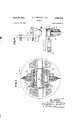
Referring now to the drawings, the grinder comprises a mounting bracket 10 to which is fixedly secured a pulley bracket 12. The pulley bracket is provided with a bearing 14 rotatably securing a driving sheave l6 having a shaft portion 18 received in the hearing. The driving sheave 16 is associated with a sheave portion 19 adapted to be connected by a V-belt to a power source such as the sheave 20 which may be mounted on a motor shaft or the like. The bracket 16 is split as indicated at 21 and is provided with an enlarged opening 22 which receives the end portion of a tubular support bar 24. I
Adajcent the opposite end of the bar 24 there is provided a head 26 welded or otherwise secured to the end of the bar 24 and reinforced by a web portion 28. The head 26 includes a cylindrical mounting portion 29 which is received in the outer end of the tubular bar 24.
The head portion 26 is cut away as indicated at 30 to receive a grinding wheel 32 which as seen in Figure 3, is clamped against a shoulder 34 by a nut 36. The shoulder 34 constitutes one side of a driven sheave 35, the other side of the sheave being formed by the portion 38. The sheave 35 and grinding wheel 32 are rotatable on bearings 40, the inner bearing race being supported on a cross shaft 42. As best seen in Figure 2, the mounting of the grinding wheel and driven sheave 3-5, 33 comprises V-shaped notches 44 formed at the end of the head 26, the shaft 42 having its end portions received in the notches and being provided with a flattened portion 46 adjacent each end thereof engageable by a clamp 48 held in position by clamping screws 50.
From the foregoing it will be observed that the axis of the grinding wheel 32 and driven sheave 35 is fixed with reference to the longitudinal axis of the bar 24 and is inclined obliquely thereto at an angle complementary to the helical angle of the broach teeth which are to be ground in the broach. In Figure 1 it will also be observed that the driving sheave 16 is mounted in a position displaced laterally from the longitudinal axis of the bar 24 and with its axis inclined thereto in the same direction as the angle of inclination of the grinding wheel and driven sheave. It will of course be understood that the amount by which the sheave 16 is offset is determined by the size of the opening in the broach to be ground. The driving shaft 18 is offset as much as clearance conditions permit. It will further be understood that the specific angle of inclination of the driving sheath 16 is intermediate the angle of inclination of the grinding wheel. The exact inclination of the axis of the driving sheath in is determined by the amount which it may be offset from the longitudinal axis or center line of the bar 24, the arrangement being such that a belt 52 connecting the sheaves 16 and 35 extends perpendicular to the axis of the driving sheave 15.
The driven sheave 35 is arranged so that its side portions 34 and 38 conform as nearly as possible with the V-belt 52. Experience has indicated that with the parts as illustrated in Figure 1, the grinding wheel 32 operates perfectly satisfactorily.
The present invention as so far described relates to a grinder for the purpose of producing helical teeth at the interior of a tubular broach. The elongated rigid support bar which supports the grinding wheel in the interior of the tubular broach is dimensioned so that it is receivable in the interior of the broach only with its longitudinal axis substantially parallel to the axis of the breach. Accordingly, if the grinder is intended to produce a breach for broaching external gear teeth having a five degree helix angle, it Will be appreciated that the axis of the grinding wheel is inclined to the longitudinal axis of the support bar by an angle complementary to the helix angle to be formed on the broach teeth, and hence, to be produced on a work gear broached by the broach. In some cases the required angularity of the grinding wheel, the length of the broach, and its internal diameter may be such as to preclude satisfactory driving connection between a V-belt from the sheave 16 to the sheave 35. In such case it is possible to use a grinder which includes a transfer such as shown in Figures 5:8. As seen in these figures, there is provided one or more transfer shafts 54 having driven sheaves 55 and driving sheaves 56 afiixed to opposite ends thereof. A first V-bel-t 58 is adapted to engage a driven sheave and thereby to drive the associated driving sheave. Where a plurality of transfer shafts 54 are provided, as is indicated in Figure 5, adjacent sheaves thereof are interconnected by V-belts 59. The shaft 54 nearest to the grinding wheel 32 is connected to a sheave 60 by a belt 62. The sheave 6t) and the grinding wheel 32 are fixed to a shaft 64 supported for rotation in suitable bearings as indicated at 66, the bearing assembly being clamped to the end of the head 68 by straps '70 and assembly screws 72.
It will of course be appreciated that appropriate provision must be made for clearance of the belt 62 and an appropriate depression or channel 74 is provided in the head and in the end portion of the tubular support 24.
The shafts 54 and associated sheaves 55 and 56 may conveniently be mounted on a web or flange 75 as best illustrated in Figures 6 and 7. The ends of the shaft 54 are supported in suitable bearing mounts 78 attached to the flange 76 by screws or the like as indicated at 30. Openings 82 are provided so that the sheaves 55 and 56 extend through the openings, portions thereof being spaced both above and below the platform or flange 76 as most clearly illustrated in Figure 7. Thus, the sheaves 55 and 56 serve to guide the belts 58, 59 and 62 through the openings so that portions of the belts lie at opposite sides of the platform 76.
The drawings and the foregoing specification constitute a description of the improved grinder in such full, clear, concise and exact terms as to enable any person skilled in the art to practice the invention, the scope of which is indicated by the appended claims.
What we claim as our invention is:
1. A grinder for grinding helical teeth at the interior of elongated tubular broaches, comprising an elongated rigid bar dimensioned to be received in the interior of the tubular broach only when positioned substantially parallel thereto, a rotatable grinding wheel carried in fixed position at one end of said bar, a driven sheave fixed to said wheel for rotation therewith, said wheel having its axis inclined obliquely to the longitudinal axis of said bar at an angle complementary to the required helix angle of the teeth to be ground on said broach, a drive sheave on said bar spaced from said one end thereof by the amount 4 which said wheel is required to move into the broach, the axis of said drive sheave being inclined at an angle to the longitudinal axis of said bar in the same direction as the inclination of the axis of said wheel, a belt connecting said sheaves, and power means for driving said drive sheave.
2. A grinder as defined in claim 1 in which the axes of said drive sheave and wheel are inclined at different angles to the longitudinal axis of said bar.
3. A grinder for grinding helical teeth at the interior of elongated tubular broaches, comprising an elongated rigid bar dimensioned to be received in the interior of the tubular broach only when positioned substantially parallel thereto, a rotatable grinding wheel carried in fixed position at one end of said bar, a driven sheave fixed to said wheel for rotation therewith, said wheel having its axis inclined obliquely to the longitudinal axis of said bar at an angle complementary to the required helix angle of the teeth to be ground on said broach, a drive sheave on said bar spaced from said one end thereof by the amount which said wheel is required to move into the broach, the axis of said drive sheave being inclined at an angle to the longitudinal axis of said bar in the same direction as the inclination of the axis of said wheel, said drive sheave being offset laterally from said bar to the extent permitted by clearance consideration with the broach, a belt connecting said sheaves, and power means for driving said drive sheave.
4. A grinder for grinding helical teeth at the interior of elongated tubular breaches, comprising an elongated rigid bar dimensioned to be received in the interior of the tubular broach only when positioned substantially parallel thereto, a rotatable grinding wheel carried in fixed position at one end of said bar, a driven sheave fixed .to said wheel for rotation therewith, said wheel having its axis inclined obliquely to the longitudinal axis of said bar at an angle complementary to the required helix angle of the teeth to be ground on said broach, a drive sheave on said bar spaced from said one end thereof by the amount which said wheel is required to move into the broach, the axis of said drive sheave being inclined at an angle to the longitudinal axis of said bar in the same direction as the inclination of the axis of said wheel, a transfer shaft carried by said bar intermediate said drive sheave and said driven sheave, said transfer shaft being inclined to the longitudinal axis of said bar in the same direction as the inclination of the axes of said sheaves, transfer sheaves fixed to opposite ends of said transfer shaft, a belt connecting said drive sheave to one of said transfer sheaves, a second belt connecting the other of said transfer sheaves to said driven sheave, and power means for driving said drive sheave.
References Cited in the file of this patent UNITED STATES PATENTS 985,412 Hattersley et al Feb. 28, 1911 1,328,953 Garrison Ian. 27, 1920 2,319,582 Carroll May 18, 1943 2,808,686 Haack Oct. 8, 1957
Priority Applications (1)
| Application Number | Priority Date | Filing Date | Title |
|---|---|---|---|
| US775883A US2981035A (en) | 1958-11-24 | 1958-11-24 | Grinder |
Applications Claiming Priority (1)
| Application Number | Priority Date | Filing Date | Title |
|---|---|---|---|
| US775883A US2981035A (en) | 1958-11-24 | 1958-11-24 | Grinder |
Publications (1)
| Publication Number | Publication Date |
|---|---|
| US2981035A true US2981035A (en) | 1961-04-25 |
Family
ID=25105832
Family Applications (1)
| Application Number | Title | Priority Date | Filing Date |
|---|---|---|---|
| US775883A Expired - Lifetime US2981035A (en) | 1958-11-24 | 1958-11-24 | Grinder |
Country Status (1)
| Country | Link |
|---|---|
| US (1) | US2981035A (en) |
Cited By (11)
| Publication number | Priority date | Publication date | Assignee | Title |
|---|---|---|---|---|
| FR2332100A1 (en) * | 1975-11-21 | 1977-06-17 | Kapp Et Co Werkzeugmaschinenfa | DEVICE FOR RECTIFYING INTERIOR PROFILES PARALLEL TO THE AXIS OF A PART |
| US4754574A (en) * | 1986-10-30 | 1988-07-05 | The Warner & Swasey Company | Apparatus for grinding a workpiece |
| US4858387A (en) * | 1986-10-30 | 1989-08-22 | Clough Arthur H | Apparatus for grinding a workpiece |
| US20040267373A1 (en) * | 2003-06-25 | 2004-12-30 | Dwyer Kimberly Ann | Assembly tool for modular implants and associated method |
| US20050033444A1 (en) * | 2003-06-25 | 2005-02-10 | Jones Michael C. | Assembly tool for modular implants and associated method |
| US8518050B2 (en) | 2007-10-31 | 2013-08-27 | DePuy Synthes Products, LLC | Modular taper assembly device |
| US8998919B2 (en) | 2003-06-25 | 2015-04-07 | DePuy Synthes Products, LLC | Assembly tool for modular implants, kit and associated method |
| US9095452B2 (en) | 2010-09-01 | 2015-08-04 | DePuy Synthes Products, Inc. | Disassembly tool |
| US9101495B2 (en) | 2010-06-15 | 2015-08-11 | DePuy Synthes Products, Inc. | Spiral assembly tool |
| US9504578B2 (en) | 2011-04-06 | 2016-11-29 | Depuy Synthes Products, Inc | Revision hip prosthesis having an implantable distal stem component |
| US9717545B2 (en) | 2007-10-30 | 2017-08-01 | DePuy Synthes Products, Inc. | Taper disengagement tool |
Citations (4)
| Publication number | Priority date | Publication date | Assignee | Title |
|---|---|---|---|---|
| US985412A (en) * | 1910-08-01 | 1911-02-28 | Victor Safe & Lock Co | Method of producing screw-threads by grinding. |
| US1328953A (en) * | 1917-06-04 | 1920-01-27 | Garrison Orlando | Grinding-machine |
| US2319582A (en) * | 1941-07-07 | 1943-05-18 | Guy B Carroll | Internal keyway grinder |
| US2808686A (en) * | 1956-01-09 | 1957-10-08 | Frank W Haack | Adjustable arbor and clamp-standard for power-driven tools |
-
1958
- 1958-11-24 US US775883A patent/US2981035A/en not_active Expired - Lifetime
Patent Citations (4)
| Publication number | Priority date | Publication date | Assignee | Title |
|---|---|---|---|---|
| US985412A (en) * | 1910-08-01 | 1911-02-28 | Victor Safe & Lock Co | Method of producing screw-threads by grinding. |
| US1328953A (en) * | 1917-06-04 | 1920-01-27 | Garrison Orlando | Grinding-machine |
| US2319582A (en) * | 1941-07-07 | 1943-05-18 | Guy B Carroll | Internal keyway grinder |
| US2808686A (en) * | 1956-01-09 | 1957-10-08 | Frank W Haack | Adjustable arbor and clamp-standard for power-driven tools |
Cited By (31)
| Publication number | Priority date | Publication date | Assignee | Title |
|---|---|---|---|---|
| FR2332100A1 (en) * | 1975-11-21 | 1977-06-17 | Kapp Et Co Werkzeugmaschinenfa | DEVICE FOR RECTIFYING INTERIOR PROFILES PARALLEL TO THE AXIS OF A PART |
| US4754574A (en) * | 1986-10-30 | 1988-07-05 | The Warner & Swasey Company | Apparatus for grinding a workpiece |
| US4858387A (en) * | 1986-10-30 | 1989-08-22 | Clough Arthur H | Apparatus for grinding a workpiece |
| US20090307887A1 (en) * | 2003-06-25 | 2009-12-17 | Depuy Products, Inc. | Assembly tool for modular implants and associated method |
| US20050033444A1 (en) * | 2003-06-25 | 2005-02-10 | Jones Michael C. | Assembly tool for modular implants and associated method |
| US7297166B2 (en) | 2003-06-25 | 2007-11-20 | Depuy Products, Inc. | Assembly tool for modular implants and associated method |
| US20080091212A1 (en) * | 2003-06-25 | 2008-04-17 | Depuy Products, Inc. | Assembly tool for modular implants and associated method |
| US7582092B2 (en) | 2003-06-25 | 2009-09-01 | Depuy Products, Inc. | Assembly tool for modular implants and associated method |
| US9381097B2 (en) | 2003-06-25 | 2016-07-05 | DePuy Synthes Products, Inc. | Assembly tool for modular implants, kit and associated method |
| US8419799B2 (en) | 2003-06-25 | 2013-04-16 | Depuy Products, Inc. | Assembly tool for modular implants and associated method |
| US8685036B2 (en) | 2003-06-25 | 2014-04-01 | Michael C. Jones | Assembly tool for modular implants and associated method |
| US8998919B2 (en) | 2003-06-25 | 2015-04-07 | DePuy Synthes Products, LLC | Assembly tool for modular implants, kit and associated method |
| US20040267373A1 (en) * | 2003-06-25 | 2004-12-30 | Dwyer Kimberly Ann | Assembly tool for modular implants and associated method |
| US9717545B2 (en) | 2007-10-30 | 2017-08-01 | DePuy Synthes Products, Inc. | Taper disengagement tool |
| US8518050B2 (en) | 2007-10-31 | 2013-08-27 | DePuy Synthes Products, LLC | Modular taper assembly device |
| US9119601B2 (en) | 2007-10-31 | 2015-09-01 | DePuy Synthes Products, Inc. | Modular taper assembly device |
| US9101495B2 (en) | 2010-06-15 | 2015-08-11 | DePuy Synthes Products, Inc. | Spiral assembly tool |
| US10166118B2 (en) | 2010-06-15 | 2019-01-01 | DePuy Synthes Products, Inc. | Spiral assembly tool |
| US9867720B2 (en) | 2010-09-01 | 2018-01-16 | DePuy Synthes Products, Inc. | Disassembly tool |
| US10292837B2 (en) | 2010-09-01 | 2019-05-21 | Depuy Synthes Products Inc. | Disassembly tool |
| US9095452B2 (en) | 2010-09-01 | 2015-08-04 | DePuy Synthes Products, Inc. | Disassembly tool |
| US9737405B2 (en) | 2011-04-06 | 2017-08-22 | DePuy Synthes Products, Inc. | Orthopaedic surgical procedure for implanting a revision hip prosthesis |
| US9949833B2 (en) | 2011-04-06 | 2018-04-24 | DePuy Synthes Products, Inc. | Finishing RASP and orthopaedic surgical procedure for using the same to implant a revision hip prosthesis |
| US10064725B2 (en) | 2011-04-06 | 2018-09-04 | DePuy Synthes Products, Inc. | Distal reamer for use during an orthopaedic surgical procedure to implant a revision hip prosthesis |
| US9504578B2 (en) | 2011-04-06 | 2016-11-29 | Depuy Synthes Products, Inc | Revision hip prosthesis having an implantable distal stem component |
| US10226345B2 (en) | 2011-04-06 | 2019-03-12 | DePuy Synthes Products, Inc. | Version-replicating instrument and orthopaedic surgical procedure for using the same to implant a revision hip prosthesis |
| US9597188B2 (en) | 2011-04-06 | 2017-03-21 | DePuy Synthes Products, Inc. | Version-replicating instrument and orthopaedic surgical procedure for using the same to implant a revision hip prosthesis |
| US10603173B2 (en) | 2011-04-06 | 2020-03-31 | DePuy Synthes Products, Inc. | Orthopaedic surgical procedure for implanting a revision hip prosthesis |
| US10772730B2 (en) | 2011-04-06 | 2020-09-15 | DePuy Synthes Products, Inc. | Finishing rasp and orthopaedic surgical procedure for using the same to implant a revision hip prosthesis |
| US10888427B2 (en) | 2011-04-06 | 2021-01-12 | DePuy Synthes Products, Inc. | Distal reamer for use during an orthopaedic surgical procedure to implant a revision hip prosthesis |
| US10925739B2 (en) | 2011-04-06 | 2021-02-23 | DePuy Synthes Products, Inc. | Version-replicating instrument and orthopaedic surgical procedure for using the same to implant a revision hip prosthesis |
Similar Documents
| Publication | Publication Date | Title |
|---|---|---|
| US2981035A (en) | Grinder | |
| US4739669A (en) | Driving apparatus for industrial robot | |
| US3513888A (en) | Portable power driven circular saw | |
| US3519037A (en) | Saw chain driving apparatus | |
| US5771583A (en) | Cutter blade support for a hedge trimmer | |
| US3202189A (en) | Saw apparatus | |
| US3024687A (en) | Rotary cut-off machines | |
| US2412705A (en) | Portable saw | |
| US4972564A (en) | Apparatus for correcting surface imperfections on a surface of gear tooth | |
| US3299778A (en) | Circular saws | |
| US2925104A (en) | Combination chain-and-circular-saw portable power saw unit | |
| US4067368A (en) | Cabin log shaper | |
| US4211371A (en) | Device for the balanced fixing and mounting of blades in machines provided to cut, crush and hash | |
| GB1279807A (en) | Apparatus for tapering ends of laminated plastic pipe | |
| US2396860A (en) | Speed reducing unit | |
| US6158320A (en) | Saw arbor with splined mandrel and mating, timed internally and externally splined saw blade mounting sleeve | |
| US2342459A (en) | Power saw | |
| US4204320A (en) | Sprocket shaft stay | |
| US6244143B1 (en) | Lathe | |
| US2994989A (en) | Gear finishing machine employing master gears | |
| US2795251A (en) | Coping saw | |
| US4327613A (en) | Apparatus for machining axle shafts | |
| DE3505041C2 (en) | ||
| GB2095168A (en) | Circular saw blade having a ring shaped profile | |
| GB1578979A (en) | Device for the balanced fixing and mounting of blades in machines provided to cut crush hash and reduce to soft paste food products and similar |