US2981369A - Vortical whirl separator - Google Patents
Vortical whirl separator Download PDFInfo
- Publication number
- US2981369A US2981369A US257702A US25770251A US2981369A US 2981369 A US2981369 A US 2981369A US 257702 A US257702 A US 257702A US 25770251 A US25770251 A US 25770251A US 2981369 A US2981369 A US 2981369A
- Authority
- US
- United States
- Prior art keywords
- separator
- chamber
- discharge
- ash
- blowdown
- Prior art date
- Legal status (The legal status is an assumption and is not a legal conclusion. Google has not performed a legal analysis and makes no representation as to the accuracy of the status listed.)
- Expired - Lifetime
Links
Images


Classifications
-
- B—PERFORMING OPERATIONS; TRANSPORTING
- B04—CENTRIFUGAL APPARATUS OR MACHINES FOR CARRYING-OUT PHYSICAL OR CHEMICAL PROCESSES
- B04C—APPARATUS USING FREE VORTEX FLOW, e.g. CYCLONES
- B04C5/00—Apparatus in which the axial direction of the vortex is reversed
- B04C5/08—Vortex chamber constructions
- B04C5/103—Bodies or members, e.g. bulkheads, guides, in the vortex chamber
Definitions
- This invention relates to reverse flow vortical whirl separators, and, more particularly, to relatively small, pressure-sustaining bottomed, cylindrical units adapted for use in ash removal equipment of pressurized combustion systems using powdered coal, such as are used in generating electric locomotives powered by coal-tired gas turbine power plants.
- Such locomotives and power plants are shown and claimed in Patent No. 2,533,866, issued Dec. l2, 1950 to John I. Yellott, for Generating Electric Locomotive With Coal Fired Gas Turbine.
- the invention also comprehends improved methods of separating particulate material from entraining gasiforrn iluids, and continuous removal of the particulate material, as separated, in -blowdown streams comprising minute fractional portions of the gasiform lluid.
- the length of the primary separator section or barrel should be twice its diameter; the discharge or secondary collection chamber should lbe one-halt the length of the barrel; the breather hole in the axially apertured diaphragm or razor plate should be about one-tenth the diameter of the tube; While the diameter of the blowdown line should approximate one-half the diameter of the breather hole.
- a l0-inch diameter cylindrical tube should have a 20-inch barrel, a lll-inch long.
- the spinner vanes should have an outlet angle of 30, and be contained in a collar or annulus 5.75inch wide.
- the breather hole should have no collars.
- full-size, cylindrical, vortical whirl separators were made up of transparent plastic, and fully instrumented to give accurate readings of airflow and pressure at all points in the device, as well as permitting visual study of the conditions of flow of the solids-bearing air streams.
- the use of such a device quickly established a number of interesting facts.
- the primary separation taking place in the barrel oi the separator established a sheath stream of particle-laden gas spiraling through the skimmer blades of the razor plate into the secondary separator, and a reversely iiowing cleaned gas stream discharging from the core of the barrel through the cleaned gas outlet pipe.
- the conditions observed in the discharge chamber or secondary separator are much more complex.
- the major portion of the coarse solids separated out in the primary separator and discharged into the secondary separator is immediately removed in the blowdown line.
- the unseparated line ash in the primary air stream is transported, at the bottom of the barrel section, to the axis of the barrel immediately above the breather hole in the diaphragm.
- the axial column of particle-containing gas also acts as a solid grinding or abrading member, with the result that the axis of the base of the secondary chamber may be vigorously scoured and abraded.
- Feifel has described this axial air column or vortex as simulating the eye of a tornado.
- the 4reason for the grinding action being established in accordance with the present invention, it was found that its effects could be mitigated by providing vortex rellectors, wear members, and other inserts of various types in the center of the base of the secondary separator, vall as will be described more in detail hereinafter.
- This flow is that of a at, helical, down-flowing sheath stream hugging the wall of the secondary chamber, and then spiralling inward, at the bottom of the pot, to the axis of the chamber, in a tightening spiral, thence axially upward, as a vortex, in a tight, helical core stream, to expand, in part, -radially outward across the bottom of the razor plate and return to join the descending sheath stream hugging the wall of the secondary chamber.
- tertiary separators with individual blowdown lines, may be incorporated inthe novel separators herein, and with marked economies, as well as improved eiciency in ne ash (plus 10 micron) removal.
- Figure 1 is a schematic showingof a coal-burning gas turbine power plant with an ash separator assembly
- Fig. 2 is a schematic showing of the combustor and ash separating elements of the power plant of Fig. 1, with the combustor, burner, and invididual vortical whirl ash separators shown in elevation;
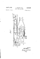
- Fig. 3 is an elevation, partly in broken section, of a pressure-sustaining, reverse ow vortical whirl separator having a spinner inlet, an axial cleaned air return pipe, a pimary separator chamber, and a secondary separator or discharge chamber with a tangential blowdown line, together with an intermediate diaphragm incorporating an axial breather hole and peripheral skimmer blades;
- Fig. 3a is a graph illustrating the relative collection efficiency of separators of the type illustrated in Fig. 3, in which the spinner blades are respectively set at exit angles of 30 and 45;
- Fig. 4 is a view similar to Fig. 3 showing double tangential inlets
- Fig. 5 is a view similar to Fig. 3 showing a scroll inlet
- Fig. 6 is a fragmentary vertical section of a discharge or secondary separator chamber with a tangential blowdown line and an axial fogging jet;
- Fig. 7 is a fragmentary elevation, partly in broken section, of the base of a primary separator chamber and a subjoined discharge or secondary separator chamber,'
- Fig. 8 is a fragmentary section of a diaphragm showing the detail of a skimmer blade
- Fig. 9 is a vertical section through a discharge or secondary separator chamber showing the air-flow and an axial conical wear member
- Fig. 10 is a view similar to Fig. 9 showing a cubical' wear member
- Fig. 11 is a view similar to Fig. 9 showing a wear plate welded on the base of the separator;
- Fig. 12 is a view similar to Figs. 9-11, with the axial wear members replaced by a tertiary axial separator chamber with a separate blowdown line;
- Figs. 13-16 are elevations of modied axial wearing elements for discharge or secondary separator chambers
- Fig. 17 is yan elevation, partly in broken section, of a Vvortical whirl separator with a double-walled peripheral discharge or secondary separator chamber;
- a coal-burning, gas turbinepowered, generating electric power plant particularly adapted for high pressure motive uid generation and use in restricted spaces, such ⁇ as obtain in generating electric locomotives.
- the system comprises generally a source of combustive air-borne fluidized coal 1, a coal splitter 2, a plurality of combustors, designated generally by the numeral 3, and feed lines 4 from the coal splitter to the combustors.
- Motive iluid is discharged from the combustors to ash separator 5 through ducts 6.
- Cleaned motive fluid is then delivered to the turbine 7 through expansion ducts 8, and the expanded gas from the turbine vents to the exhaust 9, which mounts a regenerator, indicated generally by the numeral 10.
- a main air compressor 11 is driven by the turbine, and delivers air through duct 12 to the regenerator, whence the heated air is fed to the combustors 3 through expansion ducts 13.
- the turbine shaft is coupled, in any suitable manner, to the power unit comprising D.C. traction generators 14, and auxiliary generators 15.
- the combustor 3 is seen to comprise a housing, a cold wall combustion chamber 20, a combination burner 21 having a coal-air feed line 4, and oil inlet and outlet lines 22, 23.
- The-burner is more specifically described and claimed in the companion application of Paul, M. Rotzler, Ser. No. 257,079, tiled U November I9, l95l,'now Patent No. 2,858,779, for
- ⁇ Cooling air from duct 13 flows over the outer and inner walls of the combustor chamber and' mixes with the hot combustion gases, the resulting ash-bearing motive iluid being discharged through apical louver separator 24 and duct 6 to the ily Iash separator assembly 5.
- the apical separator has an axial discharge line 25 to a coarse ash reducer and vortical whirl'separator, designated generally by the numeral 26, land more particularly disclosed and claimed in the Patent No. 2,652,792, of Sept. 22, 1953, issued to John I. Yellott, for Pressurized Combustion and Ash Removal System for Coal-Fired Gas Turbine Power Plant.
- ⁇ Cleaned gas from the separator is returned to the motive fluid stream through goose neck 27.
- An air jet is supplied by air line 28, and a blowdown line '29 serves to remove the reduced ash and uncombusted, quenched solids from the separator 26.
- the tine ash-bearing motive fluid is delivered to the ash separator assembly 5, wherein the ash is removed by passage through a battery of vortical whirl separator tubes', severally designated by the numeral 30, the cleaned motive iluid discharging to turbine 7 through duct 8.
- the individual vortical whirl separator tubes 30, as shown more in detail in Fig. 3, have barrel sections 31 mounting reverse flow axial cleaned air discharge tubes 32. Secondary separa-tion or discharge chambers 33 are secured to the bases of the barrel sections, diaphragm or razor plates ⁇ 40 being secured therebetween.
- the spinner type inlet separators herein have a plurality of deilector vanes 37 mounted on an annulus 38 which is fit-ted over the axial cleaned air discharge tube 32, and maintains the vanes 37 in place in the mouth of barrel sections 31. Usually the vanes are mounted to present an exit or discharge angle of 45.
- Afeature of the present invention is the discovery that the collection eiciency of the tubes is markedly increased by changing the ex-it angle to 30, as graphically shown in the diagram of Fig. V3a.
- the barrels 31 and discharge chambers 3'3 may be flanged, Ias indicated -generally at 39, to receive the razor plates di). These members have a central aperture 41, and a plurality of peripheral, upstruck blades or skimmers 42, defining discharge apertures 43 leading from the primary separation chamber in barrel 31 to the secondary separation or discharge chamber '33.
- the blades are preferably sharpened, and may have any suitable shape, such as spoon or scoop, and can be oriented in any manner found desirable to effect the maximum separation of particulate material from the primary gasiform fluid stream which is projected against the skimmer plate as a helically advancing sheath stream in contact with the inner wall of the barrel or primary separator chamber.
- the blades 42 are usually two or four in number, and no signicant different in results is observable between them.
- rlhe pneumatic blowdown lines 34 as shown, are tangential to .the Walls of the chambers 33 and at the base thereof. Because of the tight vortex action of the secondary cleaned air, there is an appreciable erosion or abrasion of the bases of the chambers 33, lat the axes thereof, and wear members, such ⁇ as conical wear member 44, may be mounted at such axes to eliminate or mitigate this condition. While the invention comprehends the use of fixed wear members, it will be understood that spinning or rotatable members may be used without departing from the spirit and scope of the invention.
- a desideratum in theoperation of the improved separators of the type herein considered is the imparting of a relatively flat helical ow to the incoming dust or solids-laden air or gas.
- the separator of Fig. 4 has a closed barrel 50 mounting the usual axial cleaned air reverse flow discharge pipe 32.
- a razor plate 40 and secondary separator or discharge chamber 33 are subjoined in the usual manner.
- balanced flow of inlet gases is secured by providing a pair of opposed, tangential inlet ducts 51, 52 at the top of the barrel section.
- the barrel secltion 53 is provided with a scroll-shaped closed top 54 having a single tangential inlet pipe 55 at its uppermost section.
- FIG. 7 Adverting to Fig. 7, there is shown an axially apertured diaphragm having but two :sharpened skimmer or razor blades 42. These blades, las shown indetail in Fig. 8, are arranged atan angle of substantially 30 to the horizontal, to accord with the delector vanes 37 at the separator inlet, described hereinabove.
- abrasion guards of Figs. 3-5, and 7 are conoidal in shape, and are designated generally bythe numeral 44.
- the guards 44a and 44b of Figs. 13 and 14, respectively, have axial cross-sections approximating equilateral triangles having concave or inwardly bowed sides, as opposed to the convex sides of the axial crosssection of guards 44.
- the ⁇ guard 44C, illustrated in Fig. l5 is ⁇ anvil shaped, with a parabolic b'owl formed in its upper surface.
- the guard 44d, illustrated in Fig. 16, is also anvil shaped, but has a flat upper surface.
- a metallic wear member 44]c is welded in place in the bottom of the secondary separator33, while in the separator of Fig. 12, a wear plate ⁇ 44g is tted in the bottom of tertiary separator 33h formed in the bottom of secondary separator 33a.
- a separate preumatic blowdown line 34a is provided for the tertiary separator.
- the discharge chamber 33 is provided with a concentric inner wall member, 33a defining an annular chamber 33b therewith. Access to this chamber is had through the skimmer blade openings in the diaphragm 40.
- the inner wall 33a is provided with a plurality of radial openings 33e at the bottom. These openings provide access between the annular chamber 3311 and the inner chamber 33d formed by inner wall 33a, the diaphragm plate and the bottom of the secondary separator.
- the openings 33e provide multiple entrants to the inner chamber 33d, and the breather hole 41 forms a single, restricted axial outlet.
- the coarse particles delivered by the vortical whirl of the primary separator chamber through the skimmer blade apertures into annular chamber 33b ' will be whirled around in the chamber and reduced in size, so that the medium size particles will be asported and pneumatically discharged in the blowndown stream through blowndown line 34, and the finer particles will be drawn in through openings 33e and discharged through the axial breather hole 41.
- the particle size of discrete material drawn into chamber 33d by the axial gas current discharging through axial discharge opening 41 can be controlled, as may be desired.
- the incorporation of the pneumatic discharge blowdown principle vin the novel reverse ow vortical whirl separators herein permits the handling of particle-containing, high pressure and high temperature (1500 F.), gas streams, and the removal of the contained particles from the separators by utilizing from 1 to 10% of the gas stream as a blowdown stream, thereby eliminating mechanical ash removing equipment from the system.
- the vortical whirl separators herein are capable of functioning as self-sustaining pressure vessels, thereby permitting their use in locomotive power plants, where appreciable and important reductions in size and Weight of ash removal equipment can be effected, all as more particularly set out and claimed in our companion application Ser. No. 330,077, tiled Ian. 7, 1953, now Patent No. 2,911,065, for Coal-Burning Gas Turbine Power Plants Incorporating Novel Self-Supporting, and Pressure-Sustaining Vortical Whirl Separators together with Improved Ash Quenching and Blowdown Means.
- a reverse ow vortical whirl separator comprising a flat-bottomed, cylindrical casing having an inlet for particle-laden gasiform iiuid and an axial outlet for cleaned gasiform iiuid at the same end, together with an axially apertured diaphragm skimmer plate at the other end; a discharge or secondary separator chamber in both peripheral and axial fluid communication with the casing through said diaphragm; a tangential blowdown line at the base of the secondary separator; and an abrasion guard at the axis of said base.
Landscapes
- Cyclones (AREA)
- Separating Particles In Gases By Inertia (AREA)
Description
April 25, 1961 J. YELLoTT ET AL VORTICAL WHIRL sEPARAToR 5 Sheets-Sheet 1 Filed Nov. 23 1951 INVENTORJ' JOHN yfaorr P575@ A. ,imams y BY MQW April 25, 1961 J. l. YELLOTT ET AL VORTICAL WHIRL SEPARATOR 5 Sheets-Sheet 2 Filed NOV. 25 1951 April 25, 1961 J. l. YELLOTT ET AL 2,981,369 voRTIcAL wHIRL sEPARAToR Filed Nov. 23, 1951 5 Sheets-Sheet 5 IN VEN TORS JOHN VL07'7' April 25, 1961 1. l. YELLOTT ET AL 2,981,369
voRTIcAL WHIRL SEPARATOR Filed Nov. 25, 1951 5 Sheets-Sheet 4 S g; :Taj Fw- April 25, 1961 J. YELLOTT ET AL 2,981,369
VORTICAL WHIRL SEPARATOR 5 Sheets-Sheet 5 Filed NOV. 25, 1951 v,bottom of the discharge chamber.
l VORTICAL WHIRL SEPARATOR John I. Yellott, New York, N.Y., and Peter R. Broadley, Elizabeth, NJ., assignors to Bituminous Coal Research, Inc., Washington, D.C., a corporation vof Delaware Filed Nov. 23, 1951, Ser. No. 257,702
1 Claim. (Cl. 18S- 85) This invention relates to reverse flow vortical whirl separators, and, more particularly, to relatively small, pressure-sustaining bottomed, cylindrical units adapted for use in ash removal equipment of pressurized combustion systems using powdered coal, such as are used in generating electric locomotives powered by coal-tired gas turbine power plants. Such locomotives and power plants are shown and claimed in Patent No. 2,533,866, issued Dec. l2, 1950 to John I. Yellott, for Generating Electric Locomotive With Coal Fired Gas Turbine. The invention also comprehends improved methods of separating particulate material from entraining gasiforrn iluids, and continuous removal of the particulate material, as separated, in -blowdown streams comprising minute fractional portions of the gasiform lluid.
Work on ash removal problems, in connection With the operation of generating electric locomotives of the type disclosed in the above-identified Yellot patent, shows that ash particles as small as 325 mesh (42 microns) are extremely erosive to turbine blading, and particularly when carried in l300 F., turbine motive fluid. Continuing research shows that it is necessary to remove virtually all of the plus 20 micron ash particles in order to reduce turbine blade erosion to an acceptable amount. The best known way to separate particles in the range from l to 40 microns in diameter from high temperature air is by the use of relatively small, reverse ow vortical whirl separators. These tubes operate well alone, but parallel operation of 2() to 30 tubes in a battery is yfrequently unsatisfactory. Difculty is often experienced in getting the collected ash out of the tubes, particularly when head room restrictions are as severe as on a locomotive.
, lt has now lbeen found that the problem of removal of plus l0 micron ash particles from gas turbine motive fluid (l300 F.), and at air-How rates of 600 to 1600 cu.
it. per min. per tube, can be satisfactorily solved Aby using batteries of relatively small, reverse ilow vortical whirl, cylindrical separators having individual discharge chambers wi-th small tangential blowdown lines, the separators being divided into two parts vby an axially apertured diaphragm with peripheral skimmer blades. U.S. Patent No. 769,808 (1904), disclosed a diaphragm with a radial slot at the periphery, while Feifel of Vienna discussed the function of such a-separator with an axially apertured `diaphragm having a `single radial peripheral slot. In no .case have the prior art workers disclosed a device having peripheral skimmer blades in the diaphragm, nor tangential blowdown lines for the discharge sections, and the majority showed only conventional discharge hoppers. Furthermore, the prior art is silent on the question of Vhigh temperature operation.
,ln addi-tion, discovery has been made of the eiciency .of the combination of a discharge chamber, functioning as a secondary separator with a tangential blowdown line located at the intersection of the side wall and the at Optimum operating characteristics were Vfound asthe resultof establishing the lUnited States Patent `500 to 1100 cubic feet per minute (c.f.m.).
2,981,369 Patented Apr. 25, i961 proper dimensional ratios between the several parts of the device. Thus, the length of the primary separator section or barrel should be twice its diameter; the discharge or secondary collection chamber should lbe one-halt the length of the barrel; the breather hole in the axially apertured diaphragm or razor plate should be about one-tenth the diameter of the tube; While the diameter of the blowdown line should approximate one-half the diameter of the breather hole. Translated into actual structure, it is noted that a l0-inch diameter cylindrical tube should have a 20-inch barrel, a lll-inch long. discharge or secondary collection chamber, a 1-inch breather hole in the razor plate, skimmer blades 1.5 inches wide, and a blowdown pipe .75 inch inside diameter. The spinner vanes should have an outlet angle of 30, and be contained in a collar or annulus 5.75inch wide. The breather hole should have no collars. o i
Vertical whirl separator tubes having the dimensions listed immediately above are eminently practical, and give goed collection efficiency as the air ow is raised from additional increase results when the flow is raised to 1500 cizm. per tube, and this added protection to the turbine blades is worth while. The novel cylindrical vortical whirl separator herein is relatively insensitive to the amount of air discharged through the blowdown pipe. A 1.5% blowdown (22 c.f.m. per tube) gives good eciency at an airflow of 1500` c.f.m.
The mechanics of separation of particulate solids and duid droplets from entraining gaseous lluid streams, particularly at pressures of the order of 50-100 p.s.i. and airtlow speeds of 60G-2000 c.f.m., are not too well known, and the published articles on the subject have been more often conjectural than factual. 'This is particularly `true of small size, cylindrical vortical whirl separators having a spinning entrant stream with a rectilinear discharge of separated particles and a reversal of ow of the cieaned huid. By placing a razor plate having a central breather or return hole at the base of the barrel of a separator, so that discharge of skimmed-0H solids into a subjacent separator is permitted, the relatively tine undischarged particles are continuously recirculated in the secondary separator in a vortical stream.
in order to clarify the situation and arrive at a clear, factual knowledge ofthe factors controlling the situation, full-size, cylindrical, vortical whirl separators were made up of transparent plastic, and fully instrumented to give accurate readings of airflow and pressure at all points in the device, as well as permitting visual study of the conditions of flow of the solids-bearing air streams. The use of such a device quickly established a number of interesting facts. The primary separation taking place in the barrel oi the separator established a sheath stream of particle-laden gas spiraling through the skimmer blades of the razor plate into the secondary separator, and a reversely iiowing cleaned gas stream discharging from the core of the barrel through the cleaned gas outlet pipe.
The conditions observed in the discharge chamber or secondary separator are much more complex. The major portion of the coarse solids separated out in the primary separator and discharged into the secondary separator is immediately removed in the blowdown line. The unseparated line ash in the primary air stream is transported, at the bottom of the barrel section, to the axis of the barrel immediately above the breather hole in the diaphragm.
Here it meets the air issuing from the breather hole, which, expanding radially, returns the primary fine ash to the wall of the barrel where it again contacts the primary sheath stream, and the iine ash is agglomerated and asported with the coarse ash particles into the secondary separator. The second increment of ne ash, i.e., that portion which is entrainedV into the secondary separator, is recirculated A small therein. Visual observation of the secondary separator chamber establishes that the iine ash is carried, in a tightly spiraling air stream, toward the 4axis of the chamber, at which point is forms an ascending vorticalaxial column, from which the dust is thrown radially towards the wall of the chamber.Y
The axial column of particle-containing gas also acts as a solid grinding or abrading member, with the result that the axis of the base of the secondary chamber may be vigorously scoured and abraded. Feifel has described this axial air column or vortex as simulating the eye of a tornado. At any rate, the 4reason for the grinding action being established, in accordance with the present invention, it was found that its effects could be mitigated by providing vortex rellectors, wear members, and other inserts of various types in the center of the base of the secondary separator, vall as will be described more in detail hereinafter.
Considering the axial solids-bearing column further, it was found, by visual observation, that the reversely flowing vortically spinning, tight spiral, before issuing from the breather hole, projected the fine ash particles microns and above) radially into the descending helical sheath stream along the wall of the secondary separator, where the particles agglomerate with the coarser particles of the sheath stream; and are discharged and asported in the blowdown line. y Thus, the major line solids removal action of the novel, multipartite vortical whirl separators herein is found to lie in the toroidal flow of the secondary gas stream in the secondary separator chamber. This flow is that of a at, helical, down-flowing sheath stream hugging the wall of the secondary chamber, and then spiralling inward, at the bottom of the pot, to the axis of the chamber, in a tightening spiral, thence axially upward, as a vortex, in a tight, helical core stream, to expand, in part, -radially outward across the bottom of the razor plate and return to join the descending sheath stream hugging the wall of the secondary chamber. Further studies indicate that tertiary separators, with individual blowdown lines, may be incorporated inthe novel separators herein, and with marked economies, as well as improved eiciency in ne ash (plus 10 micron) removal.
It is, therefore, among the features of novelty and advantage of the present invention to provide novel vortical whirl separators, and methods of operating the same, for separating particulate material from entraining gasiform uids, and characterized by special blowdown lines for the pneumatic removal of the separated particulate material in blowdown streams comprising a minute fraction of the volume of the original gasiform fluids. Other features of novelty and advantage include such separators having primary and secondary separator chambers with axially apertured diaphragm skimmer plates therebetween having peripheral skimmer blades, and establishing both peripheral and axial fluid communication between the chambers, the secondary chamber discharging into a blowdown line. It is also a feature of novelty and advantage of the invention herein to provide separators of the type described wherein the dimensions of the several parts are interrelated, and the secondary chambers are provided with axial abrasion-resisting elements.
With these and other features of novelty and advantage in view, which may be incident to the improvements herein, the invention consists in the parts and combinations to be hereinafter set forth `and claimed, with the understanding that the several necessary elementscomprising the invention, may be varied in construction, proportions and arrangements, as well as in mode of operation, without departing from the spirit and scope of the appended claim.
In order to make the invention more clearly understood, there is shown in the accompanying drawings means for. carrying the same into practical eiect, without limiting the improvements in their useful application to the planation, have been made the subect of illustration.
In the drawings, like numerals refer to similar partsv throughout the several views, of which Figure 1 is a schematic showingof a coal-burning gas turbine power plant with an ash separator assembly;
Fig. 2 is a schematic showing of the combustor and ash separating elements of the power plant of Fig. 1, with the combustor, burner, and invididual vortical whirl ash separators shown in elevation;
Fig. 3 is an elevation, partly in broken section, of a pressure-sustaining, reverse ow vortical whirl separator having a spinner inlet, an axial cleaned air return pipe, a pimary separator chamber, and a secondary separator or discharge chamber with a tangential blowdown line, together with an intermediate diaphragm incorporating an axial breather hole and peripheral skimmer blades;
Fig. 3a is a graph illustrating the relative collection efficiency of separators of the type illustrated in Fig. 3, in which the spinner blades are respectively set at exit angles of 30 and 45;
Fig. 4 is a view similar to Fig. 3 showing double tangential inlets;
Fig. 5 is a view similar to Fig. 3 showing a scroll inlet;
Fig. 6 is a fragmentary vertical section of a discharge or secondary separator chamber with a tangential blowdown line and an axial fogging jet;
Fig. 7 is a fragmentary elevation, partly in broken section, of the base of a primary separator chamber and a subjoined discharge or secondary separator chamber,'
with the diaphragm having two skimmer blades;
Fig. 8 is a fragmentary section of a diaphragm showing the detail of a skimmer blade; Y
Fig. 9 is a vertical section through a discharge or secondary separator chamber showing the air-flow and an axial conical wear member;
Fig. 10 is a view similar to Fig. 9 showing a cubical' wear member;
Fig. 11 is a view similar to Fig. 9 showing a wear plate welded on the base of the separator;
Fig. 12 is a view similar to Figs. 9-11, with the axial wear members replaced by a tertiary axial separator chamber with a separate blowdown line;
Figs. 13-16 are elevations of modied axial wearing elements for discharge or secondary separator chambers;
Fig. 17 is yan elevation, partly in broken section, of a Vvortical whirl separator with a double-walled peripheral discharge or secondary separator chamber;
Turning now to the drawings, and more particularly to Fig. 1, there is shown a coal-burning, gas turbinepowered, generating electric power plant particularly adapted for high pressure motive uid generation and use in restricted spaces, such `as obtain in generating electric locomotives. The system, as shown, comprises generally a source of combustive air-borne fluidized coal 1, a coal splitter 2, a plurality of combustors, designated generally by the numeral 3, and feed lines 4 from the coal splitter to the combustors. Motive iluid is discharged from the combustors to ash separator 5 through ducts 6. Cleaned motive fluid is then delivered to the turbine 7 through expansion ducts 8, and the expanded gas from the turbine vents to the exhaust 9, which mounts a regenerator, indicated generally by the numeral 10. A main air compressor 11 is driven by the turbine, and delivers air through duct 12 to the regenerator, whence the heated air is fed to the combustors 3 through expansion ducts 13. The turbine shaft is coupled, in any suitable manner, to the power unit comprising D.C. traction generators 14, and auxiliary generators 15.
Referring to Fig. 2, the combustor 3 is seen to comprise a housing, a cold wall combustion chamber 20, a combination burner 21 having a coal-air feed line 4, and oil inlet and outlet lines 22, 23. The-burner is more specifically described and claimed in the companion application of Paul, M. Rotzler, Ser. No. 257,079, tiled U November I9, l95l,'now Patent No. 2,858,779, for
Powdered Coal Burner for Pressurized Combustors.
`Cooling air from duct 13 flows over the outer and inner walls of the combustor chamber and' mixes with the hot combustion gases, the resulting ash-bearing motive iluid being discharged through apical louver separator 24 and duct 6 to the ily Iash separator assembly 5. The apical separator has an axial discharge line 25 to a coarse ash reducer and vortical whirl'separator, designated generally by the numeral 26, land more particularly disclosed and claimed in the Patent No. 2,652,792, of Sept. 22, 1953, issued to John I. Yellott, for Pressurized Combustion and Ash Removal System for Coal-Fired Gas Turbine Power Plant.
`Cleaned gas from the separator is returned to the motive fluid stream through goose neck 27. An air jet is supplied by air line 28, and a blowdown line '29 serves to remove the reduced ash and uncombusted, quenched solids from the separator 26.
The tine ash-bearing motive fluid is delivered to the ash separator assembly 5, wherein the ash is removed by passage through a battery of vortical whirl separator tubes', severally designated by the numeral 30, the cleaned motive iluid discharging to turbine 7 through duct 8. The individual vortical whirl separator tubes 30, as shown more in detail in Fig. 3, have barrel sections 31 mounting reverse flow axial cleaned air discharge tubes 32. Secondary separa-tion or discharge chambers 33 are secured to the bases of the barrel sections, diaphragm or razor plates `40 being secured therebetween. The secondary chambers 33 `are provided with separate pneumatic discharge means for separated ash comprising blowdown lines 34 discharging to blowdown manifold 35, from whence the ash is pneumatically purged from the system through critical llow nozzle 36, whereby there is a uniform pressure maintained in the separators, with no blowback therebetween due to dilferential discharge pressures in the blowdown lines.
The spinner type inlet separators herein, as shown in Fig. 3, have a plurality of deilector vanes 37 mounted on an annulus 38 which is fit-ted over the axial cleaned air discharge tube 32, and maintains the vanes 37 in place in the mouth of barrel sections 31. Usually the vanes are mounted to present an exit or discharge angle of 45. Afeature of the present invention is the discovery that the collection eiciency of the tubes is markedly increased by changing the ex-it angle to 30, as graphically shown in the diagram of Fig. V3a.
The barrels 31 and discharge chambers 3'3 may be flanged, Ias indicated -generally at 39, to receive the razor plates di). These members have a central aperture 41, and a plurality of peripheral, upstruck blades or skimmers 42, defining discharge apertures 43 leading from the primary separation chamber in barrel 31 to the secondary separation or discharge chamber '33. The blades are preferably sharpened, and may have any suitable shape, such as spoon or scoop, and can be oriented in any manner found desirable to effect the maximum separation of particulate material from the primary gasiform fluid stream which is projected against the skimmer plate as a helically advancing sheath stream in contact with the inner wall of the barrel or primary separator chamber. The blades 42 are usually two or four in number, and no signicant different in results is observable between them. rlhe pneumatic blowdown lines 34, as shown, are tangential to .the Walls of the chambers 33 and at the base thereof. Because of the tight vortex action of the secondary cleaned air, there is an appreciable erosion or abrasion of the bases of the chambers 33, lat the axes thereof, and wear members, such `as conical wear member 44, may be mounted at such axes to eliminate or mitigate this condition. While the invention comprehends the use of fixed wear members, it will be understood that spinning or rotatable members may be used without departing from the spirit and scope of the invention.
A desideratum in theoperation of the improved separators of the type herein considered is the imparting of a relatively flat helical ow to the incoming dust or solids-laden air or gas. The separator of Fig. 4 has a closed barrel 50 mounting the usual axial cleaned air reverse flow discharge pipe 32. A razor plate 40 and secondary separator or discharge chamber 33 are subjoined in the usual manner. In this form, balanced flow of inlet gases is secured by providing a pair of opposed, tangential inlet ducts 51, 52 at the top of the barrel section. In the form shown in Fig. 5, the barrel secltion 53 is provided with a scroll-shaped closed top 54 having a single tangential inlet pipe 55 at its uppermost section.
In Patent No. 2,650,675 issued Sept. l, 1953 to John l. Yellott, for Ash Removal System With Cold Air Quench, there has been shown apparatus for supplying quenching coolant gas, asa sheath stream, to a spinning core stream of hot particle-containing gas, whereby the hot particles are projected into and quenched by the sheath stream, and asported thereby. By providing a separate discharge line for the coolant fluid, of equal capacity to the coolant inlet line, there is substantially no mixing of the core and sheath streams, with a resultant dilution and cooling of the core stream. Thus, the core stream, which is to serve `as the turbine motive fluid, is kept at its maximum operating temperature, in any particular installation. Use of what may be termed the ash transfer principle of the said Yellott'patent is more particularly disclosed and claimed in our divisional application, Ser. No. 488,076, filed Feb. 14, 1955, now Patent No. 2,869,677, for Reverse Flow Vortical Whirl Separators For High' Temperatur-e Use Incorporating Gaseous Coolant and Quenching Means.
Where air-borne particulate solid matter is exposed to Water vapor or steam, lthe solid particles Iserve as nuclei of condensation, with the result that the individualparticles acquire relatively massive coatings of water, and, because of the resulting enormous increase in weight of the so-coated particles, gravitate out of the entraining gas stream. Advantage of this principle is taken in the device illustrated in Fig. 6. Here a jet nozzle or nebulizer 49 is used to produce a fog of water vapor in the discharge chamber 33, and the axially ascending gas current flowing through breather hole 41 is stripped of its solid particles, which are asported in the blowdown stream through blowdown line 34.
Adverting to Fig. 7, there is shown an axially apertured diaphragm having but two :sharpened skimmer or razor blades 42. These blades, las shown indetail in Fig. 8, are arranged atan angle of substantially 30 to the horizontal, to accord with the delector vanes 37 at the separator inlet, described hereinabove.
They specific abrasion guards of Figs. 3-5, and 7, are conoidal in shape, and are designated generally bythe numeral 44. The guards 44a and 44b of Figs. 13 and 14, respectively, have axial cross-sections approximating equilateral triangles having concave or inwardly bowed sides, as opposed to the convex sides of the axial crosssection of guards 44. The `guard 44C, illustrated in Fig. l5, is `anvil shaped, with a parabolic b'owl formed in its upper surface. The guard 44d, illustrated in Fig. 16, is also anvil shaped, but has a flat upper surface. s These members may be made of any suitable wear-resisting material, and such members, shaped from graphite electrode stock, have been found to give eicient service at the high temperatures involved in the system. This is also true of the cubical guard 44e, illustrated in Fig. 10. In Fig. l1 a metallic wear member 44]c is welded in place in the bottom of the secondary separator33, while in the separator of Fig. 12, a wear plate `44g is tted in the bottom of tertiary separator 33h formed in the bottom of secondary separator 33a. A separate preumatic blowdown line 34a is provided for the tertiary separator.
The adaptation of the secondary or discharge chamber as a classifier, in addition to its normal separating function, can be effected in the novel reverse ow vortical whirl separator illustrated in Fig. 17. In this modication of the invention the discharge chamber 33 is provided with a concentric inner wall member, 33a defining an annular chamber 33b therewith. Access to this chamber is had through the skimmer blade openings in the diaphragm 40. The inner wall 33a is provided with a plurality of radial openings 33e at the bottom. These openings provide access between the annular chamber 3311 and the inner chamber 33d formed by inner wall 33a, the diaphragm plate and the bottom of the secondary separator. It will be seen that the openings 33e provide multiple entrants to the inner chamber 33d, and the breather hole 41 forms a single, restricted axial outlet. In this form of the invention, the coarse particles delivered by the vortical whirl of the primary separator chamber through the skimmer blade apertures into annular chamber 33b 'will be whirled around in the chamber and reduced in size, so that the medium size particles will be asported and pneumatically discharged in the blowndown stream through blowndown line 34, and the finer particles will be drawn in through openings 33e and discharged through the axial breather hole 41. By varying the size and number of the openings 33C, the particle size of discrete material drawn into chamber 33d by the axial gas current discharging through axial discharge opening 41, can be controlled, as may be desired.
The incorporation of the pneumatic discharge blowdown principle vin the novel reverse ow vortical whirl separators herein permits the handling of particle-containing, high pressure and high temperature (1500 F.), gas streams, and the removal of the contained particles from the separators by utilizing from 1 to 10% of the gas stream as a blowdown stream, thereby eliminating mechanical ash removing equipment from the system. The vortical whirl separators herein are capable of functioning as self-sustaining pressure vessels, thereby permitting their use in locomotive power plants, where appreciable and important reductions in size and Weight of ash removal equipment can be effected, all as more particularly set out and claimed in our companion application Ser. No. 330,077, tiled Ian. 7, 1953, now Patent No. 2,911,065, for Coal-Burning Gas Turbine Power Plants Incorporating Novel Self-Supporting, and Pressure-Sustaining Vortical Whirl Separators together with Improved Ash Quenching and Blowdown Means.
. It will be readily apparent that the improved reverse ilow vortical whirl separators herein are susceptible of use in a wide variety of industrial and technical installa.- tions, a preferred use being the continuous separation and pneumatic removal of combustion residues resulting from the pressurized combustion of pulverized coal in the generation of high temperature motive uid for gas turbines. A notable characteristic of systems incorporating the novel separators herein is the fact that removal of separated solids in and by a pneumatic disposal system is accomplished by the use of fractional amounts of the carrier fluid for asporting such solids in blowdown streams, thereby eliminating the usual mechanical rcmoval equipment. The method of operation of the novel devices herein will be susceptible of many variations, as is evident from a study of the specification and drawings.
There has been described and illustrated a device capable of performing all of the specically mentioned objects of this invention as well as others which are apparent to those skilled in the art. Various uses of the present invention may be made employing the described structure. Accordingly, it is apparent that variations as to operation, size and shape, and rearrangement of elements may be made without departing from the spirit of the invention. Accordingly, limitation is sought only in accordance with the scope of the following claim.
We claim:
A reverse ow vortical whirl separator comprising a flat-bottomed, cylindrical casing having an inlet for particle-laden gasiform iiuid and an axial outlet for cleaned gasiform iiuid at the same end, together with an axially apertured diaphragm skimmer plate at the other end; a discharge or secondary separator chamber in both peripheral and axial fluid communication with the casing through said diaphragm; a tangential blowdown line at the base of the secondary separator; and an abrasion guard at the axis of said base.
References Cited in the tile of this patent UNITED STATES PATENTS 407,598 Kutsche July 23, 1889 418,836 Allington Ian. 7, 1890 446,053 Bittinger Feb. l0, 1891 769,808 Venderbush et al Sept. 13, 1904 1,035,988 Miller Aug. 20, 1912 1,928,702 OMara Oct. 3, 1933 2,080,147 McCoy May 11, 1937 2,370,629 Appeldoorn Mar. 6, 1945 2,494,465 Watson et al. Jan. 10, 1950 2,553,175 Davenport May 15, 1951 2,582,423 Foley Jan. 15, 1952 FOREIGN PATENTS 2,792 Great Britain Feb. 4, 1904 390,053 Great Britain Mar. 30, 1933 555,908 Great Britain Sept. 13, 1943 851,413 France Oct. 2, 1939 956,552 France Aug. 15, 1949 68,698 Denmark Mar. 7, 1949 112,778 Australia Mar. 21, 1941 164,520 Austria Nov. 25, 1949
Priority Applications (3)
| Application Number | Priority Date | Filing Date | Title |
|---|---|---|---|
| US257702A US2981369A (en) | 1951-11-23 | 1951-11-23 | Vortical whirl separator |
| US486557A US2804171A (en) | 1951-11-23 | 1955-02-07 | Combination reverse flow vortical whirl separator and classifier |
| US488076A US2869677A (en) | 1951-11-23 | 1955-02-14 | Dunlab tube separators and coolant means therefor |
Applications Claiming Priority (1)
| Application Number | Priority Date | Filing Date | Title |
|---|---|---|---|
| US257702A US2981369A (en) | 1951-11-23 | 1951-11-23 | Vortical whirl separator |
Publications (1)
| Publication Number | Publication Date |
|---|---|
| US2981369A true US2981369A (en) | 1961-04-25 |
Family
ID=22977394
Family Applications (1)
| Application Number | Title | Priority Date | Filing Date |
|---|---|---|---|
| US257702A Expired - Lifetime US2981369A (en) | 1951-11-23 | 1951-11-23 | Vortical whirl separator |
Country Status (1)
| Country | Link |
|---|---|
| US (1) | US2981369A (en) |
Cited By (61)
| Publication number | Priority date | Publication date | Assignee | Title |
|---|---|---|---|---|
| US3426513A (en) * | 1967-11-13 | 1969-02-11 | Kurt Bauer | Vehicular vortex cyclone type air and gas purifying device |
| US3535850A (en) * | 1966-10-28 | 1970-10-27 | Hans J P Von Ohain | Centrifugal particle separator |
| US3590558A (en) * | 1968-11-15 | 1971-07-06 | Combustion Eng | Particle-from-fluid separator |
| US3771291A (en) * | 1971-11-04 | 1973-11-13 | G Klingler | Particle accumulator with particle estractor and stabilizer |
| US3789588A (en) * | 1970-06-18 | 1974-02-05 | Sulzer Ag | Liquid separator for a steam-water mixture |
| US3802164A (en) * | 1971-04-21 | 1974-04-09 | Georgia Tech Res Inst | Device for separating solid or liquid particles from a gaseous medium |
| US3848550A (en) * | 1971-04-21 | 1974-11-19 | Georgia Tech Res Inst | Device for separating solid or liquid particles from a gaseous medium |
| JPS5527012A (en) * | 1978-08-14 | 1980-02-26 | Hitachi Ltd | Centrifugal separator |
| JPS5564854A (en) * | 1978-11-10 | 1980-05-15 | Nippon Mining Co Ltd | Centrifugal separator |
| US4263025A (en) * | 1979-04-20 | 1981-04-21 | W-K-M Wellhead Systems, Inc. | Baffle plate for cyclone steam separator |
| JPS56118754U (en) * | 1980-02-12 | 1981-09-10 | ||
| JPS56118753U (en) * | 1980-02-12 | 1981-09-10 | ||
| US4328013A (en) * | 1980-02-06 | 1982-05-04 | W-K-M Wellhead Systems, Inc. | Baffle plate for steam separator |
| US4350510A (en) * | 1979-12-12 | 1982-09-21 | Hirachi, Ltd. | Centrifugal separator |
| WO2001007168A1 (en) * | 1999-07-27 | 2001-02-01 | G.B.D. Corporation | Apparatus and method for separating particles from a cyclonic fluid flow |
| US6228260B1 (en) | 1999-07-27 | 2001-05-08 | G. B. D. Corp. | Apparatus for separating particles from a cyclonic fluid flow |
| US6228151B1 (en) | 1999-08-18 | 2001-05-08 | G.B.D. Corp. | Apparatus and method for separating particles from a cyclonic fluid flow |
| US6231645B1 (en) | 1999-07-27 | 2001-05-15 | G.B.D. Corp. | Apparatus and method for separating particles from a cyclonic fluid flow utilizing a movable access member associated with a cyclonic separator |
| US6251296B1 (en) | 1999-07-27 | 2001-06-26 | G.B.D. Corp. | Apparatus and method for separating particles from a cyclonic fluid flow |
| US6440197B1 (en) | 1999-07-27 | 2002-08-27 | G.B.D. Corp. | Apparatus and method separating particles from a cyclonic fluid flow including an apertured particle separation member within a cyclonic flow region |
| US9027198B2 (en) | 2013-02-27 | 2015-05-12 | G.B.D. Corp. | Surface cleaning apparatus |
| US9227201B2 (en) | 2013-02-28 | 2016-01-05 | Omachron Intellectual Property Inc. | Cyclone such as for use in a surface cleaning apparatus |
| US9227151B2 (en) | 2013-02-28 | 2016-01-05 | Omachron Intellectual Property Inc. | Cyclone such as for use in a surface cleaning apparatus |
| US9238235B2 (en) | 2013-02-28 | 2016-01-19 | Omachron Intellectual Property Inc. | Cyclone such as for use in a surface cleaning apparatus |
| US9295995B2 (en) | 2013-02-28 | 2016-03-29 | Omachron Intellectual Property Inc. | Cyclone such as for use in a surface cleaning apparatus |
| US9314139B2 (en) | 2014-07-18 | 2016-04-19 | Omachron Intellectual Property Inc. | Portable surface cleaning apparatus |
| US9320401B2 (en) | 2013-02-27 | 2016-04-26 | Omachron Intellectual Property Inc. | Surface cleaning apparatus |
| US9326652B2 (en) | 2013-02-28 | 2016-05-03 | Omachron Intellectual Property Inc. | Surface cleaning apparatus |
| US9420925B2 (en) | 2014-07-18 | 2016-08-23 | Omachron Intellectual Property Inc. | Portable surface cleaning apparatus |
| US9433332B2 (en) | 2013-02-27 | 2016-09-06 | Omachron Intellectual Property Inc. | Surface cleaning apparatus |
| US9451855B2 (en) | 2013-02-28 | 2016-09-27 | Omachron Intellectual Property Inc. | Surface cleaning apparatus |
| US9451853B2 (en) | 2014-07-18 | 2016-09-27 | Omachron Intellectual Property Inc. | Portable surface cleaning apparatus |
| US9545181B2 (en) | 2006-12-15 | 2017-01-17 | Omachron Intellectual Property Inc. | Surface cleaning apparatus |
| US9585530B2 (en) | 2014-07-18 | 2017-03-07 | Omachron Intellectual Property Inc. | Portable surface cleaning apparatus |
| US9591958B2 (en) | 2013-02-27 | 2017-03-14 | Omachron Intellectual Property Inc. | Surface cleaning apparatus |
| US9693666B2 (en) | 2011-03-04 | 2017-07-04 | Omachron Intellectual Property Inc. | Compact surface cleaning apparatus |
| US9820621B2 (en) | 2013-02-28 | 2017-11-21 | Omachron Intellectual Property Inc. | Surface cleaning apparatus |
| US9888817B2 (en) | 2014-12-17 | 2018-02-13 | Omachron Intellectual Property Inc. | Surface cleaning apparatus |
| US9949601B2 (en) | 2007-08-29 | 2018-04-24 | Omachron Intellectual Property Inc. | Cyclonic surface cleaning apparatus |
| US10080472B2 (en) | 2010-03-12 | 2018-09-25 | Omachron Intellectual Property Inc. | Hand carriable surface cleaning apparatus |
| US10136778B2 (en) | 2014-12-17 | 2018-11-27 | Omachron Intellectual Property Inc. | Surface cleaning apparatus |
| US10165912B2 (en) | 2006-12-15 | 2019-01-01 | Omachron Intellectual Property Inc. | Surface cleaning apparatus |
| US10251519B2 (en) | 2014-12-17 | 2019-04-09 | Omachron Intellectual Property Inc. | Surface cleaning apparatus |
| US10506904B2 (en) | 2017-07-06 | 2019-12-17 | Omachron Intellectual Property Inc. | Handheld surface cleaning apparatus |
| US10537216B2 (en) | 2017-07-06 | 2020-01-21 | Omachron Intellectual Property Inc. | Handheld surface cleaning apparatus |
| US10631693B2 (en) | 2017-07-06 | 2020-04-28 | Omachron Intellectual Property Inc. | Handheld surface cleaning apparatus |
| US10702113B2 (en) | 2017-07-06 | 2020-07-07 | Omachron Intellectual Property Inc. | Handheld surface cleaning apparatus |
| US10722086B2 (en) | 2017-07-06 | 2020-07-28 | Omachron Intellectual Property Inc. | Handheld surface cleaning apparatus |
| US10750913B2 (en) | 2017-07-06 | 2020-08-25 | Omachron Intellectual Property Inc. | Handheld surface cleaning apparatus |
| US10842330B2 (en) | 2017-07-06 | 2020-11-24 | Omachron Intellectual Property Inc. | Handheld surface cleaning apparatus |
| US11006799B2 (en) | 2018-08-13 | 2021-05-18 | Omachron Intellectual Property Inc. | Cyclonic air treatment member and surface cleaning apparatus including the same |
| US11013384B2 (en) | 2018-08-13 | 2021-05-25 | Omachron Intellectual Property Inc. | Cyclonic air treatment member and surface cleaning apparatus including the same |
| US11192122B2 (en) | 2018-08-13 | 2021-12-07 | Omachron Intellectual Property Inc. | Cyclonic air treatment member and surface cleaning apparatus including the same |
| US11445878B2 (en) | 2020-03-18 | 2022-09-20 | Omachron Intellectual Property Inc. | Surface cleaning apparatus with removable air treatment member assembly |
| US11666193B2 (en) | 2020-03-18 | 2023-06-06 | Omachron Intellectual Property Inc. | Surface cleaning apparatus with removable air treatment member assembly |
| US11730327B2 (en) | 2020-03-18 | 2023-08-22 | Omachron Intellectual Property Inc. | Surface cleaning apparatus with removable air treatment assembly |
| US11766156B2 (en) | 2020-03-18 | 2023-09-26 | Omachron Intellectual Property Inc. | Surface cleaning apparatus with removable air treatment member assembly |
| US11779174B2 (en) | 2016-04-11 | 2023-10-10 | Omachron Intellectual Property Inc. | Surface cleaning apparatus |
| US11857142B2 (en) | 2006-12-15 | 2024-01-02 | Omachron Intellectual Property Inc. | Surface cleaning apparatus having an energy storage member and a charger for an energy storage member |
| US11857140B2 (en) | 2013-02-28 | 2024-01-02 | Omachron Intellectual Property Inc. | Cyclone such as for use in a surface cleaning apparatus |
| US11903546B2 (en) | 2014-12-17 | 2024-02-20 | Omachron Intellectual Property Inc. | Surface cleaning apparatus |
Citations (17)
| Publication number | Priority date | Publication date | Assignee | Title |
|---|---|---|---|---|
| US407598A (en) * | 1889-07-23 | Dust-collector | ||
| US418836A (en) * | 1890-01-07 | Dust-collector | ||
| US446053A (en) * | 1891-02-10 | Hans bittinger | ||
| US769808A (en) * | 1903-07-22 | 1904-09-13 | Engelbert Venderbush | Dust collector and separator. |
| GB190402792A (en) * | 1904-02-04 | 1904-12-15 | Ralph Hills Haylock | Improvements in or relating to Centrifugal Separators. |
| US1035988A (en) * | 1911-01-19 | 1912-08-20 | John K Miller | Draft apparatus. |
| GB390053A (en) * | 1931-08-17 | 1933-03-30 | Hermannus Van Tongeren | Improvements in and relating to centrifugal dust separators and collectors |
| US1928702A (en) * | 1931-08-07 | 1933-10-03 | Raymond Brothers Impact Pulver | Apparatus for collecting dust |
| US2080147A (en) * | 1935-06-10 | 1937-05-11 | Wilson Engineering Corp | Sludge removal apparatus |
| FR851413A (en) * | 1939-03-09 | 1940-01-09 | Centrifugal separator-dryer for gases or vapors | |
| GB555908A (en) * | 1942-02-09 | 1943-09-13 | Davidson & Co Ltd | Dust collector and separator |
| US2370629A (en) * | 1943-06-02 | 1945-03-06 | William R Appeldoorn | Dust precipitator |
| AT164520B (en) * | 1948-03-02 | 1949-11-25 | Eugen Dr Ing Feifel | Centrifugal separator |
| US2494465A (en) * | 1945-05-23 | 1950-01-10 | Aerotec Corp | Apparatus for classifying particles |
| FR956552A (en) * | 1950-02-02 | |||
| US2553175A (en) * | 1949-02-01 | 1951-05-15 | Beaumont Birch Company | Apparatus for collecting ash and dust |
| US2582423A (en) * | 1949-08-03 | 1952-01-15 | American Blower Corp | Dust collector |
-
1951
- 1951-11-23 US US257702A patent/US2981369A/en not_active Expired - Lifetime
Patent Citations (17)
| Publication number | Priority date | Publication date | Assignee | Title |
|---|---|---|---|---|
| FR956552A (en) * | 1950-02-02 | |||
| US418836A (en) * | 1890-01-07 | Dust-collector | ||
| US446053A (en) * | 1891-02-10 | Hans bittinger | ||
| US407598A (en) * | 1889-07-23 | Dust-collector | ||
| US769808A (en) * | 1903-07-22 | 1904-09-13 | Engelbert Venderbush | Dust collector and separator. |
| GB190402792A (en) * | 1904-02-04 | 1904-12-15 | Ralph Hills Haylock | Improvements in or relating to Centrifugal Separators. |
| US1035988A (en) * | 1911-01-19 | 1912-08-20 | John K Miller | Draft apparatus. |
| US1928702A (en) * | 1931-08-07 | 1933-10-03 | Raymond Brothers Impact Pulver | Apparatus for collecting dust |
| GB390053A (en) * | 1931-08-17 | 1933-03-30 | Hermannus Van Tongeren | Improvements in and relating to centrifugal dust separators and collectors |
| US2080147A (en) * | 1935-06-10 | 1937-05-11 | Wilson Engineering Corp | Sludge removal apparatus |
| FR851413A (en) * | 1939-03-09 | 1940-01-09 | Centrifugal separator-dryer for gases or vapors | |
| GB555908A (en) * | 1942-02-09 | 1943-09-13 | Davidson & Co Ltd | Dust collector and separator |
| US2370629A (en) * | 1943-06-02 | 1945-03-06 | William R Appeldoorn | Dust precipitator |
| US2494465A (en) * | 1945-05-23 | 1950-01-10 | Aerotec Corp | Apparatus for classifying particles |
| AT164520B (en) * | 1948-03-02 | 1949-11-25 | Eugen Dr Ing Feifel | Centrifugal separator |
| US2553175A (en) * | 1949-02-01 | 1951-05-15 | Beaumont Birch Company | Apparatus for collecting ash and dust |
| US2582423A (en) * | 1949-08-03 | 1952-01-15 | American Blower Corp | Dust collector |
Cited By (94)
| Publication number | Priority date | Publication date | Assignee | Title |
|---|---|---|---|---|
| US3535850A (en) * | 1966-10-28 | 1970-10-27 | Hans J P Von Ohain | Centrifugal particle separator |
| US3426513A (en) * | 1967-11-13 | 1969-02-11 | Kurt Bauer | Vehicular vortex cyclone type air and gas purifying device |
| US3590558A (en) * | 1968-11-15 | 1971-07-06 | Combustion Eng | Particle-from-fluid separator |
| US3789588A (en) * | 1970-06-18 | 1974-02-05 | Sulzer Ag | Liquid separator for a steam-water mixture |
| US3802164A (en) * | 1971-04-21 | 1974-04-09 | Georgia Tech Res Inst | Device for separating solid or liquid particles from a gaseous medium |
| US3848550A (en) * | 1971-04-21 | 1974-11-19 | Georgia Tech Res Inst | Device for separating solid or liquid particles from a gaseous medium |
| US3771291A (en) * | 1971-11-04 | 1973-11-13 | G Klingler | Particle accumulator with particle estractor and stabilizer |
| JPS5527012A (en) * | 1978-08-14 | 1980-02-26 | Hitachi Ltd | Centrifugal separator |
| JPS5564854A (en) * | 1978-11-10 | 1980-05-15 | Nippon Mining Co Ltd | Centrifugal separator |
| JPS5640636B2 (en) * | 1978-11-10 | 1981-09-22 | ||
| US4263025A (en) * | 1979-04-20 | 1981-04-21 | W-K-M Wellhead Systems, Inc. | Baffle plate for cyclone steam separator |
| US4350510A (en) * | 1979-12-12 | 1982-09-21 | Hirachi, Ltd. | Centrifugal separator |
| US4328013A (en) * | 1980-02-06 | 1982-05-04 | W-K-M Wellhead Systems, Inc. | Baffle plate for steam separator |
| JPS56118754U (en) * | 1980-02-12 | 1981-09-10 | ||
| JPS56118753U (en) * | 1980-02-12 | 1981-09-10 | ||
| JPS6313798Y2 (en) * | 1980-02-12 | 1988-04-19 | ||
| WO2001007168A1 (en) * | 1999-07-27 | 2001-02-01 | G.B.D. Corporation | Apparatus and method for separating particles from a cyclonic fluid flow |
| US7588616B2 (en) | 1999-07-27 | 2009-09-15 | Gbd Corp. | Vacuum cleaner with a plate and an openable dirt collection chamber |
| US6228260B1 (en) | 1999-07-27 | 2001-05-08 | G. B. D. Corp. | Apparatus for separating particles from a cyclonic fluid flow |
| US6221134B1 (en) | 1999-07-27 | 2001-04-24 | G.B.D. Corp. | Apparatus and method for separating particles from a cyclonic fluid flow |
| US6231645B1 (en) | 1999-07-27 | 2001-05-15 | G.B.D. Corp. | Apparatus and method for separating particles from a cyclonic fluid flow utilizing a movable access member associated with a cyclonic separator |
| US6251296B1 (en) | 1999-07-27 | 2001-06-26 | G.B.D. Corp. | Apparatus and method for separating particles from a cyclonic fluid flow |
| US6440197B1 (en) | 1999-07-27 | 2002-08-27 | G.B.D. Corp. | Apparatus and method separating particles from a cyclonic fluid flow including an apertured particle separation member within a cyclonic flow region |
| US6874197B1 (en) | 1999-07-27 | 2005-04-05 | G.B.D Corp | Apparatus and method for separating particles from a cyclonic fluid flow |
| US20090025176A1 (en) * | 1999-07-27 | 2009-01-29 | Gbd Corp. | Vacuum cleaner with a plate and an openable dirt collection chamber |
| US6228151B1 (en) | 1999-08-18 | 2001-05-08 | G.B.D. Corp. | Apparatus and method for separating particles from a cyclonic fluid flow |
| US11857142B2 (en) | 2006-12-15 | 2024-01-02 | Omachron Intellectual Property Inc. | Surface cleaning apparatus having an energy storage member and a charger for an energy storage member |
| US11627849B2 (en) | 2006-12-15 | 2023-04-18 | Omachron Intellectual Property Inc. | Surface cleaning apparatus |
| US11122943B2 (en) | 2006-12-15 | 2021-09-21 | Omachron Intellectual Property Inc. | Surface cleaning apparatus |
| US10314447B2 (en) | 2006-12-15 | 2019-06-11 | Omachron Intellectual Property Inc. | Surface cleaning apparatus |
| US10165912B2 (en) | 2006-12-15 | 2019-01-01 | Omachron Intellectual Property Inc. | Surface cleaning apparatus |
| US9545181B2 (en) | 2006-12-15 | 2017-01-17 | Omachron Intellectual Property Inc. | Surface cleaning apparatus |
| US9949601B2 (en) | 2007-08-29 | 2018-04-24 | Omachron Intellectual Property Inc. | Cyclonic surface cleaning apparatus |
| US10080472B2 (en) | 2010-03-12 | 2018-09-25 | Omachron Intellectual Property Inc. | Hand carriable surface cleaning apparatus |
| US10376112B2 (en) | 2010-03-12 | 2019-08-13 | Omachron Intellectual Property Inc. | Surface cleaning apparatus |
| US9693666B2 (en) | 2011-03-04 | 2017-07-04 | Omachron Intellectual Property Inc. | Compact surface cleaning apparatus |
| US10602894B2 (en) | 2011-03-04 | 2020-03-31 | Omachron Intellectual Property Inc. | Portable surface cleaning apparatus |
| US11612283B2 (en) | 2011-03-04 | 2023-03-28 | Omachron Intellectual Property Inc. | Surface cleaning apparatus |
| US9433332B2 (en) | 2013-02-27 | 2016-09-06 | Omachron Intellectual Property Inc. | Surface cleaning apparatus |
| US10264934B2 (en) | 2013-02-27 | 2019-04-23 | Omachron Intellectual Property Inc. | Surface cleaning apparatus |
| US9027198B2 (en) | 2013-02-27 | 2015-05-12 | G.B.D. Corp. | Surface cleaning apparatus |
| US9591958B2 (en) | 2013-02-27 | 2017-03-14 | Omachron Intellectual Property Inc. | Surface cleaning apparatus |
| US9320401B2 (en) | 2013-02-27 | 2016-04-26 | Omachron Intellectual Property Inc. | Surface cleaning apparatus |
| US11857140B2 (en) | 2013-02-28 | 2024-01-02 | Omachron Intellectual Property Inc. | Cyclone such as for use in a surface cleaning apparatus |
| US9295995B2 (en) | 2013-02-28 | 2016-03-29 | Omachron Intellectual Property Inc. | Cyclone such as for use in a surface cleaning apparatus |
| US9227151B2 (en) | 2013-02-28 | 2016-01-05 | Omachron Intellectual Property Inc. | Cyclone such as for use in a surface cleaning apparatus |
| US9238235B2 (en) | 2013-02-28 | 2016-01-19 | Omachron Intellectual Property Inc. | Cyclone such as for use in a surface cleaning apparatus |
| US9451855B2 (en) | 2013-02-28 | 2016-09-27 | Omachron Intellectual Property Inc. | Surface cleaning apparatus |
| US9326652B2 (en) | 2013-02-28 | 2016-05-03 | Omachron Intellectual Property Inc. | Surface cleaning apparatus |
| US9227201B2 (en) | 2013-02-28 | 2016-01-05 | Omachron Intellectual Property Inc. | Cyclone such as for use in a surface cleaning apparatus |
| US9820621B2 (en) | 2013-02-28 | 2017-11-21 | Omachron Intellectual Property Inc. | Surface cleaning apparatus |
| US9565981B2 (en) | 2014-07-18 | 2017-02-14 | Omachron Intellectual Property Inc. | Portable surface cleaning apparatus |
| US9585530B2 (en) | 2014-07-18 | 2017-03-07 | Omachron Intellectual Property Inc. | Portable surface cleaning apparatus |
| US9451853B2 (en) | 2014-07-18 | 2016-09-27 | Omachron Intellectual Property Inc. | Portable surface cleaning apparatus |
| US9420925B2 (en) | 2014-07-18 | 2016-08-23 | Omachron Intellectual Property Inc. | Portable surface cleaning apparatus |
| US10441121B2 (en) | 2014-07-18 | 2019-10-15 | Omachron Intellectual Property Inc. | Portable surface cleaning apparatus |
| US9314139B2 (en) | 2014-07-18 | 2016-04-19 | Omachron Intellectual Property Inc. | Portable surface cleaning apparatus |
| US9661964B2 (en) | 2014-07-18 | 2017-05-30 | Omachron Intellectual Property Inc. | Portable surface cleaning apparatus |
| US10405710B2 (en) | 2014-07-18 | 2019-09-10 | Omachron Intellectual Property Inc. | Portable surface cleaning apparatus |
| US10219660B2 (en) | 2014-12-17 | 2019-03-05 | Omachron Intellectual Property Inc. | Surface cleaning apparatus |
| US11903547B1 (en) | 2014-12-17 | 2024-02-20 | Omachron Intellectual Property Inc. | Surface cleaning apparatus |
| US10251519B2 (en) | 2014-12-17 | 2019-04-09 | Omachron Intellectual Property Inc. | Surface cleaning apparatus |
| US10478030B2 (en) | 2014-12-17 | 2019-11-19 | Omachron Intellectul Property Inc. | Surface cleaning apparatus |
| US11389038B2 (en) | 2014-12-17 | 2022-07-19 | Omachron Intellectual Property Inc. | Surface cleaning apparatus |
| US11918168B2 (en) | 2014-12-17 | 2024-03-05 | Omachron Intellectual Property Inc. | Surface cleaning apparatus |
| US10219662B2 (en) | 2014-12-17 | 2019-03-05 | Omachron Intellectual Property Inc. | Surface cleaning apparatus |
| US10624510B2 (en) | 2014-12-17 | 2020-04-21 | Omachron Intellectual Property Inc. | Surface cleaning apparatus |
| US11910983B2 (en) | 2014-12-17 | 2024-02-27 | Omachron Intellectual Property Inc. | Surface cleaning apparatus |
| US10362911B2 (en) | 2014-12-17 | 2019-07-30 | Omachron Intellectual Property Inc | Surface cleaning apparatus |
| US11903546B2 (en) | 2014-12-17 | 2024-02-20 | Omachron Intellectual Property Inc. | Surface cleaning apparatus |
| US10219661B2 (en) | 2014-12-17 | 2019-03-05 | Omachron Intellectual Property Inc. | Surface cleaning apparatus |
| US10149585B2 (en) | 2014-12-17 | 2018-12-11 | Omachron Intellectual Property Inc. | Surface cleaning apparatus |
| US9888817B2 (en) | 2014-12-17 | 2018-02-13 | Omachron Intellectual Property Inc. | Surface cleaning apparatus |
| US10136778B2 (en) | 2014-12-17 | 2018-11-27 | Omachron Intellectual Property Inc. | Surface cleaning apparatus |
| US10117550B1 (en) | 2014-12-17 | 2018-11-06 | Omachron Intellectual Property Inc. | Surface cleaning apparatus |
| US11779174B2 (en) | 2016-04-11 | 2023-10-10 | Omachron Intellectual Property Inc. | Surface cleaning apparatus |
| US10506904B2 (en) | 2017-07-06 | 2019-12-17 | Omachron Intellectual Property Inc. | Handheld surface cleaning apparatus |
| US10842330B2 (en) | 2017-07-06 | 2020-11-24 | Omachron Intellectual Property Inc. | Handheld surface cleaning apparatus |
| US10537216B2 (en) | 2017-07-06 | 2020-01-21 | Omachron Intellectual Property Inc. | Handheld surface cleaning apparatus |
| US11445875B2 (en) | 2017-07-06 | 2022-09-20 | Omachron Intellectual Property Inc. | Handheld surface cleaning apparatus |
| US10631693B2 (en) | 2017-07-06 | 2020-04-28 | Omachron Intellectual Property Inc. | Handheld surface cleaning apparatus |
| US10702113B2 (en) | 2017-07-06 | 2020-07-07 | Omachron Intellectual Property Inc. | Handheld surface cleaning apparatus |
| US10722086B2 (en) | 2017-07-06 | 2020-07-28 | Omachron Intellectual Property Inc. | Handheld surface cleaning apparatus |
| US10750913B2 (en) | 2017-07-06 | 2020-08-25 | Omachron Intellectual Property Inc. | Handheld surface cleaning apparatus |
| US11737621B2 (en) | 2017-07-06 | 2023-08-29 | Omachron Intellectual Property Inc. | Handheld surface cleaning apparatus |
| US10765278B2 (en) | 2017-07-06 | 2020-09-08 | Omachron Intellectual Property Inc. | Handheld surface cleaning apparatus |
| US11006799B2 (en) | 2018-08-13 | 2021-05-18 | Omachron Intellectual Property Inc. | Cyclonic air treatment member and surface cleaning apparatus including the same |
| US11192122B2 (en) | 2018-08-13 | 2021-12-07 | Omachron Intellectual Property Inc. | Cyclonic air treatment member and surface cleaning apparatus including the same |
| US11013384B2 (en) | 2018-08-13 | 2021-05-25 | Omachron Intellectual Property Inc. | Cyclonic air treatment member and surface cleaning apparatus including the same |
| US11771280B2 (en) | 2020-03-18 | 2023-10-03 | Omachron Intellectual Property Inc. | Surface cleaning apparatus with removable air treatment member assembly |
| US11766156B2 (en) | 2020-03-18 | 2023-09-26 | Omachron Intellectual Property Inc. | Surface cleaning apparatus with removable air treatment member assembly |
| US11730327B2 (en) | 2020-03-18 | 2023-08-22 | Omachron Intellectual Property Inc. | Surface cleaning apparatus with removable air treatment assembly |
| US11666193B2 (en) | 2020-03-18 | 2023-06-06 | Omachron Intellectual Property Inc. | Surface cleaning apparatus with removable air treatment member assembly |
| US11445878B2 (en) | 2020-03-18 | 2022-09-20 | Omachron Intellectual Property Inc. | Surface cleaning apparatus with removable air treatment member assembly |
Similar Documents
| Publication | Publication Date | Title |
|---|---|---|
| US2981369A (en) | Vortical whirl separator | |
| US4289611A (en) | Multi-stage cyclone separator | |
| US3885931A (en) | Vortex forming apparatus and method | |
| US3616616A (en) | Particle separator especially for use in connection with jet engines | |
| US4141705A (en) | Vortex separator | |
| US3915679A (en) | Vortex air cleaner array | |
| US3993463A (en) | Particle separator for turbine engines of aircraft | |
| US3521431A (en) | Particle separator for engine air inlets | |
| US5746789A (en) | Apparatus for separating particulates from a fluid stream | |
| GB528606A (en) | Improvements in dust classifiers | |
| US2869677A (en) | Dunlab tube separators and coolant means therefor | |
| GB2036607A (en) | Dust separator | |
| US4469497A (en) | Axisymmetrical separator for separating particulate matter from a fluid carrying medium | |
| US2804171A (en) | Combination reverse flow vortical whirl separator and classifier | |
| US2010231A (en) | Cleaner for gaseous fluids | |
| US2650675A (en) | Method and apparatus for the separation of particulate material from entraining gaseos fluids | |
| US3535850A (en) | Centrifugal particle separator | |
| US2963109A (en) | Centrifugal type separating apparatus | |
| US3150944A (en) | Rotary apparatus for separating solid particles from gas | |
| US1930476A (en) | Line separator and grader | |
| US3466853A (en) | Air cleaner for internal combustion engines | |
| US1239456A (en) | Dust-collector. | |
| US1920117A (en) | Pulverized fuel burner | |
| US4512759A (en) | Device for the separation of particles from a stream of gas | |
| EP0659462A1 (en) | A system for hot dedusting flue gas from incinerators and thermal stations |