US3052011A - Machine tool with a mechanical cutting tool changer - Google Patents
Machine tool with a mechanical cutting tool changer Download PDFInfo
- Publication number
- US3052011A US3052011A US744976A US74497658A US3052011A US 3052011 A US3052011 A US 3052011A US 744976 A US744976 A US 744976A US 74497658 A US74497658 A US 74497658A US 3052011 A US3052011 A US 3052011A
- Authority
- US
- United States
- Prior art keywords
- tool
- tool change
- magazine
- spindle
- plunger
- Prior art date
- Legal status (The legal status is an assumption and is not a legal conclusion. Google has not performed a legal analysis and makes no representation as to the accuracy of the status listed.)
- Expired - Lifetime
Links
Images


Classifications
-
- B—PERFORMING OPERATIONS; TRANSPORTING
- B23—MACHINE TOOLS; METAL-WORKING NOT OTHERWISE PROVIDED FOR
- B23Q—DETAILS, COMPONENTS, OR ACCESSORIES FOR MACHINE TOOLS, e.g. ARRANGEMENTS FOR COPYING OR CONTROLLING; MACHINE TOOLS IN GENERAL CHARACTERISED BY THE CONSTRUCTION OF PARTICULAR DETAILS OR COMPONENTS; COMBINATIONS OR ASSOCIATIONS OF METAL-WORKING MACHINES, NOT DIRECTED TO A PARTICULAR RESULT
- B23Q41/00—Combinations or associations of metal-working machines not directed to a particular result according to classes B21, B23, or B24
-
- B—PERFORMING OPERATIONS; TRANSPORTING
- B23—MACHINE TOOLS; METAL-WORKING NOT OTHERWISE PROVIDED FOR
- B23Q—DETAILS, COMPONENTS, OR ACCESSORIES FOR MACHINE TOOLS, e.g. ARRANGEMENTS FOR COPYING OR CONTROLLING; MACHINE TOOLS IN GENERAL CHARACTERISED BY THE CONSTRUCTION OF PARTICULAR DETAILS OR COMPONENTS; COMBINATIONS OR ASSOCIATIONS OF METAL-WORKING MACHINES, NOT DIRECTED TO A PARTICULAR RESULT
- B23Q11/00—Accessories fitted to machine tools for keeping tools or parts of the machine in good working condition or for cooling work; Safety devices specially combined with or arranged in, or specially adapted for use in connection with, machine tools
- B23Q11/08—Protective coverings for parts of machine tools; Splash guards
-
- B—PERFORMING OPERATIONS; TRANSPORTING
- B23—MACHINE TOOLS; METAL-WORKING NOT OTHERWISE PROVIDED FOR
- B23Q—DETAILS, COMPONENTS, OR ACCESSORIES FOR MACHINE TOOLS, e.g. ARRANGEMENTS FOR COPYING OR CONTROLLING; MACHINE TOOLS IN GENERAL CHARACTERISED BY THE CONSTRUCTION OF PARTICULAR DETAILS OR COMPONENTS; COMBINATIONS OR ASSOCIATIONS OF METAL-WORKING MACHINES, NOT DIRECTED TO A PARTICULAR RESULT
- B23Q15/00—Automatic control or regulation of feed movement, cutting velocity or position of tool or work
-
- B—PERFORMING OPERATIONS; TRANSPORTING
- B23—MACHINE TOOLS; METAL-WORKING NOT OTHERWISE PROVIDED FOR
- B23Q—DETAILS, COMPONENTS, OR ACCESSORIES FOR MACHINE TOOLS, e.g. ARRANGEMENTS FOR COPYING OR CONTROLLING; MACHINE TOOLS IN GENERAL CHARACTERISED BY THE CONSTRUCTION OF PARTICULAR DETAILS OR COMPONENTS; COMBINATIONS OR ASSOCIATIONS OF METAL-WORKING MACHINES, NOT DIRECTED TO A PARTICULAR RESULT
- B23Q3/00—Devices holding, supporting, or positioning work or tools, of a kind normally removable from the machine
- B23Q3/155—Arrangements for automatic insertion or removal of tools, e.g. combined with manual handling
- B23Q3/1552—Arrangements for automatic insertion or removal of tools, e.g. combined with manual handling parts of devices for automatically inserting or removing tools
- B23Q3/15546—Devices for recognizing tools in a storage device, e.g. coding devices
-
- B—PERFORMING OPERATIONS; TRANSPORTING
- B23—MACHINE TOOLS; METAL-WORKING NOT OTHERWISE PROVIDED FOR
- B23Q—DETAILS, COMPONENTS, OR ACCESSORIES FOR MACHINE TOOLS, e.g. ARRANGEMENTS FOR COPYING OR CONTROLLING; MACHINE TOOLS IN GENERAL CHARACTERISED BY THE CONSTRUCTION OF PARTICULAR DETAILS OR COMPONENTS; COMBINATIONS OR ASSOCIATIONS OF METAL-WORKING MACHINES, NOT DIRECTED TO A PARTICULAR RESULT
- B23Q3/00—Devices holding, supporting, or positioning work or tools, of a kind normally removable from the machine
- B23Q3/155—Arrangements for automatic insertion or removal of tools, e.g. combined with manual handling
- B23Q3/157—Arrangements for automatic insertion or removal of tools, e.g. combined with manual handling of rotary tools
- B23Q3/15713—Arrangements for automatic insertion or removal of tools, e.g. combined with manual handling of rotary tools a transfer device taking a single tool from a storage device and inserting it in a spindle
- B23Q3/1572—Arrangements for automatic insertion or removal of tools, e.g. combined with manual handling of rotary tools a transfer device taking a single tool from a storage device and inserting it in a spindle the storage device comprising rotating or circulating storing means
- B23Q3/15722—Rotary discs or drums
-
- B—PERFORMING OPERATIONS; TRANSPORTING
- B23—MACHINE TOOLS; METAL-WORKING NOT OTHERWISE PROVIDED FOR
- B23Q—DETAILS, COMPONENTS, OR ACCESSORIES FOR MACHINE TOOLS, e.g. ARRANGEMENTS FOR COPYING OR CONTROLLING; MACHINE TOOLS IN GENERAL CHARACTERISED BY THE CONSTRUCTION OF PARTICULAR DETAILS OR COMPONENTS; COMBINATIONS OR ASSOCIATIONS OF METAL-WORKING MACHINES, NOT DIRECTED TO A PARTICULAR RESULT
- B23Q3/00—Devices holding, supporting, or positioning work or tools, of a kind normally removable from the machine
- B23Q3/155—Arrangements for automatic insertion or removal of tools, e.g. combined with manual handling
- B23Q3/157—Arrangements for automatic insertion or removal of tools, e.g. combined with manual handling of rotary tools
- B23Q3/15713—Arrangements for automatic insertion or removal of tools, e.g. combined with manual handling of rotary tools a transfer device taking a single tool from a storage device and inserting it in a spindle
- B23Q3/1572—Arrangements for automatic insertion or removal of tools, e.g. combined with manual handling of rotary tools a transfer device taking a single tool from a storage device and inserting it in a spindle the storage device comprising rotating or circulating storing means
- B23Q3/15726—Arrangements for automatic insertion or removal of tools, e.g. combined with manual handling of rotary tools a transfer device taking a single tool from a storage device and inserting it in a spindle the storage device comprising rotating or circulating storing means the storage means rotating or circulating in a plane parallel to the axis of the spindle
- B23Q3/1574—Arrangements for automatic insertion or removal of tools, e.g. combined with manual handling of rotary tools a transfer device taking a single tool from a storage device and inserting it in a spindle the storage device comprising rotating or circulating storing means the storage means rotating or circulating in a plane parallel to the axis of the spindle the axis of the stored tools being arranged perpendicularly to the rotating or circulating plane of the storage means
-
- G—PHYSICS
- G05—CONTROLLING; REGULATING
- G05B—CONTROL OR REGULATING SYSTEMS IN GENERAL; FUNCTIONAL ELEMENTS OF SUCH SYSTEMS; MONITORING OR TESTING ARRANGEMENTS FOR SUCH SYSTEMS OR ELEMENTS
- G05B19/00—Programme-control systems
- G05B19/02—Programme-control systems electric
- G05B19/04—Programme control other than numerical control, i.e. in sequence controllers or logic controllers
- G05B19/0405—Programme-control specially adapted for machine tool control and not otherwise provided for
-
- G—PHYSICS
- G09—EDUCATION; CRYPTOGRAPHY; DISPLAY; ADVERTISING; SEALS
- G09F—DISPLAYING; ADVERTISING; SIGNS; LABELS OR NAME-PLATES; SEALS
- G09F3/00—Labels, tag tickets, or similar identification or indication means; Seals; Postage or like stamps
-
- B—PERFORMING OPERATIONS; TRANSPORTING
- B23—MACHINE TOOLS; METAL-WORKING NOT OTHERWISE PROVIDED FOR
- B23Q—DETAILS, COMPONENTS, OR ACCESSORIES FOR MACHINE TOOLS, e.g. ARRANGEMENTS FOR COPYING OR CONTROLLING; MACHINE TOOLS IN GENERAL CHARACTERISED BY THE CONSTRUCTION OF PARTICULAR DETAILS OR COMPONENTS; COMBINATIONS OR ASSOCIATIONS OF METAL-WORKING MACHINES, NOT DIRECTED TO A PARTICULAR RESULT
- B23Q3/00—Devices holding, supporting, or positioning work or tools, of a kind normally removable from the machine
- B23Q3/155—Arrangements for automatic insertion or removal of tools, e.g. combined with manual handling
- B23Q3/1552—Arrangements for automatic insertion or removal of tools, e.g. combined with manual handling parts of devices for automatically inserting or removing tools
- B23Q3/15526—Storage devices; Drive mechanisms therefor
- B23Q2003/15537—Linearly moving storage devices
-
- B—PERFORMING OPERATIONS; TRANSPORTING
- B23—MACHINE TOOLS; METAL-WORKING NOT OTHERWISE PROVIDED FOR
- B23Q—DETAILS, COMPONENTS, OR ACCESSORIES FOR MACHINE TOOLS, e.g. ARRANGEMENTS FOR COPYING OR CONTROLLING; MACHINE TOOLS IN GENERAL CHARACTERISED BY THE CONSTRUCTION OF PARTICULAR DETAILS OR COMPONENTS; COMBINATIONS OR ASSOCIATIONS OF METAL-WORKING MACHINES, NOT DIRECTED TO A PARTICULAR RESULT
- B23Q3/00—Devices holding, supporting, or positioning work or tools, of a kind normally removable from the machine
- B23Q3/155—Arrangements for automatic insertion or removal of tools, e.g. combined with manual handling
- B23Q3/1552—Arrangements for automatic insertion or removal of tools, e.g. combined with manual handling parts of devices for automatically inserting or removing tools
- B23Q3/1554—Transfer mechanisms, e.g. tool gripping arms; Drive mechanisms therefore
- B23Q2003/155414—Transfer mechanisms, e.g. tool gripping arms; Drive mechanisms therefore the transfer mechanism comprising two or more grippers
- B23Q2003/155418—Transfer mechanisms, e.g. tool gripping arms; Drive mechanisms therefore the transfer mechanism comprising two or more grippers the grippers moving together
-
- B—PERFORMING OPERATIONS; TRANSPORTING
- B23—MACHINE TOOLS; METAL-WORKING NOT OTHERWISE PROVIDED FOR
- B23Q—DETAILS, COMPONENTS, OR ACCESSORIES FOR MACHINE TOOLS, e.g. ARRANGEMENTS FOR COPYING OR CONTROLLING; MACHINE TOOLS IN GENERAL CHARACTERISED BY THE CONSTRUCTION OF PARTICULAR DETAILS OR COMPONENTS; COMBINATIONS OR ASSOCIATIONS OF METAL-WORKING MACHINES, NOT DIRECTED TO A PARTICULAR RESULT
- B23Q3/00—Devices holding, supporting, or positioning work or tools, of a kind normally removable from the machine
- B23Q3/155—Arrangements for automatic insertion or removal of tools, e.g. combined with manual handling
- B23Q3/1552—Arrangements for automatic insertion or removal of tools, e.g. combined with manual handling parts of devices for automatically inserting or removing tools
- B23Q3/1554—Transfer mechanisms, e.g. tool gripping arms; Drive mechanisms therefore
- B23Q2003/155414—Transfer mechanisms, e.g. tool gripping arms; Drive mechanisms therefore the transfer mechanism comprising two or more grippers
- B23Q2003/155425—Transfer mechanisms, e.g. tool gripping arms; Drive mechanisms therefore the transfer mechanism comprising two or more grippers pivotable
- B23Q2003/155428—Transfer mechanisms, e.g. tool gripping arms; Drive mechanisms therefore the transfer mechanism comprising two or more grippers pivotable about a common axis
-
- B—PERFORMING OPERATIONS; TRANSPORTING
- B23—MACHINE TOOLS; METAL-WORKING NOT OTHERWISE PROVIDED FOR
- B23Q—DETAILS, COMPONENTS, OR ACCESSORIES FOR MACHINE TOOLS, e.g. ARRANGEMENTS FOR COPYING OR CONTROLLING; MACHINE TOOLS IN GENERAL CHARACTERISED BY THE CONSTRUCTION OF PARTICULAR DETAILS OR COMPONENTS; COMBINATIONS OR ASSOCIATIONS OF METAL-WORKING MACHINES, NOT DIRECTED TO A PARTICULAR RESULT
- B23Q3/00—Devices holding, supporting, or positioning work or tools, of a kind normally removable from the machine
- B23Q3/155—Arrangements for automatic insertion or removal of tools, e.g. combined with manual handling
- B23Q3/1552—Arrangements for automatic insertion or removal of tools, e.g. combined with manual handling parts of devices for automatically inserting or removing tools
- B23Q3/1554—Transfer mechanisms, e.g. tool gripping arms; Drive mechanisms therefore
- B23Q2003/155414—Transfer mechanisms, e.g. tool gripping arms; Drive mechanisms therefore the transfer mechanism comprising two or more grippers
- B23Q2003/155425—Transfer mechanisms, e.g. tool gripping arms; Drive mechanisms therefore the transfer mechanism comprising two or more grippers pivotable
- B23Q2003/155435—Transfer mechanisms, e.g. tool gripping arms; Drive mechanisms therefore the transfer mechanism comprising two or more grippers pivotable and linearly movable
- B23Q2003/155439—Transfer mechanisms, e.g. tool gripping arms; Drive mechanisms therefore the transfer mechanism comprising two or more grippers pivotable and linearly movable along the pivoting axis
-
- Y—GENERAL TAGGING OF NEW TECHNOLOGICAL DEVELOPMENTS; GENERAL TAGGING OF CROSS-SECTIONAL TECHNOLOGIES SPANNING OVER SEVERAL SECTIONS OF THE IPC; TECHNICAL SUBJECTS COVERED BY FORMER USPC CROSS-REFERENCE ART COLLECTIONS [XRACs] AND DIGESTS
- Y10—TECHNICAL SUBJECTS COVERED BY FORMER USPC
- Y10S—TECHNICAL SUBJECTS COVERED BY FORMER USPC CROSS-REFERENCE ART COLLECTIONS [XRACs] AND DIGESTS
- Y10S279/00—Chucks or sockets
- Y10S279/90—Adapted for automatic tool changer
-
- Y—GENERAL TAGGING OF NEW TECHNOLOGICAL DEVELOPMENTS; GENERAL TAGGING OF CROSS-SECTIONAL TECHNOLOGIES SPANNING OVER SEVERAL SECTIONS OF THE IPC; TECHNICAL SUBJECTS COVERED BY FORMER USPC CROSS-REFERENCE ART COLLECTIONS [XRACs] AND DIGESTS
- Y10—TECHNICAL SUBJECTS COVERED BY FORMER USPC
- Y10S—TECHNICAL SUBJECTS COVERED BY FORMER USPC CROSS-REFERENCE ART COLLECTIONS [XRACs] AND DIGESTS
- Y10S40/00—Card, picture, or sign exhibiting
- Y10S40/913—Tool identification
-
- Y—GENERAL TAGGING OF NEW TECHNOLOGICAL DEVELOPMENTS; GENERAL TAGGING OF CROSS-SECTIONAL TECHNOLOGIES SPANNING OVER SEVERAL SECTIONS OF THE IPC; TECHNICAL SUBJECTS COVERED BY FORMER USPC CROSS-REFERENCE ART COLLECTIONS [XRACs] AND DIGESTS
- Y10—TECHNICAL SUBJECTS COVERED BY FORMER USPC
- Y10S—TECHNICAL SUBJECTS COVERED BY FORMER USPC CROSS-REFERENCE ART COLLECTIONS [XRACs] AND DIGESTS
- Y10S470/00—Threaded, headed fastener, or washer making: process and apparatus
- Y10S470/903—Yieldable spindle
-
- Y—GENERAL TAGGING OF NEW TECHNOLOGICAL DEVELOPMENTS; GENERAL TAGGING OF CROSS-SECTIONAL TECHNOLOGIES SPANNING OVER SEVERAL SECTIONS OF THE IPC; TECHNICAL SUBJECTS COVERED BY FORMER USPC CROSS-REFERENCE ART COLLECTIONS [XRACs] AND DIGESTS
- Y10—TECHNICAL SUBJECTS COVERED BY FORMER USPC
- Y10T—TECHNICAL SUBJECTS COVERED BY FORMER US CLASSIFICATION
- Y10T279/00—Chucks or sockets
- Y10T279/21—Chucks or sockets with measuring, indicating or control means
-
- Y—GENERAL TAGGING OF NEW TECHNOLOGICAL DEVELOPMENTS; GENERAL TAGGING OF CROSS-SECTIONAL TECHNOLOGIES SPANNING OVER SEVERAL SECTIONS OF THE IPC; TECHNICAL SUBJECTS COVERED BY FORMER USPC CROSS-REFERENCE ART COLLECTIONS [XRACs] AND DIGESTS
- Y10—TECHNICAL SUBJECTS COVERED BY FORMER USPC
- Y10T—TECHNICAL SUBJECTS COVERED BY FORMER US CLASSIFICATION
- Y10T29/00—Metal working
- Y10T29/51—Plural diverse manufacturing apparatus including means for metal shaping or assembling
- Y10T29/5104—Type of machine
- Y10T29/5105—Drill press
-
- Y—GENERAL TAGGING OF NEW TECHNOLOGICAL DEVELOPMENTS; GENERAL TAGGING OF CROSS-SECTIONAL TECHNOLOGIES SPANNING OVER SEVERAL SECTIONS OF THE IPC; TECHNICAL SUBJECTS COVERED BY FORMER USPC CROSS-REFERENCE ART COLLECTIONS [XRACs] AND DIGESTS
- Y10—TECHNICAL SUBJECTS COVERED BY FORMER USPC
- Y10T—TECHNICAL SUBJECTS COVERED BY FORMER US CLASSIFICATION
- Y10T29/00—Metal working
- Y10T29/53—Means to assemble or disassemble
- Y10T29/53039—Means to assemble or disassemble with control means energized in response to activator stimulated by condition sensor
- Y10T29/53061—Responsive to work or work-related machine element
-
- Y—GENERAL TAGGING OF NEW TECHNOLOGICAL DEVELOPMENTS; GENERAL TAGGING OF CROSS-SECTIONAL TECHNOLOGIES SPANNING OVER SEVERAL SECTIONS OF THE IPC; TECHNICAL SUBJECTS COVERED BY FORMER USPC CROSS-REFERENCE ART COLLECTIONS [XRACs] AND DIGESTS
- Y10—TECHNICAL SUBJECTS COVERED BY FORMER USPC
- Y10T—TECHNICAL SUBJECTS COVERED BY FORMER US CLASSIFICATION
- Y10T29/00—Metal working
- Y10T29/53—Means to assemble or disassemble
- Y10T29/53478—Means to assemble or disassemble with magazine supply
-
- Y—GENERAL TAGGING OF NEW TECHNOLOGICAL DEVELOPMENTS; GENERAL TAGGING OF CROSS-SECTIONAL TECHNOLOGIES SPANNING OVER SEVERAL SECTIONS OF THE IPC; TECHNICAL SUBJECTS COVERED BY FORMER USPC CROSS-REFERENCE ART COLLECTIONS [XRACs] AND DIGESTS
- Y10—TECHNICAL SUBJECTS COVERED BY FORMER USPC
- Y10T—TECHNICAL SUBJECTS COVERED BY FORMER US CLASSIFICATION
- Y10T407/00—Cutters, for shaping
- Y10T407/22—Cutters, for shaping including holder having seat for inserted tool
- Y10T407/2222—Tool adjustable relative to holder
- Y10T407/2238—Tool adjustable relative to holder by adjustable or replaceable stop
- Y10T407/224—Adjustable
- Y10T407/2242—Screw
-
- Y—GENERAL TAGGING OF NEW TECHNOLOGICAL DEVELOPMENTS; GENERAL TAGGING OF CROSS-SECTIONAL TECHNOLOGIES SPANNING OVER SEVERAL SECTIONS OF THE IPC; TECHNICAL SUBJECTS COVERED BY FORMER USPC CROSS-REFERENCE ART COLLECTIONS [XRACs] AND DIGESTS
- Y10—TECHNICAL SUBJECTS COVERED BY FORMER USPC
- Y10T—TECHNICAL SUBJECTS COVERED BY FORMER US CLASSIFICATION
- Y10T407/00—Cutters, for shaping
- Y10T407/22—Cutters, for shaping including holder having seat for inserted tool
- Y10T407/2272—Cutters, for shaping including holder having seat for inserted tool with separate means to fasten tool to holder
- Y10T407/2282—Cutters, for shaping including holder having seat for inserted tool with separate means to fasten tool to holder including tool holding clamp and clamp actuator
- Y10T407/2284—Wedge clamp element
-
- Y—GENERAL TAGGING OF NEW TECHNOLOGICAL DEVELOPMENTS; GENERAL TAGGING OF CROSS-SECTIONAL TECHNOLOGIES SPANNING OVER SEVERAL SECTIONS OF THE IPC; TECHNICAL SUBJECTS COVERED BY FORMER USPC CROSS-REFERENCE ART COLLECTIONS [XRACs] AND DIGESTS
- Y10—TECHNICAL SUBJECTS COVERED BY FORMER USPC
- Y10T—TECHNICAL SUBJECTS COVERED BY FORMER US CLASSIFICATION
- Y10T407/00—Cutters, for shaping
- Y10T407/28—Miscellaneous
-
- Y—GENERAL TAGGING OF NEW TECHNOLOGICAL DEVELOPMENTS; GENERAL TAGGING OF CROSS-SECTIONAL TECHNOLOGIES SPANNING OVER SEVERAL SECTIONS OF THE IPC; TECHNICAL SUBJECTS COVERED BY FORMER USPC CROSS-REFERENCE ART COLLECTIONS [XRACs] AND DIGESTS
- Y10—TECHNICAL SUBJECTS COVERED BY FORMER USPC
- Y10T—TECHNICAL SUBJECTS COVERED BY FORMER US CLASSIFICATION
- Y10T408/00—Cutting by use of rotating axially moving tool
- Y10T408/21—Cutting by use of rotating axially moving tool with signal, indicator, illuminator or optical means
-
- Y—GENERAL TAGGING OF NEW TECHNOLOGICAL DEVELOPMENTS; GENERAL TAGGING OF CROSS-SECTIONAL TECHNOLOGIES SPANNING OVER SEVERAL SECTIONS OF THE IPC; TECHNICAL SUBJECTS COVERED BY FORMER USPC CROSS-REFERENCE ART COLLECTIONS [XRACs] AND DIGESTS
- Y10—TECHNICAL SUBJECTS COVERED BY FORMER USPC
- Y10T—TECHNICAL SUBJECTS COVERED BY FORMER US CLASSIFICATION
- Y10T408/00—Cutting by use of rotating axially moving tool
- Y10T408/89—Tool or Tool with support
- Y10T408/907—Tool or Tool with support including detailed shank
-
- Y—GENERAL TAGGING OF NEW TECHNOLOGICAL DEVELOPMENTS; GENERAL TAGGING OF CROSS-SECTIONAL TECHNOLOGIES SPANNING OVER SEVERAL SECTIONS OF THE IPC; TECHNICAL SUBJECTS COVERED BY FORMER USPC CROSS-REFERENCE ART COLLECTIONS [XRACs] AND DIGESTS
- Y10—TECHNICAL SUBJECTS COVERED BY FORMER USPC
- Y10T—TECHNICAL SUBJECTS COVERED BY FORMER US CLASSIFICATION
- Y10T408/00—Cutting by use of rotating axially moving tool
- Y10T408/94—Tool-support
- Y10T408/95—Tool-support with tool-retaining means
- Y10T408/953—Clamping jaws
-
- Y—GENERAL TAGGING OF NEW TECHNOLOGICAL DEVELOPMENTS; GENERAL TAGGING OF CROSS-SECTIONAL TECHNOLOGIES SPANNING OVER SEVERAL SECTIONS OF THE IPC; TECHNICAL SUBJECTS COVERED BY FORMER USPC CROSS-REFERENCE ART COLLECTIONS [XRACs] AND DIGESTS
- Y10—TECHNICAL SUBJECTS COVERED BY FORMER USPC
- Y10T—TECHNICAL SUBJECTS COVERED BY FORMER US CLASSIFICATION
- Y10T409/00—Gear cutting, milling, or planing
- Y10T409/30—Milling
- Y10T409/300056—Thread or helix generating
- Y10T409/300672—Thread or helix generating with means to rotate work and means to interrelatedly infeed the work relative to the cutter
- Y10T409/300728—Means to infeed the cutter
-
- Y—GENERAL TAGGING OF NEW TECHNOLOGICAL DEVELOPMENTS; GENERAL TAGGING OF CROSS-SECTIONAL TECHNOLOGIES SPANNING OVER SEVERAL SECTIONS OF THE IPC; TECHNICAL SUBJECTS COVERED BY FORMER USPC CROSS-REFERENCE ART COLLECTIONS [XRACs] AND DIGESTS
- Y10—TECHNICAL SUBJECTS COVERED BY FORMER USPC
- Y10T—TECHNICAL SUBJECTS COVERED BY FORMER US CLASSIFICATION
- Y10T409/00—Gear cutting, milling, or planing
- Y10T409/30—Milling
- Y10T409/30448—Milling with detachable or auxiliary cutter support to convert cutting action
-
- Y—GENERAL TAGGING OF NEW TECHNOLOGICAL DEVELOPMENTS; GENERAL TAGGING OF CROSS-SECTIONAL TECHNOLOGIES SPANNING OVER SEVERAL SECTIONS OF THE IPC; TECHNICAL SUBJECTS COVERED BY FORMER USPC CROSS-REFERENCE ART COLLECTIONS [XRACs] AND DIGESTS
- Y10—TECHNICAL SUBJECTS COVERED BY FORMER USPC
- Y10T—TECHNICAL SUBJECTS COVERED BY FORMER US CLASSIFICATION
- Y10T483/00—Tool changing
- Y10T483/11—Tool changing with safety means
- Y10T483/115—Guard
-
- Y—GENERAL TAGGING OF NEW TECHNOLOGICAL DEVELOPMENTS; GENERAL TAGGING OF CROSS-SECTIONAL TECHNOLOGIES SPANNING OVER SEVERAL SECTIONS OF THE IPC; TECHNICAL SUBJECTS COVERED BY FORMER USPC CROSS-REFERENCE ART COLLECTIONS [XRACs] AND DIGESTS
- Y10—TECHNICAL SUBJECTS COVERED BY FORMER USPC
- Y10T—TECHNICAL SUBJECTS COVERED BY FORMER US CLASSIFICATION
- Y10T483/00—Tool changing
- Y10T483/13—Tool changing with control means energized in response to activator stimulated by condition sensor
- Y10T483/132—Responsive to tool identifying information
- Y10T483/134—Identifying information on tool or tool holder
-
- Y—GENERAL TAGGING OF NEW TECHNOLOGICAL DEVELOPMENTS; GENERAL TAGGING OF CROSS-SECTIONAL TECHNOLOGIES SPANNING OVER SEVERAL SECTIONS OF THE IPC; TECHNICAL SUBJECTS COVERED BY FORMER USPC CROSS-REFERENCE ART COLLECTIONS [XRACs] AND DIGESTS
- Y10—TECHNICAL SUBJECTS COVERED BY FORMER USPC
- Y10T—TECHNICAL SUBJECTS COVERED BY FORMER US CLASSIFICATION
- Y10T483/00—Tool changing
- Y10T483/17—Tool changing including machine tool or component
- Y10T483/1733—Rotary spindle machine tool [e.g., milling machine, boring, machine, grinding machine, etc.]
- Y10T483/1736—Tool having specific mounting or work treating feature
-
- Y—GENERAL TAGGING OF NEW TECHNOLOGICAL DEVELOPMENTS; GENERAL TAGGING OF CROSS-SECTIONAL TECHNOLOGIES SPANNING OVER SEVERAL SECTIONS OF THE IPC; TECHNICAL SUBJECTS COVERED BY FORMER USPC CROSS-REFERENCE ART COLLECTIONS [XRACs] AND DIGESTS
- Y10—TECHNICAL SUBJECTS COVERED BY FORMER USPC
- Y10T—TECHNICAL SUBJECTS COVERED BY FORMER US CLASSIFICATION
- Y10T483/00—Tool changing
- Y10T483/17—Tool changing including machine tool or component
- Y10T483/1733—Rotary spindle machine tool [e.g., milling machine, boring, machine, grinding machine, etc.]
- Y10T483/1748—Tool changer between spindle and matrix
- Y10T483/1752—Tool changer between spindle and matrix including tool holder pivotable about axis
- Y10T483/1755—Plural tool holders pivotable about common axis
- Y10T483/1764—Tool holders pivotable about plural nonparallel axes
-
- Y—GENERAL TAGGING OF NEW TECHNOLOGICAL DEVELOPMENTS; GENERAL TAGGING OF CROSS-SECTIONAL TECHNOLOGIES SPANNING OVER SEVERAL SECTIONS OF THE IPC; TECHNICAL SUBJECTS COVERED BY FORMER USPC CROSS-REFERENCE ART COLLECTIONS [XRACs] AND DIGESTS
- Y10—TECHNICAL SUBJECTS COVERED BY FORMER USPC
- Y10T—TECHNICAL SUBJECTS COVERED BY FORMER US CLASSIFICATION
- Y10T483/00—Tool changing
- Y10T483/17—Tool changing including machine tool or component
- Y10T483/1733—Rotary spindle machine tool [e.g., milling machine, boring, machine, grinding machine, etc.]
- Y10T483/1748—Tool changer between spindle and matrix
- Y10T483/1752—Tool changer between spindle and matrix including tool holder pivotable about axis
- Y10T483/1755—Plural tool holders pivotable about common axis
- Y10T483/1767—Linearly movable tool holders
-
- Y—GENERAL TAGGING OF NEW TECHNOLOGICAL DEVELOPMENTS; GENERAL TAGGING OF CROSS-SECTIONAL TECHNOLOGIES SPANNING OVER SEVERAL SECTIONS OF THE IPC; TECHNICAL SUBJECTS COVERED BY FORMER USPC CROSS-REFERENCE ART COLLECTIONS [XRACs] AND DIGESTS
- Y10—TECHNICAL SUBJECTS COVERED BY FORMER USPC
- Y10T—TECHNICAL SUBJECTS COVERED BY FORMER US CLASSIFICATION
- Y10T483/00—Tool changing
- Y10T483/17—Tool changing including machine tool or component
- Y10T483/1733—Rotary spindle machine tool [e.g., milling machine, boring, machine, grinding machine, etc.]
- Y10T483/1748—Tool changer between spindle and matrix
- Y10T483/1752—Tool changer between spindle and matrix including tool holder pivotable about axis
- Y10T483/1781—Tool holder pivotable about plural nonparallel axes
-
- Y—GENERAL TAGGING OF NEW TECHNOLOGICAL DEVELOPMENTS; GENERAL TAGGING OF CROSS-SECTIONAL TECHNOLOGIES SPANNING OVER SEVERAL SECTIONS OF THE IPC; TECHNICAL SUBJECTS COVERED BY FORMER USPC CROSS-REFERENCE ART COLLECTIONS [XRACs] AND DIGESTS
- Y10—TECHNICAL SUBJECTS COVERED BY FORMER USPC
- Y10T—TECHNICAL SUBJECTS COVERED BY FORMER US CLASSIFICATION
- Y10T483/00—Tool changing
- Y10T483/18—Tool transfer to or from matrix
- Y10T483/1809—Matrix including means to latch tool
-
- Y—GENERAL TAGGING OF NEW TECHNOLOGICAL DEVELOPMENTS; GENERAL TAGGING OF CROSS-SECTIONAL TECHNOLOGIES SPANNING OVER SEVERAL SECTIONS OF THE IPC; TECHNICAL SUBJECTS COVERED BY FORMER USPC CROSS-REFERENCE ART COLLECTIONS [XRACs] AND DIGESTS
- Y10—TECHNICAL SUBJECTS COVERED BY FORMER USPC
- Y10T—TECHNICAL SUBJECTS COVERED BY FORMER US CLASSIFICATION
- Y10T483/00—Tool changing
- Y10T483/18—Tool transfer to or from matrix
- Y10T483/1818—Matrix including means to project tool for transfer
- Y10T483/1836—Pivoting
-
- Y—GENERAL TAGGING OF NEW TECHNOLOGICAL DEVELOPMENTS; GENERAL TAGGING OF CROSS-SECTIONAL TECHNOLOGIES SPANNING OVER SEVERAL SECTIONS OF THE IPC; TECHNICAL SUBJECTS COVERED BY FORMER USPC CROSS-REFERENCE ART COLLECTIONS [XRACs] AND DIGESTS
- Y10—TECHNICAL SUBJECTS COVERED BY FORMER USPC
- Y10T—TECHNICAL SUBJECTS COVERED BY FORMER US CLASSIFICATION
- Y10T483/00—Tool changing
- Y10T483/18—Tool transfer to or from matrix
- Y10T483/1873—Indexing matrix
- Y10T483/1882—Rotary disc
Definitions
- the present invention relates generally to machine tools and more particularly to an improved machine tool equipped with a plurality of rotary cutting tools of different types that may be made individually operative automatically for performing a variety of machining operations on a single workpiece or on a number of workpieces in rapid succession.
- Another object of the present invention is to provide an improved machine tool equipped with a plurality of rotary cutting tools that may be made individually operative for performing a variety of machining operations.
- Another object of the present invention is to provide an improved machine tool equipped with a plurality of rotary cutting tools in which the operative cutting tools may be stored in a minimum space and made operative individually by power operated mechanical means.
- Another object is to provide an improved machine tool with a rotary spindle and having automatically operated mechanical means that are operative to replace the cutting tool in the spindle.
- Another object is to provide an improved machine tool with storage facilities for a plurality of rotary cutting tools that may be made operative individually by power operated mechanical means with the desired tool being selected and located to render it accessible to the mechanical means while a preceding machining operation is being performed.
- Another object is to provide a machine tool with a plurality of rotary cutting tools that may be made individually operative for performing a variety of machining operations and having .an improved arrangement for controlling the machining operation when a threading tool is rendered operative.
- Another object is to provide a machine tool with a group of rotary cutting tools that may be made individually operative for performing a variety of machining operations and having an improved arrangement for selecting the desired tool from the group and rendering it operative.
- a further object is to provide a machine tool with a tool change arm that is automatically located in an inoperative position when not in use so that it will not interfere with the machining operations.
- a further object is to provide a machine tool with a mechanical tool changer and having an improved electrical control system for automatically controlling the operation of the machine.
- the improved machine tool is equipped with a rotary spindle and a plurality of cutting tools adapted to be received by the spindle for rotation therewith to perform a machining operation.
- the cutting tools are stored in a magazine wherein they are carried by a rotatable ring so that they may be moved in a circular path within the magazine to locate the desired cutting tool at a tool change station where a mechanical tool changer may be operated to remove the cutting tool at the change station from the magazine and insert it into the spindle for performing the succeeding cutting operation.
- the tool changer removes the cutting tool that was utilized for the preceding ice machining operation from the spindle and inserts it into the magazine for storage.
- the magazine includes a plurality of tool storage sockets supported on the rotatable ring and each of the storage sockets carries one of the cutting tools.
- the ring is therefore rotated to move the desired tool to the change station where it is made available to the tool changer and such movement may take place while the preceding machining operation is being performed.
- the cutting tools are provided with their own identifying binary coding which is read by a reading head as each tool passes the tool change station. When the coding of the tool at the change station corresponds with the binary number impressed upon the electrical control system, the rotation of the ring is terminated, and the tool storage socket carrying the desired tool is accurately located at the tool change station.
- the tool changer may insert the tool that it withdraws from the spindle into the tool storage socket which previously carried the cutting tool that is being placed into the spindle.
- FIGURE 1 is a perspective view of a machine tool incorporating the features of the present invention
- FIG. 2 is a fragmentary front View of the machine shown in FIG. 1, illustrating the saddle and magazine with the tool change arm being depicted in its inoperative position;
- FIG. 3 is a fragmentary front view of the machine shown in FIG. 1, similar to the view in FIG. 2, but showing only the spindle head and magazine with the tool change arm being depicted in its operative position;
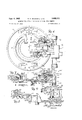
- FIG. 4 is a detail view mostly in right side elevation illustrating the tool storage magazine which is shown assembled to the machine in FIG. 1;
- FIG. 5 is a view partly in elevation and partly in vertical section taken along the plane represented by the line 55 in FIG. 4;
- FIG. 6 is a left side elevational view of the magazine shown in FIG. 4;
- FIG. 7 is a vie-w partly in plan and partly in horizontal section taken through the center of the view of the magazine in FIG. 6;
- FIG. 8 is a detail fragmentary view partly in plan and partly in horizontal section taken along the plane represented by the line 8--8 in FIG. 6;
- FIG. 9 is a fragmentary detail plan view showing the detent mechanism that is depicted in FIG. 6;
- FIG. 10 is a detail view of the hydraulic tool change arm actuating unit shown substantially in vertical section taken along the plane represented by the line 1010 in FIG. 6;
- FIG. 11 is a view partly in plan and partly in horizontal section taken along the plane represented by the line 11-11 in FIG. 10;
- FIG. 12 is a fragmentary detail rear view illustrating the arrangement of the switches that are partially shown in FIG. 11;
- FIG. 13 is a detail perspective view of the cam for actuating the switches shown in FIG. 12;
- FIG. 14 is a view of the reading head, substantially in right side elevation with parts broken away to reveal the operating mechanism
- FIG. 15 is a bottom view of the reading head shown in FIG. 14, the reading head being illustrated engaging the coding on a tool;
- FIG. 16 is a'bottom view of the hydraulic unit depicted in FIG.
- FIG. 17 is a detail view partly in side elevation and partly in vertical section illustrating the forward portion of the machine tool spindle
- FIG. 18 is a detail view partly in side elevation and partly in vertical section illustrating the rearward portion of the machine tool spindle shown in FIG. 17;
- FIG. 19 is a detail view partly in side elevation and partly in vertical section taken through the center of a tapping tool adapted to operate with the spindle shown in FIGS. 17 and 18;
- FIGS. 20 to 20E inclusive are a series of diagrammatic perspective views of the front of the spindle and magazine of the machine tool shown in FIG. 1, illustrating the various steps in the cycle of operation of the tool change arm in changing the cutting tool in the spindle;
- FIGJ21 is a diagrammatic view of the hydraulic circuit
- FIGS. 22 to 28 inclusive are a series of diagrammatic views illustrating the operation of the hydraulic unit in producing the several rotary positions of the tool change arm;
- FIGS. 22A to 28A inclusive are a series of diagrammatic views showing the several rotary positions of the tool change arm corresponding to the positions of the actuating plunger of the hydraulic unit as shown in FIGS. 22 to 28
- FIGS. 22B to 28B inclusive are a series of diagrammatic'views of the switch actuating cam in relation to the switch rollers which are actuated by it as 'seen from the front and which rotates with the tool change arm, the cam being shown in its various rotary positions corresponding to the rotary positions of the tool change arm as depicted in 'FIGS. 22A to 28A respectively;
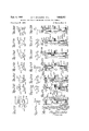
- FIG. 29 is a diagrammatic view of the electrical circuit for selecting the desired tool for location at the tool change station
- FIG. '30 is an electrical wiring diagram illustrating the control circuit for controlling the operation of the various components in completing a tool change
- FIG. 31 is an electrical wiring diagram of the control circuit employed for controlling the performance of a threading operation
- FIG. 32 is a detail bottom view of an alternate form of reading head for reading the identifying coding on the tools in thestorage magazine;
- FIG. 33 is a view in side elevation illustrating the reading head shown in FIG. 32;
- FIG. 34 is an enlarged fragmentary sectional View of the coding arrangement on a tool in relation to the electrical brushes employed with the reading head depicted in FIG. 32;
- FIG. 35 is an electrical wiring diagram showing the tool selection circuit utilized with the reading head that is illustrated in FIG. 32;
- FIG. 36 is a detail view of the tool change arm shown substantially in section taken along the plane represented by the line 36-36 in FIG. 37;
- FIG. 37 is a front view of the tool change arm shown in FIG; 36 with the outer plate omitted to reveal the mechanism underneath it;
- FIG. 38 is a fragmentary view in section taken along the plane represented by the line 38-38 in FIG. 37 to illustrate the mounting of the slide in the front plate of the tool change arm;
- FIG. 39 is a detail front view of the slide which is shown assembled to the tool change arm in FIGS. 36 and 37.
- FIG. 1 illustrating a machine tool incorporating the features of the present invention.
- the machine com-prises generally a bed 40 which slidably supports an upstanding column 41.
- the bed 40 is provided with horizontal ways 42 which are engaged by complementary ways (not shown) formed at the bottom of the column 41 to support the column for sliding movement along the length of the bed 40.
- a plurality of slidable plates 43 are attached to the bed 40 and the column 41 in telescoping arrangement so as not to interfere with the longitudinal movement of the column 41 while providing a protective covering over the ways 42 to prevent the chips which are formed during a machining operation from falling onto the ways 42.
- the column 41 is provided with vertical ways 48 for engagement by complementary ways (not shown) formed on a saddle 49 for slidably supporting the saddle in a vertical path of travel.
- Vertical movement of the saddle 49 in either direction is effected by rotating a screw 50 which is in threaded engagement with a recirculating ball bearing thread nut (not shown) that is fixed to the saddle 49.
- the screw 56 is rotatably supported by the column 41, being journalled at its upper end in a cap 51 that is secured to the top of the column 41 and which extends from the column beyond the ways 48 for receiving the screw 50.
- the lower end of the screw 50 is journalled in a suitable bearing (not shown) that is attached to the column 41 beneath the top of the bed 40.
- the screw 50 may be rotated in either direction by a motor 52 mounted on top of the cap 51 and connected to rotate the screw 50 for actuating the saddle 49 in its path of travel by power.
- a pair of hydraulic piston and cylinder mechanisms 53 are mounted on top of the cap 51 for connection to the saddle 49 by connecting rods 54 and are arranged in a well known manner to counterbalance the weight of the saddle 49. and its associated mechanism.
- the spindle head 61) rotatably supports a spindle 62 that is adapted to carry a tool 65 to rotate with the spindle 62 for performing a machining operation.
- the spindle 62 is rotated by a suitable motor (not shown) in a well known manner.
- the spindle 62 supports the tool 65 in position to operate upon a workpiece (not shown) located on a rotary index table 66 which is mounted on the top of a pedestal 67 that is secured to the front face of the bed 40.
- the rotary table 66 is adapted to receive the workpieces attached to pallets (not shown) which are transported to the table 66 onto a pair of rails 64 by a suitable conveyor (not shown) and clamped to the rails for completely automatic operation.
- a conventional rotary index table may be provided with each individual workpiece being clamped thereto manually by the operator.
- the machine tool illustrated in FIG. 1 is equipped with an automatically operable mechanical tool changer mounted on the saddle 49 and constructed in accordance with the teachings of the present invention.
- a plurality of tools 65 are stored in a magazine generally identified by the reference numberal 70.
- a tool change arm 71 is carried by a hydraulic unit 72 which serves to actuate the tool change arm 71 for performing its function of withdrawing a selected tool 65 from the magazine 70 and inserting it into the spindle 62 to render it operative for performing a machining operation.
- the tool change arm 71 operates to withdraw the tool 65 already located in the spindle 62 and places it in the magazine 70 for storage.
- the hydraulic unit 72 is hingedly carried by the tool changerfor pivotal movement about a vertical axis for the purpose of swinging the tool change arm 71 from an inoperative to an operative position, the inoperative position serving to locate the tool change arm 71 and its associated hydraulic unit 72 in a position where they will not interfere with the movement of the spindle head 60 for performing a machining operation.
- FIGS. 1 and 2 illustrate the hydraulic unit 72 swung to locate the tool change arm 71 in its inoperative position out of the path of travel of the spindle head 60, being located against the peripheral face of the magazine 70.
- the hydraulic unit 72 is pivoted to the left as viewed in FIG. 2 to swing the tool change arm 71 outwardly 90 from the position shown in FIG. 2 to the position depicted in FIG. 3 where it is properly located for performing a tool changing operation.
- the tool change arm 71 is a U-shaped member with one leg of the U being provided with a tool grip or carrier 73 and the other leg being provided with an identical tool grip or carrier 74, the two grips 73 and 74 extending outwardly and transversely of the legs of the U-shaped tool change arm 71.
- the tool grips 73 and 74 are each provided with a pair of substantially semicircular surfaces 75 for receiving a collar 119 secured to each tool 65.
- the tool grips 73 and 74 are provided with rollers 77 for yieldably retaining the tools 65 within the semicircular surfaces 75 in a manner to be subsequently described.
- FIGS. 20 to 20E inclusive diagrammatically illustrate a cycle of operation of the tool change arm 71 in replacing a tool 65 in the spindle 62.
- FIG. 20 shows the tool change arm 71 in its inoperative position located against the peripheral face of the drum 70.
- the hydraulic unit 72 is pivoted about a vertical axis in a clockwise direction as viewed from the top to swing the tool change arm 71 90 from its inoperative position to its operative position as illustrated in FIG. 20A.
- the selected tool 65 is also pivoted outwardly of the magazine 70* to render it accessible to the tool change arm 71 as depicted in FIG. 20A.
- the tool 65 that is extending from the magazine 7 is provided with a milling cutter 68' while the tool 65 located in the spindle 62 is provided with a drill 68, and the illustrated cycle shows the tool change arm 71 replacing the drill 68 in the spindle 62 by the tool 65 carrying the milling cutter 68.
- the grips '73 and 74 have grasped the two tools 65 for the purpose of withdrawing them from the spindle 62 and the magazine 70.
- the tool change arm 71 is therefore moved forwardly by the hydraulic unit 72 and the two tools 65 move with it out of the spindle 62 and the magazine 70 as shown in FIG. 20C.
- the tool change arm 71 is rotated 180 in a clockwise direction as viewed from the front of the machine and as indicated by the arrows in FIG. 20C to the position depicted in FIG. 20]) wherein the drill 68 has been moved from alignment with the spindle 62 into alignment with the magazine 70, and the milling cutter 63' has been moved from alignment with the magazine 70 into alignment with the spindle 62.
- the tool change arm 71 is moved in a counterclockwise direction as indicated by the arrows in FIG. 20E to return it to the vertical position depicted in FIG. 20A, the tool grips 73 and 74 being thus moved out of engagement with the respective tools 65 and the tool change has been completed, the drill 68 having been replaced in the spindle 62 by the selected milling cutter 68.
- the tool change arm 71 is in the vertical position illustrated in FIG. 20A it is extending from the machine and would interfere with the performance of a machining operation.
- the hydraulic unit 72 is therefore pivoted in a counterclockwise direction as viewed from the top to swing the tool change arm 71 to its inoperative position against the peripheral face of the magazine 70 as illustrated in FIG. 20.
- the tool change arm 71 is being swung to its inoperative position, the tool 65 that has been placed in the magazine 70 is likewise pivoted into the magazine 70 for storage and the latter may be operated in a manner to be subsequently described for selecting the succeeding tool which is to be placed in the spindle 62 by the tool change arm 71.
- a plate shown in FIG. 1 is secured to the right side of the saddle 49, and the magazine 70, in turn, is mounted on the plate 80 for movement with the saddle 49 in its vertical path of travel.
- the detailed construction of the magazine 70 is clearly shown in FIGS. 4 to 7 inclusive and comprises a tool carrying ring 01 rotatably supported between a front plate 82 and a back plate 83.
- the tool carrying ring 81 is provided with an integrally formed internal ring gear 84 and is rotatably supported by a pair of ball bearings and 86 located on either side of the ring gear 84-.
- the front plate 82 and the back plate 83 are provided with annular shoulders that bear on the inner races of the ball bearings 85 and 86 respectively while the tool carrying ring 81 is likewise provided with a pair of annular shoulders upon which the outer races of the bearings 85 and 86 bear. With this arrangement, the tool carrying ring 81 is firmly supported between the front plate 82 and the back plate 83 but is freely rotatable therebetween.
- the back plate 83 is provided with a central opening 91 to form a recess for receiving a portion of the operating mechanism that will be subsequently described.
- the opening 91 is defined by a hub 92 that extends laterally of the back plate 83 toward the inner surface of the front plate 82.
- a plurality of cap screws 93 extend through suitable openings in the front plate 82 into threaded engagement with the hub 92 to operably secure the front plate 32, the tool carrying ring 81, the back plate 83, and the ball bearings 85 and 86in the proper relationship.
- the upper portion of the back plate 8-3 is provided with threaded openings 94- while similar threaded openings 95 are formed in the lower portion of the back plate 83 for receiving suitable screws which serve to attach the magazine 70 to the plate 80 for mounting the magazine 70.
- the purpose of the tool carrying ring 81 is to carry the variety of tools 65 in storage and to transfer or move the selected tools individual-1y to a tool change or ready station where they may be made accessible to the tool change arm 71.
- the ring 81 is provided with an outwardly extending annular ledge 106 upon which are fixedly mounted a plurality of brackets 107 in equally spaced relationship and which extend radially outwardly of the ring '81.
- Each of the brackets 107 includes a pair of spaced outwardly extending legs 108 which rigidly carry a pin 109 that extends across the gap between each pair of legs 108.
- a plate 110 is provided with a suitable opening for receiving the pin 109 and is straddled by the legs 108 so that it is pivotally supported by the bracket 107 with one plate 110 being carried by each of the plurality of brackets 107.
- a plurality of tool storage sockets 115 are provided, with a plate 110 being secured to the peripheral surface of each of the tool storage sockets 115, the latter being utilized for receiving the variety of tools 65 so that each of the tools 65 that are available for operation with the machine may be stored within the magazine 70 by insertion into one of the tool storage sockets 115.
- thirty tool storage sockets 115 are shown to accommodate the storage of thirty tools 65 and since one of the tools 65 may be located in the spindle 62, thirty-one different tools 65 may be made available.
- tool storage sockets 11 are shown as an exemplary embodiment only but other quantities may be provided to suit the require ments of a particular application.
- tools 65 are illustrated as being contained within two storage sockets 115 for the purpose of convenience but such tools 65 may be contained in all or any portion of the storage sockets .115.
- the tool 65 has been referred to generally but, as shown in FIG. 17, it comprises the cutter 68 extending into a cylindrical shell 116 which is provided with an internal thread for receiving a plug 117 against which the rrearmost end of the cutter 68 is abutted.
- the forward end of the bore of the shell 116 is enlarged for receiving a longitudinally split sleeve 118 that embraces the periphery of the cutter 68.
- the periphery of the forward end of the shell 116 is provided with an external thread for threadedly receiving a collar 119 that serves to compress the split sleeve 118 for locking the cutter 68 to the shell 116.
- the sleeve 118 is provided with two tapered annular surfaces 120 and 121 which are engaged by cooperating tapered annular surfaces formed on the shell 116 and the collar 119 respectively.
- the collar 119 is threaded onto the shell 116, the several cooperating tapered surfaces are engaged to compress the sleeve 118 about the cutter 68 to rigidly clamp the cutter 68 to the shell 116.
- the cutting portion of the cutter 68 extends forwardly of the collar 119 so that it may engage a workpiece for performing a machining operation.
- the portion of the shell 116 that extends rearwardly of the collar 119 is inserted into the axial bore of the storage socket 115.
- the tool 65 is yieldably retained within the socket 115 by a plunger 125 that is located within a bore formed in the plate 110 with its axis extending transversely of the axis of the socket '115.
- a spring 126 has one end bearing against the plunger 125 and is compressed by a plug 127 that is threaded into the bore containing. the spring 126.
- the plunger 125 also extends through a suitable transverse opening formed in the storage socket 115 so that it is forced into engagement with the periphery of the shell 1 16 within the tool storage socket 115 to yieldably retain the tool 65 therein.
- the tool 65 which is selected for insertion into the spindle 62 by the tool change arm 71 must be moved to the tool ready station 105 of the magazine 70 and this is accomplished by power through the operation of a motor 130.
- a hydraulic motor is shown as an exemplary embodiment although it is to be understood that an electric motor could likewise be utilized for this purpose.
- An output shaft 131 of the motor 130 is connected to drive a gear train generally identified by the reference numeral 132 and which includes a gear 133 that meshes with the internal ring gear 84 of the tool carrying ring 81.
- actuation of the motor 130 will serve to rotate the ring 81 to move the tool storage sockets 115 and the tools 65 which they carry, in a circular path.
- Each of the tools 65 is identified by a number from one to thirty-one inclusive and they are each coded in accordance with the binary system to indicate the number of the tool.
- the binary system to indicate the number of the tool.
- only two numerals, 0 and '1 are used in the binary numbering system, and since thirty-one numbers are required in the illustrated embodiment, five digits of the binary system must be provided.
- the number 00001 will identify tool No. 1
- the binary number 1111 1 will identify tool No. 3-1.
- Five peripheral strips about the collar 119 are therefore designated to constitute the coding, with each of the strips representing one of the digits of the binary system in the present example.
- Each of these peripheral strips may be provided with a peripheral land or ring 135 to indicate the numeral 1 for that particular digit of the binary number, and the absence of a peripheral land 135 along any of the peripheral strips indicates the numeral 0 for that particular digit of the binary system.
- Such coding of the tools 65 is read by a tool selector or reading head generally identified by the reference numeral 1140.
- the identification number of the desired tool is impressed upon the electrical control system either manually or automatically in a manner to be later described. Then, as the ring 81 is rotated, the tool reading head will read the code on the collars 119 and when the number read on the collar 119 by the reading head 140 coincides with the number impressed upon the electrical control system, the electrical control system will operate to deactuate the motor 130 and thereby stop the rotation of the ring 81. As best shown in FIGS.
- the tool reading head 140 includes five movable fingers 141 that extend from a housing 142 into engagement with five peripheral strips on the collars 119 of the tools 65 that have been designated to contain the coding for identifying each tool.
- Each of the fingers 141 is yieldably urged forwardly into engagement with the collar 119 by a spring 143 that urges its associated finger 141 into the path of travel of the collars 119 as they move in their circular path of travel with the rotation of the ring 81.
- Each of the fingers 141 includes a rod 144 that extends rearwardly into the housing 142.
- the end of each of the rods 144- is connected to a movable contact bar 145 of a switch that is generally identified by the reference numeral 146.
- the switches 146 are double throw switches and each is provided with two stationary contacts 147 and 148.
- the springs 143 as previously mentioned, urged their associated fingers 141 forwardly and the movable contact bar 145 moves with its associated finger 141 into contact with the stationary contact 147.
- a closed contact is therefore normally maintained between the movable contact bar 145 and the stationary contact 147.
- the five fingers 141 are in alignment with the five peripheral strips on the collar 119 which contain the coding of the tool.
- the fingers 141 cooperating with these particular peripheral strips will be engaged by the lands 135 and moved rearwardly toward the housing 142 against the force of the spring 143 to move their associated contact bars 145 out of engagement with the contacts 147 and into engagement with the contacts 148.
- the latter In the absence of a land 135 on the particular strip associated with a finger 141, the latter will fail to be actuated and its movable contact bar 145 will remain in engagement with the contact 147.
- the collar 119 there shown has a land 135 on each of the first four peripheral strips which contain the coding while the fifth peripheral strip has no such land 1 35.
- the first four fingers 141 have therefore been actuated rearwardly to indicate the numeral 1 for the first four digits of the binary number.
- the fifth finger 141 has not been so actuated by reason of the fact that the peripheral strip on the collar 119 with which it cooperates does not include a land 135 and this fifth digit of the binary number will therefore be a 0.
- the coding on the collar 119 has therefore indicated the binary number 01111 to signal the presence at the operating station of the tool that is identified as No. 15.
- the motor 130 When the number impressed upon the tool reading head 140 by the coding on the particular collar 119 coincides with the number impressed upon the electrical control system for selecting the desired tool, the motor 130 will be deactuated to terminate the forward rotation of the ring 81. When this occurs the ring 81 will have overrun the desired position so that the selected tool 65 will be slightly beyond the tool change station 105.
- the electrical control system therefore operates to immediately effect a reversal of the rotation of the motor 130 at a creep rate until the desired tool 65 is accurately located at the tool change station 105, the reverse rotation of the motor 130 being terminated by actuation of a limit switch 150 which is shown in FIG. 4.
- the precise control of the motor 130 for accurately locating the selected tool 65 at the tool change station 105 is achieved by means of the unique positioning mechanism illustrated in FIG. 4 and generally identified by the reference numeral 155.
- the positioning mechanism 155 comprises a housing 156 that pivotally supports a rocker arm 157 by means of a pin 158 which is carried by the housing 156 and is in pivotal engagement with one end of the rocker arm 157.
- the rocker arm 157 overlies a pair of flats 160 that are formed on a coupling sleeve 161 which is keyed to rotate with the output shaft 131 of the motor 130.
- the rocker arm 157 extends from the pin 158 across the housing 156 and beyond its edge where it is disposed to engage a plunger 162 of the limit switch 150 for the purpose of actuating the switch.
- hydraulic pressure is admitted to the lower end of a cylinder 163 which is formed in the housing 156, the hydraulic pressure serving to force a plunger or actuator 164 that is located in the cylinder 163 upwardly.
- the plunger .164 is disposed to engage the rocker arm 157 and as the plunger 164 is moved upwardly by the hydraulic pressure, it functions to pivot the rocker 157 upwardly to the position shown by broken lines in FIG. 4 out of engagement with the coupling sleeve 161 so that it will not interfere with the rotation of the sleeve.
- the force transmitted through the plunger 164 operates against a spring 165 that yieldably applies pressure on the opposite side of the rocker arm 157 to urge it toward its downward pivotal position.
- Each half revolution of the output shaft 131 of the motor 130 operates to rotate the ring 81 through an angle of 12 so that one of the tool storage sockets 115 is moved out of the tool change station 105 and the succeeding storage socket 115 is brought into alignment with the tool change station 105.
- the coupling sleeve 161 is so arranged that when either one of the flats 160 is in alignment with the bottom surface of the rocker arm 157, so that the two surfaces are in full bearing engagement, a tool storage socket 115 is accurately located at the tool change station 105.
- Actuation of the limit switch 150 serves to de-energize a solenoid valve for terminating operation of the motor 131), and one of the tool storage sockets 115 containing the selected tool 65 will then be accurately positioned at the tool change station 105.
- the tool change mechanism may then be operated to replace the tool 65 in the spindle 62 with another tool 65 withdrawn from the tool storage socket 115 at the tool change station 105.
- the rotation of the ring 81 to position the selected tool at the tool change station 105 may occur while a machining operation is being performed with the tool 65 that is in the spindle 62 and that when such machining operation is completed the succeeding desired tool 65 will be located at the tool change station 105 and the tool change mechanism may be operated immediately to effect the tool change in the spindle 62.
- each of the tool storage sockets 115 is pivotally supported by one of the brackets 107.
- the back end of each of the storage sockets 115 is provided with a beveled surface which engages a complementary annular beveled surface 171 formed on the periphery of the back plate 83.
- the beveled surfaces 170 of the several tool storage sockets 115 slide along the stationary beveled surface 171 of the back plate 83 and such engagement with the beveled surface 171 prevents the sockets 115 from pivoting in an outward direction.
- the beveled surface 171 extends about the entire periphery of the back plate 83 with the exception of the portion at the tool change station 105 where it is broken to permit the outward pivotal movement of the socket 115 at that station.
- the storage socket 115 at the tool change station 105 and containing the selected tool 65 must be pivoted outwardly so that the axes of the socket 115 and its associated tool 65 extend substantially perpendicular to the axis of the magazine.
- the tool storage socket 115 must therefore be pivoted approxi mately 90 to move its associated tool 65 outwardly of the periphery of the magazine.
- Such movement of the selected storage socket 115 is produced by a pivot mechanism generally identified by the reference numeral 175 and located at the tool change station 105.
- the pivot mechanism 175 is clearly shown in FIGS. 6 and 7, and is actuated by a piston and cylinder mechanism 176 which is mounted on the front plate 82.
- the piston and cylinder mechanism 176 includes a piston rod 177 having a plate 178 fixed to its extending end.
- the plate 178 is attached to a plunger 180 which is slidably supported for axial movement by a guide 181 that is carried by the front plate 82.
- the plunger 180 is provided with a beveled end 182 for engagement with a complementary inclined surface 183 formed on the plate 110, one plate 110 being attached to each of the tool storage sockets 115 as previously described.
- the plunger 180 is shown in its retracted position in FIG. 7, the connecting rod 177 being withdrawn into the piston and cylinder mechanism 176.
- the piston and cylinder mechanism 176 is actuated to move the connecting rod 177 to the right, as viewed in FIG. 7 to move the plunger 180 with it.
- the beveled end 182 of the plunger 180 then engages the inclined surface 183 of the plate 110, and as the movement of the plunger 180 continues to the right, it pivots the tool storage socket 115 in a counterclockwise direction, as viewed in FIG. 7, to the position illustrated by broken lines.
- the tool 65 With the tool storage socket 115 in this position, with its axis substantially normal to the axis of the magazine 7 0, the tool 65 extends outwardly of the magazine 70 in position to be engaged by one of the tool grips 73 or 74 of the tool change arm 71.
- the plate 178 In order to condition the electrical control system for the succeeding sequences of the cycle, the plate 178 extends laterally of the connecting rod 177, as shown in FIG. 4, in position to engage the plungers of a pair of limit switches 184 and 185. When the plunger 180 is retracted, as illustrated in FIGS. 4 and 7, the plate 178 engages the plunger of the limit switch 184 to actuate the switch.
- the plate 178 releases the plunger of the limit switch 184 and when the plunger 180 reaches its forward limit of movement, the plate 178 engages the plunger of the limit switch 185 to actuate the switch for the purpose of indicating that a tool 65 is extending outwardly of the magazine 70 and the tool is in position to be engaged by the tool grips of the tool change arm 71.
- the positioning mechanism 155 operates to accurately locate the selected tool 65 at the tool change station 105. However, if a slight displacement of the tool 65 should occur, it will be accurately aligned at the tool change station 105 by a pair of guides 190 and 191 during the pivotal movement of its associated storage socket 115.
- the guides 190 and 191 are secured to the edge of a pair 'of plates 208 and 209, as best shown in FIG. 5, and are accurately located to form a space between them conforming to the spacing of a pair of flat surfaces 192 formed on the periphery of the tool storage sockets 115.
- the location of the flat surfaces 192 on the tool storage sockets 115 may be best seen in FIG. 4, and the dimension between these two flat surfaces is accurately maintained to closely fit into the space between the guides 190 and 191.
- the flat surfaces 192 move into the space between the guides 190 and 191 to accurately locate the tool storage socket 115 at the tool change station 105.
- the forward end of the guide 190 is provided with a tapered surface 193 while the guide 191 is provided with a similar tapered surface 194 at its forward end.
- These tapered surfaces 193 and 194 serve to enlarge the gap between the guides 190 and 191 at their forward ends to facilitate the entrance of the flat surfaces 192 of the tool storage socket 115.
- one of the flat surfaces 192 will engage either the tapered surface 193 or the tapered surface 194 of the guides 190 and 191 respectively, depending upon the direction of the displacement, and as the pivotal movement of the tool storage socket 115 continues, it will cause a slight shifting of the tool carrying ring 81 to accommodate the movement of the flat Surfaces 192 into the space between the guides 190 and 191 to thereby accurately locate the tool storage socket 115 at the tool change station 105.
- the outward pivotal position of the tool storage socket 115 at the tool change station 105 is accurately located by a stop bar 201 that extends across the gap between the guides 190 and 191 with one end of the stop bar 201 being secured .to the guide 190 and its other end being attached to the guide 191.
- the stop bar 201 cooperates with an abutment surface 202 formed at the rear end of each of the tool storage sockets 115 for accurately locating the tool storage socket 115 in its outwardly extending position for effecting a tool change.
- This position of the tool storage socket 115 is shown in broken lines in FIG. 7 indicating the tool 65 extending outwardly of the magazine 70 and the abutment surface 202 of the socket 115 in tight engagement with the edge of the stop bar 201. Therefore, when the pivotal movement of the storage socket 115 is completed for outwardly locating a tool 65, the hydraulic pressure in the cylinder 176 is continued to force the abutment surface 202 in tight engagement with the stop bar 201 to firmly maintain the tool storage socket 115 in position while a tool change is being effected.
- the tool storage sockets 115 are prevented from pivoting outwardly of their normal position in the magazine 70 at any location other than at the tool change station by engagement of their beveled surfaces 170 with the annular beveled surface 171 formed on the periphery of the back plate 83.
- the back plate 83 is broken at the tool change station 105 to permit the pivotal movement of the storage sockets at this location, but since the tool storage sockets 115 pass the tool change station 105 when the tool carrying ring 81 is benig rotated, means are provided at the tool change station 105 to prevent the outward pivotal movement of the tool storage sockets 115 except by operation of the piston and cylinder mechanism 176.
- a slide 205 is slidably supported between the guides 190 and 191 and a pair of shoulders 207 formed on the plates 208 and 209, as best shown in FIG. 5.
- the slide 205 is provided with a beveled surface 206 at its forward end which conforms with the beveled surface 171 formed on the back plate 83.
- the slide 205 is in its forward position with its beveled surface 206 in alignment with the beveled surface 171.
- the beveled surface 206 therefore fills the gap at the tool change station 105 and constitutes a continuation of the beveled surface 171 in order to avoid pivotal displacement of the storage sockets 115 at the tool change station 105 until rotation of the ring 81 is terminated and the piston and cylinder mechanism 176 is actuated.
- the slide 205 While the plunger 180 is moving forwardly to pivot a tool 65 outwardly of the magazine 70, the slide 205 is retracted to withdraw its beveled surface 206 and permit the outward pivotal movement of the storage socket 115.
- Such retraction of the slide 205 is produced by a gear 210 that is in meshing engagement with a gear rack 211 formed on the plunger 180 and a gear rack 212 formed on the interior surface of the slide 205. Therefore, as the plunger 180 is moved forwardly to pivot a tool 65 outwardly, it causes rotation of the gear 210 which, in turn, effects a retraction of the slide 205 by reason of its engagement with the gear rack 212 formed on the slide 205. The beveled surface 206 of the slide 205 will then be out of engagement with the beveled surface on the storage socket 115, as indicated by the broken lines in FIG. 7.
- the slide 205 serves the further purpose of returning the storage socket 115 to its normal position within the magazine 70 when the plunger is retracted. Retraction of the plunger 180 causes the gear 210 to rotate and thereby move the slide 205 forwardly. As the slide 205 moves forwardly it engages the beveled surface 170 of the storage socket 115 and forces it to pivot inwardly into the magazine 70 after the tool change has been completed. The slide 205 then assumes its normal position with its beveled surface 206 in alignment with the bevel surface 171 of the back plate 83 to prevent inadvertent pivotal movement of the tool storage sockets 115 as they pass the tool change station 105.
- a detent generally identified by the reference numeral 213 is mounted adjacent to the slide 205.
- a detent ball 214 is urged into a suitable recess 215 formed in the outer surface of the slide 205, the ball being urged toward the slide 205 by a spring 216.
- the recess 215 is provided to establish the retracted position of the slide 205.
- the pivot mechanism 175 serves the further purpose of pivoting the hydraulic unit 72 for swinging the tool change arm 71 from its retracted or inoperative position, as illustrated in FIG. 2, to its operative position as depicted in FIG. 3.
- the latter is provided with a pair of laterally extending lugs 221 and 222 which are provided with central openings for receiving a hinge pin 223.
- the back plate 83 is provided with similar lugs 224 and 225 that are located directly adjacent to the lugs 221 and 222 respectively but within the space between them, the lugs 224 and 225 being likewise provided with central openings for receiving the hinge pin 23.
- the pin 223 therefore extends through the openings formed in the four lugs 221, 222, 224 and 225 so that the hydraulic unit 72 is pivotally carried by the back plate 83.
- the pivotal outward movement of the tool change arm 71 occurs at the same time that a tool 65 is being pivoted outwardly of the magazine 70.
- the drive for pivoting the hydraulic unit 72 is therefore taken from the gear 210 which is keyed to a shaft 230' that is journalled in the plates 208 and 209 as clearly shown in FIG. 5.
- the shaft 230 extends beyond the plate 209 to receive a gear 231 which is keyed thereto.
- a cooperating wide tooth gear 232 is ro-tatably supported by a stub shaft 233 that is carried by the plate 209 and is in meshing engagement with the gear 231, being provided with a laterally extending lug 234 as best shown in FIG. 8.
- a pin 235 is attached to the lug 234 for receiving one end of a link 240 and pivotally supporting the latter.
- the link 240 is connected to a similar link 241 by a turnbuckle 242 and the end of the link 241 is pivotally carried by a pin 243.
- the turnbuckle 242 serves to adjust the distance between the ends of the links 240 and 241 to accommodate the spacing of the pins 235 and 243 respectively.
- the pin 243 is secured to the hinge lug 222 of the hydraulic unit 72 at one corner thereof as shown in FIG. 8.
- the tool change arm 71 will therefore move with the pivotal movement of the hydraulic unit 72 from its inoperative position as illustrated in FIG, 2, to its operative position, as shown in FIG. 3. Upon completion of the tool change, the reverse movement, of course, will occur to again retract the tool change arm 71.
- a bracket 248 is provided for carrying an adjustable stud 249 and a detent mechanism 250, as shown in FIGS. 6 and 9.
- the stud 249 is threadedly carried by the bracket 248 and is locked in the desired position by a lock out 251. It is disposed in alignment with the hinge lug 221 of the hydraulic unit 72, and as the latter, is pivoted to swing the tool change arm 71 to its inoperative position, the edge of lug 22 1 abuts the end of the stud 249 to prevent further pivotal movement of the hydraulic unit 72 in this direction.
- a cam plate 255 is secured to the top surface of the hinge lug 221 to pivot with it and cooperate with the detent mechanism 250 which is disposed directly above the stud 249.
- the detent mechanism 250 comprises a detent plunger 256 slidably supported within a cylindrical opening 257 formed in the bracket 248.
- the plunger 256 is urged to the right, as viewed in FIG. 9, by a spring 258 which is likewise contained Within the cylindrical opening 257 with one end bearing against the plunger 256 and the opposite end bearing against a plug 259 which is threaded in the open end of the cylindrical opening 257.
- a set screw 269 is threaded into the bracket 248 into a recess 261 formed in the detent plunger 256 for the purpose of permitting sliding movement of the plunger 256 within the cylindrical opening 257 while preventing the plunger from being ejected from the opening.
- the extending end of the plunger 256 is tapered to form a point 262 which bears against the edge of the earn 255 when the latter is positioned by the hydraulic unit 72 in its operating position with the tool change arm 71 swung to its operating position.
- the cam 255 is shown in FIG. 9 in solid lines, entirely free of the detent mechanism 250 when the hydraulic unit 72 is pivoted to the retracted position wherein the tool change arm 71 is in its inoperative position.
- the cam 255 occupies the position indicated by the broken lines with the point 262 of the plunger 256 bearing against the edge of the cam 255 for yieldably retaining the hydraulic unit 72 in this position.
- the hydraulic unit 72 After the hydraulic unit 72 has been pivoted to swing the :tool change arm 71 to its operative position, it functions to rotate the tool change arm 71 as well as to extend and retract it for completing the tool change as previously described.
- the hydraulic unit 72 includes a vertical cylinder 268 and a horizontal cylinder 269 that extends laterally from the vertical cylinder 268, as shown in FIGS. 10 and 11.
- the tool change arm 71 is secured to the end of a stub shaft 270, and a disk 273 is in serrated engagement with the stub shaft 270, as clearly illustrated in FIG. 11, so that the disk 273 will rotate with the shaft 270.
- the disk 273 is retained on the shaft 270 by a snap ring 274 to hold the assembly together.
- the stub shaft 270 is attached to the end of an internally splined sleeve 278 which is in splined engagement with a shaft 279 so that the sleeve 278 may be moved axially relative to the shaft 279 while maintaining a rotary driving connection therewith.
- the shaft 279 extends rearwardly of the sleeve 278 where it is journalled by a pair of ball bearings 280 and 281 which are carried by the cylindrical housing 268.
- a gear 282 is keyed to the shaft 279 between the ball bearings 280 and 281 and is in meshing engagement with a gear rack 283 formed on a vertical plunger 284 for imparting rotational move ment to the shaft 279 in a manner to be later described.
- the extension and retraction of the tool change arm 71 is effected by the axial movement of the sleeve 278 which is rotatably supported within a quill 290 that is slidably carried for axial movement within the horizontal cylinder 269, as clearly shown in FIG. 11.
- the sleeve 278 and its associated stub shaft 270 are rotatably supported within the quill 290 by a needle bearing 291 and a pair of ball bearings 292.
- a snap ring 293 engages the quill 290 and the inner edge of the needle bearing 291
Description
p 1962 w. E. BRAINARD ET AL 3,052,011
MACHINE TOOL WITH A MECHANICAL CUTTING TOOL CHANGER- Filed June 27, 1958 15 Sheets-Sheet 1 k 2 .P m CJMM m a y w M a. m 0 m w /ajiace fBrar'nahd, John AHansen, Eober'z A. Sea? In mun-i" I lllnulli' I l-ll ll Sept. 4, 1962 w. E. BRAINARD ET AL 3,052,011
MACHINE TOOL WITH A MECHANICAL CUTTING TOOL CHANGER Filed June 27, 1958 13 $heets -Sheet 2 %p&
Mai/ave Brar'wa rd J02]?! ,4. Hansen, fioberl' K. Sea uack (War/es B. Srpek, #071515 fd MACHINE TOOL WITH A MECHANICAL CUTTING TOOL CHANGER Filed June 27, 1958 Sept. 4, 1962 w. E. BRAINARD ET AL 13 Sheets-Sheet 3 John/1. 'l/nsew, Robert K Sed Sept. 4, 1962 r w. E. BRAINARD ET AL 3,052,011
MACHINE TOOL WITH A MECHANICAL CUTTING TOOL CHANGER Filed June 27, 1958 15 Sheets-Sheet 4 49'1Z55INVENTORS DWM Attorney Sept. 4, 1962 w. E. BRAINARD ET AL 3,052,011
MACHINE TOOL WITH A MECHANICAL CUTTING TOOL CHANGER l5 Sheets-Sheet 5 Filed June 27, 1958 INVENTORS Mai/ace E, 5rd iflardJafin A. A/a risen, Kobert' (Seofiam'cl; (kw/es 5 Srjoek,
BY 14% J Baec/I/e Attorney l3 Sheets-Sheetfi Sept. 4, 1962 w. E. BRAINARD ETAL MACHINE TOOL WITH A MECHANICAL CUTTING TOOL CHANGER Filed June 2'7, 1958 Sept. 4, 1962 w. E. BRAINARD ETAL 3,052,011
MACHINE TOOL WITH A MECHANICAL CUTTING TOOL CHANGER Filed June 27, 1958 13 Sheets-Sheet 7 DJAF p 1962 w. E. BRAINARD ETAL 3,052,011
MACHINE TOOL WITH A MECHANICAL CUTTING TOOL CHANGER Filed June 27, 1958 13 Sheets-Sheet 8 QM NCW QANQ %ww C A N AI M v ,k \k wk CR mm NAN Cw .Qwmw @NC NAN Cw mwwmw mmw w p 1962 w. E. BRAINARD ETAL 3,052,011
MACHINE TOOL WITH A MECHANICAL CUTTING TOOL CHANGER l3 Sheets-Sheet 9 Filed June 27, 1958 N UQ mm w Sept. 4, 1962 w. E. BRAINARD ETAL 3,052,011
MACHINE TOOL WITH A MECHANICAL CUTTING TOOL CHANGER Filed June 27, 1958 15 Sheets-Sheet 10 13 Sheets-Sheet 11 Sept. 4, 1962 w E. BRAINARD ET AL MACHINE TOOL WITH A MECHANICAL CUTTING TOOL CHANGER FiledJune 27, 1958 Sept. 4, 1962 w. E. BRAINARD ETI. 3,052,011
MACHINE TOOL WITH A MECHANICAL CUTTING TOOL CHANGER Filed June 27, 1958 15 Sheets-Sheet 12 I I u 445 4% 6, 2 6w wztcarxay United States Patent 3,052,011 MACHINE TOOL WITH A MECHANICAL CUTTING TOOL CHANGER Wallace E. Brainard, Milwaukee, John A. Hansen, Greendale, Robert K. Sedgwick, Waukesha, Charles B. Sipek, Hales Corners, and Hans J. Baechle, West Allis, Wis., assignors to Kearney & Trecker Corporation, West Allis, Wis., a corporation of Wisconsin Filed June 27, 1958, Ser. No. 744,976 35 Claims. (Cl. 29-26) The present invention relates generally to machine tools and more particularly to an improved machine tool equipped with a plurality of rotary cutting tools of different types that may be made individually operative automatically for performing a variety of machining operations on a single workpiece or on a number of workpieces in rapid succession.
It is a general object of the present invention to provide a machine tool with improved versatility.
Another object of the present invention is to provide an improved machine tool equipped with a plurality of rotary cutting tools that may be made individually operative for performing a variety of machining operations.
Another object of the present invention is to provide an improved machine tool equipped with a plurality of rotary cutting tools in which the operative cutting tools may be stored in a minimum space and made operative individually by power operated mechanical means.
Another object is to provide an improved machine tool with a rotary spindle and having automatically operated mechanical means that are operative to replace the cutting tool in the spindle.
Another object is to provide an improved machine tool with storage facilities for a plurality of rotary cutting tools that may be made operative individually by power operated mechanical means with the desired tool being selected and located to render it accessible to the mechanical means while a preceding machining operation is being performed.
Another object is to provide a machine tool with a plurality of rotary cutting tools that may be made individually operative for performing a variety of machining operations and having .an improved arrangement for controlling the machining operation when a threading tool is rendered operative.
Another object is to provide a machine tool with a group of rotary cutting tools that may be made individually operative for performing a variety of machining operations and having an improved arrangement for selecting the desired tool from the group and rendering it operative.
A further object is to provide a machine tool with a tool change arm that is automatically located in an inoperative position when not in use so that it will not interfere with the machining operations.
A further object is to provide a machine tool with a mechanical tool changer and having an improved electrical control system for automatically controlling the operation of the machine.
According to this invention the improved machine tool is equipped with a rotary spindle and a plurality of cutting tools adapted to be received by the spindle for rotation therewith to perform a machining operation. The cutting tools are stored in a magazine wherein they are carried by a rotatable ring so that they may be moved in a circular path within the magazine to locate the desired cutting tool at a tool change station where a mechanical tool changer may be operated to remove the cutting tool at the change station from the magazine and insert it into the spindle for performing the succeeding cutting operation. At the same time the tool changer removes the cutting tool that was utilized for the preceding ice machining operation from the spindle and inserts it into the magazine for storage.
The magazine includes a plurality of tool storage sockets supported on the rotatable ring and each of the storage sockets carries one of the cutting tools. The ring is therefore rotated to move the desired tool to the change station where it is made available to the tool changer and such movement may take place while the preceding machining operation is being performed. The cutting tools are provided with their own identifying binary coding which is read by a reading head as each tool passes the tool change station. When the coding of the tool at the change station corresponds with the binary number impressed upon the electrical control system, the rotation of the ring is terminated, and the tool storage socket carrying the desired tool is accurately located at the tool change station. Since the coding that is read by the reading head is carried by the cutting tool itself, it is not necessary that the tools be carried by the rotatable ring in any particular sequence and they can be inserted into any of the tool storage sockets. As a result, the tool changer may insert the tool that it withdraws from the spindle into the tool storage socket which previously carried the cutting tool that is being placed into the spindle.
The foregoing and other objects of this invention, which will become more fully apparent from the following detailed description, may be achieved by means of the exemplifying apparatus depicted in and set forth in this specification in connection with the accompanying drawings, in which:
FIGURE 1 is a perspective view of a machine tool incorporating the features of the present invention;
FIG. 2 is a fragmentary front View of the machine shown in FIG. 1, illustrating the saddle and magazine with the tool change arm being depicted in its inoperative position;
FIG. 3 is a fragmentary front view of the machine shown in FIG. 1, similar to the view in FIG. 2, but showing only the spindle head and magazine with the tool change arm being depicted in its operative position;
FIG. 4 is a detail view mostly in right side elevation illustrating the tool storage magazine which is shown assembled to the machine in FIG. 1;
FIG. 5 is a view partly in elevation and partly in vertical section taken along the plane represented by the line 55 in FIG. 4;
FIG. 6 is a left side elevational view of the magazine shown in FIG. 4;
FIG. 7 is a vie-w partly in plan and partly in horizontal section taken through the center of the view of the magazine in FIG. 6;
FIG. 8 is a detail fragmentary view partly in plan and partly in horizontal section taken along the plane represented by the line 8--8 in FIG. 6;
FIG. 9 is a fragmentary detail plan view showing the detent mechanism that is depicted in FIG. 6;
FIG. 10 is a detail view of the hydraulic tool change arm actuating unit shown substantially in vertical section taken along the plane represented by the line 1010 in FIG. 6;
FIG. 11 is a view partly in plan and partly in horizontal section taken along the plane represented by the line 11-11 in FIG. 10;
FIG. 12 is a fragmentary detail rear view illustrating the arrangement of the switches that are partially shown in FIG. 11;
FIG. 13 is a detail perspective view of the cam for actuating the switches shown in FIG. 12;
FIG. 14 is a view of the reading head, substantially in right side elevation with parts broken away to reveal the operating mechanism;
respectively;
FIG. 15 is a bottom view of the reading head shown in FIG. 14, the reading head being illustrated engaging the coding on a tool;
FIG. 16 is a'bottom view of the hydraulic unit depicted in FIG.
FIG. 17 is a detail view partly in side elevation and partly in vertical section illustrating the forward portion of the machine tool spindle;
FIG. 18 is a detail view partly in side elevation and partly in vertical section illustrating the rearward portion of the machine tool spindle shown in FIG. 17;
FIG. 19 is a detail view partly in side elevation and partly in vertical section taken through the center of a tapping tool adapted to operate with the spindle shown in FIGS. 17 and 18;
FIGS. 20 to 20E inclusive are a series of diagrammatic perspective views of the front of the spindle and magazine of the machine tool shown in FIG. 1, illustrating the various steps in the cycle of operation of the tool change arm in changing the cutting tool in the spindle;
FIGJ21 is a diagrammatic view of the hydraulic circuit;
FIGS. 22 to 28 inclusive are a series of diagrammatic views illustrating the operation of the hydraulic unit in producing the several rotary positions of the tool change arm;
FIGS. 22A to 28A inclusive are a series of diagrammatic views showing the several rotary positions of the tool change arm corresponding to the positions of the actuating plunger of the hydraulic unit as shown in FIGS. 22 to 28 FIGS. 22B to 28B inclusive are a series of diagrammatic'views of the switch actuating cam in relation to the switch rollers which are actuated by it as 'seen from the front and which rotates with the tool change arm, the cam being shown in its various rotary positions corresponding to the rotary positions of the tool change arm as depicted in 'FIGS. 22A to 28A respectively;
FIG. 29 is a diagrammatic view of the electrical circuit for selecting the desired tool for location at the tool change station;
FIG. '30 is an electrical wiring diagram illustrating the control circuit for controlling the operation of the various components in completing a tool change; 2
FIG. 31 is an electrical wiring diagram of the control circuit employed for controlling the performance of a threading operation;
FIG. 32 is a detail bottom view of an alternate form of reading head for reading the identifying coding on the tools in thestorage magazine;
FIG. 33 is a view in side elevation illustrating the reading head shown in FIG. 32;
FIG. 34 is an enlarged fragmentary sectional View of the coding arrangement on a tool in relation to the electrical brushes employed with the reading head depicted in FIG. 32;
FIG: 35 is an electrical wiring diagram showing the tool selection circuit utilized with the reading head that is illustrated in FIG. 32;
FIG. 36 is a detail view of the tool change arm shown substantially in section taken along the plane represented by the line 36-36 in FIG. 37;
FIG. 37 is a front view of the tool change arm shown in FIG; 36 with the outer plate omitted to reveal the mechanism underneath it;
FIG. 38 is a fragmentary view in section taken along the plane represented by the line 38-38 in FIG. 37 to illustrate the mounting of the slide in the front plate of the tool change arm; and,
FIG. 39 is a detail front view of the slide which is shown assembled to the tool change arm in FIGS. 36 and 37.
Reference is now made more particularly to the drawings and specifically to FIG. 1 thereof illustrating a machine tool incorporating the features of the present invention. The machine com-prises generally a bed 40 which slidably supports an upstanding column 41. To this end,
the bed 40 is provided with horizontal ways 42 which are engaged by complementary ways (not shown) formed at the bottom of the column 41 to support the column for sliding movement along the length of the bed 40. A plurality of slidable plates 43 are attached to the bed 40 and the column 41 in telescoping arrangement so as not to interfere with the longitudinal movement of the column 41 while providing a protective covering over the ways 42 to prevent the chips which are formed during a machining operation from falling onto the ways 42.
The column 41 is provided with vertical ways 48 for engagement by complementary ways (not shown) formed on a saddle 49 for slidably supporting the saddle in a vertical path of travel. Vertical movement of the saddle 49 in either direction is effected by rotating a screw 50 which is in threaded engagement with a recirculating ball bearing thread nut (not shown) that is fixed to the saddle 49. The screw 56 is rotatably supported by the column 41, being journalled at its upper end in a cap 51 that is secured to the top of the column 41 and which extends from the column beyond the ways 48 for receiving the screw 50. The lower end of the screw 50 is journalled in a suitable bearing (not shown) that is attached to the column 41 beneath the top of the bed 40. The screw 50 may be rotated in either direction by a motor 52 mounted on top of the cap 51 and connected to rotate the screw 50 for actuating the saddle 49 in its path of travel by power. A pair of hydraulic piston and cylinder mechanisms 53 are mounted on top of the cap 51 for connection to the saddle 49 by connecting rods 54 and are arranged in a well known manner to counterbalance the weight of the saddle 49. and its associated mechanism.
A spindle head or tool head which constitutes the operating station of the machine tool, is carried by the saddle 49 and is provided with horizontal ways 61 which engage complementary ways formed within the saddle 49 for supporting the spindle head 60 for a sliding cross feed movement in a horizontal path transverse to the direction of travel of the column 41. It is therefore apparent that the column 41, the saddle 49 and the spindle head 60 are each supported for movement in three mutually transverse paths of travel. The spindle head 61) rotatably supports a spindle 62 that is adapted to carry a tool 65 to rotate with the spindle 62 for performing a machining operation. The spindle 62 is rotated by a suitable motor (not shown) in a well known manner.
The spindle 62 supports the tool 65 in position to operate upon a workpiece (not shown) located on a rotary index table 66 which is mounted on the top of a pedestal 67 that is secured to the front face of the bed 40. In the illustrated embodiment, the rotary table 66 is adapted to receive the workpieces attached to pallets (not shown) which are transported to the table 66 onto a pair of rails 64 by a suitable conveyor (not shown) and clamped to the rails for completely automatic operation. However, it is to be understood, that a conventional rotary index table may be provided with each individual workpiece being clamped thereto manually by the operator.
The machine tool illustrated in FIG. 1 is equipped with an automatically operable mechanical tool changer mounted on the saddle 49 and constructed in accordance with the teachings of the present invention. To this end, a plurality of tools 65, each having a different cutter 68, are stored in a magazine generally identified by the reference numberal 70. A tool change arm 71 is carried by a hydraulic unit 72 which serves to actuate the tool change arm 71 for performing its function of withdrawing a selected tool 65 from the magazine 70 and inserting it into the spindle 62 to render it operative for performing a machining operation. At the same time, the tool change arm 71 operates to withdraw the tool 65 already located in the spindle 62 and places it in the magazine 70 for storage.
The hydraulic unit 72 is hingedly carried by the tool changerfor pivotal movement about a vertical axis for the purpose of swinging the tool change arm 71 from an inoperative to an operative position, the inoperative position serving to locate the tool change arm 71 and its associated hydraulic unit 72 in a position where they will not interfere with the movement of the spindle head 60 for performing a machining operation. FIGS. 1 and 2 illustrate the hydraulic unit 72 swung to locate the tool change arm 71 in its inoperative position out of the path of travel of the spindle head 60, being located against the peripheral face of the magazine 70. When a tool change is to be effected, the hydraulic unit 72 is pivoted to the left as viewed in FIG. 2 to swing the tool change arm 71 outwardly 90 from the position shown in FIG. 2 to the position depicted in FIG. 3 where it is properly located for performing a tool changing operation.
The tool change arm 71 is a U-shaped member with one leg of the U being provided with a tool grip or carrier 73 and the other leg being provided with an identical tool grip or carrier 74, the two grips 73 and 74 extending outwardly and transversely of the legs of the U-shaped tool change arm 71. The tool grips 73 and 74 are each provided with a pair of substantially semicircular surfaces 75 for receiving a collar 119 secured to each tool 65. The tool grips 73 and 74 are provided with rollers 77 for yieldably retaining the tools 65 within the semicircular surfaces 75 in a manner to be subsequently described.
FIGS. 20 to 20E inclusive diagrammatically illustrate a cycle of operation of the tool change arm 71 in replacing a tool 65 in the spindle 62. FIG. 20 shows the tool change arm 71 in its inoperative position located against the peripheral face of the drum 70. In response to a proper signal, the hydraulic unit 72 is pivoted about a vertical axis in a clockwise direction as viewed from the top to swing the tool change arm 71 90 from its inoperative position to its operative position as illustrated in FIG. 20A. While the tool change arm 71 is pivoting outwardly to the position shown in FIG. 20A, the selected tool 65 is also pivoted outwardly of the magazine 70* to render it accessible to the tool change arm 71 as depicted in FIG. 20A.
When the tool change arm is swung outwardly by the hydraulic unit 72 it is'in a Vertical position as shown in FIG. 20A and it is then rotated about a horizontal axis by the hydraulic unit 72 in a clockwise direction as viewed from the front of the machine. Such rotation moves the tool change arm 71 to the position shown in FIG. 20B wherein the grip 73 is in engagement with the tool 65 that is extending from the magazine 70 and the grip 74 is in engagement with the tool 65 that is carried by the spindle 62. It will be observed that the tool 65 that is extending from the magazine 7 is provided with a milling cutter 68' while the tool 65 located in the spindle 62 is provided with a drill 68, and the illustrated cycle shows the tool change arm 71 replacing the drill 68 in the spindle 62 by the tool 65 carrying the milling cutter 68.
With the tool change arm 71 positioned as illustrated in FIG. 2013, the grips '73 and 74 have grasped the two tools 65 for the purpose of withdrawing them from the spindle 62 and the magazine 70. The tool change arm 71 is therefore moved forwardly by the hydraulic unit 72 and the two tools 65 move with it out of the spindle 62 and the magazine 70 as shown in FIG. 20C.
After the two tools have been extracted from the spindle 62 and magazine 70, the tool change arm 71 is rotated 180 in a clockwise direction as viewed from the front of the machine and as indicated by the arrows in FIG. 20C to the position depicted in FIG. 20]) wherein the drill 68 has been moved from alignment with the spindle 62 into alignment with the magazine 70, and the milling cutter 63' has been moved from alignment with the magazine 70 into alignment with the spindle 62.
When the drill 68 and the milling cutter 63' have been thus realigned by one half of a revolution of the tool change arm 71 the latter will be retracted toward the machine to insert the two tools 65 into the spindle 62 and (a magazine 70 as illustrated in FIG. 20E so that the milling cutter 68' is inserted in the spindle 62 and the drill 68 is moved into the magazine 70 as shown in FIG. 20E.
From the position shown in FIG. 20E, the tool change arm 71 is moved in a counterclockwise direction as indicated by the arrows in FIG. 20E to return it to the vertical position depicted in FIG. 20A, the tool grips 73 and 74 being thus moved out of engagement with the respective tools 65 and the tool change has been completed, the drill 68 having been replaced in the spindle 62 by the selected milling cutter 68.
Although the tool change arm 71 is in the vertical position illustrated in FIG. 20A it is extending from the machine and would interfere with the performance of a machining operation. The hydraulic unit 72 is therefore pivoted in a counterclockwise direction as viewed from the top to swing the tool change arm 71 to its inoperative position against the peripheral face of the magazine 70 as illustrated in FIG. 20. As the tool change arm 71 is being swung to its inoperative position, the tool 65 that has been placed in the magazine 70 is likewise pivoted into the magazine 70 for storage and the latter may be operated in a manner to be subsequently described for selecting the succeeding tool which is to be placed in the spindle 62 by the tool change arm 71.
A plate shown in FIG. 1 is secured to the right side of the saddle 49, and the magazine 70, in turn, is mounted on the plate 80 for movement with the saddle 49 in its vertical path of travel. The detailed construction of the magazine 70 is clearly shown in FIGS. 4 to 7 inclusive and comprises a tool carrying ring 01 rotatably supported between a front plate 82 and a back plate 83. The tool carrying ring 81 is provided with an integrally formed internal ring gear 84 and is rotatably supported by a pair of ball bearings and 86 located on either side of the ring gear 84-. The front plate 82 and the back plate 83 are provided with annular shoulders that bear on the inner races of the ball bearings 85 and 86 respectively while the tool carrying ring 81 is likewise provided with a pair of annular shoulders upon which the outer races of the bearings 85 and 86 bear. With this arrangement, the tool carrying ring 81 is firmly supported between the front plate 82 and the back plate 83 but is freely rotatable therebetween.
The back plate 83 is provided with a central opening 91 to form a recess for receiving a portion of the operating mechanism that will be subsequently described. The opening 91 is defined by a hub 92 that extends laterally of the back plate 83 toward the inner surface of the front plate 82. A plurality of cap screws 93 extend through suitable openings in the front plate 82 into threaded engagement with the hub 92 to operably secure the front plate 32, the tool carrying ring 81, the back plate 83, and the ball bearings 85 and 86in the proper relationship. As shown in FIG. 6, the upper portion of the back plate 8-3 is provided with threaded openings 94- while similar threaded openings 95 are formed in the lower portion of the back plate 83 for receiving suitable screws which serve to attach the magazine 70 to the plate 80 for mounting the magazine 70.
The purpose of the tool carrying ring 81 is to carry the variety of tools 65 in storage and to transfer or move the selected tools individual-1y to a tool change or ready station where they may be made accessible to the tool change arm 71. To this end, the ring 81 is provided with an outwardly extending annular ledge 106 upon which are fixedly mounted a plurality of brackets 107 in equally spaced relationship and which extend radially outwardly of the ring '81. Each of the brackets 107 includes a pair of spaced outwardly extending legs 108 which rigidly carry a pin 109 that extends across the gap between each pair of legs 108.
A plate 110 is provided with a suitable opening for receiving the pin 109 and is straddled by the legs 108 so that it is pivotally supported by the bracket 107 with one plate 110 being carried by each of the plurality of brackets 107. A plurality of tool storage sockets 115 are provided, with a plate 110 being secured to the peripheral surface of each of the tool storage sockets 115, the latter being utilized for receiving the variety of tools 65 so that each of the tools 65 that are available for operation with the machine may be stored within the magazine 70 by insertion into one of the tool storage sockets 115. In the illustrated embodiment, thirty tool storage sockets 115 are shown to accommodate the storage of thirty tools 65 and since one of the tools 65 may be located in the spindle 62, thirty-one different tools 65 may be made available. It is to be understood that 30 tool storage sockets 11 are shown as an exemplary embodiment only but other quantities may be provided to suit the require ments of a particular application. Furthermore, only two tools 65 are illustrated as being contained within two storage sockets 115 for the purpose of convenience but such tools 65 may be contained in all or any portion of the storage sockets .115.
' The tool 65 has been referred to generally but, as shown in FIG. 17, it comprises the cutter 68 extending into a cylindrical shell 116 which is provided with an internal thread for receiving a plug 117 against which the rrearmost end of the cutter 68 is abutted. The forward end of the bore of the shell 116 is enlarged for receiving a longitudinally split sleeve 118 that embraces the periphery of the cutter 68.
The periphery of the forward end of the shell 116 is provided with an external thread for threadedly receiving a collar 119 that serves to compress the split sleeve 118 for locking the cutter 68 to the shell 116. To this end, the sleeve 118 is provided with two tapered annular surfaces 120 and 121 which are engaged by cooperating tapered annular surfaces formed on the shell 116 and the collar 119 respectively. As the collar 119 is threaded onto the shell 116, the several cooperating tapered surfaces are engaged to compress the sleeve 118 about the cutter 68 to rigidly clamp the cutter 68 to the shell 116. The cutting portion of the cutter 68, of course, extends forwardly of the collar 119 so that it may engage a workpiece for performing a machining operation.
In order to store one of the tools 65 in a storage socket 115, the portion of the shell 116 that extends rearwardly of the collar 119 is inserted into the axial bore of the storage socket 115. The tool 65 is yieldably retained within the socket 115 by a plunger 125 that is located within a bore formed in the plate 110 with its axis extending transversely of the axis of the socket '115. A spring 126 has one end bearing against the plunger 125 and is compressed by a plug 127 that is threaded into the bore containing. the spring 126. The plunger 125 also extends through a suitable transverse opening formed in the storage socket 115 so that it is forced into engagement with the periphery of the shell 1 16 within the tool storage socket 115 to yieldably retain the tool 65 therein.
The tool 65 which is selected for insertion into the spindle 62 by the tool change arm 71 must be moved to the tool ready station 105 of the magazine 70 and this is accomplished by power through the operation of a motor 130. A hydraulic motor is shown as an exemplary embodiment although it is to be understood that an electric motor could likewise be utilized for this purpose. An output shaft 131 of the motor 130 is connected to drive a gear train generally identified by the reference numeral 132 and which includes a gear 133 that meshes with the internal ring gear 84 of the tool carrying ring 81. As a result, actuation of the motor 130 will serve to rotate the ring 81 to move the tool storage sockets 115 and the tools 65 which they carry, in a circular path.
Each of the tools 65 is identified by a number from one to thirty-one inclusive and they are each coded in accordance with the binary system to indicate the number of the tool. Of course, as well known in the art, only two numerals, 0 and '1, are used in the binary numbering system, and since thirty-one numbers are required in the illustrated embodiment, five digits of the binary system must be provided. Thus, the number 00001 will identify tool No. 1, while the binary number 1111 1 will identify tool No. 3-1. Five peripheral strips about the collar 119 are therefore designated to constitute the coding, with each of the strips representing one of the digits of the binary system in the present example. Each of these peripheral strips may be provided with a peripheral land or ring 135 to indicate the numeral 1 for that particular digit of the binary number, and the absence of a peripheral land 135 along any of the peripheral strips indicates the numeral 0 for that particular digit of the binary system.
Such coding of the tools 65 is read by a tool selector or reading head generally identified by the reference numeral 1140. Prior to actuating the motor 130 for rotating the ring 81, the identification number of the desired tool is impressed upon the electrical control system either manually or automatically in a manner to be later described. Then, as the ring 81 is rotated, the tool reading head will read the code on the collars 119 and when the number read on the collar 119 by the reading head 140 coincides with the number impressed upon the electrical control system, the electrical control system will operate to deactuate the motor 130 and thereby stop the rotation of the ring 81. As best shown in FIGS. 14 and 15, the tool reading head 140 includes five movable fingers 141 that extend from a housing 142 into engagement with five peripheral strips on the collars 119 of the tools 65 that have been designated to contain the coding for identifying each tool. Each of the fingers 141 is yieldably urged forwardly into engagement with the collar 119 by a spring 143 that urges its associated finger 141 into the path of travel of the collars 119 as they move in their circular path of travel with the rotation of the ring 81.
Each of the fingers 141 includes a rod 144 that extends rearwardly into the housing 142. The end of each of the rods 144- is connected to a movable contact bar 145 of a switch that is generally identified by the reference numeral 146. The switches 146 are double throw switches and each is provided with two stationary contacts 147 and 148. The springs 143, as previously mentioned, urged their associated fingers 141 forwardly and the movable contact bar 145 moves with its associated finger 141 into contact with the stationary contact 147. A closed contact is therefore normally maintained between the movable contact bar 145 and the stationary contact 147. As the collars 119 move in their circular path, the five fingers 141 are in alignment with the five peripheral strips on the collar 119 which contain the coding of the tool.
As each of the collars 119 passes by the fingers 141 the peripheral strips that carry the coding on the collar contact one of the fingers 141. If a land 135 appears on.
any of the peripheral strips, the fingers 141 cooperating with these particular peripheral strips will be engaged by the lands 135 and moved rearwardly toward the housing 142 against the force of the spring 143 to move their associated contact bars 145 out of engagement with the contacts 147 and into engagement with the contacts 148. In the absence of a land 135 on the particular strip associated with a finger 141, the latter will fail to be actuated and its movable contact bar 145 will remain in engagement with the contact 147. Therefore, the presence of a land 135 on a particular peripheral strip of the collar 119 will actuate the finger 141 to move its contact bar 145 out of engagement with the contact 147 and into engagement with the contact 148 to indicate the numeral 1 for the particular digit of the binary system which that peripheral strip on the collar 119 represents. On the other hand, in the absence of a land 135 on this same peripheral strip of the collar 119, the finger 141 will not be actuated so the contact bar 145 will remain in engage 9. ment with the contact I147 to indicate the numeral for this same digit of the binary number.
For example, it w11 be observed in FIG. that the collar 119 there shown has a land 135 on each of the first four peripheral strips which contain the coding while the fifth peripheral strip has no such land 1 35. The first four fingers 141 have therefore been actuated rearwardly to indicate the numeral 1 for the first four digits of the binary number. The fifth finger 141 has not been so actuated by reason of the fact that the peripheral strip on the collar 119 with which it cooperates does not include a land 135 and this fifth digit of the binary number will therefore be a 0. The coding on the collar 119 has therefore indicated the binary number 01111 to signal the presence at the operating station of the tool that is identified as No. 15.
When the number impressed upon the tool reading head 140 by the coding on the particular collar 119 coincides with the number impressed upon the electrical control system for selecting the desired tool, the motor 130 will be deactuated to terminate the forward rotation of the ring 81. When this occurs the ring 81 will have overrun the desired position so that the selected tool 65 will be slightly beyond the tool change station 105. The electrical control system therefore operates to immediately effect a reversal of the rotation of the motor 130 at a creep rate until the desired tool 65 is accurately located at the tool change station 105, the reverse rotation of the motor 130 being terminated by actuation of a limit switch 150 which is shown in FIG. 4.
The precise control of the motor 130 for accurately locating the selected tool 65 at the tool change station 105 is achieved by means of the unique positioning mechanism illustrated in FIG. 4 and generally identified by the reference numeral 155. The positioning mechanism 155 comprises a housing 156 that pivotally supports a rocker arm 157 by means of a pin 158 which is carried by the housing 156 and is in pivotal engagement with one end of the rocker arm 157. The rocker arm 157 overlies a pair of flats 160 that are formed on a coupling sleeve 161 which is keyed to rotate with the output shaft 131 of the motor 130. The rocker arm 157 extends from the pin 158 across the housing 156 and beyond its edge where it is disposed to engage a plunger 162 of the limit switch 150 for the purpose of actuating the switch.
During forward operation of the motor 130 hydraulic pressure is admitted to the lower end of a cylinder 163 which is formed in the housing 156, the hydraulic pressure serving to force a plunger or actuator 164 that is located in the cylinder 163 upwardly. The plunger .164 is disposed to engage the rocker arm 157 and as the plunger 164 is moved upwardly by the hydraulic pressure, it functions to pivot the rocker 157 upwardly to the position shown by broken lines in FIG. 4 out of engagement with the coupling sleeve 161 so that it will not interfere with the rotation of the sleeve. The force transmitted through the plunger 164 operates against a spring 165 that yieldably applies pressure on the opposite side of the rocker arm 157 to urge it toward its downward pivotal position. When the forward rotation of the motor 130 is terminated, and during the reverse rotation of the motor 130 at a creep rate, the hydraulic pressure is withdrawn from the cylinder 163 and the spring 165 takes over to pivotally move the rocker arm 157 against the coupling sleeve 161.
Each half revolution of the output shaft 131 of the motor 130 operates to rotate the ring 81 through an angle of 12 so that one of the tool storage sockets 115 is moved out of the tool change station 105 and the succeeding storage socket 115 is brought into alignment with the tool change station 105. The coupling sleeve 161 is so arranged that when either one of the flats 160 is in alignment with the bottom surface of the rocker arm 157, so that the two surfaces are in full bearing engagement, a tool storage socket 115 is accurately located at the tool change station 105. When one of the flat surfaces of the coupling sleeve 161 is not thus aligned with the bottom surface of the rocker arm 157, the diameter of the sleeve 161 will engage the bottom surface of the rocker arm 157 and prevent the spring from forcing the rocker arm 157 to its lowermost position and the end of the rocker arm 157 will therefore not engage the plunger 162 of the limit switch 150. However, when one of the flat surfaces 160 of the coupling sleeve 161 comes into alignment with the bottom surface of the rocker arm 157 as the motor 130 is rotating in a reverse direction at a creep rate, the spring 165 forces the rocker arm 157 to its lowermost position as permitted by the associated fiat 160, and the rocker arm 157 engages the plunger 162 to actuate the limit switch 150.
Actuation of the limit switch 150 serves to de-energize a solenoid valve for terminating operation of the motor 131), and one of the tool storage sockets 115 containing the selected tool 65 will then be accurately positioned at the tool change station 105. The tool change mechanism may then be operated to replace the tool 65 in the spindle 62 with another tool 65 withdrawn from the tool storage socket 115 at the tool change station 105. It is to be understood that the rotation of the ring 81 to position the selected tool at the tool change station 105 may occur while a machining operation is being performed with the tool 65 that is in the spindle 62 and that when such machining operation is completed the succeeding desired tool 65 will be located at the tool change station 105 and the tool change mechanism may be operated immediately to effect the tool change in the spindle 62.
It will be observed that the diameter of the magazine 70 is kept to a minimum by carrying the tool storage sockets 115 within the magazine for storing the cutters 68 with their axes substantially parallel to the axis of the magazine. As previously described, however, each of the tool storage sockets 115 is pivotally supported by one of the brackets 107. In order to lock the tool storage sockets 115 in their storage position with their axes substantially parallel to the axis of the magazine, the back end of each of the storage sockets 115 is provided with a beveled surface which engages a complementary annular beveled surface 171 formed on the periphery of the back plate 83. As the ring 81 is rotated, the beveled surfaces 170 of the several tool storage sockets 115 slide along the stationary beveled surface 171 of the back plate 83 and such engagement with the beveled surface 171 prevents the sockets 115 from pivoting in an outward direction. The beveled surface 171 extends about the entire periphery of the back plate 83 with the exception of the portion at the tool change station 105 where it is broken to permit the outward pivotal movement of the socket 115 at that station.
In order to effect a tool change, the storage socket 115 at the tool change station 105 and containing the selected tool 65 must be pivoted outwardly so that the axes of the socket 115 and its associated tool 65 extend substantially perpendicular to the axis of the magazine. The tool storage socket 115 must therefore be pivoted approxi mately 90 to move its associated tool 65 outwardly of the periphery of the magazine. Such movement of the selected storage socket 115 is produced by a pivot mechanism generally identified by the reference numeral 175 and located at the tool change station 105.
The pivot mechanism 175 is clearly shown in FIGS. 6 and 7, and is actuated by a piston and cylinder mechanism 176 which is mounted on the front plate 82. The piston and cylinder mechanism 176 includes a piston rod 177 having a plate 178 fixed to its extending end. The plate 178 is attached to a plunger 180 which is slidably supported for axial movement by a guide 181 that is carried by the front plate 82. The plunger 180 is provided with a beveled end 182 for engagement with a complementary inclined surface 183 formed on the plate 110, one plate 110 being attached to each of the tool storage sockets 115 as previously described.
The plunger 180 is shown in its retracted position in FIG. 7, the connecting rod 177 being withdrawn into the piston and cylinder mechanism 176. When the selected tool 65 is located at the tool change station 105, the piston and cylinder mechanism 176 is actuated to move the connecting rod 177 to the right, as viewed in FIG. 7 to move the plunger 180 with it. The beveled end 182 of the plunger 180 then engages the inclined surface 183 of the plate 110, and as the movement of the plunger 180 continues to the right, it pivots the tool storage socket 115 in a counterclockwise direction, as viewed in FIG. 7, to the position illustrated by broken lines. With the tool storage socket 115 in this position, with its axis substantially normal to the axis of the magazine 7 0, the tool 65 extends outwardly of the magazine 70 in position to be engaged by one of the tool grips 73 or 74 of the tool change arm 71.
In order to condition the electrical control system for the succeeding sequences of the cycle, the plate 178 extends laterally of the connecting rod 177, as shown in FIG. 4, in position to engage the plungers of a pair of limit switches 184 and 185. When the plunger 180 is retracted, as illustrated in FIGS. 4 and 7, the plate 178 engages the plunger of the limit switch 184 to actuate the switch. As the connecting rod 177 moves forwardly, the plate 178 releases the plunger of the limit switch 184 and when the plunger 180 reaches its forward limit of movement, the plate 178 engages the plunger of the limit switch 185 to actuate the switch for the purpose of indicating that a tool 65 is extending outwardly of the magazine 70 and the tool is in position to be engaged by the tool grips of the tool change arm 71.
As previously described, the positioning mechanism 155 operates to accurately locate the selected tool 65 at the tool change station 105. However, if a slight displacement of the tool 65 should occur, it will be accurately aligned at the tool change station 105 by a pair of guides 190 and 191 during the pivotal movement of its associated storage socket 115.
The guides 190 and 191 are secured to the edge of a pair 'of plates 208 and 209, as best shown in FIG. 5, and are accurately located to form a space between them conforming to the spacing of a pair of flat surfaces 192 formed on the periphery of the tool storage sockets 115. The location of the flat surfaces 192 on the tool storage sockets 115 may be best seen in FIG. 4, and the dimension between these two flat surfaces is accurately maintained to closely fit into the space between the guides 190 and 191. As the tool storage socket 115 is pivoted outwardly of its normal position in the magazine 70, the flat surfaces 192 move into the space between the guides 190 and 191 to accurately locate the tool storage socket 115 at the tool change station 105.
It will be observed in FIG. 6 that the forward end of the guide 190 is provided with a tapered surface 193 while the guide 191 is provided with a similar tapered surface 194 at its forward end. These tapered surfaces 193 and 194 serve to enlarge the gap between the guides 190 and 191 at their forward ends to facilitate the entrance of the flat surfaces 192 of the tool storage socket 115. If the storage socket 115 is slightly displaced from the proper location, one of the flat surfaces 192 will engage either the tapered surface 193 or the tapered surface 194 of the guides 190 and 191 respectively, depending upon the direction of the displacement, and as the pivotal movement of the tool storage socket 115 continues, it will cause a slight shifting of the tool carrying ring 81 to accommodate the movement of the flat Surfaces 192 into the space between the guides 190 and 191 to thereby accurately locate the tool storage socket 115 at the tool change station 105.
The outward pivotal position of the tool storage socket 115 at the tool change station 105 is accurately located by a stop bar 201 that extends across the gap between the guides 190 and 191 with one end of the stop bar 201 being secured .to the guide 190 and its other end being attached to the guide 191. The stop bar 201 cooperates with an abutment surface 202 formed at the rear end of each of the tool storage sockets 115 for accurately locating the tool storage socket 115 in its outwardly extending position for effecting a tool change. As the tool storage socket 115 is pivoted outwardly by the action of the plunger 180, the pivotal movement continues until the abutment surface 202 engages the edge of the stop bar 201. This position of the tool storage socket 115 is shown in broken lines in FIG. 7 indicating the tool 65 extending outwardly of the magazine 70 and the abutment surface 202 of the socket 115 in tight engagement with the edge of the stop bar 201. Therefore, when the pivotal movement of the storage socket 115 is completed for outwardly locating a tool 65, the hydraulic pressure in the cylinder 176 is continued to force the abutment surface 202 in tight engagement with the stop bar 201 to firmly maintain the tool storage socket 115 in position while a tool change is being effected.
As previously mentioned, the tool storage sockets 115 are prevented from pivoting outwardly of their normal position in the magazine 70 at any location other than at the tool change station by engagement of their beveled surfaces 170 with the annular beveled surface 171 formed on the periphery of the back plate 83. However, the back plate 83 is broken at the tool change station 105 to permit the pivotal movement of the storage sockets at this location, but since the tool storage sockets 115 pass the tool change station 105 when the tool carrying ring 81 is benig rotated, means are provided at the tool change station 105 to prevent the outward pivotal movement of the tool storage sockets 115 except by operation of the piston and cylinder mechanism 176. To this end, a slide 205 is slidably supported between the guides 190 and 191 and a pair of shoulders 207 formed on the plates 208 and 209, as best shown in FIG. 5. The slide 205 is provided with a beveled surface 206 at its forward end which conforms with the beveled surface 171 formed on the back plate 83. When the plunger 180 is retracted, the slide 205 is in its forward position with its beveled surface 206 in alignment with the beveled surface 171. The beveled surface 206 therefore fills the gap at the tool change station 105 and constitutes a continuation of the beveled surface 171 in order to avoid pivotal displacement of the storage sockets 115 at the tool change station 105 until rotation of the ring 81 is terminated and the piston and cylinder mechanism 176 is actuated.
While the plunger 180 is moving forwardly to pivot a tool 65 outwardly of the magazine 70, the slide 205 is retracted to withdraw its beveled surface 206 and permit the outward pivotal movement of the storage socket 115. Such retraction of the slide 205 is produced by a gear 210 that is in meshing engagement with a gear rack 211 formed on the plunger 180 and a gear rack 212 formed on the interior surface of the slide 205. Therefore, as the plunger 180 is moved forwardly to pivot a tool 65 outwardly, it causes rotation of the gear 210 which, in turn, effects a retraction of the slide 205 by reason of its engagement with the gear rack 212 formed on the slide 205. The beveled surface 206 of the slide 205 will then be out of engagement with the beveled surface on the storage socket 115, as indicated by the broken lines in FIG. 7.
The slide 205 serves the further purpose of returning the storage socket 115 to its normal position within the magazine 70 when the plunger is retracted. Retraction of the plunger 180 causes the gear 210 to rotate and thereby move the slide 205 forwardly. As the slide 205 moves forwardly it engages the beveled surface 170 of the storage socket 115 and forces it to pivot inwardly into the magazine 70 after the tool change has been completed. The slide 205 then assumes its normal position with its beveled surface 206 in alignment with the bevel surface 171 of the back plate 83 to prevent inadvertent pivotal movement of the tool storage sockets 115 as they pass the tool change station 105.
In order to yieldably retain the slide 205 in its retracted as well as in its forward position, a detent generally identified by the reference numeral 213 is mounted adjacent to the slide 205. A detent ball 214 is urged into a suitable recess 215 formed in the outer surface of the slide 205, the ball being urged toward the slide 205 by a spring 216. The recess 215 is provided to establish the retracted position of the slide 205. When the hydraulic piston and cylinder mechanism 176 is actuated, the force developed by the mechanism overcomes the force of the spring 216 and the ball 214 is forced out of the recess 215 to permit the forward movement of the slide 205.
In addition to producing the outward pivotal movement of the selected tool 65, the pivot mechanism 175 serves the further purpose of pivoting the hydraulic unit 72 for swinging the tool change arm 71 from its retracted or inoperative position, as illustrated in FIG. 2, to its operative position as depicted in FIG. 3. In order to provide for the hinged mounting of the hydraulic unit 72, the latter is provided with a pair of laterally extending lugs 221 and 222 which are provided with central openings for receiving a hinge pin 223. The back plate 83 is provided with similar lugs 224 and 225 that are located directly adjacent to the lugs 221 and 222 respectively but within the space between them, the lugs 224 and 225 being likewise provided with central openings for receiving the hinge pin 23. The pin 223 therefore extends through the openings formed in the four lugs 221, 222, 224 and 225 so that the hydraulic unit 72 is pivotally carried by the back plate 83.
The pivotal outward movement of the tool change arm 71 occurs at the same time that a tool 65 is being pivoted outwardly of the magazine 70. The drive for pivoting the hydraulic unit 72 is therefore taken from the gear 210 which is keyed to a shaft 230' that is journalled in the plates 208 and 209 as clearly shown in FIG. 5. The shaft 230 extends beyond the plate 209 to receive a gear 231 which is keyed thereto. A cooperating wide tooth gear 232 is ro-tatably supported by a stub shaft 233 that is carried by the plate 209 and is in meshing engagement with the gear 231, being provided with a laterally extending lug 234 as best shown in FIG. 8.
A pin 235 is attached to the lug 234 for receiving one end of a link 240 and pivotally supporting the latter. The link 240 is connected to a similar link 241 by a turnbuckle 242 and the end of the link 241 is pivotally carried by a pin 243. The turnbuckle 242 serves to adjust the distance between the ends of the links 240 and 241 to accommodate the spacing of the pins 235 and 243 respectively. The pin 243 is secured to the hinge lug 222 of the hydraulic unit 72 at one corner thereof as shown in FIG. 8.
With this arrangement, when the plunger 180 is actuated forwardly to pivot a tool 65 out of the magazine 70, it will rotate the gear 210 to likewise revolve the shaft 230. The gear 231 will rotate with the shaft 230 to produce a rotation of the gear 232 and thereby move its associated lug 234 in a circular path. Since the links 240 and 241 are connected to the lug 234 by the pin 235 they will be moved in a rightward direction, as viewed in FIG. 8, and the hydraulic unit 72 will be pivoted in a clockwise direction, as viewed from the top, by reason of its connection with the link 241 through the pin 243, the latter being offset from the pivotal axis of the hydraulic unit 72 about the hinge pin 223. The tool change arm 71 will therefore move with the pivotal movement of the hydraulic unit 72 from its inoperative position as illustrated in FIG, 2, to its operative position, as shown in FIG. 3. Upon completion of the tool change, the reverse movement, of course, will occur to again retract the tool change arm 71.
In order to establish the pivotal positions of the hydraulic unit 72 a bracket 248 is provided for carrying an adjustable stud 249 and a detent mechanism 250, as shown in FIGS. 6 and 9. The stud 249 is threadedly carried by the bracket 248 and is locked in the desired position by a lock out 251. It is disposed in alignment with the hinge lug 221 of the hydraulic unit 72, and as the latter, is pivoted to swing the tool change arm 71 to its inoperative position, the edge of lug 22 1 abuts the end of the stud 249 to prevent further pivotal movement of the hydraulic unit 72 in this direction.
A cam plate 255 is secured to the top surface of the hinge lug 221 to pivot with it and cooperate with the detent mechanism 250 which is disposed directly above the stud 249. The detent mechanism 250 comprises a detent plunger 256 slidably supported within a cylindrical opening 257 formed in the bracket 248. The plunger 256 is urged to the right, as viewed in FIG. 9, by a spring 258 which is likewise contained Within the cylindrical opening 257 with one end bearing against the plunger 256 and the opposite end bearing against a plug 259 which is threaded in the open end of the cylindrical opening 257. A set screw 269 is threaded into the bracket 248 into a recess 261 formed in the detent plunger 256 for the purpose of permitting sliding movement of the plunger 256 within the cylindrical opening 257 while preventing the plunger from being ejected from the opening.
The extending end of the plunger 256 is tapered to form a point 262 which bears against the edge of the earn 255 when the latter is positioned by the hydraulic unit 72 in its operating position with the tool change arm 71 swung to its operating position. Thus, the cam 255 is shown in FIG. 9 in solid lines, entirely free of the detent mechanism 250 when the hydraulic unit 72 is pivoted to the retracted position wherein the tool change arm 71 is in its inoperative position. However, when the hydraulic unit 72 is pivoted in the opposite direction to swing the tool change arm 71 to its operating position, the cam 255 occupies the position indicated by the broken lines with the point 262 of the plunger 256 bearing against the edge of the cam 255 for yieldably retaining the hydraulic unit 72 in this position.
After the hydraulic unit 72 has been pivoted to swing the :tool change arm 71 to its operative position, it functions to rotate the tool change arm 71 as well as to extend and retract it for completing the tool change as previously described. To this end, the hydraulic unit 72 includes a vertical cylinder 268 and a horizontal cylinder 269 that extends laterally from the vertical cylinder 268, as shown in FIGS. 10 and 11. The tool change arm 71 is secured to the end of a stub shaft 270, and a disk 273 is in serrated engagement with the stub shaft 270, as clearly illustrated in FIG. 11, so that the disk 273 will rotate with the shaft 270. The disk 273 is retained on the shaft 270 by a snap ring 274 to hold the assembly together.
The stub shaft 270 is attached to the end of an internally splined sleeve 278 which is in splined engagement with a shaft 279 so that the sleeve 278 may be moved axially relative to the shaft 279 while maintaining a rotary driving connection therewith. The shaft 279 extends rearwardly of the sleeve 278 where it is journalled by a pair of ball bearings 280 and 281 which are carried by the cylindrical housing 268. A gear 282 is keyed to the shaft 279 between the ball bearings 280 and 281 and is in meshing engagement with a gear rack 283 formed on a vertical plunger 284 for imparting rotational move ment to the shaft 279 in a manner to be later described.
The extension and retraction of the tool change arm 71 is effected by the axial movement of the sleeve 278 which is rotatably supported within a quill 290 that is slidably carried for axial movement within the horizontal cylinder 269, as clearly shown in FIG. 11. The sleeve 278 and its associated stub shaft 270 are rotatably supported within the quill 290 by a needle bearing 291 and a pair of ball bearings 292. A snap ring 293 engages the quill 290 and the inner edge of the needle bearing 291
Priority Applications (22)
| Application Number | Priority Date | Filing Date | Title |
|---|---|---|---|
| US744976A US3052011A (en) | 1958-06-27 | 1958-06-27 | Machine tool with a mechanical cutting tool changer |
| US802924A US3052999A (en) | 1958-06-27 | 1959-03-30 | Identifying means for tools |
| GB16061/60A GB916502A (en) | 1958-06-27 | 1959-06-17 | Coded tools and means for selecting the same |
| GB16062/60A GB916503A (en) | 1958-06-27 | 1959-06-17 | A tool storage apparatus |
| GB2077059A GB916501A (en) | 1958-06-27 | 1959-06-17 | Machine tool |
| GB16063/60A GB916504A (en) | 1958-06-27 | 1959-06-17 | A tool change arm |
| DE1959K0040657 DE1261374C2 (en) | 1958-06-27 | 1959-06-23 | DEVICE ASSOCIATED WITH A MACHINE TOOL FOR STORING TOOLS |
| DE1959K0038050 DE1261373C2 (en) | 1958-06-27 | 1959-06-23 | DEVICE FOR CHANGING THE TOOLS IN THE MACHINING STATION OF A MACHINE TOOL WITH A WORKING SPINDLE |
| DEK40658A DE1260924B (en) | 1958-06-27 | 1959-06-23 | Tool with identifying markings |
| DE19591602857 DE1602857A1 (en) | 1958-06-27 | 1959-06-23 | Tool selection device for machine tools |
| FR798654A FR1236668A (en) | 1958-06-27 | 1959-06-26 | Machine tool |
| CH533960A CH456299A (en) | 1958-06-27 | 1959-06-26 | Tool with or without holder |
| CH534160A CH407705A (en) | 1958-06-27 | 1959-06-26 | Tool changing device on a machine tool |
| CH534060A CH403447A (en) | 1958-06-27 | 1959-06-26 | Device for the removable storage of tools on machine tools |
| CH7495359A CH391422A (en) | 1958-06-27 | 1959-06-26 | Machine tool and method of operating the same |
| NL240676A NL128529C (en) | 1958-06-27 | 1959-06-27 | Machine tool |
| BE580141A BE580141A (en) | 1958-06-27 | 1959-06-27 | Machine tool. |
| DE1960K0040656 DE1402976A1 (en) | 1958-06-27 | 1960-05-10 | Machine tool |
| US31096863 USRE25583E (en) | 1958-06-27 | 1963-09-29 | Machine tool with mechanical cutting tool changer |
| US39267964 USRE25737E (en) | 1958-06-27 | 1964-08-28 | Machine tool with mechanical cutting tool changer |
| NL6612219A NL6612219A (en) | 1958-06-27 | 1966-08-30 | |
| NL6709201A NL6709201A (en) | 1958-06-27 | 1967-07-03 |
Applications Claiming Priority (2)
| Application Number | Priority Date | Filing Date | Title |
|---|---|---|---|
| US744976A US3052011A (en) | 1958-06-27 | 1958-06-27 | Machine tool with a mechanical cutting tool changer |
| US802924A US3052999A (en) | 1958-06-27 | 1959-03-30 | Identifying means for tools |
Publications (1)
| Publication Number | Publication Date |
|---|---|
| US3052011A true US3052011A (en) | 1962-09-04 |
Family
ID=27114383
Family Applications (4)
| Application Number | Title | Priority Date | Filing Date |
|---|---|---|---|
| US744976A Expired - Lifetime US3052011A (en) | 1958-06-27 | 1958-06-27 | Machine tool with a mechanical cutting tool changer |
| US802924A Expired - Lifetime US3052999A (en) | 1958-06-27 | 1959-03-30 | Identifying means for tools |
| US31096863 Expired USRE25583E (en) | 1958-06-27 | 1963-09-29 | Machine tool with mechanical cutting tool changer |
| US39267964 Expired USRE25737E (en) | 1958-06-27 | 1964-08-28 | Machine tool with mechanical cutting tool changer |
Family Applications After (3)
| Application Number | Title | Priority Date | Filing Date |
|---|---|---|---|
| US802924A Expired - Lifetime US3052999A (en) | 1958-06-27 | 1959-03-30 | Identifying means for tools |
| US31096863 Expired USRE25583E (en) | 1958-06-27 | 1963-09-29 | Machine tool with mechanical cutting tool changer |
| US39267964 Expired USRE25737E (en) | 1958-06-27 | 1964-08-28 | Machine tool with mechanical cutting tool changer |
Country Status (7)
| Country | Link |
|---|---|
| US (4) | US3052011A (en) |
| BE (1) | BE580141A (en) |
| CH (4) | CH403447A (en) |
| DE (5) | DE1260924B (en) |
| FR (1) | FR1236668A (en) |
| GB (4) | GB916504A (en) |
| NL (3) | NL128529C (en) |
Cited By (58)
| Publication number | Priority date | Publication date | Assignee | Title |
|---|---|---|---|---|
| US3125796A (en) * | 1964-03-24 | Machine tool control system | ||
| US3128645A (en) * | 1960-04-18 | 1964-04-14 | Scully Jones & Company | Machine tool changer |
| US3133349A (en) * | 1961-07-24 | 1964-05-19 | Kearney & Trecker Corp | Tool changer for a machine tool |
| US3136563A (en) * | 1960-09-29 | 1964-06-09 | Sundstrand Corp | Tool supporting adapter |
| US3135980A (en) * | 1963-08-16 | 1964-06-09 | Sundstrand Corp | Tool supporting adapter having means to coact with a transport means for orientationof the adapter with the spindle head |
| US3161951A (en) * | 1962-09-17 | 1964-12-22 | Scully Anthony Corp | Automatic tool handling apparatus |
| US3163291A (en) * | 1962-10-01 | 1964-12-29 | Kearney & Trecker Corp | Twin reader tool identifying apparatus |
| US3173204A (en) * | 1961-05-23 | 1965-03-16 | Scully Anthony Corp | Control for tool storage matrix, using individual re-settable code data registers |
| US3173203A (en) * | 1960-12-29 | 1965-03-16 | Scully Anthony Corp | Machine tools |
| US3176847A (en) * | 1962-07-20 | 1965-04-06 | Kearney & Trecker Corp | Tool identification system |
| US3185492A (en) * | 1961-09-05 | 1965-05-25 | Scully Jones & Co | Tool holding means |
| US3185494A (en) * | 1962-05-25 | 1965-05-25 | Scully Anthony Corp | Latch mechanism |
| US3186085A (en) * | 1962-08-21 | 1965-06-01 | Lodge & Shipley Co | Multiple tool lathes |
| US3188736A (en) * | 1961-03-14 | 1965-06-15 | Kearney & Trecker Corp | Multiple spindle tool changer |
| US3217406A (en) * | 1963-02-28 | 1965-11-16 | Cincinnati Milling Machine Co | Automatic tool changing apparatus |
| US3218933A (en) * | 1961-11-13 | 1965-11-23 | Kearney & Trecker Corp | Machine tool |
| US3218706A (en) * | 1962-08-30 | 1965-11-23 | Kearney & Trecker Corp | Machine tool with tool changer |
| US3225439A (en) * | 1962-05-29 | 1965-12-28 | Hughes Aircraft Co | Machine tool control |
| US3233321A (en) * | 1963-04-22 | 1966-02-08 | Scully Anthony Corp | Automatic tool changing apparatus |
| US3241345A (en) * | 1962-01-09 | 1966-03-22 | Samuel Herbert John | Press with tool changing device |
| US3249997A (en) * | 1963-09-03 | 1966-05-10 | Kearney & Trecker Corp | Program tool verifier |
| US3251116A (en) * | 1963-03-05 | 1966-05-17 | Bullard Co | Multiple spindle lathe |
| US3256600A (en) * | 1963-04-23 | 1966-06-21 | Sundstrand Corp | Tool changing mechanism |
| US3266141A (en) * | 1963-10-04 | 1966-08-16 | Heald Machine Co | Tool changer |
| US3267550A (en) * | 1963-12-02 | 1966-08-23 | Farrel Corp | Machine tool |
| US3273182A (en) * | 1961-03-06 | 1966-09-20 | Cincinnati Milling Machine Co | Feed control device to feed tool spindle at rate of tool advance |
| US3288032A (en) * | 1965-04-29 | 1966-11-29 | Onsrud Machine Works Inc | Tool changing apparatus for milling machines and the like |
| US3316629A (en) * | 1963-09-18 | 1967-05-02 | Monarch Machine Tool Co | Machine tool tool changer |
| US3339273A (en) * | 1963-02-11 | 1967-09-05 | Fosdick Machine Tool Co | Automatic tool changing apparatus for machine tools |
| US3344512A (en) * | 1965-09-17 | 1967-10-03 | Fiat Spa | Digital control machine tools |
| US3348298A (en) * | 1961-08-10 | 1967-10-24 | Kearney & Trecker Corp | Mechanical tool changer for a machine tool |
| US3355800A (en) * | 1966-12-21 | 1967-12-05 | Giddings & Lewis | Machine tool headstock |
| US3412459A (en) * | 1964-01-10 | 1968-11-26 | Giddings & Lewis | Automatic tool changing system |
| US3429238A (en) * | 1967-10-16 | 1969-02-25 | Berkley Machine Co | Automation of envelope machine adjustments |
| US3445923A (en) * | 1967-01-23 | 1969-05-27 | Victor Horace Balding | Machine tools |
| US3458881A (en) * | 1966-12-02 | 1969-08-05 | Kearney & Trecker Corp | Machine tool variable power transmission |
| US3461472A (en) * | 1966-10-25 | 1969-08-19 | Kearney & Trecker Corp | Machine tool with automatic tapping control |
| US3520050A (en) * | 1967-02-04 | 1970-07-14 | Glacier Metal Co Ltd | Tool change mechanisms |
| US3530570A (en) * | 1967-02-02 | 1970-09-29 | Herbert Ltd A | Machine tool with automatic tool change facilities |
| US3630630A (en) * | 1968-09-10 | 1971-12-28 | Atlas Copco Ab | Power-operated thread-cutting units |
| US3704510A (en) * | 1962-03-13 | 1972-12-05 | Kearney & Trecker Corp | Machine tool with tool changer |
| JPS5019796B1 (en) * | 1966-07-13 | 1975-07-09 | ||
| US4164810A (en) * | 1977-12-15 | 1979-08-21 | Kearney & Trecker Corporation | Automatic tool changer for machine tool |
| US4238034A (en) * | 1979-04-16 | 1980-12-09 | Kearney & Trecker Corporation | Automatic tool changer for machine tool |
| US4240194A (en) * | 1976-04-09 | 1980-12-23 | Sumiaki Inami | Automatic tooling machine |
| US4384397A (en) * | 1980-04-22 | 1983-05-24 | Giddings & Lewis, Inc. | Tool changing machining center with swing spindle |
| US4399603A (en) * | 1980-11-17 | 1983-08-23 | Giddings & Lewis, Inc. | Power grip tool exchange arm for machining center |
| US4640653A (en) * | 1984-07-30 | 1987-02-03 | Schartzman Everett H | Integral spring flexure for use with high speed rotating shafts |
| USRE32837E (en) * | 1982-05-12 | 1989-01-17 | Comau S.P.A. | Coding systems for elements of machine tools, particularly of the numerically controlled type |
| EP0400284A2 (en) * | 1989-05-30 | 1990-12-05 | The Boeing Company | Automated drilling station |
| US5031441A (en) * | 1988-07-29 | 1991-07-16 | The Boeing Company | Two arm robot |
| US6039168A (en) * | 1971-04-16 | 2000-03-21 | Texas Instruments Incorporated | Method of manufacturing a product from a workpiece |
| CN102528116A (en) * | 2012-02-24 | 2012-07-04 | 南靖勇一机械有限公司 | Drilling machine with arm type automatic tool changing device |
| CN108044391A (en) * | 2018-01-19 | 2018-05-18 | 江苏德湾数控机床科技有限公司 | The outer lathe tool of numerically controlled lathe multistation |
| CN113618463A (en) * | 2021-08-16 | 2021-11-09 | 重庆工业职业技术学院 | Tool changing system for machine tool cutting |
| CN113878339A (en) * | 2021-09-24 | 2022-01-04 | 苏州浪潮智能科技有限公司 | Fastener screwing device |
| CN115555894A (en) * | 2022-09-01 | 2023-01-03 | 南京市腾阳机械有限公司 | Intelligent machining center |
| CN116944272A (en) * | 2023-09-19 | 2023-10-27 | 常州常宝精特钢管有限公司 | Automatic control device for jaw of cold drawing machine |
Families Citing this family (48)
| Publication number | Priority date | Publication date | Assignee | Title |
|---|---|---|---|---|
| US6708385B1 (en) | 1954-07-28 | 2004-03-23 | Lemelson Medical, Education And Research Foundation, Lp | Flexible manufacturing systems and methods |
| US3276116A (en) * | 1961-01-31 | 1966-10-04 | James A Stark | Tool changer |
| US3174222A (en) * | 1961-07-24 | 1965-03-23 | Kearney & Trecker Corp | Tool changing machine tool |
| US3191260A (en) * | 1961-07-27 | 1965-06-29 | William H Jorgensen | Machine tool turret having multiple tools |
| US3251150A (en) * | 1962-08-28 | 1966-05-17 | Kearney & Trecker Corp | Identifying means for tools |
| US3171666A (en) * | 1962-12-14 | 1965-03-02 | Erickson Tool Co | Positive drive chuck |
| DE1221880B (en) * | 1963-02-18 | 1966-07-28 | Ingbuero Gebrueder Holtschmidt | Tool with marking grooves |
| US3195909A (en) * | 1963-06-06 | 1965-07-20 | Erickson Tool Co | Collet chuck and the like |
| US3300856A (en) * | 1964-02-14 | 1967-01-31 | Giddings & Lewis | Machine tool with automatic tool changing apparatus |
| US3238615A (en) * | 1964-06-02 | 1966-03-08 | Hughes Aircraft Co | Machine tool |
| US3395927A (en) * | 1965-04-19 | 1968-08-06 | Houdaille Industries Inc | Tool holder and tool assembly |
| US3350802A (en) * | 1965-06-24 | 1967-11-07 | Gen Numismatics Corp | Metal gaming tokens |
| US4369563A (en) * | 1965-09-13 | 1983-01-25 | Molins Limited | Automated machine tool installation with storage means |
| US3640397A (en) * | 1969-01-28 | 1972-02-08 | Olivetti & Co Spa | Toolholder for machine tools |
| US3598500A (en) * | 1969-04-07 | 1971-08-10 | Nat Twist Drill & Tool Co | Twist drill |
| GB1259751A (en) * | 1969-04-30 | 1972-01-12 | Olivetti & Co Spa | Machine tool with an automatic tool changing device |
| US3587873A (en) * | 1969-05-15 | 1971-06-28 | Kearney & Trecker Corp | Tool change mechanism for a machine tool |
| BE755286A (en) * | 1969-08-29 | 1971-02-01 | Charles Willen & Cie | MULTI-COMBINATION TOOL HOLDER |
| DE2012531C2 (en) * | 1970-03-17 | 1985-05-23 | Kearney & Trecker Corp., Milwaukee, Wis. | Machine tool with tool changer - has magazine with tool mountings with actuators engaging switch on spindle head stock |
| DE2106790C2 (en) * | 1971-02-12 | 1982-05-19 | Siemens AG, 1000 Berlin und 8000 München | Device for controlling the automatic tool change on a machine tool |
| US3747959A (en) * | 1971-07-21 | 1973-07-24 | Atomic Energy Commission | Nuclear fuel element identification method |
| US3760491A (en) * | 1972-05-22 | 1973-09-25 | Kearney & Trecker Corp | Tool change mechanism |
| DE2310990C3 (en) * | 1973-03-06 | 1975-09-11 | Kurt 7445 Bempflingen Jauch | Device for moving workpieces with an arm star, the arms of which carry grippers |
| DE2506392A1 (en) * | 1975-02-15 | 1976-08-26 | Scharmann & Co | Machine tool changing mechanism - has ram units in series driving tool carrier racks |
| US4034465A (en) * | 1975-06-09 | 1977-07-12 | The Cross Company | Machining center and method of operation |
| DE2526764C2 (en) * | 1975-06-14 | 1985-02-28 | Trumpf Maschinen AG, Zug | Tool changing device for a punching or nibbling machine |
| ATE11016T1 (en) * | 1981-07-02 | 1985-01-15 | L. Schuler Gmbh | TOOL CHANGE DEVICE FOR AUTOMATIC CHANGE OF TOOLS ON A FORMING PRESS. |
| NL8204413A (en) * | 1982-11-12 | 1984-06-01 | Hoek Mach Zuurstoff | SYSTEM FOR RECOGNIZING GAS BOTTLES. |
| JPS59214531A (en) * | 1983-05-18 | 1984-12-04 | N T Tool Kk | Holder |
| DE3326615A1 (en) * | 1983-07-23 | 1985-01-31 | Otto Bilz, Werkzeugfabrik, 7302 Ostfildern | TOOL OR TOOL HOLDER, IN PARTICULAR FOR CUTTING MACHINING ON NUMERICALLY CONTROLLED MACHINING CENTERS |
| NZ212428A (en) * | 1984-06-19 | 1988-05-30 | William Mcclean | Identification marker for identification of histology samples |
| DE3707690A1 (en) * | 1987-03-11 | 1988-09-22 | Scharmann Gmbh & Co | Pivotable tool-changing arm |
| IL86761A (en) * | 1988-06-16 | 1991-05-12 | Sarin Research & Dev Ltd | Dop for a gemstone |
| DE3824404C2 (en) * | 1988-07-19 | 1994-02-17 | Doerries Scharmann Gmbh | Device for changing tools from a starting position into a diametrically opposite position |
| DE3829800A1 (en) * | 1988-09-02 | 1990-03-15 | Adolf Wellach | TOOL HOLDER FOR MACHINE TOOLS |
| US4933074A (en) * | 1988-11-10 | 1990-06-12 | The Boeing Company | Article singulating system and method |
| US4940128A (en) * | 1988-11-10 | 1990-07-10 | The Boeing Company | Article orientation system and method |
| US5139150A (en) * | 1988-11-10 | 1992-08-18 | The Boeing Company | Article sorting apparatus and method |
| US4923067A (en) * | 1988-11-10 | 1990-05-08 | The Boeing Company | Automated drill sorting system and method |
| US5033071A (en) * | 1989-02-24 | 1991-07-16 | The Boeing Company | Material composition analyzer and method |
| US5160978A (en) * | 1991-05-29 | 1992-11-03 | The Boeing Company | Automated drill bit recognition system |
| FR2748225B1 (en) * | 1996-05-03 | 1998-07-31 | Renault Automation | DEVICE FOR STORING TOOLS OF A MACHINE TOOL |
| GB2435189B (en) * | 2004-12-17 | 2010-06-23 | Milwaukee Electric Tool Corp | Saw and Blade with Operational Communication |
| WO2009114704A2 (en) * | 2008-03-12 | 2009-09-17 | Oceaneering International, Inc | Subsea tool changer |
| US20160263660A1 (en) * | 2015-03-09 | 2016-09-15 | Jose Lopez | Multipurpose Cutting Assembly |
| CN105922047B (en) * | 2016-06-28 | 2017-12-29 | 盐城工学院 | A kind of automatic tool changer |
| CN114313887B (en) * | 2021-12-08 | 2023-11-24 | 海南电网有限责任公司 | Production monitoring device based on big data and alarm mechanism thereof |
| CN114311346B (en) * | 2022-03-16 | 2022-06-07 | 江苏京创先进电子科技有限公司 | Wafer and workbench alignment identification method |
Citations (11)
| Publication number | Priority date | Publication date | Assignee | Title |
|---|---|---|---|---|
| US1984839A (en) * | 1932-05-21 | 1934-12-18 | Neville Ryland Davis | Identification means for tools |
| US2454087A (en) * | 1945-04-19 | 1948-11-16 | Barber Colman Co | Internal thread milling mechanism |
| US2559369A (en) * | 1948-06-18 | 1951-07-03 | Baush Machine Tool Company | Transfer mechanism |
| US2619707A (en) * | 1950-01-27 | 1952-12-02 | Gen Motors Corp | Automatic indexing drill press and flame cutting machine |
| US2685122A (en) * | 1951-05-26 | 1954-08-03 | Machines Outils Et D Outil S P | Turret-head for machine-tools with rotating spindle such as milling and boring machines and the like |
| US2711817A (en) * | 1954-06-02 | 1955-06-28 | Llewellyn A Hautau | Mechanical loader and unloader for production machines |
| US2715389A (en) * | 1949-12-19 | 1955-08-16 | Hartford Special Machinery Co | Hydro-pneumatic power mechanisms and cycling controls therefor |
| US2716395A (en) * | 1951-08-22 | 1955-08-30 | Hartford Special Machinery Co | Fluid operated power apparatus and control mechanisms therefor |
| US2782689A (en) * | 1954-10-18 | 1957-02-26 | Glcason Works | Gear cutting machine with automatic loader |
| US2849926A (en) * | 1952-09-25 | 1958-09-02 | Gomerue Establishment | Thread cutting device |
| US2901927A (en) * | 1957-12-27 | 1959-09-01 | Ibm | Automatic machine tool |
Family Cites Families (13)
| Publication number | Priority date | Publication date | Assignee | Title |
|---|---|---|---|---|
| DE288175C (en) * | ||||
| CH43510A (en) * | 1908-03-05 | 1909-05-17 | August Bombicki | Drilling machine with several drilling spindles |
| CH75567A (en) * | 1916-12-14 | 1918-01-16 | Jakob Manz | Innovation in machine tools |
| DE676150C (en) * | 1936-12-29 | 1939-05-26 | Auto Union A G | Boring bar magazine for horizontal fine boring mills |
| DE720871C (en) * | 1937-09-30 | 1942-05-18 | Auto Union A G | Horizontal fine boring machine with boring bar magazine |
| CH258358A (en) * | 1944-07-18 | 1948-11-30 | Gmbh Socina | Device on machine tools, with several interchangeable holders for the tools or workpieces. |
| CH259526A (en) * | 1948-01-05 | 1949-01-31 | Suter Arthur Robert | Machine tool, with tool holder barrel. |
| DE926888C (en) * | 1953-05-12 | 1955-05-31 | Ruhrstahl Ag | Tool memory for keeping a number of tools ready in connection with a machine tool with preselection or program circuit |
| DE938577C (en) * | 1953-05-12 | 1956-02-02 | Ruhrstahl Ag | Machine tool, in particular for machining, with interchangeable tools and with devices for setting the work values adapted to the tools |
| DE940800C (en) * | 1954-04-14 | 1956-03-29 | Ruhrstahl Ag | Adjustment device on a machine tool, in particular drilling and milling machine |
| US2761229A (en) * | 1954-08-13 | 1956-09-04 | Gregory Ind Inc | Billet identification |
| GB801179A (en) * | 1955-02-07 | 1900-01-01 | ||
| US2876888A (en) * | 1956-03-20 | 1959-03-10 | Powers Samas Accouting Machine | Record card controlled mechanism |
-
1958
- 1958-06-27 US US744976A patent/US3052011A/en not_active Expired - Lifetime
-
1959
- 1959-03-30 US US802924A patent/US3052999A/en not_active Expired - Lifetime
- 1959-06-17 GB GB16063/60A patent/GB916504A/en not_active Expired
- 1959-06-17 GB GB16062/60A patent/GB916503A/en not_active Expired
- 1959-06-17 GB GB16061/60A patent/GB916502A/en not_active Expired
- 1959-06-17 GB GB2077059A patent/GB916501A/en not_active Expired
- 1959-06-23 DE DEK40658A patent/DE1260924B/en active Pending
- 1959-06-23 DE DE1959K0040657 patent/DE1261374C2/en not_active Expired
- 1959-06-23 DE DE1959K0038050 patent/DE1261373C2/en not_active Expired
- 1959-06-23 DE DE19591602857 patent/DE1602857A1/en active Pending
- 1959-06-26 CH CH534060A patent/CH403447A/en unknown
- 1959-06-26 CH CH7495359A patent/CH391422A/en unknown
- 1959-06-26 FR FR798654A patent/FR1236668A/en not_active Expired
- 1959-06-26 CH CH534160A patent/CH407705A/en unknown
- 1959-06-26 CH CH533960A patent/CH456299A/en unknown
- 1959-06-27 BE BE580141A patent/BE580141A/en unknown
- 1959-06-27 NL NL240676A patent/NL128529C/en active
-
1960
- 1960-05-10 DE DE1960K0040656 patent/DE1402976A1/en active Pending
-
1963
- 1963-09-29 US US31096863 patent/USRE25583E/en not_active Expired
-
1964
- 1964-08-28 US US39267964 patent/USRE25737E/en not_active Expired
-
1966
- 1966-08-30 NL NL6612219A patent/NL6612219A/xx unknown
-
1967
- 1967-07-03 NL NL6709201A patent/NL6709201A/xx unknown
Patent Citations (11)
| Publication number | Priority date | Publication date | Assignee | Title |
|---|---|---|---|---|
| US1984839A (en) * | 1932-05-21 | 1934-12-18 | Neville Ryland Davis | Identification means for tools |
| US2454087A (en) * | 1945-04-19 | 1948-11-16 | Barber Colman Co | Internal thread milling mechanism |
| US2559369A (en) * | 1948-06-18 | 1951-07-03 | Baush Machine Tool Company | Transfer mechanism |
| US2715389A (en) * | 1949-12-19 | 1955-08-16 | Hartford Special Machinery Co | Hydro-pneumatic power mechanisms and cycling controls therefor |
| US2619707A (en) * | 1950-01-27 | 1952-12-02 | Gen Motors Corp | Automatic indexing drill press and flame cutting machine |
| US2685122A (en) * | 1951-05-26 | 1954-08-03 | Machines Outils Et D Outil S P | Turret-head for machine-tools with rotating spindle such as milling and boring machines and the like |
| US2716395A (en) * | 1951-08-22 | 1955-08-30 | Hartford Special Machinery Co | Fluid operated power apparatus and control mechanisms therefor |
| US2849926A (en) * | 1952-09-25 | 1958-09-02 | Gomerue Establishment | Thread cutting device |
| US2711817A (en) * | 1954-06-02 | 1955-06-28 | Llewellyn A Hautau | Mechanical loader and unloader for production machines |
| US2782689A (en) * | 1954-10-18 | 1957-02-26 | Glcason Works | Gear cutting machine with automatic loader |
| US2901927A (en) * | 1957-12-27 | 1959-09-01 | Ibm | Automatic machine tool |
Cited By (63)
| Publication number | Priority date | Publication date | Assignee | Title |
|---|---|---|---|---|
| US3125796A (en) * | 1964-03-24 | Machine tool control system | ||
| US3128645A (en) * | 1960-04-18 | 1964-04-14 | Scully Jones & Company | Machine tool changer |
| US3136563A (en) * | 1960-09-29 | 1964-06-09 | Sundstrand Corp | Tool supporting adapter |
| US3173203A (en) * | 1960-12-29 | 1965-03-16 | Scully Anthony Corp | Machine tools |
| US3273182A (en) * | 1961-03-06 | 1966-09-20 | Cincinnati Milling Machine Co | Feed control device to feed tool spindle at rate of tool advance |
| US3188736A (en) * | 1961-03-14 | 1965-06-15 | Kearney & Trecker Corp | Multiple spindle tool changer |
| US3173204A (en) * | 1961-05-23 | 1965-03-16 | Scully Anthony Corp | Control for tool storage matrix, using individual re-settable code data registers |
| US3133349A (en) * | 1961-07-24 | 1964-05-19 | Kearney & Trecker Corp | Tool changer for a machine tool |
| US3348298A (en) * | 1961-08-10 | 1967-10-24 | Kearney & Trecker Corp | Mechanical tool changer for a machine tool |
| US3185492A (en) * | 1961-09-05 | 1965-05-25 | Scully Jones & Co | Tool holding means |
| US3218933A (en) * | 1961-11-13 | 1965-11-23 | Kearney & Trecker Corp | Machine tool |
| US3241345A (en) * | 1962-01-09 | 1966-03-22 | Samuel Herbert John | Press with tool changing device |
| US3704510A (en) * | 1962-03-13 | 1972-12-05 | Kearney & Trecker Corp | Machine tool with tool changer |
| US3185494A (en) * | 1962-05-25 | 1965-05-25 | Scully Anthony Corp | Latch mechanism |
| US3225439A (en) * | 1962-05-29 | 1965-12-28 | Hughes Aircraft Co | Machine tool control |
| US3176847A (en) * | 1962-07-20 | 1965-04-06 | Kearney & Trecker Corp | Tool identification system |
| US3186085A (en) * | 1962-08-21 | 1965-06-01 | Lodge & Shipley Co | Multiple tool lathes |
| US3218706A (en) * | 1962-08-30 | 1965-11-23 | Kearney & Trecker Corp | Machine tool with tool changer |
| US3161951A (en) * | 1962-09-17 | 1964-12-22 | Scully Anthony Corp | Automatic tool handling apparatus |
| US3163291A (en) * | 1962-10-01 | 1964-12-29 | Kearney & Trecker Corp | Twin reader tool identifying apparatus |
| US3339273A (en) * | 1963-02-11 | 1967-09-05 | Fosdick Machine Tool Co | Automatic tool changing apparatus for machine tools |
| US3217406A (en) * | 1963-02-28 | 1965-11-16 | Cincinnati Milling Machine Co | Automatic tool changing apparatus |
| US3251116A (en) * | 1963-03-05 | 1966-05-17 | Bullard Co | Multiple spindle lathe |
| US3233321A (en) * | 1963-04-22 | 1966-02-08 | Scully Anthony Corp | Automatic tool changing apparatus |
| US3256600A (en) * | 1963-04-23 | 1966-06-21 | Sundstrand Corp | Tool changing mechanism |
| US3135980A (en) * | 1963-08-16 | 1964-06-09 | Sundstrand Corp | Tool supporting adapter having means to coact with a transport means for orientationof the adapter with the spindle head |
| US3249997A (en) * | 1963-09-03 | 1966-05-10 | Kearney & Trecker Corp | Program tool verifier |
| US3316629A (en) * | 1963-09-18 | 1967-05-02 | Monarch Machine Tool Co | Machine tool tool changer |
| US3266141A (en) * | 1963-10-04 | 1966-08-16 | Heald Machine Co | Tool changer |
| US3267550A (en) * | 1963-12-02 | 1966-08-23 | Farrel Corp | Machine tool |
| US3412459A (en) * | 1964-01-10 | 1968-11-26 | Giddings & Lewis | Automatic tool changing system |
| US3288032A (en) * | 1965-04-29 | 1966-11-29 | Onsrud Machine Works Inc | Tool changing apparatus for milling machines and the like |
| US3344512A (en) * | 1965-09-17 | 1967-10-03 | Fiat Spa | Digital control machine tools |
| JPS5019796B1 (en) * | 1966-07-13 | 1975-07-09 | ||
| US3461472A (en) * | 1966-10-25 | 1969-08-19 | Kearney & Trecker Corp | Machine tool with automatic tapping control |
| US3458881A (en) * | 1966-12-02 | 1969-08-05 | Kearney & Trecker Corp | Machine tool variable power transmission |
| US3355800A (en) * | 1966-12-21 | 1967-12-05 | Giddings & Lewis | Machine tool headstock |
| US3445923A (en) * | 1967-01-23 | 1969-05-27 | Victor Horace Balding | Machine tools |
| US3530570A (en) * | 1967-02-02 | 1970-09-29 | Herbert Ltd A | Machine tool with automatic tool change facilities |
| US3520050A (en) * | 1967-02-04 | 1970-07-14 | Glacier Metal Co Ltd | Tool change mechanisms |
| US3429238A (en) * | 1967-10-16 | 1969-02-25 | Berkley Machine Co | Automation of envelope machine adjustments |
| US3630630A (en) * | 1968-09-10 | 1971-12-28 | Atlas Copco Ab | Power-operated thread-cutting units |
| US6467605B1 (en) | 1971-04-16 | 2002-10-22 | Texas Instruments Incorporated | Process of manufacturing |
| US6039168A (en) * | 1971-04-16 | 2000-03-21 | Texas Instruments Incorporated | Method of manufacturing a product from a workpiece |
| US6076652A (en) * | 1971-04-16 | 2000-06-20 | Texas Instruments Incorporated | Assembly line system and apparatus controlling transfer of a workpiece |
| US4240194A (en) * | 1976-04-09 | 1980-12-23 | Sumiaki Inami | Automatic tooling machine |
| US4164810A (en) * | 1977-12-15 | 1979-08-21 | Kearney & Trecker Corporation | Automatic tool changer for machine tool |
| US4238034A (en) * | 1979-04-16 | 1980-12-09 | Kearney & Trecker Corporation | Automatic tool changer for machine tool |
| US4384397A (en) * | 1980-04-22 | 1983-05-24 | Giddings & Lewis, Inc. | Tool changing machining center with swing spindle |
| US4399603A (en) * | 1980-11-17 | 1983-08-23 | Giddings & Lewis, Inc. | Power grip tool exchange arm for machining center |
| USRE32837E (en) * | 1982-05-12 | 1989-01-17 | Comau S.P.A. | Coding systems for elements of machine tools, particularly of the numerically controlled type |
| US4640653A (en) * | 1984-07-30 | 1987-02-03 | Schartzman Everett H | Integral spring flexure for use with high speed rotating shafts |
| US5031441A (en) * | 1988-07-29 | 1991-07-16 | The Boeing Company | Two arm robot |
| EP0400284A3 (en) * | 1989-05-30 | 1991-04-10 | The Boeing Company | Automated drilling station |
| EP0400284A2 (en) * | 1989-05-30 | 1990-12-05 | The Boeing Company | Automated drilling station |
| CN102528116A (en) * | 2012-02-24 | 2012-07-04 | 南靖勇一机械有限公司 | Drilling machine with arm type automatic tool changing device |
| CN108044391A (en) * | 2018-01-19 | 2018-05-18 | 江苏德湾数控机床科技有限公司 | The outer lathe tool of numerically controlled lathe multistation |
| CN113618463A (en) * | 2021-08-16 | 2021-11-09 | 重庆工业职业技术学院 | Tool changing system for machine tool cutting |
| CN113878339A (en) * | 2021-09-24 | 2022-01-04 | 苏州浪潮智能科技有限公司 | Fastener screwing device |
| CN115555894A (en) * | 2022-09-01 | 2023-01-03 | 南京市腾阳机械有限公司 | Intelligent machining center |
| CN115555894B (en) * | 2022-09-01 | 2023-11-24 | 南京市腾阳机械有限公司 | Intelligent machining center |
| CN116944272A (en) * | 2023-09-19 | 2023-10-27 | 常州常宝精特钢管有限公司 | Automatic control device for jaw of cold drawing machine |
| CN116944272B (en) * | 2023-09-19 | 2023-12-15 | 常州常宝精特钢管有限公司 | Automatic control device for jaw of cold drawing machine |
Also Published As
| Publication number | Publication date |
|---|---|
| DE1261374B (en) | 1975-04-17 |
| US3052999A (en) | 1962-09-11 |
| DE1261373B (en) | 1975-04-17 |
| NL6709201A (en) | 1967-09-25 |
| CH456299A (en) | 1968-05-15 |
| CH407705A (en) | 1966-02-15 |
| USRE25583E (en) | 1964-05-26 |
| CH391422A (en) | 1965-04-30 |
| DE1260924B (en) | 1968-02-08 |
| DE1261374C2 (en) | 1975-04-17 |
| USRE25737E (en) | 1965-03-02 |
| GB916503A (en) | 1963-01-23 |
| DE1402976A1 (en) | 1969-03-20 |
| DE1602857A1 (en) | 1971-12-30 |
| CH403447A (en) | 1965-11-30 |
| GB916504A (en) | 1963-01-23 |
| GB916501A (en) | 1963-01-23 |
| FR1236668A (en) | 1960-07-22 |
| NL128529C (en) | 1970-03-18 |
| DE1261373C2 (en) | 1975-04-17 |
| BE580141A (en) | 1959-12-28 |
| NL240676A (en) | 1964-01-27 |
| GB916502A (en) | 1963-01-23 |
| NL6612219A (en) | 1966-10-25 |
Similar Documents
| Publication | Publication Date | Title |
|---|---|---|
| US3052011A (en) | Machine tool with a mechanical cutting tool changer | |
| US3277568A (en) | Machine tool with tool storage and changing apparatus | |
| US3286344A (en) | Machine tool with a tool changer | |
| US3473419A (en) | Automatic tool changing device for a machine tool | |
| US3242568A (en) | Machine tool with a traveling tool changer | |
| GB1583578A (en) | Tool change mechanism for machine tools | |
| US3797363A (en) | Tools carrying heads, more particularly for transfer machines | |
| US4084462A (en) | Clamping means for a tool block in a vertical boring machine or the like | |
| US2952170A (en) | Machine tool with a mechanical cutting tool changer | |
| US3704510A (en) | Machine tool with tool changer | |
| US3067637A (en) | Undercutting tool | |
| US3691655A (en) | Machine tool with tool change device | |
| US3947951A (en) | Tool changer | |
| US3691626A (en) | Tool change mechanism | |
| US3348298A (en) | Mechanical tool changer for a machine tool | |
| GB1356676A (en) | Machien tool or press | |
| US3292235A (en) | Machine tool with a combined tool storage and changing mechanism | |
| US3466739A (en) | Machine tools with tool change facilities | |
| US3366248A (en) | Tool identification system | |
| EP0011710B1 (en) | Machine tool with an automatic tool changer for single tools and multiple spindle toolheads, and a multiple spindle toolhead | |
| EP0003027B1 (en) | Automatic tool changer for machine tool | |
| US3823466A (en) | Machine tool with automatic tool changing mechanism | |
| US3249997A (en) | Program tool verifier | |
| US3868763A (en) | Automatic tool exchanging apparatus | |
| US3365989A (en) | Multiple turret head indexing apparatus |