US3053294A - Fluid pressure operated mechanism for actuating the debarking tools of a debarking machine of the rotaryring type - Google Patents
Fluid pressure operated mechanism for actuating the debarking tools of a debarking machine of the rotaryring type Download PDFInfo
- Publication number
- US3053294A US3053294A US848630A US84863059A US3053294A US 3053294 A US3053294 A US 3053294A US 848630 A US848630 A US 848630A US 84863059 A US84863059 A US 84863059A US 3053294 A US3053294 A US 3053294A
- Authority
- US
- United States
- Prior art keywords
- debarking
- piston
- cylinder
- tools
- actuating
- Prior art date
- Legal status (The legal status is an assumption and is not a legal conclusion. Google has not performed a legal analysis and makes no representation as to the accuracy of the status listed.)
- Expired - Lifetime
Links
Images


Classifications
-
- F—MECHANICAL ENGINEERING; LIGHTING; HEATING; WEAPONS; BLASTING
- F15—FLUID-PRESSURE ACTUATORS; HYDRAULICS OR PNEUMATICS IN GENERAL
- F15B—SYSTEMS ACTING BY MEANS OF FLUIDS IN GENERAL; FLUID-PRESSURE ACTUATORS, e.g. SERVOMOTORS; DETAILS OF FLUID-PRESSURE SYSTEMS, NOT OTHERWISE PROVIDED FOR
- F15B11/00—Servomotor systems without provision for follow-up action; Circuits therefor
- F15B11/02—Systems essentially incorporating special features for controlling the speed or actuating force of an output member
- F15B11/028—Systems essentially incorporating special features for controlling the speed or actuating force of an output member for controlling the actuating force
- F15B11/036—Systems essentially incorporating special features for controlling the speed or actuating force of an output member for controlling the actuating force by means of servomotors having a plurality of working chambers
- F15B11/0365—Tandem constructions
-
- B—PERFORMING OPERATIONS; TRANSPORTING
- B27—WORKING OR PRESERVING WOOD OR SIMILAR MATERIAL; NAILING OR STAPLING MACHINES IN GENERAL
- B27L—REMOVING BARK OR VESTIGES OF BRANCHES; SPLITTING WOOD; MANUFACTURE OF VENEER, WOODEN STICKS, WOOD SHAVINGS, WOOD FIBRES OR WOOD POWDER
- B27L1/00—Debarking or removing vestiges of branches from trees or logs; Machines therefor
- B27L1/08—Debarking or removing vestiges of branches from trees or logs; Machines therefor using rotating rings
Definitions
- the present invention relates to improvements in fluid pressure operated mechanisms for actuating the debarking tools of a debarking machine of the rotary ring type.
- the actuating pressure on the debarking tools be rapidly relieved or unloaded when changing from debarking large diameter logs to debarking logs of smaller dimension and to permit the arms carrying the debarking tools to be rapidly opened to provide a maximum gap when shutting ofi the liquid or gaseous pressure medium.
- the cylinder for each debarking tool fed by the liquid or gaseous pressure medium, is provided with at least two cooperating pistons located in line with each other, each of said pistons being actuated by the pres sure medium, the pressure action of said pistons being counteracted by a compression spring acting against one of said pistons.
- FIG. 1 shows a longitudinal sectional elevation of an embodiment of the invention
- FIG. 2 illustrates the arrangement for feeding air under pressure to the cylinder arrangement shown in FIG. 1,
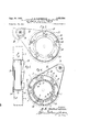
- FIG. 3 shows the infeed side of a rotor of a debarking machine of rotary-ring type, having swingable debarking tools
- FIG. 4 shows the opposite side of said rotor illustrat ing the arrangement according to the invention for actuating the tools
- FIG. 5 is a view of the rotor seen from the side.
- a cylindrical body or housing is designated by 1, At one end of this cylinder there is fixed by welding an end plate 2, into which opens a pipe 3 for supplying a liquid or gaseous pressure medium, preferably compressed air. At the opposite end of this cylinder 1 is detachably fixed an end plate 4.
- the cylinder 1 is divided into two chambers by means of a detachable partition Wall 5, which at its circumference is provided with a groove into which is placed an O-ring 6 of synthetic rubber to guarantee tightening between these two chambers.
- a piston 7 is displaceable in each cylinder 1, and at the circumference of each piston 7 there is an O-ring 8 of synthetic rubber.
- each piston 7 is welded a centrally arranged hollow piston rod 9, which with itsfree end bears against another piston 10 in the cylinder 1, and at the circumference of each piston 10 there is an O-ring 11 of synthetic rubber acting as a seal.
- an O-ring 11 of synthetic rubber acting as a seal.
- the partition wall 5 which is provided with a hole for the passage of the piston rod 9 there is provided an O-ring 13 of synthetic rubber sealing against the exterior of piston rod 9.
- At the free end of the pipe 9 there are four radial holes 14 for the passage of the pressure medium to the space 15 between the piston 10 and the partition wall 5.
- the cross sectional area of the central opening 21 is greater than the cross sectional area of piston rod 22 so as to accommodate the angular deviation or movement of the rod with respect to the piston and cylinder.
- the free end of the rod 22 is fork-shaped with two shanks 23 in which is journalled an arm 24 by means of a bolt 25.
- the arm 24 is fixed to a shaft 26, which is journalled in the rotor 27 and on its opposite end carries a swingable arm 28, the free end of which is shaped as a debarking tool.
- Reference character 29 designates a cushion of rubber against which each arm 30 abuts when the tool arm 28 swings downwards toward the center line of the rotor.
- the end plate of the cylinder 1 is provided with a flange 31 for fastening of each cylinder to the end wall of the rotor 27.
- This rotor is driven by a belt means 32 trained over a pulley means 34 driven by an electric motor 33 (indicated by dotted lines).
- the rotor 27 is journalled on bearing rings 51, 52 in a stator 35 of which a part is illustrated in said figure.
- the compressed air is supplied by means of a pipe 36 in the stator 35, the free end of said pipe opening in a stationary ring shaped member 37 of inelastic material having good frictional properties.
- This ring shaped member 37 is in contact by one of its sides with a radial flange 38 of a ring shaped member 39 fixed to and rotating with the rotor 27 by stop pin means 53, while the opposite side of the stationary member 37 is in contact with a ring shaped member 40 axially displaceable on the ring shaped member 39.
- An O-riug 42 serves as a sealing means.
- the axially movable member 40 is held pressed against the member 37 by means of an O-ring 43 of synthetic rubber actuated by an axially displaceable ring shaped member 41, whereby the member 41 in its turn is axially adjusted by means of a member 44 threaded on the member 39.
- the pressure air passes through a channel 45 provided in the flange 38 of the ring shaped member 39 to an outlet 46 for communicating with the pipe 3.
- the details of the sealing means and supply arrangement for feeding air to the tubes 3 for the respective cylinders are further disclosed in Patent No. 2,945,706, dated July 19, 1960.
- the stator 35 is provided with an apertures to accommodate a pin means 47 shown diagrammatically.
- the outer face of the ring 44 is provided with a bore which when spaced in alignment with the aperture in the stator will receive the pin means 47.
- the ring 44 is then held fast and the rotor turned by hand to effect axial movement of ring 44 relative to ring member 39 so as to compress the O-ring 43.
- the object of the compression spring 20 is as mentioned above to more or less relieve or unload the actuating pressure on the debarking tool when changing over to debarking of logs having smaller dimensions and for rapidly bringing the tools to a position to expose a maximum gap when shutting off the pressure medium, which is very advantageous also when the debarking machine is brought to a standstill.
- the arrangement with two pistons located in line with each other results in almost double the actuating force of one piston of same diameter, which, due to the limited space available for the cylinder, is particularly favorable.
- a frame a rotor carried by such frame, a plurality of debarking tools mounted on the infeed side of such rotor for swinging movement about axes parallel to the axis of the rotor, lever means connected to the tools and means for moving such lever means in opposite directions to elfect inward and outward movement of the tools with respect to the axis of the rotor
- lever means connected to the tools and means for moving such lever means in opposite directions to elfect inward and outward movement of the tools with respect to the axis of the rotor
- each lever means a cylinder including opposite ends, a partition within the cylinder dividing the cylinder into two-piston-accommodating chambers, means for admitting fluid under pressure into the chamber at one end of the cylinder, the other end of the cylinder having an opening therethrough, a first piston within the chamber at said one end of the cylinder, at second piston within the other chamber, said partition having an opening therein, said second piston having a head facing said last-menti
- a rotor structure including an annular member disposed perpendicular to the axis of the rotor, a plurality of tool-carrying shafts carried by such annular member and having their axes parallel to the axis of the rotor, debarking tool means carried by such shafts on the infeed side of said member, lever means connected to said shafts on the side of said annular member opposite said debarking tool means, and means for moving such lever means in opposite directions to effect inward and outward movement of the tools with respect to the axis of the rotor comprising for each lever means a cylinder including opposite ends, a partition within the cylinder dividing the cylinder into two piston-accommodating chambers, means for admitting fluid under pressure into the chamber at one end of the cylinder, the other end of the cylinder having an opening therethrough, a first piston within the chamber at said one end of the cylinder,
Description
Sept. 11, 1962 A. E. ANDERSSON 3,053,294
FLUID PRESSURE OPERATED MECHANISM FOR ACTUATING THE DEBARKING TOOLS OF A DEBARKING MACHINE OF THE ROTARY-RING TYPE Filed Oct. 26, 1959 3 Sheets-Sheet l IN V EN TOR. E flzzderssojv 3,053,294 UATING ANDERSSO RATED MECHANISM FOR ACT DEBARKING TOOLS OF A DEBARKING CHINE OF THE ROTARY-RING TYPE Sept. 11, 1962 FLUID PRESSURE OPE THE 3 Sheets-Sheet 2 Filed Oct. 26, 1959 R gw 7 INVENTOR. ,ez-asaow Sept 11, 1962 A. E. ANDERSSON 3,053,294
FLUID PRESSURE OPERATED MECHANISM FOR ACTUATING THE DEBARKING TOOLS OF A DEBARKING MACHINE OF THE ROTARY-RING TYPE Filed Oct. 26, 1959 3 Sheets-Sheet 3 3,053 294 FLUID PRESSURE ()PERATED MECHANISM FOR ACTUATING THE DEBARKING TOOLS OF A DEBARKING MACHINE OF THE ROTARY- RING TYPE Axel Erland Andersson, Gavle, Sweden, Hans Lindherg,
administrator of said Axel Erland Andersson, deceased Filed Oct. 26, 1959, Ser. No. 848,630 Claims priority, application Sweden Jan. 24, 1959 2 Claims. (Cl. 144-208) The present invention relates to improvements in fluid pressure operated mechanisms for actuating the debarking tools of a debarking machine of the rotary ring type.
During the operation of such debarking machines it is desirable that the actuating pressure on the debarking tools be rapidly relieved or unloaded when changing from debarking large diameter logs to debarking logs of smaller dimension and to permit the arms carrying the debarking tools to be rapidly opened to provide a maximum gap when shutting ofi the liquid or gaseous pressure medium.
In such machines it has further proved to be very difficult, in certain cases, to attain the required actuating force within the space available for the cylinders of the pi tons actuating the tools.
By the arrangement according to the present invention these demands have been carried out in an effective manner and the invention is principally characterized thereby, that the cylinder for each debarking tool, fed by the liquid or gaseous pressure medium, is provided with at least two cooperating pistons located in line with each other, each of said pistons being actuated by the pres sure medium, the pressure action of said pistons being counteracted by a compression spring acting against one of said pistons.
Other characteristic features of the invention will be further explained in connection with the description of an embodiment of the arrangement illustrated on the attached drawings, in which:
FIG. 1 shows a longitudinal sectional elevation of an embodiment of the invention,
FIG. 2 illustrates the arrangement for feeding air under pressure to the cylinder arrangement shown in FIG. 1,
FIG. 3 shows the infeed side of a rotor of a debarking machine of rotary-ring type, having swingable debarking tools,
FIG. 4 shows the opposite side of said rotor illustrat ing the arrangement according to the invention for actuating the tools,
FIG. 5 is a view of the rotor seen from the side.
In the embodiment illustrated in FIG. 1 a cylindrical body or housing is designated by 1, At one end of this cylinder there is fixed by welding an end plate 2, into which opens a pipe 3 for supplying a liquid or gaseous pressure medium, preferably compressed air. At the opposite end of this cylinder 1 is detachably fixed an end plate 4. The cylinder 1 is divided into two chambers by means of a detachable partition Wall 5, which at its circumference is provided with a groove into which is placed an O-ring 6 of synthetic rubber to guarantee tightening between these two chambers. A piston 7 is displaceable in each cylinder 1, and at the circumference of each piston 7 there is an O-ring 8 of synthetic rubber. To each piston 7 is welded a centrally arranged hollow piston rod 9, which with itsfree end bears against another piston 10 in the cylinder 1, and at the circumference of each piston 10 there is an O-ring 11 of synthetic rubber acting as a seal. Between the piston 7 and the partition wall 5 there are provided several holes 12 in the cylinder 1 intended for the draining of the right-hand 3,953,294 Patented Sept. 11, 1962 chamber, FIGURE 1. In the partition wall 5, which is provided with a hole for the passage of the piston rod 9 there is provided an O-ring 13 of synthetic rubber sealing against the exterior of piston rod 9. At the free end of the pipe 9 there are four radial holes 14 for the passage of the pressure medium to the space 15 between the piston 10 and the partition wall 5. Between the opposite end of the rod 9 and the end plate 2 there is a space 16 which permits the supply of pressure medium to the chamber 17 between the end plate 2 and the piston 7. The face of piston 10 remote from rod 9 is provided with a spherical depression 18 serving as bearing for a washer 19 complementarily shaped to fit in said depression, against which bares a compression spring 20, the opposite end of which is biased against the inner face of end plate 4. In this end plate there is a central hole 21, through which a piston rod 22, which is welded to the washer 19, can freely move. The spherical contact of the washer 19 with the piston 10 permits a certain angular deviation of the rod 22 and is replacing a piston pivot. As is clear from the drawing the cross sectional area of the central opening 21 is greater than the cross sectional area of piston rod 22 so as to accommodate the angular deviation or movement of the rod with respect to the piston and cylinder. The free end of the rod 22 is fork-shaped with two shanks 23 in which is journalled an arm 24 by means of a bolt 25. The arm 24 is fixed to a shaft 26, which is journalled in the rotor 27 and on its opposite end carries a swingable arm 28, the free end of which is shaped as a debarking tool. Reference character 29 designates a cushion of rubber against which each arm 30 abuts when the tool arm 28 swings downwards toward the center line of the rotor. The end plate of the cylinder 1 is provided with a flange 31 for fastening of each cylinder to the end wall of the rotor 27. This rotor is driven by a belt means 32 trained over a pulley means 34 driven by an electric motor 33 (indicated by dotted lines).
As to be seen from FIG. 2 the rotor 27 is journalled on bearing rings 51, 52 in a stator 35 of which a part is illustrated in said figure. The compressed air is supplied by means of a pipe 36 in the stator 35, the free end of said pipe opening in a stationary ring shaped member 37 of inelastic material having good frictional properties. This ring shaped member 37 is in contact by one of its sides with a radial flange 38 of a ring shaped member 39 fixed to and rotating with the rotor 27 by stop pin means 53, while the opposite side of the stationary member 37 is in contact with a ring shaped member 40 axially displaceable on the ring shaped member 39. An O-riug 42 serves as a sealing means. The axially movable member 40 is held pressed against the member 37 by means of an O-ring 43 of synthetic rubber actuated by an axially displaceable ring shaped member 41, whereby the member 41 in its turn is axially adjusted by means of a member 44 threaded on the member 39. From the pipe 36 the pressure air passes through a channel 45 provided in the flange 38 of the ring shaped member 39 to an outlet 46 for communicating with the pipe 3. The details of the sealing means and supply arrangement for feeding air to the tubes 3 for the respective cylinders are further disclosed in Patent No. 2,945,706, dated July 19, 1960. To efifect actual adjustment of the ring shaped member 44 the stator 35 is provided with an apertures to accommodate a pin means 47 shown diagrammatically. The outer face of the ring 44 is provided with a bore which when spaced in alignment with the aperture in the stator will receive the pin means 47. The ring 44 is then held fast and the rotor turned by hand to effect axial movement of ring 44 relative to ring member 39 so as to compress the O-ring 43.
The object of the compression spring 20 is as mentioned above to more or less relieve or unload the actuating pressure on the debarking tool when changing over to debarking of logs having smaller dimensions and for rapidly bringing the tools to a position to expose a maximum gap when shutting off the pressure medium, which is very advantageous also when the debarking machine is brought to a standstill. The arrangement with two pistons located in line with each other results in almost double the actuating force of one piston of same diameter, which, due to the limited space available for the cylinder, is particularly favorable. By arranging still more independent pistons in line with each other and separately actuating them by the pressure medium it is evident that the effect can be further increased while maintaining same diameter of the cylinders, whereby the supply of the pressure medium can be made by means of pipes provided on the outside of the cylinders. The invention further contemplates the provision of means cooperably related between the second piston and the second piston rod means 22 permitting limited angular movement of the second piston rod with respect to the second piston.
The embodiment illustrated is to be considered as an example and it is evident that the same can be varied in dilferent ways within the scope of the invention.
What I claim is:
1. In a debarking machine of the type wherein logs are fed axially to and through the machine, a frame, a rotor carried by such frame, a plurality of debarking tools mounted on the infeed side of such rotor for swinging movement about axes parallel to the axis of the rotor, lever means connected to the tools and means for moving such lever means in opposite directions to elfect inward and outward movement of the tools with respect to the axis of the rotor comprising for each lever means a cylinder including opposite ends, a partition within the cylinder dividing the cylinder into two-piston-accommodating chambers, means for admitting fluid under pressure into the chamber at one end of the cylinder, the other end of the cylinder having an opening therethrough, a first piston within the chamber at said one end of the cylinder, at second piston within the other chamber, said partition having an opening therein, said second piston having a head facing said last-mentioned opening, a hollow piston rod extending through and connected to the piston in the chamber at said one end of the cylinder, and also extending away from said one end of the cylinder through the opening in the partition and terminating in a free end bearing against the head of the second piston, said hollow piston rod having openings therein adjacent its free end whereby fluid under pressure can flow through the hollow piston rod and act directly on said second piston, said second piston having a spherical depression in the face thereof remote from said one end of the cylinder, a complementary shaped washer seated in said depression, piston rod means connected to said washer and extending away from said second piston through the opening in the other end of said cylinder and connected to said lever means exteriorly of said cylinder, and spring means biased directly between said other end of the cylinder and said washer, whereby fluid under pressure moves said first piston and said second piston and said hollow piston rod in its movement applies pressure to the head of said second piston so that the force of both pistons is applied to said lever means to swing said tools inwardly and apply log debarking pressure thereto and when fluid pressure is relieved said spring means moves said second piston which in turn moves said hollow piston rod and thus said first piston towards said one end of the cylinder to import opposite movement to said lever means to swing said 4- tools outwardly to expose a maximum opening in the rotor.
2. In a debarking machine of the type in which logs are fed axially to and through the machine for debarking purposes, a rotor structure including an annular member disposed perpendicular to the axis of the rotor, a plurality of tool-carrying shafts carried by such annular member and having their axes parallel to the axis of the rotor, debarking tool means carried by such shafts on the infeed side of said member, lever means connected to said shafts on the side of said annular member opposite said debarking tool means, and means for moving such lever means in opposite directions to effect inward and outward movement of the tools with respect to the axis of the rotor comprising for each lever means a cylinder including opposite ends, a partition within the cylinder dividing the cylinder into two piston-accommodating chambers, means for admitting fluid under pressure into the chamber at one end of the cylinder, the other end of the cylinder having an opening therethrough, a first piston within the chamber at said one end of the cylinder, a second piston within the other chamber, said partition having an opening therein, said second piston having a head facing said last-mentioned opening, a hollow piston rod extending through and connected to the piston in the chamber at said one end of the cylinder, and also extending away from said one end of the cylinder through the opening in the partition and terminating in a free end bearing against the head of the second piston, said hollow piston rod having openings therein adjacent its free end whereby fluid under pressure can flow through the hollow piston rod and act directly on said second piston, second piston rod means, means co-operatively related between said second piston and said second piston rod means permitting limited angular movement of said second piston rod means with respect to said second piston, said second piston rod means including a portion extending away from said second piston through the opening in the other end of said cylinder and connected to said lever means exteriorly of said cylinder, said opening in the other end of the cylinder having greater cross sectional area than the cross sectional area of said second piston rod means so as to accommodate, said limited angular movement, and spring means biased between said other end of the cylinder and the means cooperatively related between said second piston and said second piston rod means whereby fluid under pressure moves said first piston and said second piston and said hollow piston rod in its movement applies pressure to the head of said second piston so that the force of both pistons is applied to said lever means to swing said tools inwardly and apply log debarking pressure thereto and when fluid pressure is relieved said spring means moves said second piston which in turn moves said hollow piston rod and thus said first piston towards said one end of the cylinder to impart opposite movement to said lever means to swing said tools outwardly to expose a maximum opening in the rotor.
References Cited in the file of this patent UNITED STATES PATENTS 2,402,212 Shatf June 18, 1946 2,692,623 Lefller Oct. 26, 1954 2,788,034 Brundell et al Apr. 9, 1957 2,798,519 Hansel July 9, 1957 2,802,495 Nicholson Aug. 13, 1957 2,888,966 Morgan et a1. June 2, 1959 2,901,888 Swift Sept. 1, 1959 2,960,128 Uhlenkott Nov. 15, 1960 FOREIGN PATENTS 161,883 Sweden Jan. 14,1958
Applications Claiming Priority (1)
| Application Number | Priority Date | Filing Date | Title |
|---|---|---|---|
| SE3053294X | 1959-01-24 |
Publications (1)
| Publication Number | Publication Date |
|---|---|
| US3053294A true US3053294A (en) | 1962-09-11 |
Family
ID=20428352
Family Applications (1)
| Application Number | Title | Priority Date | Filing Date |
|---|---|---|---|
| US848630A Expired - Lifetime US3053294A (en) | 1959-01-24 | 1959-10-26 | Fluid pressure operated mechanism for actuating the debarking tools of a debarking machine of the rotaryring type |
Country Status (1)
| Country | Link |
|---|---|
| US (1) | US3053294A (en) |
Cited By (15)
| Publication number | Priority date | Publication date | Assignee | Title |
|---|---|---|---|---|
| US3137329A (en) * | 1962-10-18 | 1964-06-16 | Ederer Corp | Ring barker with pneumatic pressure operated debarking arms |
| US3196912A (en) * | 1961-05-10 | 1965-07-27 | Soderhamns Verkst Er Ab | Controlling mechanisms for the tools in a log debarking machine |
| US3361168A (en) * | 1965-11-30 | 1968-01-02 | Black Clawson Co | Log barker |
| US3667517A (en) * | 1970-09-02 | 1972-06-06 | Black Clawson Co | Log barker |
| US4087074A (en) * | 1976-11-26 | 1978-05-02 | The Parker & Harper Mfg. Co., Inc. | Spring return valve actuator |
| WO1984001322A1 (en) * | 1982-09-30 | 1984-04-12 | James Henry Hutson | Hydraulic fed log debarker |
| EP0203794A1 (en) * | 1985-05-29 | 1986-12-03 | DAVY McKEE (POOLE) LIMITED | Hydraulic RAM assembly |
| US4657047A (en) * | 1984-12-10 | 1987-04-14 | Nordson Corporation | Modular color changers with improved valves and manifolds |
| US4673012A (en) * | 1985-12-06 | 1987-06-16 | Brien Jr John A O | Tool tensioning device for debarking machine |
| US4702277A (en) * | 1985-05-01 | 1987-10-27 | Veriflo Corporation | Cylinder valve-regulator |
| US4830072A (en) * | 1988-08-02 | 1989-05-16 | Brunette Machine Works, Ltd. | Air seal for rotary log debarker |
| US6314862B1 (en) * | 2000-01-24 | 2001-11-13 | Retterer Manufacturing Co., Inc. | Combination cylinder and pistons |
| US6651709B1 (en) | 2002-09-11 | 2003-11-25 | Cae Wood Products, G.P. | Retractable debarking apparatus |
| US20060169359A1 (en) * | 2005-01-28 | 2006-08-03 | Carmanah Design And Manufacturing Inc. | Debarking apparatus with adjustable rate of debarking |
| WO2016199073A1 (en) | 2015-06-09 | 2016-12-15 | Kongsberg Inc. | Actuator assembly driven by a fluid and a method of operating the same |
Citations (8)
| Publication number | Priority date | Publication date | Assignee | Title |
|---|---|---|---|---|
| US2402212A (en) * | 1942-08-12 | 1946-06-18 | Keller Tool Co | Operation controlling means for pressure fluid actuated tools |
| US2692623A (en) * | 1951-03-22 | 1954-10-26 | Svenska Cellulosa Ab | Debarking machine having bark-removing members yieldably connected to centrifugally-actuated weights |
| US2788034A (en) * | 1954-06-28 | 1957-04-09 | Soderhamns Verkst Er Ab | Rotary ring-type debarker, including means for disintegrating slivers of bark |
| US2798519A (en) * | 1956-05-10 | 1957-07-09 | Hansel Sydney | Rotary debarker having pneumatically operable bark-removing tools |
| US2802495A (en) * | 1954-02-01 | 1957-08-13 | Thomas W Nicholson | Swiveled-scraper-plate rotary-ring log barkers |
| US2888966A (en) * | 1955-02-14 | 1959-06-02 | Continental Gin Co | Rotating air seal |
| US2901888A (en) * | 1957-09-20 | 1959-09-01 | Int Harvester Co | Multi-piston servo-motor |
| US2960128A (en) * | 1958-12-29 | 1960-11-15 | John J Uhlenkott | Pole-debarking machine |
-
1959
- 1959-10-26 US US848630A patent/US3053294A/en not_active Expired - Lifetime
Patent Citations (8)
| Publication number | Priority date | Publication date | Assignee | Title |
|---|---|---|---|---|
| US2402212A (en) * | 1942-08-12 | 1946-06-18 | Keller Tool Co | Operation controlling means for pressure fluid actuated tools |
| US2692623A (en) * | 1951-03-22 | 1954-10-26 | Svenska Cellulosa Ab | Debarking machine having bark-removing members yieldably connected to centrifugally-actuated weights |
| US2802495A (en) * | 1954-02-01 | 1957-08-13 | Thomas W Nicholson | Swiveled-scraper-plate rotary-ring log barkers |
| US2788034A (en) * | 1954-06-28 | 1957-04-09 | Soderhamns Verkst Er Ab | Rotary ring-type debarker, including means for disintegrating slivers of bark |
| US2888966A (en) * | 1955-02-14 | 1959-06-02 | Continental Gin Co | Rotating air seal |
| US2798519A (en) * | 1956-05-10 | 1957-07-09 | Hansel Sydney | Rotary debarker having pneumatically operable bark-removing tools |
| US2901888A (en) * | 1957-09-20 | 1959-09-01 | Int Harvester Co | Multi-piston servo-motor |
| US2960128A (en) * | 1958-12-29 | 1960-11-15 | John J Uhlenkott | Pole-debarking machine |
Cited By (20)
| Publication number | Priority date | Publication date | Assignee | Title |
|---|---|---|---|---|
| US3196912A (en) * | 1961-05-10 | 1965-07-27 | Soderhamns Verkst Er Ab | Controlling mechanisms for the tools in a log debarking machine |
| US3137329A (en) * | 1962-10-18 | 1964-06-16 | Ederer Corp | Ring barker with pneumatic pressure operated debarking arms |
| US3361168A (en) * | 1965-11-30 | 1968-01-02 | Black Clawson Co | Log barker |
| US3667517A (en) * | 1970-09-02 | 1972-06-06 | Black Clawson Co | Log barker |
| US4087074A (en) * | 1976-11-26 | 1978-05-02 | The Parker & Harper Mfg. Co., Inc. | Spring return valve actuator |
| WO1984001322A1 (en) * | 1982-09-30 | 1984-04-12 | James Henry Hutson | Hydraulic fed log debarker |
| US4522242A (en) * | 1982-09-30 | 1985-06-11 | Hutson James Henry | Hydraulic fed log debarker |
| US4830055A (en) * | 1984-12-10 | 1989-05-16 | Nordson Corporation | Circulating and dead end color changer with improved valves and manifolds |
| US4657047A (en) * | 1984-12-10 | 1987-04-14 | Nordson Corporation | Modular color changers with improved valves and manifolds |
| US4702277A (en) * | 1985-05-01 | 1987-10-27 | Veriflo Corporation | Cylinder valve-regulator |
| EP0203794A1 (en) * | 1985-05-29 | 1986-12-03 | DAVY McKEE (POOLE) LIMITED | Hydraulic RAM assembly |
| US4673012A (en) * | 1985-12-06 | 1987-06-16 | Brien Jr John A O | Tool tensioning device for debarking machine |
| US4830072A (en) * | 1988-08-02 | 1989-05-16 | Brunette Machine Works, Ltd. | Air seal for rotary log debarker |
| US6314862B1 (en) * | 2000-01-24 | 2001-11-13 | Retterer Manufacturing Co., Inc. | Combination cylinder and pistons |
| US6651709B1 (en) | 2002-09-11 | 2003-11-25 | Cae Wood Products, G.P. | Retractable debarking apparatus |
| US20060169359A1 (en) * | 2005-01-28 | 2006-08-03 | Carmanah Design And Manufacturing Inc. | Debarking apparatus with adjustable rate of debarking |
| WO2016199073A1 (en) | 2015-06-09 | 2016-12-15 | Kongsberg Inc. | Actuator assembly driven by a fluid and a method of operating the same |
| CN107636364A (en) * | 2015-06-09 | 2018-01-26 | 康斯博格股份有限公司 | By fluid-operated actuator and its operating method |
| EP3308058A4 (en) * | 2015-06-09 | 2019-02-20 | Kongsberg Inc. | Actuator assembly driven by a fluid and a method of operating the same |
| CN107636364B (en) * | 2015-06-09 | 2019-06-14 | 康斯博格股份有限公司 | By fluid-operated actuator and its operating method |
Similar Documents
| Publication | Publication Date | Title |
|---|---|---|
| US3053294A (en) | Fluid pressure operated mechanism for actuating the debarking tools of a debarking machine of the rotaryring type | |
| US5782586A (en) | Spindle unit for machine tools | |
| US4508357A (en) | Power-operated chuck for turning machines | |
| US3186281A (en) | Knife holder of roller cutting machines | |
| US5255604A (en) | Pressure fluid supply valve assembly | |
| JPS5920376B2 (en) | Assembly for preventing dust leakage in internal rotary mixers | |
| US4106880A (en) | Portable field machine for cutting, grinding and lapping valve seats | |
| US3190327A (en) | Log barker with vane-actuated barking arms | |
| US2501387A (en) | Veneer lathe | |
| US3137329A (en) | Ring barker with pneumatic pressure operated debarking arms | |
| US1065332A (en) | Crusher. | |
| CA2067051C (en) | Rotary log debarker with improved air management system | |
| US2699084A (en) | Machine tool for machining brake drums and the like | |
| US4673012A (en) | Tool tensioning device for debarking machine | |
| US2959202A (en) | Lathe chucks | |
| US3236273A (en) | Barker | |
| US2970578A (en) | Oil pressure motor | |
| US2981201A (en) | Piston machine | |
| US4372355A (en) | Wood turning lathe apparatus | |
| US2372721A (en) | Portable hydraulic riveter | |
| US3468551A (en) | Chuck | |
| US2911765A (en) | Refacing machine | |
| US2870706A (en) | Pressure means for rotary printing machines | |
| US5941146A (en) | Work spindle | |
| US2730077A (en) | Improved rotary compressed-air operated motor |