US3075718A - Web splicing machine - Google Patents
Web splicing machine Download PDFInfo
- Publication number
- US3075718A US3075718A US86246A US8624661A US3075718A US 3075718 A US3075718 A US 3075718A US 86246 A US86246 A US 86246A US 8624661 A US8624661 A US 8624661A US 3075718 A US3075718 A US 3075718A
- Authority
- US
- United States
- Prior art keywords
- web
- nip rolls
- shafts
- actuated
- cam shafts
- Prior art date
- Legal status (The legal status is an assumption and is not a legal conclusion. Google has not performed a legal analysis and makes no representation as to the accuracy of the status listed.)
- Expired - Lifetime
Links
Images
Classifications
-
- B—PERFORMING OPERATIONS; TRANSPORTING
- B65—CONVEYING; PACKING; STORING; HANDLING THIN OR FILAMENTARY MATERIAL
- B65H—HANDLING THIN OR FILAMENTARY MATERIAL, e.g. SHEETS, WEBS, CABLES
- B65H19/00—Changing the web roll
- B65H19/10—Changing the web roll in unwinding mechanisms or in connection with unwinding operations
- B65H19/18—Attaching, e.g. pasting, the replacement web to the expiring web
- B65H19/1857—Support arrangement of web rolls
- B65H19/1873—Support arrangement of web rolls with two stationary roll supports carrying alternately the replacement and the expiring roll
-
- B—PERFORMING OPERATIONS; TRANSPORTING
- B65—CONVEYING; PACKING; STORING; HANDLING THIN OR FILAMENTARY MATERIAL
- B65B—MACHINES, APPARATUS OR DEVICES FOR, OR METHODS OF, PACKAGING ARTICLES OR MATERIALS; UNPACKING
- B65B41/00—Supplying or feeding container-forming sheets or wrapping material
- B65B41/12—Feeding webs from rolls
-
- B—PERFORMING OPERATIONS; TRANSPORTING
- B65—CONVEYING; PACKING; STORING; HANDLING THIN OR FILAMENTARY MATERIAL
- B65H—HANDLING THIN OR FILAMENTARY MATERIAL, e.g. SHEETS, WEBS, CABLES
- B65H19/00—Changing the web roll
- B65H19/10—Changing the web roll in unwinding mechanisms or in connection with unwinding operations
- B65H19/18—Attaching, e.g. pasting, the replacement web to the expiring web
- B65H19/1805—Flying splicing, i.e. the expiring web moving during splicing contact
- B65H19/1826—Flying splicing, i.e. the expiring web moving during splicing contact taking place at a distance from the replacement roll
- B65H19/1836—Flying splicing, i.e. the expiring web moving during splicing contact taking place at a distance from the replacement roll the replacement web being accelerated or running prior to splicing contact
-
- B—PERFORMING OPERATIONS; TRANSPORTING
- B65—CONVEYING; PACKING; STORING; HANDLING THIN OR FILAMENTARY MATERIAL
- B65H—HANDLING THIN OR FILAMENTARY MATERIAL, e.g. SHEETS, WEBS, CABLES
- B65H2301/00—Handling processes for sheets or webs
- B65H2301/40—Type of handling process
- B65H2301/46—Splicing
- B65H2301/462—Form of splice
- B65H2301/4621—Overlapping article or web portions
-
- B—PERFORMING OPERATIONS; TRANSPORTING
- B65—CONVEYING; PACKING; STORING; HANDLING THIN OR FILAMENTARY MATERIAL
- B65H—HANDLING THIN OR FILAMENTARY MATERIAL, e.g. SHEETS, WEBS, CABLES
- B65H2301/00—Handling processes for sheets or webs
- B65H2301/40—Type of handling process
- B65H2301/46—Splicing
- B65H2301/463—Splicing splicing means, i.e. means by which a web end is bound to another web end
- B65H2301/4631—Adhesive tape
-
- B—PERFORMING OPERATIONS; TRANSPORTING
- B65—CONVEYING; PACKING; STORING; HANDLING THIN OR FILAMENTARY MATERIAL
- B65H—HANDLING THIN OR FILAMENTARY MATERIAL, e.g. SHEETS, WEBS, CABLES
- B65H2301/00—Handling processes for sheets or webs
- B65H2301/40—Type of handling process
- B65H2301/46—Splicing
- B65H2301/464—Splicing effecting splice
- B65H2301/46414—Splicing effecting splice by nipping rollers
Definitions
- FIGB 241 [eh i 5 El 0 a f d IIO% 2 2 2 c M 0 2 I ⁇ M ⁇ 7 M r54 m4) 4 ww nw 4 e E Q 9 6 1 x 21m A 82 x. 64 x MIA- ⁇ 2 R m v mm L m W5 D R A H l R ATTORNEYS Uite
- This invention relates to web joining apparatus or splicers, as they are called, and more particularly to splicers for joining webs in motion on wrapping machines or the like.
- This application is a continuationin-part of my prior and copending application Serial No. 59,017, filed on September 28, 1960, now abandoned.
- Still another conventional drawback States Patent has to do with the length of overlap or double web thickness which follows the splice. As packages are wrapped in a wrapping machine, the web must be continuously cut off along the line between the printed patterns on the face of the web, and since this cutting operation also must be performed on the fly and preferably with a serrated type of knife edge, a double web is very difiicult to cut and sometimes spells the difference between success and failure of the splicer.
- Another object of my invention is to provide a splicer which accomplishes the foregoing object, and also in which the trailing end of the depleting web does not tend to shift after it breaks away from its core so that a uniform splice can be made without uneven tensions on the web.
- Another object is to provide mechanism in conjunction with the foregoing which also applies a uniform pressure in the splicing zone with a minimum of shearing strain on the web.
- Still another object of my invention is to provide such a splicer in which the overlap of two layers of web material at the point of splicing is held to a minimum and ends short of the end of a single printed pattern on the face of the web.
- Another feature of my invention is the fact that the splicing nip created between the rolls as they are brought together is extremely uniform and applies a tight grip along a narrow line extending entirely across the web. Also since the rolls are both free to turn, the nip virtually eliminates shearing stresses previously encountered with the friction pad type of arrangement employed in conventional splicers.
- Another feature of my invention in conjunction with the foregoing features is the provision of mechanism for sensing a drop in tension in the depleting web together with operation of a knife simultaneously with a splicing operation to cut off the trailing end of the depleting web.
- the knife is located very close to the splicing zone and in this way I am able to completely avoid the double thickness or overlapping layer of web material in the area where the knife in the wrapping machine must cut the web. Also by cutting off the final portion of the web, I avoid any necessity for making the splice in an area of the web which might include a jagged tear or trailing end of cardboard brought with the web from the core upon which the web is wound.
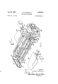
- FIG. 1 is a perspective and somewhat exploded view of the elements of the machine with the shaft supporting frame structure removed for clarity;
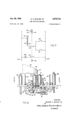
- FIG. 2 is a plan view of the lower righthand end of the elements shown in FIG. 1 with the addition of some elements not shown in FIG. 1;
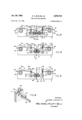
- FIG. 3 is a cross-sectional view taken along the line 33 of FIG. 2;
- FIG. 4 is a view similar to FIG. 3 but with the nip rolls in engaging position at the start of the splicing operation;
- FIG. 5 is a view similar to FIG. 4 showing the subsequent position of the Webs after the running web has been cut;
- FIG. 6 is a perspective view showing the manner of mounting the web cutting elements in the supporting frame
- ⁇ FIG. 7 shows the electrical circuit which starts and stops operation of the splicing elements.
- FIG. 1 there are a pair of spaced supporting frame plates 2 and 4 with their center sections broken away for clarity. These plates support the following elements: a pair of nip rolls 6 and 8, which are rotatably mounted on shafts 10 and '12; a pair of cam shafts 14 and x16; a tape holding bar 18; a cutter bar 20; and a cutter 22.
- the plates also support a pair of sensing devices 24 and 26 which are arranged to actuate switches 28 and 30 under appropriate conditions.
- nip rolls 6 and 8 are normally spaced apart,'as shown in :FIG. 3, the shafts 10 and 12 being positioned in horizontally extending slots in the frames 2 and 4, one slot being shown at 32 in FIG. 3.
- Compressible springs 34 function to hold the shafts and nip rolls apart prior to the splicing operation.
- the tape holding bar 18 has its ends positioned in vertical grooves 136 in the frames 2 and 4, which grooves permit the tape holding bar to be raised to a position in which the pressure sensitive tape may be more readily applied thereto by the operator.
- rollers 38 and 40 On the ends of shafts 18 and 12 are rollers 38 and 40 which cooperate with cams 42and 44 mounted respectively on cam shafts 14 and 16.
- a gear 46 freely rotatable on cam shaft '14, is driven by a direct connection to the web consuming machine which is arranged to rotate the gear 46 one revolution for each cycle of the web consuming machine which may be typically thought of as the wrapping of a product and severance of the web.
- Gear 46 has therein an arcuate' 14 commences.
- cam shaft 16 is caused to rotate simultaneously with cam shaft 14.
- cams 68 and 70 which act in a manner to be explained hereinafter to raise and lower the cutting bar 28 at the same time as the nip rolls 6 and 8- are brought into engagement with each other.
- Adjacent to disc 50 is a wedge 72011 the end of armature 74 of solenoid 76. When the wedge is in extended position, it will act to engage the under side of head 78 of clutch pin 54 to hold the pin out of engagement With slot 48 in gear 46.
- spring 56 can function to drive clutch pin 54 toward gear 46 so that the pin will drop into the slot 48 as soon as rotation of gear 46 brings the two into alignment. Since gear 46 rotates in a fixed relation to the cycle of the web consuming machine, this means that the cam shaft 14 can only be driven, and the splicing action can only take place at a single point in the cycle of the web consuming machine. This is important in achieving registration between indicia patterns on the spliced webs, and since this point can be selected at will, it permits the operator to make sure that the splicing tape will avoid contact with the web cutting knife in the consuming machine.
- Solenoid 76 is actuated by the closing of switch 30 upon movement of sensing device 26. This device rests continuously on the running web 80 prior to the splicing operation. The ready web is indicated at 82, but the related sensing device 24 is at this time held out of operation by a latch 84 so that switch 28 is immobilized. When conditions are reversed so that web 82 becomes the running web and web 80 the ready web, then latch 84 will be released so that sensing device 24 can rest on web 82 and a latch 86 will be used to hold, sensing device 26 in inoperative condition.
- the running web 89 is shown as passing over an idler roll 88, thence over cutter bar 20 and over the freely rotatable nip roll 8. Thence the running Web passes on to the wrapping machine or other device utilizing the web.
- the stationary ready web 8-2 passes over idler roller 90 and thence over cutter bar 92. It will be noted that there is no cutting knife in position above bar 9'2, as the cooperating cutting knife 22 is only positioned to function with the cutting bar that is currently under the running web, which in this case is bar 20.
- the leading end 94- of ready web 82 is cut off smoothly in a crosswise direction and has attached thereto a transversely extending strip of pressure sensitive tape 96.
- This tape at a position close to end 94, is manually pressed against the tape holding bar 18 in a manner which permits the lower portion 98 of the pressure sensitive tape to extend downwardly to a position directly between the nip rolls 6 and 8.
- Running web 80 which is still beingsteadily drawn to the wrapping machine, now has attached to it at a position near its out tail end 110 and the leading end 94 of ready web 82, the two webs being securely affixed by the pressure sensitive tape 96.
- Cam 44 shown at the right end of cam shaft 16 in FIG. 1, has a second cam face 112 which is designed to cooperate with a switch arm 114. Cam face 112 is so shaped that engagement with arm 114 is made at about the completion of one revolution of the cam shafts.
- FIG. 7 it can be seen that when cam face 112 engages arm 114, which is connected directly to switches 186 and 116, the effect is to open switch 186 and close switch 116.
- Opening of switch 186 de-energizes solenoid 76, causing armature 74 to be driven by a spring 118 toward disc 50 so that the Wedge 72 enters under head 78 of pin 54-, causing immediate withdrawal of the pin from slot 48.
- This disengagement results in immediate cessation of rotation of earn shafts 14 and 16 and their related cams.
- the earns 42 and 44 and 68 and 70 at the time they come to rest will be in the positions shown in FiG. 3, at which time the nip roll 6 and 8 are separated by springs 34 and the cutting bars 92 and 20 will be in their downmost positions.
- the web 82 which was previously the ready web, will now be the running web, running freely over idler 98, cutting bar 92 and the freely rotatable nip roll 6 which will be in the separated position shown in FIG. 3.
- the next step is the positioning by the operator of a new roll of web material which will be set up in place of the now exhausted running web 80 to be spliced to the tail end of the now running web 82.
- the cutter 22 (see FIG. 6), which had been maintained in the upper end of a recessed slot 120 by latches 122 mounted on frame plates 2 and 4, is upon release of latches '122, removed from its position over cutter bar 20 and placed in the upper end of corresponding slot 124 to be latched in position by latches 126'.
- the new web that replaces the old running web 80 will then have afi'ixed to its leading end a piece of pressure sensitive tape which will be affixed to the tape holding bar 18 in a manner similar to but reversed from that shown with respect to tape 96 in FIG. 3.
- Sensing device 24 will be released by the operator to rest on top of the now running web 82, where it will be ready to close switch 28 upon the slackening of web 82, which occurs when this web becomes exhausted.
- Sensing device 26 is now lifted by the operator and latched in raised position by latch 86, the raised position being indicated at 26' in FIG. 3.
- an automatic web splicer a pair of normally spaced nip rolls, a pair of cam shafts adjacent said nip rolls, cams on said shafts which upon rotation of said shafts engage said nip rolls and move them into engagement, means for driving said cam shafts through a single revolution only, said means comprising a sensing device actuated by a running web that is passing over one of said nip rolls, an electric circuit including a switch actuated by said device and a solenoid, a continuously rotating prime mover, a clutch actuated by said solenoid for engaging said cam shafts with said prime mover, and other means actuated by rotation of said cam shafts for disconnecting said clutch after one revolution of said cam shafts and when the said cams are in a position permitting separation of said nip rolls, and means for restoring said nip rolls to their normaly spaced position.
- an automatic web splicer associable with a cyclically operating web-consuming machine, a pair of normally spaced nip rolls, a pair of cam shafts adjacent said nip rolls, cams on said shafts which upon rotation of said shafts engage said nip rolls and move them into engagement, means for driving said cam shafts through a single revolution only, said means comprising a sensing device actuated by a running web that is passing over one of said nip rolls, an electric circuit including a switch actuated by said device and a solenoid, a continuously rotating prime mover in synchronism with the web-consuming machine, a clutch actuated by said solenoid for engaging said cam shafts with said prime mover at a predetermined point in the cycle of the web-consuming machine, and other means actuated by rotation of said cam shafts for disconnecting said clutch after one revolution of said cam shafts and when the said cams are in a position permitting separation of said nip rolls, and means for restoring said ni
Description
Jan. 29, 1963 R. A. BUTLER, JR
WEB SPLICING MACHINE 3 Sheets-Sheet 1 Filed Jan. 16, 1961 INVENTOR.
RICHARD A.BUTLER JR f m,m;4,W h-4 ATTORNEYS Jan. 29, 1963 R. A. BUTLER, JR 3,075,713
WEB SPLICING MACHINE Filed Ja .n. 16, 1961 3 Sheets-Sheet 2 FIG.'7
"mm" jib :m as 4 //2 IN VEN TOR.
RICHARD A. BUTLER JR.
.BY fiat, Mk6, M viz Md ATTORNEYS Jan. 29, 1963 R. A. BUTLER, JR.
WEB SPLICING MACHINE 3 Sheets-Sheet 3 Filed Jan. 16, '1961 FIGB 24 241 [eh i 5 El 0 a f d IIO% 2 2 2 c M 0 2 I \M \7 M r54 m4) 4 ww nw 4 e E Q 9 6 1 x 21m A 82 x. 64 x MIA-\ 2 R m v mm L m W5 D R A H l R ATTORNEYS Uite This invention relates to web joining apparatus or splicers, as they are called, and more particularly to splicers for joining webs in motion on wrapping machines or the like. This application is a continuationin-part of my prior and copending application Serial No. 59,017, filed on September 28, 1960, now abandoned.
Conventional splicers have had several serious drawbacks and it is a general object of my invention to provide a splicer which overcomes the same. Among these drawbacks is the fact that conventional splicers usually require mechanisms for shifting the position of the web supply rolls from a stand-by position to an operational position after the splice has been made. This calls for complicated braking arrangements adapted to Work effectively and sensitiviely in several positions and also complicates the location, operation and sensitivity of mechanisms for detecting the depletion or end of the roll. Another drawback incident to the conventional splicing machine designs has to do with accurately positioning and guiding the trailing end of a depleting web after it is no longer under tension. In the conventional splicers once the end of the web breaks away from the core on which it is wrapped, it tends to shift and results in making the splice along an uneven line. This in turn causes uneven stress in the web as the pull of the old web accelerates the new web and its roll, and, when highly sensitive webs are employed, breakage results. Another drawback of conventional splicers has to do with the means for applying pressure to the splicing zone under dynamic conditions. For strong webs of relatively narrow width, a simple splicing pad has been satisfactory, but as the width of the web and the speed of throughput are increased, the splicing pad arrangement becomes less and less satisfactory because it sets up shearing strains in the web due to the fact that it is stationary and the web is traveling. Still another conventional drawback States Patent has to do with the length of overlap or double web thickness which follows the splice. As packages are wrapped in a wrapping machine, the web must be continuously cut off along the line between the printed patterns on the face of the web, and since this cutting operation also must be performed on the fly and preferably with a serrated type of knife edge, a double web is very difiicult to cut and sometimes spells the difference between success and failure of the splicer.
Accordingly, it is a general object of my invention to provide a splicer in which the webs must be fed in either one of two directions so that the operational roll and stand-by roll may be alternated in function without shifting their position, shaft mountings, braking systems, depletion sensers, and/or automatic accelerators.
Another object of my invention is to provide a splicer which accomplishes the foregoing object, and also in which the trailing end of the depleting web does not tend to shift after it breaks away from its core so that a uniform splice can be made without uneven tensions on the web. Another object is to provide mechanism in conjunction with the foregoing which also applies a uniform pressure in the splicing zone with a minimum of shearing strain on the web. Still another object of my invention is to provide such a splicer in which the overlap of two layers of web material at the point of splicing is held to a minimum and ends short of the end of a single printed pattern on the face of the web.
These and other objects are accomplished in a pre- 3,075,718 Patented Jan. 29, 1963 ferred embodiment of my invention by mounting a pair of web rolls for rotation in fixed position on a base. The webs on these rolls are fed into a splicing zone defined between a pair of spaced apart nip rolls with one web being operational, that is, passing over one of the rolls, through the splicing Zone and into the wrapping machine, and with the other web entering from the other direction and being held in ready position in the splicing zone with a piece of pressure sensitive tape on its leading end. With this arrangement, the splice is mad-e by bringing the nip rolls sharply together so as to press the leading end of the stand-by web against the trailing portion of the depleting Web.
It is a feature of my invention that the splicing action of the nip rolls as they are brought together operates equally well whether the new web enters the splicing zone from one side or the other. In this way it is perfectly feasible to mount the web supply rolls in fixed bearings so as to avoid the complexities of movable roll mounts previously employed in conventional splicers. Another feature of my invention emmanating from bringing the nip rolls sharply together is that the depleting web is held against shifting at the instance of application of the splice by the pressure between the rolls. In this way uneven tensions due to shifting of the web are virtually eliminated. Another feature of my invention is the fact that the splicing nip created between the rolls as they are brought together is extremely uniform and applies a tight grip along a narrow line extending entirely across the web. Also since the rolls are both free to turn, the nip virtually eliminates shearing stresses previously encountered with the friction pad type of arrangement employed in conventional splicers. Another feature of my invention in conjunction with the foregoing features is the provision of mechanism for sensing a drop in tension in the depleting web together with operation of a knife simultaneously with a splicing operation to cut off the trailing end of the depleting web. The knife is located very close to the splicing zone and in this way I am able to completely avoid the double thickness or overlapping layer of web material in the area where the knife in the wrapping machine must cut the web. Also by cutting off the final portion of the web, I avoid any necessity for making the splice in an area of the web which might include a jagged tear or trailing end of cardboard brought with the web from the core upon which the web is wound.
Further objects and features of my invention will best be understood and appreciated from a detailed description of a preferred embodiment of my invention, selected for purposes of illustration and shown in the accompanying drawings, in which:
FIG. 1 is a perspective and somewhat exploded view of the elements of the machine with the shaft supporting frame structure removed for clarity;
FIG. 2 is a plan view of the lower righthand end of the elements shown in FIG. 1 with the addition of some elements not shown in FIG. 1;
FIG. 3 is a cross-sectional view taken along the line 33 of FIG. 2;
FIG. 4 is a view similar to FIG. 3 but with the nip rolls in engaging position at the start of the splicing operation;
FIG. 5 is a view similar to FIG. 4 showing the subsequent position of the Webs after the running web has been cut;
FIG. 6 is a perspective view showing the manner of mounting the web cutting elements in the supporting frame;
\FIG. 7 shows the electrical circuit which starts and stops operation of the splicing elements.
Referring to FIG. 1, there are a pair of spaced supporting frame plates 2 and 4 with their center sections broken away for clarity. These plates support the following elements: a pair of nip rolls 6 and 8, which are rotatably mounted on shafts 10 and '12; a pair of cam shafts 14 and x16; a tape holding bar 18; a cutter bar 20; and a cutter 22. The plates also support a pair of sensing devices 24 and 26 which are arranged to actuate switches 28 and 30 under appropriate conditions.
The nip rolls 6 and 8 are normally spaced apart,'as shown in :FIG. 3, the shafts 10 and 12 being positioned in horizontally extending slots in the frames 2 and 4, one slot being shown at 32 in FIG. 3. Compressible springs 34 function to hold the shafts and nip rolls apart prior to the splicing operation.
The tape holding bar 18 has its ends positioned in vertical grooves 136 in the frames 2 and 4, which grooves permit the tape holding bar to be raised to a position in which the pressure sensitive tape may be more readily applied thereto by the operator.
On the ends of shafts 18 and 12 are rollers 38 and 40 which cooperate with cams 42and 44 mounted respectively on cam shafts 14 and 16.
A gear 46, freely rotatable on cam shaft '14, is driven by a direct connection to the web consuming machine which is arranged to rotate the gear 46 one revolution for each cycle of the web consuming machine which may be typically thought of as the wrapping of a product and severance of the web. Gear 46 has therein an arcuate' 14 commences. By means of a pair of sprockets 62 and 64 on the ends of cam shafts 14 and \16 and a cooperatw ing connecting chain 66, cam shaft 16 is caused to rotate simultaneously with cam shaft 14.
Additionally mounted oncam shafts 14 and 16 are cams 68 and 70 which act in a manner to be explained hereinafter to raise and lower the cutting bar 28 at the same time as the nip rolls 6 and 8- are brought into engagement with each other.
Adjacent to disc 50 is a wedge 72011 the end of armature 74 of solenoid 76. When the wedge is in extended position, it will act to engage the under side of head 78 of clutch pin 54 to hold the pin out of engagement With slot 48 in gear 46. When the solenoid is energized to move armature 74 to the right to pull wedge 72 clear of engagement with head 78', then spring 56 can function to drive clutch pin 54 toward gear 46 so that the pin will drop into the slot 48 as soon as rotation of gear 46 brings the two into alignment. Since gear 46 rotates in a fixed relation to the cycle of the web consuming machine, this means that the cam shaft 14 can only be driven, and the splicing action can only take place at a single point in the cycle of the web consuming machine. This is important in achieving registration between indicia patterns on the spliced webs, and since this point can be selected at will, it permits the operator to make sure that the splicing tape will avoid contact with the web cutting knife in the consuming machine.
Solenoid 76 is actuated by the closing of switch 30 upon movement of sensing device 26. This device rests continuously on the running web 80 prior to the splicing operation. The ready web is indicated at 82, but the related sensing device 24 is at this time held out of operation by a latch 84 so that switch 28 is immobilized. When conditions are reversed so that web 82 becomes the running web and web 80 the ready web, then latch 84 will be released so that sensing device 24 can rest on web 82 and a latch 86 will be used to hold, sensing device 26 in inoperative condition.
Referring now to FIGS. 3, 4 and 5, the running web 89 is shown as passing over an idler roll 88, thence over cutter bar 20 and over the freely rotatable nip roll 8. Thence the running Web passes on to the wrapping machine or other device utilizing the web.
On the other side, the stationary ready web 8-2 passes over idler roller 90 and thence over cutter bar 92. It will be noted that there is no cutting knife in position above bar 9'2, as the cooperating cutting knife 22 is only positioned to function with the cutting bar that is currently under the running web, which in this case is bar 20.
The leading end 94- of ready web 82 is cut off smoothly in a crosswise direction and has attached thereto a transversely extending strip of pressure sensitive tape 96. This tape, at a position close to end 94, is manually pressed against the tape holding bar 18 in a manner which permits the lower portion 98 of the pressure sensitive tape to extend downwardly to a position directly between the nip rolls 6 and 8.
As the running web 30 becomes exhausted so that its end 100 is freed of the roll from which it has been unwinding, the web becomes slack as at 102;, causing sensing device 26 to drop. In so doing, switch 30 is closed. As can be seen in FIG. 7, the following circuit is established: Between the lines 184, current flows through the now closed switch 30, through normally closed switch 186' and solenoid 76. The energized solenoid moves armature 74 and wedge 72 away from head 78 of pin 54, thereby freeing the latter.
Thus closing of switch 36 by the dropping of sensing device 26 automatically sets the cam shafts 14 and 16 in operation, causing rotation of earns 42 and 44. These cams then engage rollers 38 and 40, driving shafts 10 and 12 and their associated nip rolls 6- and 8 together, all as illustrated in PEG. 4. At the same time, cams 68 and 70 rotate to raise the cutting bars 92 and 20. Since knife 22 is present above cutting bar 28, it follows that the running web 89 is cut by the elements 29' and 22 at the same time that the nip rolls 6 and 8 are forced together to cause the lower portion 98 of the pressure sensitive tape to engage the face of running web 86 over the general area indicated at 108 in FIG. 4.
Running web 80, which is still beingsteadily drawn to the wrapping machine, now has attached to it at a position near its out tail end 110 and the leading end 94 of ready web 82, the two webs being securely affixed by the pressure sensitive tape 96.
As the joined webs are moving from the position of FIG. 4 to that of FIG. 5, rotation of cam shafts 14 and 16 continues. In order to cause discontinuance of the cam shaft operation and separation of nip rolls 6 and 8, it is necessary to disengage clutch pin 54 from slot 48 in gear 46. This is accomplished in the following manner: Cam 44, shown at the right end of cam shaft 16 in FIG. 1, has a second cam face 112 which is designed to cooperate with a switch arm 114. Cam face 112 is so shaped that engagement with arm 114 is made at about the completion of one revolution of the cam shafts. On referring to FIG. 7, it can be seen that when cam face 112 engages arm 114, which is connected directly to switches 186 and 116, the effect is to open switch 186 and close switch 116. Opening of switch 186 de-energizes solenoid 76, causing armature 74 to be driven by a spring 118 toward disc 50 so that the Wedge 72 enters under head 78 of pin 54-, causing immediate withdrawal of the pin from slot 48. This disengagement results in immediate cessation of rotation of earn shafts 14 and 16 and their related cams. The earns 42 and 44 and 68 and 70 at the time they come to rest will be in the positions shown in FiG. 3, at which time the nip roll 6 and 8 are separated by springs 34 and the cutting bars 92 and 20 will be in their downmost positions. The web 82, which was previously the ready web, will now be the running web, running freely over idler 98, cutting bar 92 and the freely rotatable nip roll 6 which will be in the separated position shown in FIG. 3.
This completes the automatic splice so that there need be no cessation of the functioning of the wrapping machine. The next step is the positioning by the operator of a new roll of web material which will be set up in place of the now exhausted running web 80 to be spliced to the tail end of the now running web 82. This is accomplished in the following manner: The cutter 22 (see FIG. 6), which had been maintained in the upper end of a recessed slot 120 by latches 122 mounted on frame plates 2 and 4, is upon release of latches '122, removed from its position over cutter bar 20 and placed in the upper end of corresponding slot 124 to be latched in position by latches 126'. When this is done, it will be seen that the now running web 82 will be passing between cutter bar 92 and cutter 22.
The new web that replaces the old running web 80 will then have afi'ixed to its leading end a piece of pressure sensitive tape which will be affixed to the tape holding bar 18 in a manner similar to but reversed from that shown with respect to tape 96 in FIG. 3.
Sensing device 24 will be released by the operator to rest on top of the now running web 82, where it will be ready to close switch 28 upon the slackening of web 82, which occurs when this web becomes exhausted. Sensing device 26 is now lifted by the operator and latched in raised position by latch 86, the raised position being indicated at 26' in FIG. 3.
Agan referring to FIG. 7, it will be understood that raising of the sensing device 26 to latched position will cause opening of switch 30 so that the circuit across lines 104 through solenoid 76' will remain open until switch 28 is subsequently closed by the dropping of pressure sensitive device 24. When the switch 106 was opened by cam face 112 engaging arm 114, light circuit switch 116 was simultaneously closed, causing the lighting of a signal light 128. This condition informs the operator that the splice has been made, that the machine is now running on what was previously the ready roll, and that a new ready roll must be inserted in prepartion for the next splice. Likewise, the operator will understand that re set button 130 associated with the switch arm 114 must be pushed to close switch 106 and open switch 116, thereby extinguishing light 128. When this has been done, the machine will then be in condition to effect the next splice between the now running web 82 and the new ready web 80 as soon as the web 82 is exhausted.
While I have shown herein an arrangement in which the splicing action is driven in cyclic relation and by direct connection to the web consuming machine, I want it to be understood that this invention need not be limited to direct mechanical connection. When the splicing action is relatively slow, as in the case of the roatating cam arrangement shown, and when -a high degree of accuracy in splicing registration of printed panels is desired, the cam arrangement I have shown is decidedly advantageous. However, in some cases I have replaced the specifically described cam drive with a solenoid driven splicing action and achieved excellent results. In this latter case, the circuit for the splice drive solenoid is energized only at a given point in the cycle of the consuming machine next following the closing of the end sensing switch. The splicing action of such a solenoid arrangement may be regarded as consuming a constant interval of time, and therefore, variations in consuming machine speeds, will theoretically cause registration errors to be introduced into the operation of this embodiment of my invention, but in actual practise such errors are so slight that they may be disregarded in most instances. Moreover, where operations, such as cigarette filling, are being performed the solenoid arrangement is entirely satisfactory because in that type of operation the principal purpose of splicing at a given point in the consuming machine cycle is not for indicia panel registration, but rather simply to make sure that the splice tape avoids the cutting knife in the consuming machine. This does not require such a high degree of registration accuracy. Accordingly, I intend to claim broadly herein the arrangement in which the splice drive is actuated and carried out at a rate which is proportional to the throughput rate of the web, as well as the arrangement in which the splice drive takes place through a substantially fixed interval of time which is independent of the throughput rate of the web.
It is my intention to cover all changes and modifications of the example of the invention herein chosen for purposes of the disclosure which do not constitute departures from the spirit and scope of the invention.
Having thus disclosed and described a preferred embodiment of my invention, what I claim as newand desire to secure by Letters Patent of the United States is:
1. In an automatic web splicer, a pair of normally spaced nip rolls, a pair of cam shafts adjacent said nip rolls, cams on said shafts which upon rotation of said shafts engage said nip rolls and move them into engagement, means for driving said cam shafts through a single revolution only, said means comprising a sensing device actuated by a running web that is passing over one of said nip rolls, an electric circuit including a switch actuated by said device and a solenoid, a continuously rotating prime mover, a clutch actuated by said solenoid for engaging said cam shafts with said prime mover, and other means actuated by rotation of said cam shafts for disconnecting said clutch after one revolution of said cam shafts and when the said cams are in a position permitting separation of said nip rolls, and means for restoring said nip rolls to their normaly spaced position.
2. In an automatic web splicer, a pair of normally spaced nip rolls, web cutting means adjacent the nip rolls, a pair of cam shafts adjacent said nip rolls, cams on said shafts which upon rotation of said shafts engage said nip rolls and move them into engagement and actuate said web cutting means, means for driving said cam shafts through a single revolution only, said means comprising a sensing device actuated by a running web that is passing over one of said nip rolls, an electric circuit including a switch actuated by said device and a solenoid, a continuously rotating prime mover, a clutch actuated by said solenoid for engaging said cam shafts with said prime mover, and other means actuated by rotation of said cam shafts for disconnecting said clutch after one revolution of said cam shafts and when the said cams are in a position permitting separation of said nip rolls, and means for restoring said nip rolls to their normally spaced position.
3. In an automatic web splicer associable with a cyclically operating web-consuming machine, a pair of normally spaced nip rolls, a pair of cam shafts adjacent said nip rolls, cams on said shafts which upon rotation of said shafts engage said nip rolls and move them into engagement, means for driving said cam shafts through a single revolution only, said means comprising a sensing device actuated by a running web that is passing over one of said nip rolls, an electric circuit including a switch actuated by said device and a solenoid, a continuously rotating prime mover in synchronism with the web-consuming machine, a clutch actuated by said solenoid for engaging said cam shafts with said prime mover at a predetermined point in the cycle of the web-consuming machine, and other means actuated by rotation of said cam shafts for disconnecting said clutch after one revolution of said cam shafts and when the said cams are in a position permitting separation of said nip rolls, and means for restoring said nip rolls to their normally spaced position whereby a ready web is spliced in registration to the running web.
4. In an automatic web splicer, a pair of normally spaced nip rolls, a pair of cam shafts one adjacent each of said nip rolls, cams on said shafts which upon rotation of said shafts engage both ends of each of said nip rolls and move them into engagement, means for driving said cam shafts through a single revolution only, said means 7 comprising a sensing device actuated by a running Web References Cited in the file of this patent that is passing over'one of said nip rolls, an electric cir- UNITED STATES PATENTS cult ,lllCllldlI'lg a sw tch actuated by said device and a solenoid, a continuously rotating prime mover, a clutch 1,758,176 Scott May 1930 actuated by said solenoid for engaging said cam shafts 212121812 f ---r- 1940 with said prime mover, and other means actuated by 5 2,536,153 1951 rotation of said cam shafts for disconnecting said clutch P? 1952 after one revolution of said cam shafts and when the 2,621,865 Wekmg 1952 said cams are in a position permitting separation of said gi g g i nip rolls, and means for restonn said n p rolls to their 10 2,899,143 crosfield et a1 g 1959 all d t' npnn yspace lgn 2,957,637 Hosken Oct. 25, 1960
Claims (1)
1. IN AN AUTOMATIC WEB SPLICER, A PAIR OF NORMALLY SPACED NIP ROLLS, A PAIR OF CAM SHAFTS ADJACENT SAID NIP ROLLS, CAMS ON SAID SHAFTS WHICH UPON ROTATION OF SAID SHAFTS ENGAGE SAID NIP ROLLS AND MOVE THEM INTO ENGAGEMENT, MEANS FOR DRIVING SAID CAM SHAFTS THROUGH A SINGLE REVOLUTION ONLY, SAID MEANS COMPRISING A SENSING DEVICE ACTUATED BY A RUNNING WEB THAT IS PASSING OVER ONE OF SAID NIP ROLLS, AN ELECTRIC CIRCUIT INCLUDING A SWITCH ACTUATED BY SAID DEVICE AND A SOLENOID, A CONTINUOUSLY ROTATING PRIME MOVER, A CLUTCH ACTUATED BY SAID SOLENOID FOR ENGAGING SAID CAM SHAFTS WITH SAID PRIME MOVER, AND OTHER MEANS ACTUATED BY ROTATION OF SAID CAM SHAFTS FOR DISCONNECTING SAID CLUTCH AFTER ONE REVOLUTION OF SAID CAM SHAFTS AND WHEN THE SAID CAMS ARE IN A POSITION PERMITTING SEPARATION OF SAID NIP ROLLS, AND MEANS FOR RESTORING SAID NIP ROLLS TO THEIR NORMALLY SPACED POSITION.
Priority Applications (2)
| Application Number | Priority Date | Filing Date | Title |
|---|---|---|---|
| US86246A US3075718A (en) | 1960-09-28 | 1961-01-16 | Web splicing machine |
| GB34319/61A GB998698A (en) | 1960-09-28 | 1961-09-25 | Improvements in or relating to web splicing machines |
Applications Claiming Priority (2)
| Application Number | Priority Date | Filing Date | Title |
|---|---|---|---|
| US5901760A | 1960-09-28 | 1960-09-28 | |
| US86246A US3075718A (en) | 1960-09-28 | 1961-01-16 | Web splicing machine |
Publications (1)
| Publication Number | Publication Date |
|---|---|
| US3075718A true US3075718A (en) | 1963-01-29 |
Family
ID=26738265
Family Applications (1)
| Application Number | Title | Priority Date | Filing Date |
|---|---|---|---|
| US86246A Expired - Lifetime US3075718A (en) | 1960-09-28 | 1961-01-16 | Web splicing machine |
Country Status (2)
| Country | Link |
|---|---|
| US (1) | US3075718A (en) |
| GB (1) | GB998698A (en) |
Cited By (11)
| Publication number | Priority date | Publication date | Assignee | Title |
|---|---|---|---|---|
| US3138341A (en) * | 1961-06-21 | 1964-06-23 | Molins Machine Co Ltd | Mechanism for joining webs of material |
| US3188015A (en) * | 1961-11-30 | 1965-06-08 | Heberlein Patent Corp | Joining apparatus |
| US3753833A (en) * | 1970-02-16 | 1973-08-21 | Butler Automatic Inc | Web supply apparatus |
| US3863855A (en) * | 1972-10-20 | 1975-02-04 | Gaubert R J | Film unwinding and splicing apparatus and method |
| US3907235A (en) * | 1972-10-20 | 1975-09-23 | Gaubert R J | Film unwinding and splicing apparatus |
| US4729519A (en) * | 1986-10-14 | 1988-03-08 | Webquip Corporation | Web handling apparatus |
| EP0273287A2 (en) * | 1986-12-25 | 1988-07-06 | Tokyo Automatic Machinery Works Limited | Apparatus for splicing a replacement web to a moving web |
| EP1337383A2 (en) * | 2000-11-01 | 2003-08-27 | Linear Products Inc. | Web material advance system for web material applicator |
| US20040094263A1 (en) * | 2000-11-01 | 2004-05-20 | Middelstadt Scott K | Web material advance system for web material applicator |
| US20040112517A1 (en) * | 2002-12-17 | 2004-06-17 | Adalis Corporation | Web material application methods and systems |
| EP2706030A1 (en) * | 2011-05-06 | 2014-03-12 | Manuel Torres Martinez | Automatic splicer for continuous supply of laminar strips |
Citations (9)
| Publication number | Priority date | Publication date | Assignee | Title |
|---|---|---|---|---|
| US1758176A (en) * | 1925-08-24 | 1930-05-13 | Scott Isabella | Web-replenishing mechanism |
| US2212812A (en) * | 1935-12-31 | 1940-08-27 | Hoe & Co R | Means for feeding webs from printed rolls |
| US2536153A (en) * | 1947-02-04 | 1951-01-02 | Time Inc | Electronic register control for web pasting |
| US2613042A (en) * | 1948-07-13 | 1952-10-07 | Ohio Rubber Co | Splicing device |
| US2621865A (en) * | 1947-04-08 | 1952-12-16 | Hoe & Co R | Web roll changer |
| US2752984A (en) * | 1952-03-26 | 1956-07-03 | Minnesota Mining & Mfg | Flying tape splice for pressure-sensitive adhesive tape |
| US2772055A (en) * | 1953-12-01 | 1956-11-27 | American Type Founders Co Inc | Continuous unwinding device for webs |
| US2899143A (en) * | 1959-08-11 | crosfield etal | ||
| US2957637A (en) * | 1954-06-24 | 1960-10-25 | Research Corp | Web control method and apparatus |
-
1961
- 1961-01-16 US US86246A patent/US3075718A/en not_active Expired - Lifetime
- 1961-09-25 GB GB34319/61A patent/GB998698A/en not_active Expired
Patent Citations (9)
| Publication number | Priority date | Publication date | Assignee | Title |
|---|---|---|---|---|
| US2899143A (en) * | 1959-08-11 | crosfield etal | ||
| US1758176A (en) * | 1925-08-24 | 1930-05-13 | Scott Isabella | Web-replenishing mechanism |
| US2212812A (en) * | 1935-12-31 | 1940-08-27 | Hoe & Co R | Means for feeding webs from printed rolls |
| US2536153A (en) * | 1947-02-04 | 1951-01-02 | Time Inc | Electronic register control for web pasting |
| US2621865A (en) * | 1947-04-08 | 1952-12-16 | Hoe & Co R | Web roll changer |
| US2613042A (en) * | 1948-07-13 | 1952-10-07 | Ohio Rubber Co | Splicing device |
| US2752984A (en) * | 1952-03-26 | 1956-07-03 | Minnesota Mining & Mfg | Flying tape splice for pressure-sensitive adhesive tape |
| US2772055A (en) * | 1953-12-01 | 1956-11-27 | American Type Founders Co Inc | Continuous unwinding device for webs |
| US2957637A (en) * | 1954-06-24 | 1960-10-25 | Research Corp | Web control method and apparatus |
Cited By (16)
| Publication number | Priority date | Publication date | Assignee | Title |
|---|---|---|---|---|
| US3138341A (en) * | 1961-06-21 | 1964-06-23 | Molins Machine Co Ltd | Mechanism for joining webs of material |
| US3188015A (en) * | 1961-11-30 | 1965-06-08 | Heberlein Patent Corp | Joining apparatus |
| US3753833A (en) * | 1970-02-16 | 1973-08-21 | Butler Automatic Inc | Web supply apparatus |
| US3863855A (en) * | 1972-10-20 | 1975-02-04 | Gaubert R J | Film unwinding and splicing apparatus and method |
| US3907235A (en) * | 1972-10-20 | 1975-09-23 | Gaubert R J | Film unwinding and splicing apparatus |
| US4729519A (en) * | 1986-10-14 | 1988-03-08 | Webquip Corporation | Web handling apparatus |
| EP0273287A2 (en) * | 1986-12-25 | 1988-07-06 | Tokyo Automatic Machinery Works Limited | Apparatus for splicing a replacement web to a moving web |
| EP0273287A3 (en) * | 1986-12-25 | 1990-08-01 | Tokyo Automatic Machinery Works Limited | Apparatus for splicing a replacement web to a moving web |
| EP1337383A2 (en) * | 2000-11-01 | 2003-08-27 | Linear Products Inc. | Web material advance system for web material applicator |
| US20040094263A1 (en) * | 2000-11-01 | 2004-05-20 | Middelstadt Scott K | Web material advance system for web material applicator |
| EP1337383A4 (en) * | 2000-11-01 | 2005-06-08 | Linear Products Inc | Web material advance system for web material applicator |
| US7135083B2 (en) | 2000-11-01 | 2006-11-14 | Adalis Corporation | Web material advance system for web material applicator |
| US20040112517A1 (en) * | 2002-12-17 | 2004-06-17 | Adalis Corporation | Web material application methods and systems |
| US7172666B2 (en) | 2002-12-17 | 2007-02-06 | Groves Matthew E | Web material application methods and systems |
| EP2706030A1 (en) * | 2011-05-06 | 2014-03-12 | Manuel Torres Martinez | Automatic splicer for continuous supply of laminar strips |
| EP2706030A4 (en) * | 2011-05-06 | 2015-03-18 | Torres Martinez M | Automatic splicer for continuous supply of laminar strips |
Also Published As
| Publication number | Publication date |
|---|---|
| GB998698A (en) | 1965-07-21 |
Similar Documents
| Publication | Publication Date | Title |
|---|---|---|
| US3075718A (en) | Web splicing machine | |
| US3024157A (en) | Web splicer | |
| US4170506A (en) | Method of web splicing | |
| US3780960A (en) | Web splicing apparatus | |
| US4444360A (en) | Web severing apparatus in a web winding machine | |
| US2724426A (en) | Web splicing mechanism for wrapping machines | |
| US4219378A (en) | Web splicing | |
| US4033521A (en) | Winding machines | |
| JPS602553A (en) | Treatment of tapes and device for preventing getting loose of roll paper | |
| US3915399A (en) | Apparatus and method for splicing the trailing end of an expiring web to the leading end of a new web | |
| US2035682A (en) | Apparatus for splicing strip material | |
| US3452627A (en) | Apparatus for selectively feeding and severing webs from a plurality of sources | |
| US4169752A (en) | Process and apparatus for splicing web | |
| US3951023A (en) | Transport guide for pliable sheet material | |
| US3252671A (en) | Method of splicing cigarette paper | |
| US2775409A (en) | Web roll replenisher | |
| US3886030A (en) | Web splicing apparatus | |
| BR7703713A (en) | TENSION ROLLER FOR DRIVING MECHANISM BETWEEN A TEAR AND A MACHINE | |
| GB1580727A (en) | Joining webs or filaments | |
| CA1063578A (en) | Web splicing apparatus | |
| US20080023126A1 (en) | Method and Apparatus for Splicing Webs | |
| US2654936A (en) | Ribbon rubber thread splitter | |
| US1724225A (en) | Roll-change device | |
| US3058638A (en) | Paper feeding apparatus | |
| US3198452A (en) | Web splicing tab |