US3143384A - Cable connector assembly - Google Patents
Cable connector assembly Download PDFInfo
- Publication number
- US3143384A US3143384A US227628A US22762862A US3143384A US 3143384 A US3143384 A US 3143384A US 227628 A US227628 A US 227628A US 22762862 A US22762862 A US 22762862A US 3143384 A US3143384 A US 3143384A
- Authority
- US
- United States
- Prior art keywords
- sleeve
- coupling element
- outer end
- cable
- sleeves
- Prior art date
- Legal status (The legal status is an assumption and is not a legal conclusion. Google has not performed a legal analysis and makes no representation as to the accuracy of the status listed.)
- Expired - Lifetime
Links
Images

Classifications
-
- H—ELECTRICITY
- H01—ELECTRIC ELEMENTS
- H01R—ELECTRICALLY-CONDUCTIVE CONNECTIONS; STRUCTURAL ASSOCIATIONS OF A PLURALITY OF MUTUALLY-INSULATED ELECTRICAL CONNECTING ELEMENTS; COUPLING DEVICES; CURRENT COLLECTORS
- H01R4/00—Electrically-conductive connections between two or more conductive members in direct contact, i.e. touching one another; Means for effecting or maintaining such contact; Electrically-conductive connections having two or more spaced connecting locations for conductors and using contact members penetrating insulation
- H01R4/54—Bayonet or keyhole
-
- H—ELECTRICITY
- H01—ELECTRIC ELEMENTS
- H01R—ELECTRICALLY-CONDUCTIVE CONNECTIONS; STRUCTURAL ASSOCIATIONS OF A PLURALITY OF MUTUALLY-INSULATED ELECTRICAL CONNECTING ELEMENTS; COUPLING DEVICES; CURRENT COLLECTORS
- H01R2101/00—One pole
Definitions
- the present invention relates to a new and novel cable connector assembly and more particularly to a cable connector assembly which is especially adapted to be mounted in the field and which provides a quickly and easily connectable and disconnectable means for providing a fluidtight joint between the ends of the cables.
- the present invention particularly relates to a connector assembly which is adapted for use with heavy-duty welding cables and the like wherein it is necessary to provide an especially rugged structure, and one which provides a good electrical connection between a pair of cable ends and at the same time will provide an effective fluid-tight seal thereat to prevent corrosion of the electrical connector elements and to obviate the possibility of electrical shocks occu ring through any leakage which might occur from the assembly.
- the connector assembly of the present invention provides a special construction whereby the cable ends may be easily snapped into fluid-tight engagement in a simple manner and wherein they can subsequently be quickly disconnected with a minimum of effort while retaining a very effective fluid seal and electrical connection between the cable ends while in operative position.
- the novel arrangement of the present invention includes a pair of electrical connector elements which are secured to the bared cable ends and are of the type which are rotated relative to one another to effect locking engagement thereof. Disposed in surrounding relationship to the cable ends and the electrical connectors are a pair of interengageable coupling insulating sleeves.
- the insulating sleeves are sealed to the insulated portions of the cables, and the sleeves and associated coupling elements are provided with inter-engageable means for preventing relative rotation therebetween.
- a feature of the present invention is the manner of construction of the outer ends of the insulating sleeves. These outer ends are provided with cooperating surfaces which engage one another in a manner such that when in engagement a fluid-tight seal is provided.
- the outer end portions of the insulating sleeves may be constructed in a number of different manners, and several specific modified configurations are shown herein, it being understood that the outer end portions of the sleeves may be varied from the specific configurations illustrated.
- the surfaces are provided with a special curved complementary configuration which permits the sleeves to be snapped into and out of engagement with one another in a simple manner and yet which provides a very effective fluid-tight joint.
- the outer end portions of the sleeves are of complementary configuration so that they also serve to provide a fluid-tight seal. In this manner, a most simple and effective means is provided for interconnecting adjacent outer end portions of the two insulating sleeves.
- lip means is provided at the outer end of one of the cooperating sleeves for assisting in retaining the associated electrical connector in place.
- Longitudinally extending groove means is provided in the inner surface of this sleeve for facilitating insertion of the associated electrical coupling element which has an outwardly projecting member thereon adapted to be received within a notch formed in a ring member embedded in the associated sleeve.
- An object of the present invention is to provide a new and novel cable connector assembly which can effectively be mounted upon cable ends in the field.
- Another object of the invention is the provision of a cable connector assembly which provides a good electrical connection and furthermore, which provides a fluid-tight seal between the cable ends when in operative position.
- Yet another object of the invention is to provide a pair of insulating sleeves provided with interengageable outer end portions which can be quickly and easily assembled to and disassembled from one another.
- a still further object of the invention is to provide a cable connector assembly which is quite simple and inexpensive in construction, and yet which is quite sturdy and reliable in operation.
- FIG. 1 is a longitudinal section of a cable connector assembly according to the present invention
- FIG. 2 is a perspective view of one of the electrical coupling elements of the invention
- FIG. 3 is a perspective view of an end portion of one of the insulating sleeves
- FIG. 4 is a sectional view taken along line 44 of FIG. 1, looking in the direction of the arrows;
- FIG. 5 is a perspective view of the other of the electrical coupling elements of the present invention.
- FIG. 6 is a perspective view of an end portion of the other of the insulating sleeves
- FIG. 7 is a cross-sectional view taken along line 77 of FIG. 1 looking in the direction of the arrows;
- FIG. 8 is a cross-sectional View taken along line 88 of FIG. 1 looking in the direction of the arrows;
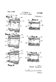
- FIG. 9 is an enlarged longitudinal sectional view of the outer end portion of the other of said insulating sleeves illustrating the novel curved surfaces employed in the present invention.
- FIG. 10 is an enlarged longitudinal sectional view of the outer end portion of a sleeve according to a modified form of the invention.
- FIG. 11 is a longitudinal section through the ends of a pair of cooperating sleeves one of which is constructed as shown in FIG. 10;
- FIG. 12 is an enlarged longitudinal sectional view of the outer end portion of a sleeve according to a further modified form of the invention.
- FIG. 13 is a longitudinal section through the outer end portion of a pair of sleeves one of which is constructed as shown in FIG. 12;
- FIG. 14 is an enlarged longitudinal sectional view of the outer end portion of a sleeve according to a still further modified form of the invention.
- FIG. 15 is a longitudinal section through a pair of sleeves one of which is constructed as illustrated in FIG. 14.
- FIG. 1 the overall connector assembly in operative locked position, the assembly serving to interconnect first and second insulated cables indicated by reference numerals 10 and 11 respectively.
- the outer ends of each of the cables are bared, the insulation of the two cables terminating at points 12 and 13 respectively, the outer ends of the insulation being seated against an annular shoulder formed in the surrounding insulating sleeves indicated generally by reference numerals 14 and 15 respectively.
- This coupling element indicated generally by reference numeral 21 includes a first substantially cylindrical portion 21 formed integral with an enlarged cylindrical portion 22, the rear end of the element comprising a hollow cylindrical portion 23 for a purpose hereinafter described.
- Formed integrally with the outer surface of portion 22 is a radially outwardly projecting pin 25, the function of which will be hereinafter set forth.
- a circumferentially extending groove 36 is formed throughout a major portion of the circumference of cylindrical portion 21 and is tudinally extending cutout portion 31.
- the coupling element is split longitudinally thereof as indicated at 33 to provide a certain degree of resilience to the outer end of the coupling element to ensure that it fits snugly within the cooperating coupling element.
- Coupling element 23 is formed of a suitable metallic electrically conductive material such as brass or the like to provid a good electrical interconnection between the cable ends.
- a hollow metallic sleeve 35 formed of a readily deformable material such as copper has the forward end thereof silver-brazed within the opening provided within portion 23 of the coupling element.
- This silver-brazing is indicated by reference numeral 36.
- Sleeve 35 is crimped to the bared end of cable 11) in a well-known manner, the depression formed in the sleeve and cable end by said crimping being indicated at 37.
- the coupling element 20 is securely mechanically and electrically interconnected with the outer end of cable 14
- the cooperating electrical coupling element is indicated generally by reference numeral 40 and includes a main hollow cylindrical portion 41 having a reduced hollow end portion 42 at one end thereof.
- a radially outwardly extending pin 43 is formed integral with the outer surface of cylindrical portion 41, the purpose of which will be hereinafter set forth.
- a radially inwardly extending pin 44 is formed on the inner surface of cylindrical portion 41, pinv 44 being adapted to lock the two elements together when coupling element 40 is slid over coupling element 20 such that pin 44 first rides longitudinally along the cutout portion 31 and thence into the slot 30 formed in coupling element 26 upon relative rotation of the coupling elements 20 and 40. It is believed apparent that relative longitudinal movement and the rotational movement between the two coupling elements serve to effectively lock them together, the unlocking action being merely a reversal of these movements.
- a hollow sleeve 45 similar to sleeve 35 is silver-brazed as indicated at 46 within the opening in cylindrical portion 42 of coupling element 40.
- Sleeve 45 is crimped as indicated at 47 to the outer end of cable 11 to thereby provide an effective mechanical and electrical interconnection with the cable.
- Each of sleeves 14 and 15 are formed of a suitable insulating material such as neoprene or the like, each of the sleeves having a longitudinal bore extending therethrough and further comprising inner reduced end portions 14' and 15 and outer enlarged portions 14" and 15" respectively.
- the bores of sleeves 14 and 15 are enlarged to provide annular recesses 50 and 51 respectively.
- annular rings 52 and in communication with a longi- 53 respectively are Embedded within these recesses, the rings being formed of a suitable metallic material such as brass or the like
- ring 52 is provided with diametrically opposite slots 54, these slots opening toward the outer end of the associated sleeve 14 and terminating at a point 55 as seen in FIG.
- a pair of diametrically opposite openings 57 are provided through ring 52 at approximately 90 degree intervals from slots 54, the material of the sleeve 14 extending within such openings to firmly lock the ring in place and bond it securely to the sleeve to prevent relative rotation therebetween.
- ring 53 is also provided with a pair of substantially diametrically opposite slots 60 which open toward the outer end of the associated sleeve 15 and terminate at a point 61 short of the rear surface 62 of the ring 53.
- Pin 43 of coupling element 40 is received within one of slots 60 in a manner similar to that in which the pin of the other coupling element is received within the slot in the associated ring for preventing relative rotation between the sleeve and its associated coupling element.
- a pair of diametrically opposite openings 65 are also provided through ring 53, the material of sleeve 15 extending within these openings to lock the ring 53 in operative position and firmly bond it to the associated sleeve.
- FIG. 1 The interlocking position of the components as illustrated in FIG. 1, and FIG. 8 of the drawing illustrates the manner in whichpin 44 of coupling element 40 rests within groove 30 formed in coupling element 20 to lock the elements in operative position.
- a lip means is formed on the inner surfaces of the outer end of sleeves 15 and comprises a pair of arcuate radially inwardly projecting portions formed integral with the sleeve and spaced from one another so as to provide diametrically opposite slots 72 and 73.
- arcuate portions and 71 have a relatively small longitudinal dimension and a pair of longitudinally extending grooves and 76 as seen most clearly in FIG. 8, for example, are formed in the inner surface of sleeve 15, grooves 75 and 76 being axially aligned with slots 72 and 73.
- the sleeves When it is desired to assemble the apparatus, the sleeves are initially slipped over the insulated cables and the coupling elements are secured to the hated ends of the cables. The sleeves are then moved toward the outer ends of the cables whereupon coupling element 20 will move into the operative position shown in FIG. 1 with pin 25 thereof within slot 54 in ring 52. As sleeve 15 moves outwardly with respect to the end of cable 11, pin 43 formed on the outer surface of coupling element 40 will pass through one of slots 72 or 73 and then along one of grooves 75 and 76 into one of the slots 60 formed in ring 53. As the coupling element 40 reaches its final operative position as shown in FIG. 1, the end wall 40' of coupling element 40 will snap in behind portions 70 and 71 of the lip means to lock the coupling element 40 in operative position.
- a water-tight seal is obtained at the inner or remote ends of the sleeves with respect to the cables by wrapping insulating tape indicated by reference numerals 70 and 71 about the ends of the sleeves and over a portion of the cable insulation.
- This tape is preferably of rubber or rubber-like substance and 53 is preferably vulcanized in place so as to form a watertight seal with both of the sleeves and the cable insulation immediately adjacent thereto.
- a feature of the invention is the means for providing a water-tight joint between the adjacent ends of the sleeves 14 and 15 which are interengageable with one another.
- the structure of a first modification can be most clearly understood by reference to FIG. 9 of the drawing which shows an enlarged view of the end portion of sleeve 15 with coupling element 40 in place therein.
- the outer surface of sleeve 15 connects with a radially inwardly extending annular shoulder 8-0 which in turn intersects a curved outer surface 81 at what may be termed the base portion of surface 81 indicated by reference numeral 82.
- Curved surface 81 extends outwardly to what may be termed a tip portion 83.
- Surface 81 is constructed in a novel manner in order to cooperate with a complementary shaped surface formed on the inner surface of the outer portion of sleeve 14 whereby the cooperating surfaces provide an eflective water-tight seal when in engagement and permit ready assembly and disassembly of the two sleeves.
- surface 81 is such that the surface defines a plurality of adjacent cross-sectional areas extending axially along the longitudinal axis AA of the sleeve, each of these cross-sectional areas being circular. As seen in FIG. 9, the diameter of the cross-sectional area at the base portion of surface 81 is greater than that at the tip portion of the surface. In addition, the diameters of the cross-sectional areas increase from the base portion toward an intermediate portion and then diminish from the intermediate portion to the tip portion.
- surface 31 Another way of stating the construction of surface 31 is that it consists of a number of arcs extending longitudinally of the axis AA of the sleeve. Two diametrically opposite arcs are visible in FIG. 9, the upper arc being formed about a center indicated by letter B and the lower arc being formed about a center indicated by letter C. It will be noted that the center of each individual arc of the surface 81 is at a point spaced on the far side of the longitudinal axis of the sleeve, and in addition, it will be noted that the centers of curvature of all the arcs included in the surface 81 will define a circle.
- the inner surface 85 formed within the outer end of sleeve 14 is formed in an identical manner with that of surface 81 so as to be perfectly complementary thereto.
- An outer annular shoulder 85 is formed at the tip end of the body means 15 and a similar annular shoulder 87 is formed in body means 14, these two shoulders engaging one another when in operative position as shown in FIG. 1.
- These surfaces 81 and 85 are so configured that they can easily snap into place and provide an effective fluid-tight seal, and yet can be readily removed from one another.
- sleeves 14 and 15 are formed of a resilient material such as neoprene, this material being very rugged and yet having sufiicient flexibility to permit a certain amount of distortion thereof in order to permit the desired locking action.
- FIGS. 10 and 11 a modified form of the invention is illustrated wherein parts similar to the components shown in FIGS. 1-9 have been given the same reference numerals preceded by a l or in other words parts 114 and parts 115 correspond to parts 14 and 15 as shown in FIGS. 1-9, etc.
- the outer end portion of insulating sleeve 115 is provided with a first frustoconical surface 121 which intersects a second frustoconical surface 122. It is apparent that surface 121 flares outwardly from the shoulder portion 123 of the insulating sleeve 115, and that surface 122 flares inwardly from its point of intersection with surface 121 to the terminal end of the insulating sleeve. This arrangement may be considered to define a double bevelled end portion.
- annular rings similar to annular rings 52 and 53 as shown in FIG. 1 are embedded in sleeves 114 and respectively, and have diametrically opposite slots as aforedescribed.
- a lip means is formed on the inner surface of the outer end of sleeve 115 and comprises a pair of arcuate radially inwardly projecting portions 170 and 171 which have the opposite ends spaced from one another so as to provide a pair of diametrically opposite slots one of which is seen in FIG. 10 and is identified by reference numeral 172. It will be understood that this structure is similar to that shown for example in FIG. 6 and serves the identical purpose.
- a pair of longitudinally extending grooves are provided in the inner surface of sleeve 115 in alignment with the slots defined by the lip means, one of these grooves 175 being illustrated in FIG. 10.
- sleeve 114 is provided with an inner surface or socket 125 which is complementary to and snugly receives the outer double bevelled end portion of sleeve 115 so as to provide a fluid-tight joint therewith.
- FIGS. 12 and 13 a further modified form of the invention is illustrated wherein components which have the identical construction as similar components in the modification shown in FIGS. 10 and 11 have been given the same reference numerals primed. It will be understood that the only structural distinction between this modification and that shown in FIGS. 10 and 11 is the configuration of the outer end portions of the sleeves 114 and 115'.
- the outer end portion of sleeve 115' includes a shoulder 128 from which extends a substantially cylindrical portion 129 of reduced diameter and having a peripheral rib 130 extending circumferentially therearound.
- the outer end portion of sleeve 114' is provided with a substantially cylindrical inner surface 131 which snugly receives the portion 129 of sleeve 115', and a circumferentially extending groove 132 is adapted to receive rib 130. This interengagement of the outer end portions of the two sleeves serves to provide a fluid-tight seal.
- FIGS. 14 and 15 a still further modified form of the invention is illustrated wherein components identical in construction to those shown in the modification illustrated in FIGS. 10 and 11 have been given the same reference numeral double primed, it being understood that again the only distinction between this modification and that shown in FIGS. 10 and 11 is the configuration of the outer end portions of the two sleeves.
- sleeve 115 includes a shoulder portion 135 from which extends an outwardly projecting inwardly tapering substantially frusto-conical surface 136.
- FIG. 14 shows a shoulder portion 135 from which extends an outwardly projecting inwardly tapering substantially frusto-conical surface 136.
- the outer end of sleeve 114' is provided with an inner surface or socket 137 which is complementary in configuration to surface 136 and is adapted to snugly receive the outer end portion of sleeve 115' so as to provide a fluid-tight seal therewith.
- sleeves 14 and 15 have been shown as sealed to the associated insulated cables by vulcanizing the dielectric material at the points between the sleeves and the cables.
- the openings in each of the sleeves which receive the insulated cables may be dimensioned such that they tightly fit about the insulation in the sleeves to provide an effective seal without the necessity of utilizing an additional sealing means.
- a cable connector assembly comprising a pair of insulated cable ends, a first electrically conductive coupling element electrically connected to one of said cable ends, a second electrically conductive coupling element electrically connected to the other of said cable ends, a first insulating sleeve disposed in surrounding relationship to said one cable end and sealingly engaged therewith, a second insulating sleeve disposed in surrounding relationship to the other of said cable ends and sealingly engaged therewith, said insulating sleeves having int'erengageable outer end portions which cooperate to form a fluid-tight joint in engagement with one another, said outer end portions having contactable surfaces of complementary configuration, said second coupling element having an outer end portion which is adapted to be received in the bore formed longitudinally through said second sleeve, said second sleeve having an inwardly projecting lip means formed at the outer end of the inner surface thereof, the outer end of said second coupling element engaging said lip means for retaining the second coupling element in operative position, said second sleeve being provided with
- each of said contactable surfaces of complementary configuration defines a plurality of longitudinally extending arcs, each of said arcs being formed about a center of curvature, the centers of curvature defining an annular path extending around the longitudinal axis of the associated sleeve.
- each of said contactable surfaces of complementary configuration defines a double beveled configuration.
- each of said contactable surfaces of complementary configuration is substantially cylindrical in configuration, one of said last-mentioned surfaces having a circumferential groove formed therein, and the other of said last-mentioned surfaces having a circumferentially extending rib projecting therefrom for fitting snugly within said circumferentially extending groove.
- each of said contactable surfaces of complementary configuration is substantially frusto-conical in configuration.
Description
Aug. 4, 1964 R. SENIOR, JR
CABLE CONNECTOR ASSEMBLY 2 Sheets-Sheet 1 Filed Sept. 24, 1962 INVENTOR. Robert Senior, Jr. m
flrry;
N w W 3E m mv w @1 6 vi wk 8 mm mm Ta VL U V g- 1964 R. SENIOR, JR 3,143,384
CABLE CONNECTOR ASSEMBLY Filed Sept. 24, 1962 JMO H4 F G. 1
z/Mme W ATTORNEYS United States Patent 3,143,334 CABLE CONNECT-GR ASSEMBLY Robert Senior, in, Cincinnati, Ohio, assignmto Empire Products, Incorporated, Cincinnati, Ohio, a corporation of Ohio Filed Sept. 24, 1962, Ser. No. 227,628 Claims. (Cl. 339-59) The present application is a continuation-in-part of copending US. patent application Ser. No. 831,292 filed August 3, 1959, now abandoned.
The present invention relates to a new and novel cable connector assembly and more particularly to a cable connector assembly which is especially adapted to be mounted in the field and which provides a quickly and easily connectable and disconnectable means for providing a fluidtight joint between the ends of the cables.
The present invention particularly relates to a connector assembly which is adapted for use with heavy-duty welding cables and the like wherein it is necessary to provide an especially rugged structure, and one which provides a good electrical connection between a pair of cable ends and at the same time will provide an effective fluid-tight seal thereat to prevent corrosion of the electrical connector elements and to obviate the possibility of electrical shocks occu ring through any leakage which might occur from the assembly.
Heretofore, it has been a common practice to mold some sort of insulating means about the cable ends in the factory whereby the cables are of fixed length and cannot be cut and reconnected in the field in accordance with any particular job. The present invention provides an arrangement whereby the cables may be cut to any desired length and the coupling structure mounted upon the cable ends in the field.
In addition, the connector assembly of the present invention provides a special construction whereby the cable ends may be easily snapped into fluid-tight engagement in a simple manner and wherein they can subsequently be quickly disconnected with a minimum of effort while retaining a very effective fluid seal and electrical connection between the cable ends while in operative position.
The novel arrangement of the present invention includes a pair of electrical connector elements which are secured to the bared cable ends and are of the type which are rotated relative to one another to effect locking engagement thereof. Disposed in surrounding relationship to the cable ends and the electrical connectors are a pair of interengageable coupling insulating sleeves.
The insulating sleeves are sealed to the insulated portions of the cables, and the sleeves and associated coupling elements are provided with inter-engageable means for preventing relative rotation therebetween.
A feature of the present invention is the manner of construction of the outer ends of the insulating sleeves. These outer ends are provided with cooperating surfaces which engage one another in a manner such that when in engagement a fluid-tight seal is provided. The outer end portions of the insulating sleeves may be constructed in a number of different manners, and several specific modified configurations are shown herein, it being understood that the outer end portions of the sleeves may be varied from the specific configurations illustrated. In a first important form of the invention, the surfaces are provided with a special curved complementary configuration which permits the sleeves to be snapped into and out of engagement with one another in a simple manner and yet which provides a very effective fluid-tight joint. In the modified forms of the invention, the outer end portions of the sleeves are of complementary configuration so that they also serve to provide a fluid-tight seal. In this manner, a most simple and effective means is provided for interconnecting adjacent outer end portions of the two insulating sleeves.
In each of the various modifications of the invention, lip means is provided at the outer end of one of the cooperating sleeves for assisting in retaining the associated electrical connector in place. Longitudinally extending groove means is provided in the inner surface of this sleeve for facilitating insertion of the associated electrical coupling element which has an outwardly projecting member thereon adapted to be received within a notch formed in a ring member embedded in the associated sleeve.
An object of the present invention is to provide a new and novel cable connector assembly which can effectively be mounted upon cable ends in the field.
Another object of the invention is the provision of a cable connector assembly which provides a good electrical connection and furthermore, which provides a fluid-tight seal between the cable ends when in operative position.
Yet another object of the invention is to provide a pair of insulating sleeves provided with interengageable outer end portions which can be quickly and easily assembled to and disassembled from one another.
A still further object of the invention is to provide a cable connector assembly which is quite simple and inexpensive in construction, and yet which is quite sturdy and reliable in operation.
Other objects and many attendant advantages of the invention will become more apparent when considered in connection with the specification and accompanying drawing, wherein:
FIG. 1 is a longitudinal section of a cable connector assembly according to the present invention;
FIG. 2 is a perspective view of one of the electrical coupling elements of the invention;
FIG. 3 is a perspective view of an end portion of one of the insulating sleeves;
FIG. 4 is a sectional view taken along line 44 of FIG. 1, looking in the direction of the arrows;
FIG. 5 is a perspective view of the other of the electrical coupling elements of the present invention;
FIG. 6 is a perspective view of an end portion of the other of the insulating sleeves;
FIG. 7 is a cross-sectional view taken along line 77 of FIG. 1 looking in the direction of the arrows;
FIG. 8 is a cross-sectional View taken along line 88 of FIG. 1 looking in the direction of the arrows;
FIG. 9 is an enlarged longitudinal sectional view of the outer end portion of the other of said insulating sleeves illustrating the novel curved surfaces employed in the present invention;
FIG. 10 is an enlarged longitudinal sectional view of the outer end portion of a sleeve according to a modified form of the invention;
FIG. 11 is a longitudinal section through the ends of a pair of cooperating sleeves one of which is constructed as shown in FIG. 10;
FIG. 12 is an enlarged longitudinal sectional view of the outer end portion of a sleeve according to a further modified form of the invention;
FIG. 13 is a longitudinal section through the outer end portion of a pair of sleeves one of which is constructed as shown in FIG. 12;
FIG. 14 is an enlarged longitudinal sectional view of the outer end portion of a sleeve according to a still further modified form of the invention; and
FIG. 15 is a longitudinal section through a pair of sleeves one of which is constructed as illustrated in FIG. 14.
Referring now to the drawing wherein like reference characters designate corresponding parts throughout the several views, there is shown in FIG. 1, the overall connector assembly in operative locked position, the assembly serving to interconnect first and second insulated cables indicated by reference numerals 10 and 11 respectively. The outer ends of each of the cables are bared, the insulation of the two cables terminating at points 12 and 13 respectively, the outer ends of the insulation being seated against an annular shoulder formed in the surrounding insulating sleeves indicated generally by reference numerals 14 and 15 respectively.
Referring now to FIG. 2 of the drawing, the electrical coupling element associated with the outer end of the cable 11 is illustrated. This coupling element indicated generally by reference numeral 21 includes a first substantially cylindrical portion 21 formed integral with an enlarged cylindrical portion 22, the rear end of the element comprising a hollow cylindrical portion 23 for a purpose hereinafter described. Formed integrally with the outer surface of portion 22 is a radially outwardly projecting pin 25, the function of which will be hereinafter set forth.
A circumferentially extending groove 36, is formed throughout a major portion of the circumference of cylindrical portion 21 and is tudinally extending cutout portion 31. The coupling element is split longitudinally thereof as indicated at 33 to provide a certain degree of resilience to the outer end of the coupling element to ensure that it fits snugly within the cooperating coupling element. Coupling element 23 is formed of a suitable metallic electrically conductive material such as brass or the like to provid a good electrical interconnection between the cable ends.
Referring again to FIG. 1, a hollow metallic sleeve 35 formed of a readily deformable material such as copper has the forward end thereof silver-brazed within the opening provided within portion 23 of the coupling element. This silver-brazing is indicated by reference numeral 36. Sleeve 35 is crimped to the bared end of cable 11) in a well-known manner, the depression formed in the sleeve and cable end by said crimping being indicated at 37. In this manner, the coupling element 20 is securely mechanically and electrically interconnected with the outer end of cable 14 Referring now to FIG. of the drawing, the cooperating electrical coupling element is indicated generally by reference numeral 40 and includes a main hollow cylindrical portion 41 having a reduced hollow end portion 42 at one end thereof. A radially outwardly extending pin 43 is formed integral with the outer surface of cylindrical portion 41, the purpose of which will be hereinafter set forth. A radially inwardly extending pin 44 is formed on the inner surface of cylindrical portion 41, pinv 44 being adapted to lock the two elements together when coupling element 40 is slid over coupling element 20 such that pin 44 first rides longitudinally along the cutout portion 31 and thence into the slot 30 formed in coupling element 26 upon relative rotation of the coupling elements 20 and 40. It is believed apparent that relative longitudinal movement and the rotational movement between the two coupling elements serve to effectively lock them together, the unlocking action being merely a reversal of these movements.
Referring again to FIG. 1, a hollow sleeve 45 similar to sleeve 35 is silver-brazed as indicated at 46 within the opening in cylindrical portion 42 of coupling element 40. Sleeve 45 is crimped as indicated at 47 to the outer end of cable 11 to thereby provide an effective mechanical and electrical interconnection with the cable.
Each of sleeves 14 and 15 are formed of a suitable insulating material such as neoprene or the like, each of the sleeves having a longitudinal bore extending therethrough and further comprising inner reduced end portions 14' and 15 and outer enlarged portions 14" and 15" respectively. The bores of sleeves 14 and 15 are enlarged to provide annular recesses 50 and 51 respectively. Embedded within these recesses are annular rings 52 and in communication with a longi- 53 respectively, the rings being formed of a suitable metallic material such as brass or the like As seen most clearly in FIG. 4 of the drawings, ring 52 is provided with diametrically opposite slots 54, these slots opening toward the outer end of the associated sleeve 14 and terminating at a point 55 as seen in FIG. 1 short of the rear surface 56 of ring 52. A pair of diametrically opposite openings 57 are provided through ring 52 at approximately 90 degree intervals from slots 54, the material of the sleeve 14 extending within such openings to firmly lock the ring in place and bond it securely to the sleeve to prevent relative rotation therebetween.
One of the slots 54 in the ring 52 is also clearly visible in FIG. 3 of the drawing, it being apparent that when the coupling element 20 is moved into sleeve 14, pin 25 is adapted to be received within slot 54 such that when in operative position as seen in FIG. 1, the cooperation between pin 25 and ring 52 prevents relative rotation between the sleeve 14 and the coupling element and cable. This ensures that the coupling elements can be rotated into locking position merely by turning the surrounding sleeves.
As seen most clearly in FIG. 7, ring 53 is also provided with a pair of substantially diametrically opposite slots 60 which open toward the outer end of the associated sleeve 15 and terminate at a point 61 short of the rear surface 62 of the ring 53. Pin 43 of coupling element 40 is received within one of slots 60 in a manner similar to that in which the pin of the other coupling element is received within the slot in the associated ring for preventing relative rotation between the sleeve and its associated coupling element. A pair of diametrically opposite openings 65 are also provided through ring 53, the material of sleeve 15 extending within these openings to lock the ring 53 in operative position and firmly bond it to the associated sleeve.
The interlocking position of the components as illustrated in FIG. 1, and FIG. 8 of the drawing illustrates the manner in whichpin 44 of coupling element 40 rests within groove 30 formed in coupling element 20 to lock the elements in operative position.
Referring now to FIG. 6, a lip means is formed on the inner surfaces of the outer end of sleeves 15 and comprises a pair of arcuate radially inwardly projecting portions formed integral with the sleeve and spaced from one another so as to provide diametrically opposite slots 72 and 73. It will be noted that arcuate portions and 71 have a relatively small longitudinal dimension and a pair of longitudinally extending grooves and 76 as seen most clearly in FIG. 8, for example, are formed in the inner surface of sleeve 15, grooves 75 and 76 being axially aligned with slots 72 and 73.
When it is desired to assemble the apparatus, the sleeves are initially slipped over the insulated cables and the coupling elements are secured to the hated ends of the cables. The sleeves are then moved toward the outer ends of the cables whereupon coupling element 20 will move into the operative position shown in FIG. 1 with pin 25 thereof within slot 54 in ring 52. As sleeve 15 moves outwardly with respect to the end of cable 11, pin 43 formed on the outer surface of coupling element 40 will pass through one of slots 72 or 73 and then along one of grooves 75 and 76 into one of the slots 60 formed in ring 53. As the coupling element 40 reaches its final operative position as shown in FIG. 1, the end wall 40' of coupling element 40 will snap in behind portions 70 and 71 of the lip means to lock the coupling element 40 in operative position.
After the sleeves 14 and 15 have been moved into operative position as shown, a water-tight seal is obtained at the inner or remote ends of the sleeves with respect to the cables by wrapping insulating tape indicated by reference numerals 70 and 71 about the ends of the sleeves and over a portion of the cable insulation. This tape is preferably of rubber or rubber-like substance and 53 is preferably vulcanized in place so as to form a watertight seal with both of the sleeves and the cable insulation immediately adjacent thereto.
As discussed previously, a feature of the invention is the means for providing a water-tight joint between the adjacent ends of the sleeves 14 and 15 which are interengageable with one another. The structure of a first modification can be most clearly understood by reference to FIG. 9 of the drawing which shows an enlarged view of the end portion of sleeve 15 with coupling element 40 in place therein. The outer surface of sleeve 15 connects with a radially inwardly extending annular shoulder 8-0 which in turn intersects a curved outer surface 81 at what may be termed the base portion of surface 81 indicated by reference numeral 82. Curved surface 81 extends outwardly to what may be termed a tip portion 83. Surface 81 is constructed in a novel manner in order to cooperate with a complementary shaped surface formed on the inner surface of the outer portion of sleeve 14 whereby the cooperating surfaces provide an eflective water-tight seal when in engagement and permit ready assembly and disassembly of the two sleeves.
The construction of surface 81 is such that the surface defines a plurality of adjacent cross-sectional areas extending axially along the longitudinal axis AA of the sleeve, each of these cross-sectional areas being circular. As seen in FIG. 9, the diameter of the cross-sectional area at the base portion of surface 81 is greater than that at the tip portion of the surface. In addition, the diameters of the cross-sectional areas increase from the base portion toward an intermediate portion and then diminish from the intermediate portion to the tip portion.
Another way of stating the construction of surface 31 is that it consists of a number of arcs extending longitudinally of the axis AA of the sleeve. Two diametrically opposite arcs are visible in FIG. 9, the upper arc being formed about a center indicated by letter B and the lower arc being formed about a center indicated by letter C. It will be noted that the center of each individual arc of the surface 81 is at a point spaced on the far side of the longitudinal axis of the sleeve, and in addition, it will be noted that the centers of curvature of all the arcs included in the surface 81 will define a circle. It should be fully understood that the inner surface 85 formed within the outer end of sleeve 14 is formed in an identical manner with that of surface 81 so as to be perfectly complementary thereto. An outer annular shoulder 85 is formed at the tip end of the body means 15 and a similar annular shoulder 87 is formed in body means 14, these two shoulders engaging one another when in operative position as shown in FIG. 1. These surfaces 81 and 85 are so configured that they can easily snap into place and provide an effective fluid-tight seal, and yet can be readily removed from one another. The ability of the two sleeves 14 and 15 to be assembled and disassembled in the aforementioned manner is additionally due to the fact that sleeves 14 and 15 are formed of a resilient material such as neoprene, this material being very rugged and yet having sufiicient flexibility to permit a certain amount of distortion thereof in order to permit the desired locking action.
Referring now to FIGS. 10 and 11, a modified form of the invention is illustrated wherein parts similar to the components shown in FIGS. 1-9 have been given the same reference numerals preceded by a l or in other words parts 114 and parts 115 correspond to parts 14 and 15 as shown in FIGS. 1-9, etc.
It will be understood that the surrounding insulating sleeves 114 and 115 as well as the electrical coupling elements 129 and 146 are identical with their corresponding components as seen in FIG. 1, for example, with the exception that the outer end portions of the sleeves are provided with different configurations.
As seen especially in FIG. 10, the outer end portion of insulating sleeve 115 is provided with a first frustoconical surface 121 which intersects a second frustoconical surface 122. It is apparent that surface 121 flares outwardly from the shoulder portion 123 of the insulating sleeve 115, and that surface 122 flares inwardly from its point of intersection with surface 121 to the terminal end of the insulating sleeve. This arrangement may be considered to define a double bevelled end portion.
It will be understood that annular rings similar to annular rings 52 and 53 as shown in FIG. 1 are embedded in sleeves 114 and respectively, and have diametrically opposite slots as aforedescribed. A lip means is formed on the inner surface of the outer end of sleeve 115 and comprises a pair of arcuate radially inwardly projecting portions 170 and 171 which have the opposite ends spaced from one another so as to provide a pair of diametrically opposite slots one of which is seen in FIG. 10 and is identified by reference numeral 172. It will be understood that this structure is similar to that shown for example in FIG. 6 and serves the identical purpose. A pair of longitudinally extending grooves are provided in the inner surface of sleeve 115 in alignment with the slots defined by the lip means, one of these grooves 175 being illustrated in FIG. 10.
Referring to FIG. 11, it will be noted that the terminal end of sleeve 114 is provided with an inner surface or socket 125 which is complementary to and snugly receives the outer double bevelled end portion of sleeve 115 so as to provide a fluid-tight joint therewith.
Referring now to FIGS. 12 and 13, a further modified form of the invention is illustrated wherein components which have the identical construction as similar components in the modification shown in FIGS. 10 and 11 have been given the same reference numerals primed. It will be understood that the only structural distinction between this modification and that shown in FIGS. 10 and 11 is the configuration of the outer end portions of the sleeves 114 and 115'.
Referring particularly to FIG. 12, it will be seen that the outer end portion of sleeve 115' includes a shoulder 128 from which extends a substantially cylindrical portion 129 of reduced diameter and having a peripheral rib 130 extending circumferentially therearound.
As seen in FIG. 13, the outer end portion of sleeve 114' is provided with a substantially cylindrical inner surface 131 which snugly receives the portion 129 of sleeve 115', and a circumferentially extending groove 132 is adapted to receive rib 130. This interengagement of the outer end portions of the two sleeves serves to provide a fluid-tight seal.
Referring now to FIGS. 14 and 15, a still further modified form of the invention is illustrated wherein components identical in construction to those shown in the modification illustrated in FIGS. 10 and 11 have been given the same reference numeral double primed, it being understood that again the only distinction between this modification and that shown in FIGS. 10 and 11 is the configuration of the outer end portions of the two sleeves. As seen particularly in FIG. 14, sleeve 115 includes a shoulder portion 135 from which extends an outwardly projecting inwardly tapering substantially frusto-conical surface 136. As seen in FIG. 15, the outer end of sleeve 114' is provided with an inner surface or socket 137 which is complementary in configuration to surface 136 and is adapted to snugly receive the outer end portion of sleeve 115' so as to provide a fluid-tight seal therewith.
In each of the modifications shown in FIGS. 10-15, it will be understood that in assembling the electrical coupling elements 140, 140' and 140" within the associated surrounding insulating sleeves 115, 115' and 115" the radially outwardly projecting pin formed on the outer surface of the coupling element will pass through one of the slots 172, 172' or 172" and then along one of the grooves 175, 175 and 175" and into the slot of a ring embedded within the sleeve, the end wall of the coupling elements in each case snapping in behind the lip portions of the associated sleeve.
It is apparent from the foregoing that there is provided a new and novel cable connector assembly which is adapted 'to be readily mounted upon cables in the field, thereby permitting the cables to be cut to any desired length. The assembly provides a very effective electrical and mechanical interconnection between the cable ends and at the same time provides a good fluid-tight seal therebetween. A pair of insulating sleeves are provided and have novel outer end portions which can be quickly and easily assembled and disassembled, with respect to one another. The structure of the present invention is quite simple and inexpensive in construction and yet is quite sturdy and reliable in operation.
As this invention may be embodied in several forms without departing from the spirit or essential character istics thereof, the present embodiments are therefore illustrative and not restrictive, and since the scope of the invention is defined by the appended claims, all changes that fall within the metes and bounds of the claims or that form their functional as Well as conjointly cooperative equivalents are therefore intended to be embraced by those claims.
While sleeves 14 and 15 have been shown as sealed to the associated insulated cables by vulcanizing the dielectric material at the points between the sleeves and the cables. the openings in each of the sleeves which receive the insulated cables may be dimensioned such that they tightly fit about the insulation in the sleeves to provide an effective seal without the necessity of utilizing an additional sealing means.
I claim:
1. A cable connector assembly comprising a pair of insulated cable ends, a first electrically conductive coupling element electrically connected to one of said cable ends, a second electrically conductive coupling element electrically connected to the other of said cable ends, a first insulating sleeve disposed in surrounding relationship to said one cable end and sealingly engaged therewith, a second insulating sleeve disposed in surrounding relationship to the other of said cable ends and sealingly engaged therewith, said insulating sleeves having int'erengageable outer end portions which cooperate to form a fluid-tight joint in engagement with one another, said outer end portions having contactable surfaces of complementary configuration, said second coupling element having an outer end portion which is adapted to be received in the bore formed longitudinally through said second sleeve, said second sleeve having an inwardly projecting lip means formed at the outer end of the inner surface thereof, the outer end of said second coupling element engaging said lip means for retaining the second coupling element in operative position, said second sleeve being provided with a longitudinally extending groove formed in the inner surface thereof for receiving outwardly projecting pin means formed on said second coupling element, and a ring member mounted in fixed position within said second sleeve and having a notch formed therein, said notch opening toward the outer end of said sleeve and being in alignment with the groove formed in said second sleeve, said second coupling element including outwardly projecting pin means adapted to slide along said groove and into the aligned notch in said ring member to prevent relative rotation between said second coupling element and said second sleeve.
2. Apparatus as defined in claim 1 wherein each of said contactable surfaces of complementary configuration defines a plurality of longitudinally extending arcs, each of said arcs being formed about a center of curvature, the centers of curvature defining an annular path extending around the longitudinal axis of the associated sleeve.
3. Apparatus as defined in claim 1 wherein each of said contactable surfaces of complementary configuration defines a double beveled configuration.
4. Apparatus as defined in claim 1 wherein each of said contactable surfaces of complementary configuration is substantially cylindrical in configuration, one of said last-mentioned surfaces having a circumferential groove formed therein, and the other of said last-mentioned surfaces having a circumferentially extending rib projecting therefrom for fitting snugly within said circumferentially extending groove.
5. Apparatus as defined in claim 1 wherein each of said contactable surfaces of complementary configuration is substantially frusto-conical in configuration.
References Cited in the file of this patent UNITED STATES PATENTS 971,363 Doyle Sept. 27, 1910 1,742,312 Hagel Jan. 7, 1930 2,015,590 Cavanagh et a1 Sept. 24, 1935 2,389,455 Benander Nov. 20, 1945 2,448,509 Antony et a1 Sept. 7, 1948 2,742,622 Stevens Apr. 17, 1956 2,782,391 Kirk Feb. 19, 1957 2,907,973 Stevens Oct. 6, 1959 FOREIGN PATENTS 490,013 Great Britain Aug. 5, 1938
Claims (1)
1. A CABLE CONNECTOR ASSEMBLY COMPRISING A PAIR OF INSULATED CABLE ENDS, A FIRST ELECTRICALLY CONDUCTIVE COUPLING ELEMENT ELECTRICALLY CONNECTED TO ONE OF SAID CABLE ENDS, A SECOND ELECTRICALLY CONDUCTIVE COUPLING ELEMENT ELECTRICALLY CONNECTED TO THE OTHER OF SAID CABLE ENDS A FIRST INSULATING SLEEVE DISPOSED IN SURROUNDING RELATIONSHIP TO SAID ONE CABLE END AND SEALINGLY ENGAGED THEREWITH, A SECOND INSULATING SLEEVE DISPOSED IN SURROUNDING RELATIONSHIP TO THE OTHER OF SAID CABLE ENDS AND SEALINGLY ENGAGED THEREWITH, SAID INSULATING SLEEVES HAVING INTERENGAGEABLE OUTER END PORTIONS WHICH COOPERATE TO FORM A FLUID-TIGHT JOINT IN ENGAGEMENT WITH ONE ANOTHER, SAID OUTER END PORTIONS HAVING CONTACTABLE SURFACES OF COMPLEMENTARY CONFIGURATION, SAID SECOND COUPLING ELEMENT HAVING AN OUTER END PORTION WHICH IS ADAPTED TO BE RECEIVED IN THE BORE FORMED LONGITUDINALLY THROUGH SAID SECOND SLEEVE, SAID SECOND SLEEVE HAVING AN INWARDLY PROJECTING LIP MEANS FORMED AT THE OUTER END OF THE INNER SURFACE THEREOF, THE OUTER END OF SAID SECOND COUPLING ELEMENT ENGAGING SAID LIP MEANS FOR RETAINING THE SECOND COUPLING ELEMENT IN OPERATIVE POSITION, SAID SECOND SLEEVE BEING PROVIDED WITH A LONGITUDINALLY EXTENDING GROOVE FORMED IN THE INNER SURFACE THEREOF FOR RECEIVING OUTWARDLY PROJECTING PIN MEANS FORMED ON SAID SECOND COUPLING ELEMENT, AND A RING MEMBER MOUNTED IN FIXED POSITION WITHIN SAID SECOND SLEEVE AND HAVING A NOTCH FORMED THEREIN, SAID NOTCH OPENING TOWARD THE OUTER END OF SAID SLEEVE AND BEING IN ALIGNMENT WITH THE GROOVE FORMED IN SAID SECOND SLEEVE, SAID SECOND COUPLING ELEMENT INCLUDING OUTWARDLY PROJECTING PIN MEANS ADAPTED TO SLIDE ALONG SAID GROOVE AND INTO THE ALIGNED NOTCH IN SAID RING MEMBER TO PREVENT RELATIVE ROTATION BETWEEN SAID SECOND COUPLING ELEMENT AND SAID SECOND SLEEVE.
Priority Applications (1)
| Application Number | Priority Date | Filing Date | Title |
|---|---|---|---|
| US227628A US3143384A (en) | 1962-09-24 | 1962-09-24 | Cable connector assembly |
Applications Claiming Priority (1)
| Application Number | Priority Date | Filing Date | Title |
|---|---|---|---|
| US227628A US3143384A (en) | 1962-09-24 | 1962-09-24 | Cable connector assembly |
Publications (1)
| Publication Number | Publication Date |
|---|---|
| US3143384A true US3143384A (en) | 1964-08-04 |
Family
ID=22853837
Family Applications (1)
| Application Number | Title | Priority Date | Filing Date |
|---|---|---|---|
| US227628A Expired - Lifetime US3143384A (en) | 1962-09-24 | 1962-09-24 | Cable connector assembly |
Country Status (1)
| Country | Link |
|---|---|
| US (1) | US3143384A (en) |
Cited By (38)
| Publication number | Priority date | Publication date | Assignee | Title |
|---|---|---|---|---|
| US3226667A (en) * | 1965-03-04 | 1965-12-28 | Empire Prod Inc | Electrical connector assembly |
| US3396360A (en) * | 1966-08-26 | 1968-08-06 | Piaget Robert Edward | Coupling for cables or the like |
| US3456872A (en) * | 1967-12-19 | 1969-07-22 | Theodor H Troller | Pitch adjustable axial flow blower |
| US3519977A (en) * | 1968-01-11 | 1970-07-07 | Whitaker Cable Corp | High amperage quick disconnect electric coupling structure |
| US3757789A (en) * | 1971-10-26 | 1973-09-11 | I Shanker | Electromedical stimulator lead connector |
| US3829820A (en) * | 1972-07-13 | 1974-08-13 | Bunker Ramo | Plug and socket connector |
| US4173349A (en) * | 1978-08-24 | 1979-11-06 | General Motors Corporation | Connector interface sealing arrangement |
| FR2547121A1 (en) * | 1983-05-30 | 1984-12-07 | Pirelli Treficable | JUNCTION DEVICE FOR AERO-SUBTERRANEAN CONNECTION OF LOW VOLTAGE ELECTRIC CABLES |
| US4695110A (en) * | 1985-10-21 | 1987-09-22 | Amp Incorporated | Electrical connector apparatus |
| US4904198A (en) * | 1987-09-28 | 1990-02-27 | Rowe Industries, Inc. | Vibration-proof plug and socket |
| US5017161A (en) * | 1988-06-21 | 1991-05-21 | Legrand | Electric terminal connector |
| US5316502A (en) * | 1992-04-10 | 1994-05-31 | Union Connector Co., Inc. | Electrical connector with circuit protection |
| US5366392A (en) * | 1993-01-21 | 1994-11-22 | Bernard Welding Company | Quick connect electrical cable connector |
| FR2840458A1 (en) * | 2002-05-29 | 2003-12-05 | Richard Jean Capai | Single pole potential terminal for a cable used for cathodic protection of pipelines includes protective insulating element cooperating with cable coating and providing access to a contact element via an orifice |
| US20060199411A1 (en) * | 2005-03-07 | 2006-09-07 | Brian Singh | Windmill cable system and method |
| US20060237028A1 (en) * | 2005-04-21 | 2006-10-26 | Hamidy Nasser W | Dental floss |
| US7488224B1 (en) * | 2007-12-13 | 2009-02-10 | Cooper Technologies Company | Single pole cable connector |
| US20090156057A1 (en) * | 2007-12-13 | 2009-06-18 | Cooper Technologies Company | Single pole cable connector |
| US20110014809A1 (en) * | 2009-07-15 | 2011-01-20 | Michael John Spicer | Connector with keying member |
| US7892047B2 (en) | 2008-04-30 | 2011-02-22 | Cooper Technologies Company | Single pole cable connector with tamper resistant locking mechanism |
| US20110228458A1 (en) * | 2010-03-17 | 2011-09-22 | Otter Products, Llc | Multi-material protective case for sliding/articulating/rotating handheld electronic devices |
| US20110244714A1 (en) * | 2008-12-12 | 2011-10-06 | Tyco Electronics Amp Gmbh | High-current plug-in connector |
| US20110287654A1 (en) * | 2009-02-06 | 2011-11-24 | Fronius International Gmbh | Power jack for a welding device |
| US8608502B2 (en) * | 2012-05-08 | 2013-12-17 | Otter Products, Llc | Connection mechanism |
| US9241551B2 (en) | 2012-06-13 | 2016-01-26 | Otter Products, Llc | Protective case with compartment |
| US9300078B2 (en) | 2013-08-23 | 2016-03-29 | Otter Products, Llc | Waterproof housing for mobile electronic device and waterproof adapter for accessory device |
| US9398365B2 (en) | 2013-03-22 | 2016-07-19 | Otter Products, Llc | Earphone assembly |
| US9577697B2 (en) | 2015-05-27 | 2017-02-21 | Otter Products, Llc | Protective case with stylus access feature |
| US9615476B2 (en) | 2011-06-13 | 2017-04-04 | Treefrog Developments, Inc. | Housing for encasing a mobile device |
| US9955762B2 (en) | 2010-10-12 | 2018-05-01 | Treefrog Developments, Inc. | Housing for encasing an electronic device |
| US9960521B2 (en) | 2016-02-24 | 2018-05-01 | Otter Products, Llc | Connector for fluidly sealing an aperture of a protective case |
| US10005611B2 (en) | 2012-06-01 | 2018-06-26 | Treefrog Developments, Inc. | Protective case for electronic device |
| US10159320B2 (en) | 2016-09-07 | 2018-12-25 | Otter Products, Llc | Protective enclosure for encasing an electronic device |
| US10396843B2 (en) | 2011-06-13 | 2019-08-27 | Treefrog Developments, Inc. | Protective encasement for a mobile computing device |
| US10548380B2 (en) | 2013-02-01 | 2020-02-04 | Treefrog Developments, Inc. | Waterproof housing for an electronic device |
| US10827809B2 (en) | 2018-04-05 | 2020-11-10 | Otter Products, Llc | Protective case for electronic device |
| US10966496B2 (en) | 2009-08-21 | 2021-04-06 | Otter Products, Llc | Protective cushion cover for an electronic device |
| US10998658B2 (en) * | 2017-07-12 | 2021-05-04 | Autonetworks Technologies, Ltd. | Male terminal fitting and female terminal fitting |
Citations (9)
| Publication number | Priority date | Publication date | Assignee | Title |
|---|---|---|---|---|
| US971363A (en) * | 1910-01-06 | 1910-09-27 | Joseph Vincent Doyle | Connection for electric cars. |
| US1742312A (en) * | 1927-01-20 | 1930-01-07 | Eugene A Hagel | Electric-circuit-connecter plug |
| US2015590A (en) * | 1930-04-23 | 1935-09-24 | Ohio Rubber Co | Terminal |
| GB490013A (en) * | 1937-02-05 | 1938-08-05 | Hermetic Rubber Company Ltd | Improvements relating to electric couplings |
| US2389455A (en) * | 1944-06-22 | 1945-11-20 | Monowatt Electric Corp | Electrical connector |
| US2448509A (en) * | 1943-05-14 | 1948-09-07 | Sperry Corp | Electrical connector |
| US2742622A (en) * | 1953-04-02 | 1956-04-17 | Whitney Blake Co | Cable connector |
| US2782391A (en) * | 1952-10-02 | 1957-02-19 | Gen Motors Corp | Waterproof line connector |
| US2907973A (en) * | 1955-11-07 | 1959-10-06 | Empire Prod Inc | Cable connector assembly |
-
1962
- 1962-09-24 US US227628A patent/US3143384A/en not_active Expired - Lifetime
Patent Citations (9)
| Publication number | Priority date | Publication date | Assignee | Title |
|---|---|---|---|---|
| US971363A (en) * | 1910-01-06 | 1910-09-27 | Joseph Vincent Doyle | Connection for electric cars. |
| US1742312A (en) * | 1927-01-20 | 1930-01-07 | Eugene A Hagel | Electric-circuit-connecter plug |
| US2015590A (en) * | 1930-04-23 | 1935-09-24 | Ohio Rubber Co | Terminal |
| GB490013A (en) * | 1937-02-05 | 1938-08-05 | Hermetic Rubber Company Ltd | Improvements relating to electric couplings |
| US2448509A (en) * | 1943-05-14 | 1948-09-07 | Sperry Corp | Electrical connector |
| US2389455A (en) * | 1944-06-22 | 1945-11-20 | Monowatt Electric Corp | Electrical connector |
| US2782391A (en) * | 1952-10-02 | 1957-02-19 | Gen Motors Corp | Waterproof line connector |
| US2742622A (en) * | 1953-04-02 | 1956-04-17 | Whitney Blake Co | Cable connector |
| US2907973A (en) * | 1955-11-07 | 1959-10-06 | Empire Prod Inc | Cable connector assembly |
Cited By (56)
| Publication number | Priority date | Publication date | Assignee | Title |
|---|---|---|---|---|
| US3226667A (en) * | 1965-03-04 | 1965-12-28 | Empire Prod Inc | Electrical connector assembly |
| US3396360A (en) * | 1966-08-26 | 1968-08-06 | Piaget Robert Edward | Coupling for cables or the like |
| US3456872A (en) * | 1967-12-19 | 1969-07-22 | Theodor H Troller | Pitch adjustable axial flow blower |
| US3519977A (en) * | 1968-01-11 | 1970-07-07 | Whitaker Cable Corp | High amperage quick disconnect electric coupling structure |
| US3757789A (en) * | 1971-10-26 | 1973-09-11 | I Shanker | Electromedical stimulator lead connector |
| US3829820A (en) * | 1972-07-13 | 1974-08-13 | Bunker Ramo | Plug and socket connector |
| US4173349A (en) * | 1978-08-24 | 1979-11-06 | General Motors Corporation | Connector interface sealing arrangement |
| FR2547121A1 (en) * | 1983-05-30 | 1984-12-07 | Pirelli Treficable | JUNCTION DEVICE FOR AERO-SUBTERRANEAN CONNECTION OF LOW VOLTAGE ELECTRIC CABLES |
| US4695110A (en) * | 1985-10-21 | 1987-09-22 | Amp Incorporated | Electrical connector apparatus |
| US4904198A (en) * | 1987-09-28 | 1990-02-27 | Rowe Industries, Inc. | Vibration-proof plug and socket |
| US5017161A (en) * | 1988-06-21 | 1991-05-21 | Legrand | Electric terminal connector |
| US5316502A (en) * | 1992-04-10 | 1994-05-31 | Union Connector Co., Inc. | Electrical connector with circuit protection |
| US5366392A (en) * | 1993-01-21 | 1994-11-22 | Bernard Welding Company | Quick connect electrical cable connector |
| FR2840458A1 (en) * | 2002-05-29 | 2003-12-05 | Richard Jean Capai | Single pole potential terminal for a cable used for cathodic protection of pipelines includes protective insulating element cooperating with cable coating and providing access to a contact element via an orifice |
| US20060199411A1 (en) * | 2005-03-07 | 2006-09-07 | Brian Singh | Windmill cable system and method |
| WO2006096706A1 (en) * | 2005-03-07 | 2006-09-14 | Renewables Engineering Services Group, Inc. | Windmill cable system and method |
| US20060237028A1 (en) * | 2005-04-21 | 2006-10-26 | Hamidy Nasser W | Dental floss |
| US20090156057A1 (en) * | 2007-12-13 | 2009-06-18 | Cooper Technologies Company | Single pole cable connector |
| US7695333B2 (en) * | 2007-12-13 | 2010-04-13 | Cooper Technologies Company | Single pole cable connector |
| US7488224B1 (en) * | 2007-12-13 | 2009-02-10 | Cooper Technologies Company | Single pole cable connector |
| US7892047B2 (en) | 2008-04-30 | 2011-02-22 | Cooper Technologies Company | Single pole cable connector with tamper resistant locking mechanism |
| US20110244714A1 (en) * | 2008-12-12 | 2011-10-06 | Tyco Electronics Amp Gmbh | High-current plug-in connector |
| US8337240B2 (en) * | 2008-12-12 | 2012-12-25 | Tyco Electronics Amp Gmbh | High-current plug-in connector |
| US20110287654A1 (en) * | 2009-02-06 | 2011-11-24 | Fronius International Gmbh | Power jack for a welding device |
| US8366498B2 (en) * | 2009-02-06 | 2013-02-05 | Fronius International Gmbh | Power jack for a welding device |
| US7892042B2 (en) | 2009-07-15 | 2011-02-22 | Tyco Electronics Corporation | Connector with keying member |
| US20110014809A1 (en) * | 2009-07-15 | 2011-01-20 | Michael John Spicer | Connector with keying member |
| US10966496B2 (en) | 2009-08-21 | 2021-04-06 | Otter Products, Llc | Protective cushion cover for an electronic device |
| US20110228458A1 (en) * | 2010-03-17 | 2011-09-22 | Otter Products, Llc | Multi-material protective case for sliding/articulating/rotating handheld electronic devices |
| US9025317B2 (en) | 2010-03-17 | 2015-05-05 | Otter Products, Llc | Multi-material protective case for sliding/articulating/rotating handheld electronic devices |
| US10716377B2 (en) | 2010-10-12 | 2020-07-21 | Treefrog Developments, Inc. | Housing for encasing an object |
| US10299554B2 (en) | 2010-10-12 | 2019-05-28 | Treefrog Developments, Inc. | Housing for encasing an electronic device |
| US9955762B2 (en) | 2010-10-12 | 2018-05-01 | Treefrog Developments, Inc. | Housing for encasing an electronic device |
| US9615476B2 (en) | 2011-06-13 | 2017-04-04 | Treefrog Developments, Inc. | Housing for encasing a mobile device |
| US10396843B2 (en) | 2011-06-13 | 2019-08-27 | Treefrog Developments, Inc. | Protective encasement for a mobile computing device |
| US8608502B2 (en) * | 2012-05-08 | 2013-12-17 | Otter Products, Llc | Connection mechanism |
| US20140077044A1 (en) * | 2012-05-08 | 2014-03-20 | Otter Products, Llc | Connection mechanism |
| US9062695B2 (en) * | 2012-05-08 | 2015-06-23 | Otter Products, Llc | Connection mechanism |
| US9437969B2 (en) | 2012-05-08 | 2016-09-06 | Otter Products, Llc | Connection mechanism |
| US10005611B2 (en) | 2012-06-01 | 2018-06-26 | Treefrog Developments, Inc. | Protective case for electronic device |
| US10294016B2 (en) | 2012-06-01 | 2019-05-21 | Treefrog Developments, Inc. | Protective case for electronic device |
| US9241551B2 (en) | 2012-06-13 | 2016-01-26 | Otter Products, Llc | Protective case with compartment |
| US10548380B2 (en) | 2013-02-01 | 2020-02-04 | Treefrog Developments, Inc. | Waterproof housing for an electronic device |
| US9843127B2 (en) | 2013-03-22 | 2017-12-12 | Otter Products, Llc | Connector assembly |
| US9398365B2 (en) | 2013-03-22 | 2016-07-19 | Otter Products, Llc | Earphone assembly |
| US9300078B2 (en) | 2013-08-23 | 2016-03-29 | Otter Products, Llc | Waterproof housing for mobile electronic device and waterproof adapter for accessory device |
| US9437962B2 (en) | 2013-08-23 | 2016-09-06 | Otter Products, Llc | Waterproof adapter and connector for accessory device |
| US9515414B1 (en) | 2013-08-23 | 2016-12-06 | Otter Products, Llc | Waterproof adapter |
| US9621219B1 (en) | 2015-05-27 | 2017-04-11 | Otter Products, Llc | Protective case with stylus access feature |
| US9577697B2 (en) | 2015-05-27 | 2017-02-21 | Otter Products, Llc | Protective case with stylus access feature |
| US9960521B2 (en) | 2016-02-24 | 2018-05-01 | Otter Products, Llc | Connector for fluidly sealing an aperture of a protective case |
| US10159320B2 (en) | 2016-09-07 | 2018-12-25 | Otter Products, Llc | Protective enclosure for encasing an electronic device |
| US10178902B2 (en) | 2016-09-07 | 2019-01-15 | Otter Products, Llc | Protective enclosure for encasing an electronic device |
| US10835006B2 (en) | 2016-09-07 | 2020-11-17 | Otter Products, Llc | Protective enclosure for encasing an electronic device |
| US10998658B2 (en) * | 2017-07-12 | 2021-05-04 | Autonetworks Technologies, Ltd. | Male terminal fitting and female terminal fitting |
| US10827809B2 (en) | 2018-04-05 | 2020-11-10 | Otter Products, Llc | Protective case for electronic device |
Similar Documents
| Publication | Publication Date | Title |
|---|---|---|
| US3143384A (en) | Cable connector assembly | |
| US3622952A (en) | Shield termination for electrical connectors | |
| US2962688A (en) | Plug-in cable connector | |
| US3184703A (en) | Multiple wire control cable connector | |
| US4255007A (en) | Multi-terminal rotary connector | |
| EP0447144B1 (en) | Plug and socket electrical connection assembly | |
| AU719719B2 (en) | Electrical connector and cable termination system | |
| US5641310A (en) | Locking type electrical connector with retention feature | |
| US4738628A (en) | Grounded metal coupling | |
| US2782391A (en) | Waterproof line connector | |
| JP3683864B2 (en) | Electrical connector with mixed grounded and ungrounded contacts | |
| US4165911A (en) | Rotating collar lock connector for a coaxial cable | |
| US5651699A (en) | Modular connector assembly for coaxial cables | |
| US4429938A (en) | Locking device for interfitting members | |
| US4349241A (en) | Electrical connector assembly having enhanced EMI shielding | |
| US3673546A (en) | Electrical connectors | |
| US4520229A (en) | Splice connector housing and assembly of cables employing same | |
| US3792418A (en) | Electrical connector | |
| US3199060A (en) | Cable connector assembly | |
| US2986720A (en) | Connectors for coaxial lines | |
| US3226667A (en) | Electrical connector assembly | |
| US3275737A (en) | Coaxial cable terminating means | |
| US5018987A (en) | End housing for multipole electrical plug and socket connectors | |
| US2896186A (en) | Hermetically sealed electric cable connector | |
| US2935720A (en) | Waterproof connector |