US3235741A - Switch - Google Patents
Switch Download PDFInfo
- Publication number
- US3235741A US3235741A US105101A US10510161A US3235741A US 3235741 A US3235741 A US 3235741A US 105101 A US105101 A US 105101A US 10510161 A US10510161 A US 10510161A US 3235741 A US3235741 A US 3235741A
- Authority
- US
- United States
- Prior art keywords
- light
- block
- source
- slideway
- receptacles
- Prior art date
- Legal status (The legal status is an assumption and is not a legal conclusion. Google has not performed a legal analysis and makes no representation as to the accuracy of the status listed.)
- Expired - Lifetime
Links
Images

Classifications
-
- B—PERFORMING OPERATIONS; TRANSPORTING
- B41—PRINTING; LINING MACHINES; TYPEWRITERS; STAMPS
- B41J—TYPEWRITERS; SELECTIVE PRINTING MECHANISMS, i.e. MECHANISMS PRINTING OTHERWISE THAN FROM A FORME; CORRECTION OF TYPOGRAPHICAL ERRORS
- B41J5/00—Devices or arrangements for controlling character selection
- B41J5/08—Character or syllable selected by means of keys or keyboards of the typewriter type
Definitions
- This invention relates to apparatus for causing an electrical signal to change state in response to the application of a mechanical force and to methods for preparing such apparatus.
- a further object of the invention is to provide an improved switch the operation of which is virtually unaffected by dust, corrosion, tarnishing and so forth.
- Still another object of the invention is to provide an improved switch in which contact bounce or chatter is avoided.
- Yet another object of the invention is to provide an improved switch the resistance or impedance of which remains predictable during prolonged periods of use.
- the invention contemplates the provision of a switch structure employing a source of radiated energy and a device responsive to this radiated energy, there being further provided means responsive to the application of mechanical forces for selectively shielding said device from said source, said source device being adapted to change state according to whether or not it is exposed to the source. Furthermore, there is provided means which positions and supports said source, device and shielding means in substantially xed relationship.
- the supporting means serves the further purpose of shielding the radiated energy responsive device from stray and ambient radiated energy. Moreover, the supporting means preferably and advantageously passes the radiated energy from said source directly to the energy responsive device so that the source can be operated with optimum efficiency for prolonging the life thereof.
- the supporting means is preferably of a material adapted for heat transfer whereby heat generated by the source of radiated energy may be efficiently dissipated.
- switches of the invention operate with a minimum of inertia and under certain circumstances can even be gravita.- tionally operated.
- Still another feature of the invention is that structures provided in accordance therewith are admirably suited for use as logical components in computers and the like.
- structures provided in accordance therewith are admirably suited for use as logical components in computers and the like.
- an and component or an or component may be readily provided in accordance with the teachings of the invention.
- a further advantage of the invention is that switches provided in accordance therewith are readily employed as machine or keyboard components for typewriters, data input apparatus, and the like.
- limit or transfer switches are readily provided in accordance with the provisions thereof.
- energy elements involving the use, for example, of heat, radioactive, and infra-red energy and so forth.
- a further feature of the invention is that output wave forms may be controlled by simple mechanical expedients effected during the construction of the associated switch.
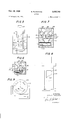
- FIGURE l is a pictorial view of a switch structure provide-d in accordance with the invention.
- FIGURE 2 is a pictorial view of an entire bank of switches provided in accordance with the invention.
- FIGURE 3 is a side view, partially in longitudinal section, of a preferred embodiment of the invention.
- FIGURE 4 is an end view of the switch of FIG. 3, with a section of the housing removed;
- FIGURE 5 is a view similar to that of FIG. 4, illustrating a further embodiment of the invention.
- FIGURE 6 is a top view, partially in section, illustrating a logical component provided in accordance with the invention.
- FIGURE 7 is a view similar to that of FIG. 6 illustrating a further type of logical component provided in accordance with the invention.
- FIGURE 8 illustrates a variant whereby the shape of the output wave form is controlled
- FIGURE 9 illustrates diagrammatically a further embodiment of the invention.
- FIG. 1 illustrates, in pictorial view, a self-contained switch structure provided in accordance with the invention.
- this structure comprises a housing or block 10 wherein the active elements of the switch are supported, the switch being provided with power by means of leads 12 andbeing controlled by means of a key 14.
- FIG. 2 illustrates how the switch structure of FIG. l is readily incorporated into a bank of switches which, in turn, is readily incorporated into a keyboard of a typewriter or data input apparatus, or the like.
- FIG. 2 is generally indicated ⁇ a support 16 on which are mounted switches 18, 20, 22 and 24 operated by keys 26 and supplied with power via a cable 28.
- FIGS. 3 and 4 illustrate the structural details of a switch of the type shown pictorially in FIGS. 1 and 2.
- FIGS. 3 and 4 generally comprises a source of radiated or radiant energy 30, a means 32 responsive to radiant energy of the type generated by source 30, and a means 34 for selectively shielding and/ or exposing means 32 with respect to source 30.
- Source 30 is preferably a light source or light generating means.
- the sour-ce 30 can be a conventional miniature incandescent bulb or the like.
- the source 30 is, by way of example, a twenty-four volt incandescent bulb. This bulb is actually operated in practice at twelve volts in order to increase the life of said source whereby failure of the source becomes an insignificant factor.
- Means 32 is a device which is responsive to radiant energy of the type provided by source 30.
- source 30 is a light generating device
- means 32 is a light responsive element such as a photoelectric cell or a photoconductor.
- Such devices are conventionally available .and may, for example, be selected from a class of photoconductors employing a light senstive material such as CdSe.
- Photoconduotor type CL603AL (Clairex) is an example.
- Means 34 is a radiant energy intercepting device such as a shutter made of a material impermeable to the type of energy provided by source 30.
- source 30 is a light generating device
- means 34 is a shutter impermeable to light other than as will be indicated hereinafter.
- Elements 30, 32 and 34 are generally positioned and supported in substantially iixed attitude as a small portable unit by ⁇ a means 36 consisting of sections 38 and 49. Sections 38 and 40 are adapted for being aligned on a common longitudinal axis 42 in face-to-face relation.
- Section 38 is provided with a bore or receptacle 44 for accommodating energy responsive means 32, whereas sec tion 40 is provided with a bore or receptacle 46 adapted for accommodating source 30.
- Sections 3S and 40 are provided with coaxial passages 48 and 5t) by means of which bores 44 and 46 are exposed to one another. Further, in one of the mu-tually engaged faces of sections 38 or 48, there is provided a slot S2 arranged between bores 44 and 46, as well as in intersecting relationship with passages 48 and 50. Slot 52 constitutes a guideway or slideway for shutter 34, the shutter 34 being vertically displaceable in said slot.
- pass-age 48 The shape of pass-age 48 and its position relative to bore 44 is best seen in FIG. 4 wherein it may be noted that shutter 34 is additionally provi-ded with lateral extensions 54 and 56, the breadth of which exceeds the width of slot 52 so that the shutter 34 is effectively locked to supporting means 36.
- Slot 52 opens downwardly into a transverse slot or opening 58 wherein are accommodated lateral extensions 56.
- the length of slot 52 is less than the distance between lateral extensions S4 and 56 to permit a determinable displacement in a vertical direction of the shutter 34.
- a resilient member 62 having the form of a leaf spring fabricated, for example, of spring steel.
- Resilient member 62 engages shutter 34 at the bottom thereof and yieldably maintains the same in a normal position of rest, extending most fully from block 1t) with the lateral extensions 56 ⁇ abutting against the upper limits of slot 58.
- Resilient member 62 may be omitted under certain circumstances and the shutter returned to rest position gravitationally if the switch is mounted in inverted position,
- Shutter 34 is provided with a light passage or window 64 of rectangular shape.
- the displacement of window 64 downwardly to correspond with the position of passages 48 and 52 provides for the passage of radiant energy from source 30 to radiant energy responsive device 32.
- device 32 is selectively exposed to or shielded from source 30 in accordance with the positioning of window 64 and thus in accordance with the position of shutter 34.
- the window and passage are shaped and relatively displaced so that small accidental movements of the shutter will be ineffective.
- a key 66 In the embodiment illustrated there is mounted atop shutter 34, a key 66, the depression of which overcomes the resistance of spring 62 and causes a displacement of the shutter 34 as aforesaid.
- the key may be replaced by cam mechanisms and so forth.
- Sections 36 and 38 cooperatively consti-tute a block or housing preferably fabricated from a material adapted for efficient heat conduction.
- This material may, for example, be aluminum or the like, but may alternatively be of other materials such as plastic or the like having sufficient structural strength where the dissipation of heat is not a consideration.
- a switching operation or a change of electrical state is effected by mechanical forces applied to key 66, such forces causing a displacement of shutter 34 -and a selective exposing of device 32 to source 30.
- Device 32 when, for example, constituted by a photoconductor or the like generally possesses a Characteristic resistance which is altered when the photoconductor is exposed to light in accordance with well known theory.
- the invention provides a device adapted for changing electrical states in response to mechanical forces.
- FIGS. 3 and 4 employs a single window 64 or rectangular shape in operative association with a passage such as the passage 48 in FIG. 4.
- the relative size of these openings militates in favor of a sharp and precise switching action.
- thc structure which has been described is notably free of disturbance by dust, dirt and tarnishing as is harmful in conventional switches employing selectively engaging contacts.
- the structure described is capable of operation with optimum reliability and is substantially inertialcss.
- the resistance of this switch in an electric circuit is substantially constant and is thus predictable over prolonged periods of use as compared with conventional switches wherein the resistance varies as the switch contacts tarnish orotherwisc deteriorate.
- the switch of the invention will, moreover, not arc over or suffer from similar defective types of operation.
- FIG. 5 illustrates a transfer switch provided in accordance with the invention.
- a shutter 68 slidable in a section 70.
- Section 70 houses two photoconductor or light responsive devices 72 and 74 Which are operatively associated with a light source (not shown) spaced from these light responsive devices as in the prior embodimen-t. Passages 76 and 78 lead respectively to light responsive devices 72 and 74.
- shutter 68 is provided with two windows or openings 80 and 82.
- Windows 80 and 82 are spaced by a distance which is different from the distance separating devices 72 and 74. This arrangement is such that only one of the devices 72 or 74 will be exposed to the associated light source at a given time.
- window 88 comes into registration with passage 76 and exposes device 72 to the light source.
- window 82 moves out of alignment with passage 78 and the light source is then isolated from the light responsive device 74.
- the structure illustrated tin FIG. 5 constitutes a transfer switch inasmuch as only one of the devices 72 or 74 is actuated at a given time and the function thereof is selectively transferred from one device to the other as well as between the circuits (not shown) connected to these devices.
- FIG. 6 illustrates a logical component provided in accordance with a further embodiment of the invention.
- this local component is an and element. Stated otheuwise, it is the function of the switch of FIG. 6 to exhibit a change of state in response to t-he simultaneous application of two separate and distinct mechanical forces.
- FIG. 6 are diiagrammatically illustrated a light source 84 and a light responsive device 86, these elements ybeing adapted for exposure to one another by means of passages 88 and 90.
- two shutters 92 and 94 are provided, each having formed therein a window 96 or 98 respectively.
- Shutter 92 is displaceable vertically relative to the plane of the drawing in order to move window 96 into alignment with passages 88 and 90.
- Shutter 94 is displaceable as indicated by arrow 100 in order to move window 98 selectively into or out of registration with passages 88 and 90.
- FIG. 6 is a logical and component responsive to the simultaneuos applicat-ion of separatel mechanical forces to effect a change of state or a switching operation.
- FIG. 7 is a logical or component. This component responds to the application or any one of a plurality of forces to generate an output signal exhibited as, or controlled by, the change of state in light responsive device 1012.
- This component responds to the application or any one of a plurality of forces to generate an output signal exhibited as, or controlled by, the change of state in light responsive device 1012.
- Directed at light responsive device is a pyrimidal or conically shaped opening or passage i116 with Which are aligned passages 118, 120 and 122 corresponding to light sources 104, 106 and 108.
- FIG. 7 is a logical or component which exhibits a change o-f state in response to the application thereto of one of a number of possible mechanical forces.
- output wave forms can be readily controlled by steps taken during the fabrication of the switch. As will be next indicated hereinunder, this control is effected by judicious selection of Ithe coniguration of the window provided in the shutter.
- the amount of light to which a photoelectric cell or photoconductor is exposed controls the characteristic exhibited thereby.
- the rate of change of the light intensity to which the photoelectric cell is exposed can be controlled by the shape of Window or opening employed in the shutter of the particular switch under consideration.
- a specific shutter 124 is illustrated in FIG. 8, with a window 126 being provided in this shutter.
- the window is provided at its cutting or leading edge 128 with a particular configuration adapted for controlling the rate of exposure of the associated light responsive device to the associated light source to obtain a particular type of output signal.
- square, saw-tooth and sinusoidal output signals may be obtained.
- FIG. 9 is illustrated another of the many types of shutters which may be employed, there being illustrated in this figure ⁇ a rotary disc 130 rotatable on a pin 132, the disc being provided with la plurality of openings 134 by means of which a light responsive device 136 is exposed to a light source (not shown).
- a preferred method in accordance with the invention comprises forming complementary block sections adapted for being juxtaposed in face-toeface relation along a common longitudinal axis and forming bores in each section and passages connected to the bores and in turn having a common axis with the block sections aligned on said longitudinal axis.
- This method further comprises forming a slot in one of the juxtaposed faces, the slot being arranged in intersect-ing relationship With the second said axis.
- the method comprises placing a shutter in the slot with a light source and a light responsive element being respectively positioned in the bores.
- a second slot (such as the slot 58 of FIGS. 3 and 4) is arranged transversely of ⁇ the first said slot, transverse extension being formed on the shutter for accommodation in the second slot ywhereby the shutter is locked to the block.
- the method contemplates mounting a resilient member on one of the sections to engages the shutter and yieldingly resist displacement thereof.
- a switch comprising a substantially solid block defining spaced receptacles and a passage connecting said receptacles, said block being further provided with an elongated rectilinear interior slideway of predetermined length and breadth, said slideway being located between said receptacles and in intersecting relationship with said passage, a light source in one of said receptacles, a light responsive element in the other of said receptacles, said light source being adapted for transmitting light via said passage to said light responsive element, a light intercepting element rectilinearly displaceable in said slideway between a normal position of rest and an active position for selectively blocking light transmitted by said source, said light intercepting element being supported by said block and extending externally thereof, and means within said block engaging the light intercepting element and yieldably holding the same in said normal position of rest in which the light interception element extends most fully from the said block, said light intercepting element comprising an elongated member in said slideway and means extending laterally on said passage
- a switch as claimed in claim 1 wherein the first said means comprises at least one spring mounted within said block and engaging said light intercepting element.
- a switch as claimed in claim 1 wherein the second said means comprises lateral extensions on said elongated member.
- a switch as claimed in claim 1 wherein the second said means comprises a key mounted on said elongated member externally of said block.
- a switch as claimed in claim 1 comprising additional light sources in said block and additional light intercepting elements adapted for selectively exposing the light responsive element to the latter said light sources.
- a switch as claimed in claim 1 comprising a further light intercepting element interposed between said light source and light responsive element.
Description
Claims (1)
Priority Applications (1)
| Application Number | Priority Date | Filing Date | Title |
|---|---|---|---|
| US105101A US3235741A (en) | 1961-04-24 | 1961-04-24 | Switch |
Applications Claiming Priority (1)
| Application Number | Priority Date | Filing Date | Title |
|---|---|---|---|
| US105101A US3235741A (en) | 1961-04-24 | 1961-04-24 | Switch |
Publications (1)
| Publication Number | Publication Date |
|---|---|
| US3235741A true US3235741A (en) | 1966-02-15 |
Family
ID=22304023
Family Applications (1)
| Application Number | Title | Priority Date | Filing Date |
|---|---|---|---|
| US105101A Expired - Lifetime US3235741A (en) | 1961-04-24 | 1961-04-24 | Switch |
Country Status (1)
| Country | Link |
|---|---|
| US (1) | US3235741A (en) |
Cited By (79)
| Publication number | Priority date | Publication date | Assignee | Title |
|---|---|---|---|---|
| US3336482A (en) * | 1964-06-19 | 1967-08-15 | Square D Co | Plunger operated photoelectric switch convertible from normally on to normally off |
| US3363106A (en) * | 1964-06-26 | 1968-01-09 | Seeburg Corp | Photo-conductor potential divider |
| US3377485A (en) * | 1964-01-28 | 1968-04-09 | Fujitsu Ltd | Photomechanical code keyboard unit |
| US3526776A (en) * | 1966-11-30 | 1970-09-01 | Hiroshi Mizukoshi | Photoelectric detecting device for weft in shuttle under operation |
| US3579047A (en) * | 1968-02-13 | 1971-05-18 | Diehl Fa | Keyboard using switches having light obstructing elements |
| US3610939A (en) * | 1970-03-19 | 1971-10-05 | Gri Computer Corp | Electrooptical switch structure |
| US3628033A (en) * | 1969-08-19 | 1971-12-14 | Jean Francois Taillens | Photoelectric time delay lock |
| US3628024A (en) * | 1970-04-13 | 1971-12-14 | Holley Carburetor Co | Photo-optic transducer using apertured shade and moveable shutter |
| US3628037A (en) * | 1968-07-26 | 1971-12-14 | Omron Tateisi Electronics Co | Photoelectric switch unit |
| US3670170A (en) * | 1971-03-15 | 1972-06-13 | John M Stevens | Non-visible electromagnetic radiation measuring device |
| US3783274A (en) * | 1972-04-06 | 1974-01-01 | H Towne | Solid-state switch |
| US3851328A (en) * | 1973-01-17 | 1974-11-26 | Singer Co | Optical solid state switches |
| US3906222A (en) * | 1973-11-22 | 1975-09-16 | France Etat | Electrical push-button switch with photo-electrical switching elements |
| US3949219A (en) * | 1975-01-20 | 1976-04-06 | Optron, Inc. | Optical micro-switch |
| US4146856A (en) * | 1977-12-29 | 1979-03-27 | Cutler-Hammer, Inc. | Shutterless fiber optic switch |
| US4215596A (en) * | 1978-12-18 | 1980-08-05 | Long Leonard C | Gear shift lever assembly having ignition system deenergizing means |
| US4223217A (en) * | 1977-05-12 | 1980-09-16 | Eaton Corporation | Fiber optic electric switch |
| US4348122A (en) * | 1980-10-23 | 1982-09-07 | Balta Justin O | Shift lock and position indicating torsion spring activated key switch |
| USRE31579E (en) * | 1977-12-29 | 1984-05-01 | Eaton Corporation | Shutterless fiber optic switch |
| US4795900A (en) * | 1986-03-27 | 1989-01-03 | Sadao Kokubu | Optical switch device employing a fluorescent substance with a radioactive element as a light source |
| US5303921A (en) * | 1992-12-31 | 1994-04-19 | Shuffle Master, Inc. | Jammed shuffle detector |
| US20020063389A1 (en) * | 1994-08-09 | 2002-05-30 | Breeding John G. | Card shuffler with sequential card feeding module and method of delivering groups of cards |
| US20020163125A1 (en) * | 1998-04-15 | 2002-11-07 | Shuffle Master, Inc. | Device and method for continuously shuffling and monitoring cards for specialty games |
| US20030052449A1 (en) * | 1998-04-15 | 2003-03-20 | Attila Grauzer | Device and method for continuously shuffling and monitoring cards |
| US20030073498A1 (en) * | 2001-09-28 | 2003-04-17 | Shuffle Master, Inc. | Card shuffling apparatus with automatic card size calibration |
| US20030075866A1 (en) * | 2001-10-19 | 2003-04-24 | Card-Casinos Austria R&D-Casinos Austria Forschungs-Und Entwicklungsges, M.B.H. | Card shuffler |
| US20030090059A1 (en) * | 1998-04-15 | 2003-05-15 | Attila Grauzer | Device and method for continuously shuffling and monitoring cards |
| US6568678B2 (en) | 1994-08-09 | 2003-05-27 | Shuffle Master, Inc. | Method and apparatus for automatically cutting and shuffling playing cards |
| US6651982B2 (en) | 2001-09-28 | 2003-11-25 | Shuffle Master, Inc. | Card shuffling apparatus with integral card delivery |
| US20040067789A1 (en) * | 2001-09-28 | 2004-04-08 | Shuffle Master, Inc. | Card shuffler with card rank and value reading capability |
| US20050051956A1 (en) * | 1998-04-15 | 2005-03-10 | Shuffle Master, Inc. | Hand forming shuffler with on demand hand delivery |
| US20050061618A1 (en) * | 2000-11-09 | 2005-03-24 | Osterfeld Gary J. | Apparatus for manufacturing filter cartridges, and method of using same |
| US20050104290A1 (en) * | 2001-09-28 | 2005-05-19 | Shuffle Master, Inc. | Multiple mode card shuffler and card reading device |
| US20050113166A1 (en) * | 2003-07-17 | 2005-05-26 | Shuffle Master, Inc. | Discard rack with card reader for playing cards |
| US20050140090A1 (en) * | 1994-08-09 | 2005-06-30 | Shuffle Master, Inc. | Card shuffler with jam recovery and display |
| US20060066048A1 (en) * | 2004-09-14 | 2006-03-30 | Shuffle Master, Inc. | Magnetic jam detection in a card shuffler |
| US20060281534A1 (en) * | 2001-09-28 | 2006-12-14 | Shuffle Master, Inc. | Card shuffling apparatus with automatic card size calibration during shuffling |
| US20070069462A1 (en) * | 2005-06-13 | 2007-03-29 | Shuffle Master, Inc. | Card shuffler with card rank and value reading capability using CMOS sensor |
| US7255344B2 (en) | 1998-04-15 | 2007-08-14 | Shuffle Master, Inc. | Device and method for continuously shuffling and monitoring cards |
| US7261294B2 (en) | 2005-02-14 | 2007-08-28 | Shuffle Master, Inc. | Playing card shuffler with differential hand count capability |
| US20070267811A1 (en) * | 2006-05-17 | 2007-11-22 | Shuffle Master, Inc. | Playing card delivery for games with multiple dealing rounds |
| US20070278739A1 (en) * | 2006-05-31 | 2007-12-06 | Shuffle Master, Inc. | Card weight for gravity feed input for playing card shuffler |
| US20080006997A1 (en) * | 2006-07-05 | 2008-01-10 | Shuffle Master, Inc. | Card shuffler with adjacent card infeed and card output compartments |
| US20080006998A1 (en) * | 2006-07-05 | 2008-01-10 | Attila Grauzer | Card handling devices and methods of using the same |
| US20080303210A1 (en) * | 2007-06-06 | 2008-12-11 | Attila Grauzer | Apparatus, system, method, and computer-readable medium for casino card handling with multiple hand recall feature |
| US20090189346A1 (en) * | 2000-04-12 | 2009-07-30 | Peter Krenn | Swivel mounted card handing device |
| US20110109042A1 (en) * | 2006-05-31 | 2011-05-12 | Rynda Robert J | Automatic system and methods for accurate card handling |
| US7976023B1 (en) | 2002-02-08 | 2011-07-12 | Shuffle Master, Inc. | Image capturing card shuffler |
| US8011661B2 (en) | 2001-09-28 | 2011-09-06 | Shuffle Master, Inc. | Shuffler with shuffling completion indicator |
| US8490973B2 (en) | 2004-10-04 | 2013-07-23 | Shfl Entertainment, Inc. | Card reading shoe with card stop feature and systems utilizing the same |
| US8511684B2 (en) | 2004-10-04 | 2013-08-20 | Shfl Entertainment, Inc. | Card-reading shoe with inventory correction feature and methods of correcting inventory |
| US8590896B2 (en) | 2000-04-12 | 2013-11-26 | Shuffle Master Gmbh & Co Kg | Card-handling devices and systems |
| US9233298B2 (en) | 2009-04-07 | 2016-01-12 | Bally Gaming, Inc. | Playing card shuffler |
| US9266011B2 (en) | 1997-03-13 | 2016-02-23 | Bally Gaming, Inc. | Card-handling devices and methods of using such devices |
| US9320964B2 (en) | 2006-11-10 | 2016-04-26 | Bally Gaming, Inc. | System for billing usage of a card handling device |
| US9345952B2 (en) | 2006-03-24 | 2016-05-24 | Shuffle Master Gmbh & Co Kg | Card handling apparatus |
| US9345951B2 (en) | 2001-09-28 | 2016-05-24 | Bally Gaming, Inc. | Methods and apparatuses for an automatic card handling device and communication networks including same |
| US9378766B2 (en) | 2012-09-28 | 2016-06-28 | Bally Gaming, Inc. | Card recognition system, card handling device, and method for tuning a card handling device |
| USD764599S1 (en) | 2014-08-01 | 2016-08-23 | Bally Gaming, Inc. | Card shuffler device |
| US9452346B2 (en) | 2001-09-28 | 2016-09-27 | Bally Gaming, Inc. | Method and apparatus for using upstream communication in a card shuffler |
| US9474957B2 (en) | 2014-05-15 | 2016-10-25 | Bally Gaming, Inc. | Playing card handling devices, systems, and methods for verifying sets of cards |
| US9504905B2 (en) | 2014-09-19 | 2016-11-29 | Bally Gaming, Inc. | Card shuffling device and calibration method |
| US9511274B2 (en) | 2012-09-28 | 2016-12-06 | Bally Gaming Inc. | Methods for automatically generating a card deck library and master images for a deck of cards, and a related card processing apparatus |
| US9539494B2 (en) | 2009-04-07 | 2017-01-10 | Bally Gaming, Inc. | Card shuffling apparatuses and related methods |
| US9566501B2 (en) | 2014-08-01 | 2017-02-14 | Bally Gaming, Inc. | Hand-forming card shuffling apparatuses including multi-card storage compartments, and related methods |
| US9713761B2 (en) | 2011-07-29 | 2017-07-25 | Bally Gaming, Inc. | Method for shuffling and dealing cards |
| US9731190B2 (en) | 2011-07-29 | 2017-08-15 | Bally Gaming, Inc. | Method and apparatus for shuffling and handling cards |
| US9802114B2 (en) | 2010-10-14 | 2017-10-31 | Shuffle Master Gmbh & Co Kg | Card handling systems, devices for use in card handling systems and related methods |
| US9849368B2 (en) | 2012-07-27 | 2017-12-26 | Bally Gaming, Inc. | Batch card shuffling apparatuses including multi card storage compartments |
| US9993719B2 (en) | 2015-12-04 | 2018-06-12 | Shuffle Master Gmbh & Co Kg | Card handling devices and related assemblies and components |
| US10279245B2 (en) | 2014-04-11 | 2019-05-07 | Bally Gaming, Inc. | Method and apparatus for handling cards |
| US10339765B2 (en) | 2016-09-26 | 2019-07-02 | Shuffle Master Gmbh & Co Kg | Devices, systems, and related methods for real-time monitoring and display of related data for casino gaming devices |
| US10933300B2 (en) | 2016-09-26 | 2021-03-02 | Shuffle Master Gmbh & Co Kg | Card handling devices and related assemblies and components |
| US11127546B2 (en) * | 2019-05-14 | 2021-09-21 | Chicony Electronics Co., Ltd. | Keyboard |
| US11173383B2 (en) | 2019-10-07 | 2021-11-16 | Sg Gaming, Inc. | Card-handling devices and related methods, assemblies, and components |
| US11338194B2 (en) | 2018-09-28 | 2022-05-24 | Sg Gaming, Inc. | Automatic card shufflers and related methods of automatic jam recovery |
| US11376489B2 (en) | 2018-09-14 | 2022-07-05 | Sg Gaming, Inc. | Card-handling devices and related methods, assemblies, and components |
| US11898837B2 (en) | 2019-09-10 | 2024-02-13 | Shuffle Master Gmbh & Co Kg | Card-handling devices with defect detection and related methods |
| US11896891B2 (en) | 2018-09-14 | 2024-02-13 | Sg Gaming, Inc. | Card-handling devices and related methods, assemblies, and components |
Citations (12)
| Publication number | Priority date | Publication date | Assignee | Title |
|---|---|---|---|---|
| US2100934A (en) * | 1936-02-05 | 1937-11-30 | Eclipse Aviat Corp | Aircraft |
| US2160603A (en) * | 1937-09-01 | 1939-05-30 | Richard G Sagebeer | Comparometer |
| US2265149A (en) * | 1941-01-27 | 1941-12-09 | Carl J Crane | Photoelectric device for opening or closing a switch at any selected altitude |
| US2342245A (en) * | 1942-06-27 | 1944-02-22 | Bell Telephone Labor Inc | Electric signaling |
| US2408754A (en) * | 1944-07-27 | 1946-10-08 | Teleregister Corp | Photoelectric transmitting typewriter apparatus |
| US2438825A (en) * | 1945-06-16 | 1948-03-30 | Trans Lux Corp | Selector |
| US2872590A (en) * | 1954-11-12 | 1959-02-03 | Wilkata Codes Inc | Photoelectric scanning device |
| US2920209A (en) * | 1957-09-25 | 1960-01-05 | Melpar Inc | Photoelectric device |
| US2998530A (en) * | 1958-01-23 | 1961-08-29 | Ncr Co | Switching device |
| US3011379A (en) * | 1957-02-05 | 1961-12-05 | Baldwin Piano Co | Electronic musical instrument with photoelectric switching |
| US3023318A (en) * | 1960-01-27 | 1962-02-27 | John H Jones | Optical switching |
| US3102227A (en) * | 1957-03-09 | 1963-08-27 | Philips Corp | Arrangement for deriving an adjustable partial voltage from an electric signal voltage |
-
1961
- 1961-04-24 US US105101A patent/US3235741A/en not_active Expired - Lifetime
Patent Citations (12)
| Publication number | Priority date | Publication date | Assignee | Title |
|---|---|---|---|---|
| US2100934A (en) * | 1936-02-05 | 1937-11-30 | Eclipse Aviat Corp | Aircraft |
| US2160603A (en) * | 1937-09-01 | 1939-05-30 | Richard G Sagebeer | Comparometer |
| US2265149A (en) * | 1941-01-27 | 1941-12-09 | Carl J Crane | Photoelectric device for opening or closing a switch at any selected altitude |
| US2342245A (en) * | 1942-06-27 | 1944-02-22 | Bell Telephone Labor Inc | Electric signaling |
| US2408754A (en) * | 1944-07-27 | 1946-10-08 | Teleregister Corp | Photoelectric transmitting typewriter apparatus |
| US2438825A (en) * | 1945-06-16 | 1948-03-30 | Trans Lux Corp | Selector |
| US2872590A (en) * | 1954-11-12 | 1959-02-03 | Wilkata Codes Inc | Photoelectric scanning device |
| US3011379A (en) * | 1957-02-05 | 1961-12-05 | Baldwin Piano Co | Electronic musical instrument with photoelectric switching |
| US3102227A (en) * | 1957-03-09 | 1963-08-27 | Philips Corp | Arrangement for deriving an adjustable partial voltage from an electric signal voltage |
| US2920209A (en) * | 1957-09-25 | 1960-01-05 | Melpar Inc | Photoelectric device |
| US2998530A (en) * | 1958-01-23 | 1961-08-29 | Ncr Co | Switching device |
| US3023318A (en) * | 1960-01-27 | 1962-02-27 | John H Jones | Optical switching |
Cited By (218)
| Publication number | Priority date | Publication date | Assignee | Title |
|---|---|---|---|---|
| US3377485A (en) * | 1964-01-28 | 1968-04-09 | Fujitsu Ltd | Photomechanical code keyboard unit |
| US3336482A (en) * | 1964-06-19 | 1967-08-15 | Square D Co | Plunger operated photoelectric switch convertible from normally on to normally off |
| US3363106A (en) * | 1964-06-26 | 1968-01-09 | Seeburg Corp | Photo-conductor potential divider |
| US3526776A (en) * | 1966-11-30 | 1970-09-01 | Hiroshi Mizukoshi | Photoelectric detecting device for weft in shuttle under operation |
| US3579047A (en) * | 1968-02-13 | 1971-05-18 | Diehl Fa | Keyboard using switches having light obstructing elements |
| US3628037A (en) * | 1968-07-26 | 1971-12-14 | Omron Tateisi Electronics Co | Photoelectric switch unit |
| US3628033A (en) * | 1969-08-19 | 1971-12-14 | Jean Francois Taillens | Photoelectric time delay lock |
| US3610939A (en) * | 1970-03-19 | 1971-10-05 | Gri Computer Corp | Electrooptical switch structure |
| US3628024A (en) * | 1970-04-13 | 1971-12-14 | Holley Carburetor Co | Photo-optic transducer using apertured shade and moveable shutter |
| US3670170A (en) * | 1971-03-15 | 1972-06-13 | John M Stevens | Non-visible electromagnetic radiation measuring device |
| US3783274A (en) * | 1972-04-06 | 1974-01-01 | H Towne | Solid-state switch |
| US3851328A (en) * | 1973-01-17 | 1974-11-26 | Singer Co | Optical solid state switches |
| US3906222A (en) * | 1973-11-22 | 1975-09-16 | France Etat | Electrical push-button switch with photo-electrical switching elements |
| US3949219A (en) * | 1975-01-20 | 1976-04-06 | Optron, Inc. | Optical micro-switch |
| US4223217A (en) * | 1977-05-12 | 1980-09-16 | Eaton Corporation | Fiber optic electric switch |
| US4146856A (en) * | 1977-12-29 | 1979-03-27 | Cutler-Hammer, Inc. | Shutterless fiber optic switch |
| USRE31579E (en) * | 1977-12-29 | 1984-05-01 | Eaton Corporation | Shutterless fiber optic switch |
| US4215596A (en) * | 1978-12-18 | 1980-08-05 | Long Leonard C | Gear shift lever assembly having ignition system deenergizing means |
| US4348122A (en) * | 1980-10-23 | 1982-09-07 | Balta Justin O | Shift lock and position indicating torsion spring activated key switch |
| US4795900A (en) * | 1986-03-27 | 1989-01-03 | Sadao Kokubu | Optical switch device employing a fluorescent substance with a radioactive element as a light source |
| US4871909A (en) * | 1986-03-27 | 1989-10-03 | Kabushiki Kaisha Tokai Rika Denki Seisakusho | Optical switch device employing fluorescent substance in combination with a radioactive element as a light source |
| US5303921A (en) * | 1992-12-31 | 1994-04-19 | Shuffle Master, Inc. | Jammed shuffle detector |
| US20020063389A1 (en) * | 1994-08-09 | 2002-05-30 | Breeding John G. | Card shuffler with sequential card feeding module and method of delivering groups of cards |
| US7584962B2 (en) | 1994-08-09 | 2009-09-08 | Shuffle Master, Inc. | Card shuffler with jam recovery and display |
| US20050140090A1 (en) * | 1994-08-09 | 2005-06-30 | Shuffle Master, Inc. | Card shuffler with jam recovery and display |
| US6568678B2 (en) | 1994-08-09 | 2003-05-27 | Shuffle Master, Inc. | Method and apparatus for automatically cutting and shuffling playing cards |
| US9266011B2 (en) | 1997-03-13 | 2016-02-23 | Bally Gaming, Inc. | Card-handling devices and methods of using such devices |
| US9370710B2 (en) | 1998-04-15 | 2016-06-21 | Bally Gaming, Inc. | Methods for shuffling cards and rack assemblies for use in automatic card shufflers |
| US8646779B2 (en) | 1998-04-15 | 2014-02-11 | Shfl Entertainment, Inc. | Device and method for handling, shuffling, and moving cards |
| US20030090059A1 (en) * | 1998-04-15 | 2003-05-15 | Attila Grauzer | Device and method for continuously shuffling and monitoring cards |
| US9561426B2 (en) | 1998-04-15 | 2017-02-07 | Bally Gaming, Inc. | Card-handling devices |
| US20080203658A1 (en) * | 1998-04-15 | 2008-08-28 | Shuffle Master, Inc. | Device and method for continuously shuffling and monitoring cards |
| US9266012B2 (en) | 1998-04-15 | 2016-02-23 | Bally Gaming, Inc. | Methods of randomizing cards |
| US9861881B2 (en) | 1998-04-15 | 2018-01-09 | Bally Gaming, Inc. | Card handling apparatuses and methods for handling cards |
| US20040245720A1 (en) * | 1998-04-15 | 2004-12-09 | Attila Grauzer | Device and method for continuously shuffling and monitoring cards for specialty games |
| US7413191B2 (en) | 1998-04-15 | 2008-08-19 | Shuffle Master, Inc. | Device and method for forming and delivering hands from randomly arranged decks of playing cards |
| US20050051956A1 (en) * | 1998-04-15 | 2005-03-10 | Shuffle Master, Inc. | Hand forming shuffler with on demand hand delivery |
| US20050062229A1 (en) * | 1998-04-15 | 2005-03-24 | Attila Grauzer | Device and method for continuously shuffling and monitoring cards |
| US7523936B2 (en) | 1998-04-15 | 2009-04-28 | Shuffle Master, Inc. | Device and method for forming and delivering hands from randomly arranged decks of playing cards |
| US20050093231A1 (en) * | 1998-04-15 | 2005-05-05 | Attila Grauzer | Device and method for continuously shuffling and monitoring cards |
| US20050093230A1 (en) * | 1998-04-15 | 2005-05-05 | Attila Grauzer | Device and method for continuously shuffling and monitoring cards |
| US8998211B2 (en) | 1998-04-15 | 2015-04-07 | Bally Gaming, Inc. | Methods of randomizing cards |
| US8820745B2 (en) | 1998-04-15 | 2014-09-02 | Shfl Entertainment, Inc. | Device and method for handling, shuffling, and moving cards |
| US7338044B2 (en) | 1998-04-15 | 2008-03-04 | Shuffle Master, Inc. | Card shuffler with user game selection input |
| US20030052449A1 (en) * | 1998-04-15 | 2003-03-20 | Attila Grauzer | Device and method for continuously shuffling and monitoring cards |
| US20050146093A1 (en) * | 1998-04-15 | 2005-07-07 | Shuffle Master, Inc. | Card shuffler with user game selection input |
| US20030094756A1 (en) * | 1998-04-15 | 2003-05-22 | Attila Grauzer | Device and method for continuously shuffling and monitoring cards |
| US7322576B2 (en) | 1998-04-15 | 2008-01-29 | Shuffle Master, Inc. | Device and method for continuously shuffling and monitoring cards |
| US7059602B2 (en) | 1998-04-15 | 2006-06-13 | Shuffle Master, Inc. | Card shuffler with staging area for collecting groups of cards |
| US20060145417A1 (en) * | 1998-04-15 | 2006-07-06 | Attila Grauzer | Device and method for forming and delivering hands from randomly arranged decks of playing cards |
| US7073791B2 (en) | 1998-04-15 | 2006-07-11 | Shuffle Master, Inc. | Hand forming shuffler with on demand hand delivery |
| US7137627B2 (en) | 1998-04-15 | 2006-11-21 | Attila Grauzer | Device and method for continuously shuffling and monitoring cards |
| US8505916B2 (en) | 1998-04-15 | 2013-08-13 | Shfl Entertainment, Inc. | Methods of randomizing cards |
| US8210535B2 (en) | 1998-04-15 | 2012-07-03 | Shuffle Master, Inc. | Device and method for continuously shuffling and monitoring cards |
| US7234698B2 (en) | 1998-04-15 | 2007-06-26 | Shuffle Master, Inc. | Device and method for continuously shuffling and monitoring cards |
| US7255344B2 (en) | 1998-04-15 | 2007-08-14 | Shuffle Master, Inc. | Device and method for continuously shuffling and monitoring cards |
| US8191894B2 (en) | 1998-04-15 | 2012-06-05 | Shuffle Master, Inc. | Card feed mechanisms for card-handling apparatuses and related methods |
| US20020163125A1 (en) * | 1998-04-15 | 2002-11-07 | Shuffle Master, Inc. | Device and method for continuously shuffling and monitoring cards for specialty games |
| US20110006480A1 (en) * | 1998-04-15 | 2011-01-13 | Attila Grauzer | Card feed mechanism for card handling device |
| US7784790B2 (en) | 1998-04-15 | 2010-08-31 | Shuffle Master, Inc | Device and method for continuously shuffling and monitoring cards |
| US7946586B2 (en) | 2000-04-12 | 2011-05-24 | Shuffle Master Gmbh & Co Kg | Swivel mounted card handling device |
| US20090189346A1 (en) * | 2000-04-12 | 2009-07-30 | Peter Krenn | Swivel mounted card handing device |
| US8590896B2 (en) | 2000-04-12 | 2013-11-26 | Shuffle Master Gmbh & Co Kg | Card-handling devices and systems |
| US10456659B2 (en) | 2000-04-12 | 2019-10-29 | Shuffle Master Gmbh & Co Kg | Card handling devices and systems |
| US9126103B2 (en) | 2000-04-12 | 2015-09-08 | Shuffle Master Gmbh & Co Kg | Card-handling devices and systems |
| US20050061618A1 (en) * | 2000-11-09 | 2005-03-24 | Osterfeld Gary J. | Apparatus for manufacturing filter cartridges, and method of using same |
| US8651485B2 (en) | 2001-09-28 | 2014-02-18 | Shfl Entertainment, Inc. | Playing card handling devices including shufflers |
| US6651982B2 (en) | 2001-09-28 | 2003-11-25 | Shuffle Master, Inc. | Card shuffling apparatus with integral card delivery |
| US7523935B2 (en) | 2001-09-28 | 2009-04-28 | Shuffle Master, Inc. | Card shuffling apparatus with integral card delivery |
| US7384044B2 (en) | 2001-09-28 | 2008-06-10 | Shuffle Master, Inc | Card shuffling apparatus with automatic card size calibration |
| US20030073498A1 (en) * | 2001-09-28 | 2003-04-17 | Shuffle Master, Inc. | Card shuffling apparatus with automatic card size calibration |
| US10532272B2 (en) | 2001-09-28 | 2020-01-14 | Bally Gaming, Inc. | Flush mounted card shuffler that elevates cards |
| US7677565B2 (en) | 2001-09-28 | 2010-03-16 | Shuffle Master, Inc | Card shuffler with card rank and value reading capability |
| US9345951B2 (en) | 2001-09-28 | 2016-05-24 | Bally Gaming, Inc. | Methods and apparatuses for an automatic card handling device and communication networks including same |
| US7753373B2 (en) | 2001-09-28 | 2010-07-13 | Shuffle Master, Inc. | Multiple mode card shuffler and card reading device |
| US6651981B2 (en) | 2001-09-28 | 2003-11-25 | Shuffle Master, Inc. | Card shuffling apparatus with integral card delivery |
| US10549177B2 (en) | 2001-09-28 | 2020-02-04 | Bally Gaming, Inc. | Card handling devices comprising angled support surfaces |
| US20040067789A1 (en) * | 2001-09-28 | 2004-04-08 | Shuffle Master, Inc. | Card shuffler with card rank and value reading capability |
| US20100225056A1 (en) * | 2001-09-28 | 2010-09-09 | Attila Grauzer | Card shuffler with card rank and value reading capability |
| US20100276880A1 (en) * | 2001-09-28 | 2010-11-04 | Attila Grauzer | Multiple mode card shuffler and card reading device |
| US10343054B2 (en) | 2001-09-28 | 2019-07-09 | Bally Gaming, Inc. | Systems including automatic card handling apparatuses and related methods |
| US20040169332A1 (en) * | 2001-09-28 | 2004-09-02 | Attila Grauzer | Card shuffling apparatus with integral card delivery |
| US10569159B2 (en) | 2001-09-28 | 2020-02-25 | Bally Gaming, Inc. | Card shufflers and gaming tables having shufflers |
| US9452346B2 (en) | 2001-09-28 | 2016-09-27 | Bally Gaming, Inc. | Method and apparatus for using upstream communication in a card shuffler |
| US9220972B2 (en) | 2001-09-28 | 2015-12-29 | Bally Gaming, Inc. | Multiple mode card shuffler and card reading device |
| US8556263B2 (en) | 2001-09-28 | 2013-10-15 | Shfl Entertainment, Inc. | Card shuffler with card rank and value reading capability |
| US8011661B2 (en) | 2001-09-28 | 2011-09-06 | Shuffle Master, Inc. | Shuffler with shuffling completion indicator |
| US8025294B2 (en) | 2001-09-28 | 2011-09-27 | Shuffle Master, Inc. | Card shuffler with card rank and value reading capability |
| US8038521B2 (en) | 2001-09-28 | 2011-10-18 | Shuffle Master, Inc. | Card shuffling apparatus with automatic card size calibration during shuffling |
| US10226687B2 (en) | 2001-09-28 | 2019-03-12 | Bally Gaming, Inc. | Method and apparatus for using upstream communication in a card shuffler |
| US20050023752A1 (en) * | 2001-09-28 | 2005-02-03 | Atilla Grauzer | Card shuffling apparatus with automatic card size calibration |
| US10004976B2 (en) | 2001-09-28 | 2018-06-26 | Bally Gaming, Inc. | Card handling devices and related methods |
| US8944904B2 (en) | 2001-09-28 | 2015-02-03 | Bally Gaming, Inc. | Method and apparatus for card handling device calibration |
| US8899587B2 (en) | 2001-09-28 | 2014-12-02 | Bally Gaming, Inc. | Multiple mode card shuffler and card reading device |
| US20050104290A1 (en) * | 2001-09-28 | 2005-05-19 | Shuffle Master, Inc. | Multiple mode card shuffler and card reading device |
| US20060281534A1 (en) * | 2001-09-28 | 2006-12-14 | Shuffle Master, Inc. | Card shuffling apparatus with automatic card size calibration during shuffling |
| US10086260B2 (en) | 2001-09-28 | 2018-10-02 | Bally Gaming, Inc. | Method and apparatus for using upstream communication in a card shuffler |
| US10022617B2 (en) | 2001-09-28 | 2018-07-17 | Bally Gaming, Inc. | Shuffler and method of shuffling cards |
| US8419521B2 (en) | 2001-09-28 | 2013-04-16 | Shfl Entertainment, Inc. | Method and apparatus for card handling device calibration |
| US8444147B2 (en) | 2001-09-28 | 2013-05-21 | Shfl Entertainment, Inc. | Multiple mode card shuffler and card reading device |
| US7036818B2 (en) | 2001-09-28 | 2006-05-02 | Shuffle Master, Inc. | Card shuffling apparatus with automatic card size calibration |
| US20030075866A1 (en) * | 2001-10-19 | 2003-04-24 | Card-Casinos Austria R&D-Casinos Austria Forschungs-Und Entwicklungsges, M.B.H. | Card shuffler |
| US6889979B2 (en) | 2001-10-19 | 2005-05-10 | Shuffle Master Gmbh & Co Kg | Card shuffler |
| US7976023B1 (en) | 2002-02-08 | 2011-07-12 | Shuffle Master, Inc. | Image capturing card shuffler |
| US20110198804A1 (en) * | 2002-02-08 | 2011-08-18 | Lynn Hessing | Image capturing card shuffler |
| US9700785B2 (en) | 2002-02-08 | 2017-07-11 | Bally Gaming, Inc. | Card-handling device and method of operation |
| US8720891B2 (en) | 2002-02-08 | 2014-05-13 | Shfl Entertainment, Inc. | Image capturing card shuffler |
| US9333415B2 (en) | 2002-02-08 | 2016-05-10 | Bally Gaming, Inc. | Methods for handling playing cards with a card handling device |
| US10092821B2 (en) | 2002-02-08 | 2018-10-09 | Bally Technology, Inc. | Card-handling device and method of operation |
| US20100167826A1 (en) * | 2003-07-17 | 2010-07-01 | Attila Grauzer | Discard rack with card reader for playing cards |
| US20050113166A1 (en) * | 2003-07-17 | 2005-05-26 | Shuffle Master, Inc. | Discard rack with card reader for playing cards |
| US20060066048A1 (en) * | 2004-09-14 | 2006-03-30 | Shuffle Master, Inc. | Magnetic jam detection in a card shuffler |
| US8628086B2 (en) | 2004-09-14 | 2014-01-14 | Shfl Entertainment, Inc. | Shuffling devices including one or more sensors for detecting operational parameters and related methods |
| US9616324B2 (en) | 2004-09-14 | 2017-04-11 | Bally Gaming, Inc. | Shuffling devices including one or more sensors for detecting operational parameters and related methods |
| US9162138B2 (en) | 2004-10-04 | 2015-10-20 | Bally Gaming, Inc. | Card-reading shoe with inventory correction feature and methods of correcting inventory |
| US8490973B2 (en) | 2004-10-04 | 2013-07-23 | Shfl Entertainment, Inc. | Card reading shoe with card stop feature and systems utilizing the same |
| US8511684B2 (en) | 2004-10-04 | 2013-08-20 | Shfl Entertainment, Inc. | Card-reading shoe with inventory correction feature and methods of correcting inventory |
| US8651486B2 (en) | 2005-02-14 | 2014-02-18 | Shfl Entertainment, Inc. | Apparatuses for providing hands of playing cards with differential hand count capability |
| US8267404B2 (en) | 2005-02-14 | 2012-09-18 | Shuffle Master, Inc. | Playing card shuffler with differential hand count capability |
| US20070290438A1 (en) * | 2005-02-14 | 2007-12-20 | Attila Grauzer | Playing card shuffler with differential hand count capability |
| US7261294B2 (en) | 2005-02-14 | 2007-08-28 | Shuffle Master, Inc. | Playing card shuffler with differential hand count capability |
| US9908034B2 (en) | 2005-06-13 | 2018-03-06 | Bally Gaming, Inc. | Card shuffling apparatus and card handling device |
| US8150157B2 (en) | 2005-06-13 | 2012-04-03 | Shuffle Master, Inc. | Card shuffler with card rank and value reading capability using CMOS sensor |
| US10576363B2 (en) | 2005-06-13 | 2020-03-03 | Bally Gaming, Inc. | Card shuffling apparatus and card handling device |
| US9387390B2 (en) | 2005-06-13 | 2016-07-12 | Bally Gaming, Inc. | Card shuffling apparatus and card handling device |
| US20110018195A1 (en) * | 2005-06-13 | 2011-01-27 | Downs Iii Justin G | Card shuffler with card rank and value reading capability using cmos sensor |
| US20070069462A1 (en) * | 2005-06-13 | 2007-03-29 | Shuffle Master, Inc. | Card shuffler with card rank and value reading capability using CMOS sensor |
| US7764836B2 (en) | 2005-06-13 | 2010-07-27 | Shuffle Master, Inc. | Card shuffler with card rank and value reading capability using CMOS sensor |
| US8538155B2 (en) | 2005-06-13 | 2013-09-17 | Shfl Entertainment, Inc. | Card shuffling apparatus and card handling device |
| US10220297B2 (en) | 2006-03-24 | 2019-03-05 | Shuffle Master Gmbh & Co Kg | Card handling apparatus and associated methods |
| US9345952B2 (en) | 2006-03-24 | 2016-05-24 | Shuffle Master Gmbh & Co Kg | Card handling apparatus |
| US9789385B2 (en) | 2006-03-24 | 2017-10-17 | Shuffle Master Gmbh & Co Kg | Card handling apparatus |
| US8419016B2 (en) | 2006-05-17 | 2013-04-16 | Shfl Entertainment, Inc. | Playing card delivery for games with multiple dealing rounds |
| US8702100B2 (en) | 2006-05-17 | 2014-04-22 | Shfl Entertainment, Inc. | Playing card delivery systems for games with multiple dealing rounds |
| US20070267811A1 (en) * | 2006-05-17 | 2007-11-22 | Shuffle Master, Inc. | Playing card delivery for games with multiple dealing rounds |
| US20070278739A1 (en) * | 2006-05-31 | 2007-12-06 | Shuffle Master, Inc. | Card weight for gravity feed input for playing card shuffler |
| US8353513B2 (en) | 2006-05-31 | 2013-01-15 | Shfl Entertainment, Inc. | Card weight for gravity feed input for playing card shuffler |
| US10525329B2 (en) | 2006-05-31 | 2020-01-07 | Bally Gaming, Inc. | Methods of feeding cards |
| US8579289B2 (en) | 2006-05-31 | 2013-11-12 | Shfl Entertainment, Inc. | Automatic system and methods for accurate card handling |
| US10926164B2 (en) | 2006-05-31 | 2021-02-23 | Sg Gaming, Inc. | Playing card handling devices and related methods |
| US8662500B2 (en) | 2006-05-31 | 2014-03-04 | Shfl Entertainment, Inc. | Card weight for gravity feed input for playing card shuffler |
| US9901810B2 (en) | 2006-05-31 | 2018-02-27 | Bally Gaming, Inc. | Playing card shuffling devices and related methods |
| US9764221B2 (en) | 2006-05-31 | 2017-09-19 | Bally Gaming, Inc. | Card-feeding device for a card-handling device including a pivotable arm |
| US9220971B2 (en) | 2006-05-31 | 2015-12-29 | Bally Gaming, Inc. | Automatic system and methods for accurate card handling |
| US20110109042A1 (en) * | 2006-05-31 | 2011-05-12 | Rynda Robert J | Automatic system and methods for accurate card handling |
| US7766332B2 (en) | 2006-07-05 | 2010-08-03 | Shuffle Master, Inc. | Card handling devices and methods of using the same |
| US9717979B2 (en) | 2006-07-05 | 2017-08-01 | Bally Gaming, Inc. | Card handling devices and related methods |
| US8342525B2 (en) | 2006-07-05 | 2013-01-01 | Shfl Entertainment, Inc. | Card shuffler with adjacent card infeed and card output compartments |
| US9623317B2 (en) | 2006-07-05 | 2017-04-18 | Bally Gaming, Inc. | Method of readying a card shuffler |
| US8931779B2 (en) | 2006-07-05 | 2015-01-13 | Bally Gaming, Inc. | Methods of handling cards and of selectively delivering bonus cards |
| US20080006998A1 (en) * | 2006-07-05 | 2008-01-10 | Attila Grauzer | Card handling devices and methods of using the same |
| US10350481B2 (en) | 2006-07-05 | 2019-07-16 | Bally Gaming, Inc. | Card handling devices and related methods |
| US20080006997A1 (en) * | 2006-07-05 | 2008-01-10 | Shuffle Master, Inc. | Card shuffler with adjacent card infeed and card output compartments |
| US10226686B2 (en) | 2006-07-05 | 2019-03-12 | Bally Gaming, Inc. | Automatic card shuffler with pivotal card weight and divider gate |
| US10639542B2 (en) | 2006-07-05 | 2020-05-05 | Sg Gaming, Inc. | Ergonomic card-shuffling devices |
| US8141875B2 (en) | 2006-07-05 | 2012-03-27 | Shuffle Master, Inc. | Card handling devices and networks including such devices |
| US8702101B2 (en) | 2006-07-05 | 2014-04-22 | Shfl Entertainment, Inc. | Automatic card shuffler with pivotal card weight and divider gate |
| US10286291B2 (en) | 2006-11-10 | 2019-05-14 | Bally Gaming, Inc. | Remotely serviceable card-handling devices and related systems and methods |
| US9320964B2 (en) | 2006-11-10 | 2016-04-26 | Bally Gaming, Inc. | System for billing usage of a card handling device |
| US8070574B2 (en) | 2007-06-06 | 2011-12-06 | Shuffle Master, Inc. | Apparatus, system, method, and computer-readable medium for casino card handling with multiple hand recall feature |
| US20080303210A1 (en) * | 2007-06-06 | 2008-12-11 | Attila Grauzer | Apparatus, system, method, and computer-readable medium for casino card handling with multiple hand recall feature |
| US10410475B2 (en) | 2007-06-06 | 2019-09-10 | Bally Gaming, Inc. | Apparatus, system, method, and computer-readable medium for casino card handling with multiple hand recall feature |
| US8777710B2 (en) | 2007-06-06 | 2014-07-15 | Shfl Entertainment, Inc. | Apparatus, system, method, and computer-readable medium for casino card handling with multiple hand recall feature |
| US9922502B2 (en) | 2007-06-06 | 2018-03-20 | Balley Gaming, Inc. | Apparatus, system, method, and computer-readable medium for casino card handling with multiple hand recall feature |
| US9339723B2 (en) | 2007-06-06 | 2016-05-17 | Bally Gaming, Inc. | Casino card handling system with game play feed to mobile device |
| US10008076B2 (en) | 2007-06-06 | 2018-06-26 | Bally Gaming, Inc. | Casino card handling system with game play feed |
| US9259640B2 (en) | 2007-06-06 | 2016-02-16 | Bally Gaming, Inc. | Apparatus, system, method, and computer-readable medium for casino card handling with multiple hand recall feature |
| US10504337B2 (en) | 2007-06-06 | 2019-12-10 | Bally Gaming, Inc. | Casino card handling system with game play feed |
| US9659461B2 (en) | 2007-06-06 | 2017-05-23 | Bally Gaming, Inc. | Casino card handling system with game play feed to mobile device |
| US9633523B2 (en) | 2007-06-06 | 2017-04-25 | Bally Gaming, Inc. | Apparatus, system, method, and computer-readable medium for casino card handling with multiple hand recall feature |
| US10166461B2 (en) | 2009-04-07 | 2019-01-01 | Bally Gaming, Inc. | Card shuffling apparatuses and related methods |
| US9539494B2 (en) | 2009-04-07 | 2017-01-10 | Bally Gaming, Inc. | Card shuffling apparatuses and related methods |
| US10137359B2 (en) | 2009-04-07 | 2018-11-27 | Bally Gaming, Inc. | Playing card shufflers and related methods |
| US9233298B2 (en) | 2009-04-07 | 2016-01-12 | Bally Gaming, Inc. | Playing card shuffler |
| US9744436B2 (en) | 2009-04-07 | 2017-08-29 | Bally Gaming, Inc. | Playing card shuffler |
| US10814212B2 (en) | 2010-10-14 | 2020-10-27 | Shuffle Master Gmbh & Co Kg | Shoe devices and card handling systems |
| US10722779B2 (en) | 2010-10-14 | 2020-07-28 | Shuffle Master Gmbh & Co Kg | Methods of operating card handling devices of card handling systems |
| US9802114B2 (en) | 2010-10-14 | 2017-10-31 | Shuffle Master Gmbh & Co Kg | Card handling systems, devices for use in card handling systems and related methods |
| US10583349B2 (en) | 2010-10-14 | 2020-03-10 | Shuffle Master Gmbh & Co Kg | Card handling systems, devices for use in card handling systems and related methods |
| US9731190B2 (en) | 2011-07-29 | 2017-08-15 | Bally Gaming, Inc. | Method and apparatus for shuffling and handling cards |
| US9713761B2 (en) | 2011-07-29 | 2017-07-25 | Bally Gaming, Inc. | Method for shuffling and dealing cards |
| US10668362B2 (en) | 2011-07-29 | 2020-06-02 | Sg Gaming, Inc. | Method for shuffling and dealing cards |
| US10933301B2 (en) | 2011-07-29 | 2021-03-02 | Sg Gaming, Inc. | Method for shuffling and dealing cards |
| US10668361B2 (en) | 2012-07-27 | 2020-06-02 | Sg Gaming, Inc. | Batch card shuffling apparatuses including multi-card storage compartments, and related methods |
| US10668364B2 (en) | 2012-07-27 | 2020-06-02 | Sg Gaming, Inc. | Automatic card shufflers and related methods |
| US10124241B2 (en) | 2012-07-27 | 2018-11-13 | Bally Gaming, Inc. | Batch card shuffling apparatuses including multi card storage compartments, and related methods |
| US9849368B2 (en) | 2012-07-27 | 2017-12-26 | Bally Gaming, Inc. | Batch card shuffling apparatuses including multi card storage compartments |
| US9861880B2 (en) | 2012-07-27 | 2018-01-09 | Bally Gaming, Inc. | Card-handling methods with simultaneous removal |
| US9511274B2 (en) | 2012-09-28 | 2016-12-06 | Bally Gaming Inc. | Methods for automatically generating a card deck library and master images for a deck of cards, and a related card processing apparatus |
| US10398966B2 (en) | 2012-09-28 | 2019-09-03 | Bally Gaming, Inc. | Methods for automatically generating a card deck library and master images for a deck of cards, and a related card processing apparatus |
| US10403324B2 (en) | 2012-09-28 | 2019-09-03 | Bally Gaming, Inc. | Card recognition system, card handling device, and method for tuning a card handling device |
| US9378766B2 (en) | 2012-09-28 | 2016-06-28 | Bally Gaming, Inc. | Card recognition system, card handling device, and method for tuning a card handling device |
| US9679603B2 (en) | 2012-09-28 | 2017-06-13 | Bally Gaming, Inc. | Card recognition system, card handling device, and method for tuning a card handling device |
| US10279245B2 (en) | 2014-04-11 | 2019-05-07 | Bally Gaming, Inc. | Method and apparatus for handling cards |
| US9474957B2 (en) | 2014-05-15 | 2016-10-25 | Bally Gaming, Inc. | Playing card handling devices, systems, and methods for verifying sets of cards |
| US10092819B2 (en) | 2014-05-15 | 2018-10-09 | Bally Gaming, Inc. | Playing card handling devices, systems, and methods for verifying sets of cards |
| US10238954B2 (en) | 2014-08-01 | 2019-03-26 | Bally Gaming, Inc. | Hand-forming card shuffling apparatuses including multi-card storage compartments, and related methods |
| USD764599S1 (en) | 2014-08-01 | 2016-08-23 | Bally Gaming, Inc. | Card shuffler device |
| US10864431B2 (en) | 2014-08-01 | 2020-12-15 | Sg Gaming, Inc. | Methods of making and using hand-forming card shufflers |
| US9566501B2 (en) | 2014-08-01 | 2017-02-14 | Bally Gaming, Inc. | Hand-forming card shuffling apparatuses including multi-card storage compartments, and related methods |
| US10857448B2 (en) | 2014-09-19 | 2020-12-08 | Sg Gaming, Inc. | Card handling devices and associated methods |
| US11358051B2 (en) | 2014-09-19 | 2022-06-14 | Sg Gaming, Inc. | Card handling devices and associated methods |
| US10486055B2 (en) | 2014-09-19 | 2019-11-26 | Bally Gaming, Inc. | Card handling devices and methods of randomizing playing cards |
| US9504905B2 (en) | 2014-09-19 | 2016-11-29 | Bally Gaming, Inc. | Card shuffling device and calibration method |
| US10668363B2 (en) | 2015-12-04 | 2020-06-02 | Shuffle Master Gmbh & Co Kg | Card handling devices and related assemblies and components |
| US9993719B2 (en) | 2015-12-04 | 2018-06-12 | Shuffle Master Gmbh & Co Kg | Card handling devices and related assemblies and components |
| US10632363B2 (en) | 2015-12-04 | 2020-04-28 | Shuffle Master Gmbh & Co Kg | Card handling devices and related assemblies and components |
| US10885748B2 (en) | 2016-09-26 | 2021-01-05 | Shuffle Master Gmbh & Co Kg | Devices, systems, and related methods for real time monitoring and display of related data for casino gaming devices |
| US10933300B2 (en) | 2016-09-26 | 2021-03-02 | Shuffle Master Gmbh & Co Kg | Card handling devices and related assemblies and components |
| US10339765B2 (en) | 2016-09-26 | 2019-07-02 | Shuffle Master Gmbh & Co Kg | Devices, systems, and related methods for real-time monitoring and display of related data for casino gaming devices |
| US11577151B2 (en) | 2016-09-26 | 2023-02-14 | Shuffle Master Gmbh & Co Kg | Methods for operating card handling devices and detecting card feed errors |
| US11462079B2 (en) | 2016-09-26 | 2022-10-04 | Shuffle Master Gmbh & Co Kg | Devices, systems, and related methods for real-time monitoring and display of related data for casino gaming devices |
| US11376489B2 (en) | 2018-09-14 | 2022-07-05 | Sg Gaming, Inc. | Card-handling devices and related methods, assemblies, and components |
| US11896891B2 (en) | 2018-09-14 | 2024-02-13 | Sg Gaming, Inc. | Card-handling devices and related methods, assemblies, and components |
| US11338194B2 (en) | 2018-09-28 | 2022-05-24 | Sg Gaming, Inc. | Automatic card shufflers and related methods of automatic jam recovery |
| US11127546B2 (en) * | 2019-05-14 | 2021-09-21 | Chicony Electronics Co., Ltd. | Keyboard |
| US11898837B2 (en) | 2019-09-10 | 2024-02-13 | Shuffle Master Gmbh & Co Kg | Card-handling devices with defect detection and related methods |
| US11173383B2 (en) | 2019-10-07 | 2021-11-16 | Sg Gaming, Inc. | Card-handling devices and related methods, assemblies, and components |
Similar Documents
| Publication | Publication Date | Title |
|---|---|---|
| US3235741A (en) | Switch | |
| US3336482A (en) | Plunger operated photoelectric switch convertible from normally on to normally off | |
| SE8207373L (en) | CONTROL lever means | |
| US3229075A (en) | Reading device | |
| FR85085E (en) | Multi-directional single lever control device, especially for switches with combined movements | |
| US3731030A (en) | Pushbutton switch assembly with pivotable conductive bridging member and multiple conductive path printed circuit board | |
| US2228780A (en) | System of light control for | |
| US3946225A (en) | Optoelectronic switch | |
| GB1102235A (en) | Absorber rod for nuclear reactors | |
| GB1495808A (en) | Switches | |
| US3251962A (en) | Precision magnetic keyboard switch | |
| GB1224036A (en) | Burglar alarm system with vibration detecting electrical switches | |
| US3783205A (en) | Keyboard switch matrix assembly with improved guide means for reducing transfer of bounding motion to movable conductor | |
| US2932744A (en) | Shutter system | |
| JPS5189385A (en) | ||
| US2406818A (en) | Rotary switch | |
| GB1108147A (en) | Illuminable sliding-contact switch | |
| US1643210A (en) | Electric switch | |
| GB1334437A (en) | Semiconductor nuclear radiation detectors | |
| US3351765A (en) | Photosensitive read-out device for apertured records | |
| US3377485A (en) | Photomechanical code keyboard unit | |
| US2816182A (en) | Switch | |
| US2943210A (en) | Cyclic pulse generating system | |
| US3359397A (en) | Lockdown key mechanism | |
| USRE30094E (en) | Optoelectronic switch |
Legal Events
| Date | Code | Title | Description |
|---|---|---|---|
| AS | Assignment |
Owner name: DATA 100 CORPORATION, A MN. CORP. (CHANGED INTO) Free format text: CERTIFIED COPY OF A CERTIFICATE FILED IN THE OFFICE OF THE SECRETARY OF STATE OF MINNESOTA, SHOWINGMERGER OF ASSIGNORS AND CHANGE OF NAME OF THE SURVIVING CORPORATION ON MAY 30, 1979 EFFECTIVE AY 31, 179,;ASSIGNORS:NORTHERN TELECOM COMPUTERS, INC., A CORP. OF DE.;SYCOR, INC. A CORP. OF DE. (MERGED INTO);REEL/FRAME:004006/0654;SIGNING DATES FROM Owner name: NORTHERN TELECOM INC. (CHANGED INTO) Free format text: CERTIFIED COPY OF MERGER FILED IN THE OFFICE OF THE SECRETARY OF STATE OF DELAWARE, SHOWING MERGEROF ASSIGNORS AND CHANGE OF NAME OF THE SURVIVING CORPORATION ON DEC. 17, 1980, EFFECTIVE DEC. 31, 1980;ASSIGNOR:NORTHERN TELECOM SYSTEMS CORPORATIO A CORP. OF MN. (MERGED INTO);REEL/FRAME:004006/0661 Effective date: 19800918 Owner name: DATA 100 CORPORATION, STATELESS Free format text: CERTIFIED COPY OF A CERTIFICATE FILED IN THE OFFICE OF THE SECRETARY OF STATE OF MINNESOTA, SHOWINGMERGER OF ASSIGNORS AND CHANGE OF NAME OF THE SURVIVING CORPORATION ON MAY 30, 1979 EFFECTIVE AY 31, 179,;ASSIGNOR:NORTHERN TELECOM COMPUTERS, INC., A CORP. OF DE.;REEL/FRAME:004006/0654 Effective date: 19871212 Owner name: NORTHERN TELECOM INC., STATELESS Free format text: CERTIFIED COPY OF MERGER FILED IN THE OFFICE OF THE SECRETARY OF STATE OF DELAWARE, SHOWING MERGEROF ASSIGNORS AND CHANGE OF NAME OF THE SURVIVING CORPORATION ON DEC. 17, 1980, EFFECTIVE DEC. 31, 1980;ASSIGNOR:NORTHERN TELECOM SYSTEMS CORPORATIO A CORP. OF MN. (MERGED INTO);REEL/FRAME:004006/0661 Effective date: 19800918 |
|
| AS | Assignment |
Owner name: DATA 100 CORPORATION, A MN CORP. Free format text: ASSIGNS NUNC PRO TUNC AS OF DECEMBER 31, 1977 THE ENTIRE INTEREST IN SAID PATENTS.;ASSIGNOR:IOMEC, INC., A CORP. OF DE;REEL/FRAME:004064/0072 Effective date: 19820902 Owner name: DATA 100 CORPORATION, A MN CORP., STATELESS Free format text: ASSIGNS NUNC PRO TUNC AS OF DECEMBER 31, 1977 THE ENTIRE INTEREST IN SAID PATENTS;ASSIGNOR:IOMEC, INC., A CORP. OF DE;REEL/FRAME:004064/0072 Effective date: 19820902 |