US3272003A - Fatigue life gaging methods - Google Patents
Fatigue life gaging methods Download PDFInfo
- Publication number
- US3272003A US3272003A US340331A US34033164A US3272003A US 3272003 A US3272003 A US 3272003A US 340331 A US340331 A US 340331A US 34033164 A US34033164 A US 34033164A US 3272003 A US3272003 A US 3272003A
- Authority
- US
- United States
- Prior art keywords
- grid
- resistance
- fatigue life
- change
- fatigue
- Prior art date
- Legal status (The legal status is an assumption and is not a legal conclusion. Google has not performed a legal analysis and makes no representation as to the accuracy of the status listed.)
- Expired - Lifetime
Links
Images
Classifications
-
- G—PHYSICS
- G01—MEASURING; TESTING
- G01N—INVESTIGATING OR ANALYSING MATERIALS BY DETERMINING THEIR CHEMICAL OR PHYSICAL PROPERTIES
- G01N3/00—Investigating strength properties of solid materials by application of mechanical stress
- G01N3/02—Details
- G01N3/06—Special adaptations of indicating or recording means
- G01N3/066—Special adaptations of indicating or recording means with electrical indicating or recording means
-
- G—PHYSICS
- G01—MEASURING; TESTING
- G01L—MEASURING FORCE, STRESS, TORQUE, WORK, MECHANICAL POWER, MECHANICAL EFFICIENCY, OR FLUID PRESSURE
- G01L1/00—Measuring force or stress, in general
- G01L1/20—Measuring force or stress, in general by measuring variations in ohmic resistance of solid materials or of electrically-conductive fluids; by making use of electrokinetic cells, i.e. liquid-containing cells wherein an electrical potential is produced or varied upon the application of stress
- G01L1/22—Measuring force or stress, in general by measuring variations in ohmic resistance of solid materials or of electrically-conductive fluids; by making use of electrokinetic cells, i.e. liquid-containing cells wherein an electrical potential is produced or varied upon the application of stress using resistance strain gauges
- G01L1/2206—Special supports with preselected places to mount the resistance strain gauges; Mounting of supports
-
- G—PHYSICS
- G01—MEASURING; TESTING
- G01N—INVESTIGATING OR ANALYSING MATERIALS BY DETERMINING THEIR CHEMICAL OR PHYSICAL PROPERTIES
- G01N2203/00—Investigating strength properties of solid materials by application of mechanical stress
- G01N2203/0058—Kind of property studied
- G01N2203/0069—Fatigue, creep, strain-stress relations or elastic constants
- G01N2203/0073—Fatigue
-
- G—PHYSICS
- G01—MEASURING; TESTING
- G01N—INVESTIGATING OR ANALYSING MATERIALS BY DETERMINING THEIR CHEMICAL OR PHYSICAL PROPERTIES
- G01N2203/00—Investigating strength properties of solid materials by application of mechanical stress
- G01N2203/02—Details not specific for a particular testing method
- G01N2203/022—Environment of the test
- G01N2203/0222—Temperature
Definitions
- This invention relates generally to materials testing and more particularly to a method for measuring the cumulative fatigue damage or remaining fatigue life in a structure which is subjected to repeated loading.
- This invention broadly consists of a fatigue life gage which may be formed of a resistance element that is fabricated to possess characteristics specifically correlated with the fatigue life of the base structure whose fatigue life is to be indicated.
- the gage when placed on the base structure and subjected to the same cyclic forces acting thereon, will undergo a finite and permanent change in the resistance or temperature coefficient of the gage.
- the change in resistance or temperature coefiicient will be directly related to the change in fatigue life remaining in the gage and in the base structure, so that at any time an indication of remaining fatigue life in the base structure may be obtained by measuring the resistance of the gage element.
- a further object of this invention is to provide a method for measuring the cumulative fatigue damageof a structure subjected to repeated loading.
- Another object of the invention is to provide a method for determining fatigue life at the surface of the associated structure.
- Another object of the invention is to provide a method for determining fatigue life utilizing a grid of conductive material which is mounted on the structure to be tested by means of adhesives, welds, or other structural fastening method.
- Another object of the invention is to provide a method for determining fatigue life utilizing a grid of conductive material in the form of a foil, film or wire mounted on a structure to be tested wherein the change in resistance or temperature coefficient of resistance of the grid material is utilized in determining the fatigue life of the structure.
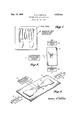
- FIGURE 1 is a diagrammatic view of an embodiment of a fatigue life gage useable in the present inventive method
- FIGURE 2 is a diagrammatic view illustrating the gage of FIGURE 1 being employed to measure the fatigue damage done to a loaded structure, wherein the gage is mounted directly on the loaded structure;
- FIGURE 3 is a diagrammatic view, similar to FIGURE 2, showing the gage of FIGURE 1 being employed to measure the fatigue damage done to a loaded structure, wherein the gage is mounted on a strain multiplier which is mounted on the loaded structure.
- the strain gage shown and described in the drawings comprises a grid of conductive material in the form of a foil, I mounted upon a backing of insulating material 2.
- the gage may be mounted directly on the structure 3 to be tested by means of adhesives, welds, or other structural fastening method, as shown in FIGURE 2; or, alternatively, the gage may be mounted on a suitable strain multiplier 7 which is, in turn, mounted on the structure 3, as shown in FIGURE 3.
- the structure 3 is loaded (by any suitable means, such as hydraulic jacks 4, 4), strain in the surface of the structure is transmitted to the conductive grid 1. Repeated straining of the grid material will permanently change the electrical resistance and/or temperature coefiicient of resistance of the grid material.
- the change in resistance or temperature coefficient of resistance of the grid material may be easily calculated from data obtained by measuring the resistance or the change in resistance of the grid under conditions of known strain and temperature levels after the test structure has been subjected to repeated loading. These resistance or temperature coefficient measurements may be made by any suitable conventional device, such as a resistance measuring circuit 5 connected to the ends of grid 1 by leads 6, 6.
- the permanent change in resistance or temperature coefficient with fatigue of the grid 1 is a function of the grid material, grid configuration and physical dimensions, heat-treat, cold-work and residual stress in the grid material, changes in these parameters may be made as required to produce the required characteristics of the fatigue gage.
- the grid has been shown here as a foil, it may be of any conductive material in the form of a film or wire, for example: constantan, Nichrome, Karma, isoelastic, or any other material used as a resistive element; aluminum, steel, stainless steel, magnesium, titanium, or any other structural material.
- Tests have been conducted on fatigue life gages of soft constantan foil, backed and faced by Bakelite impregnated glass paper with ribbon leads, about 0.25 x 0.60 x 0.006 inch, with a nominal resistance of 500 ohms and nominal gage factor (as a strain gage) of 2.06.
- the gages tested had a thermal output coefficient (temperature coefficient of resistance expressed as apparent strain degree F.) of about -3 micro-strain per degree F. before testing and were installed on 2024-T351 aluminum specimens with EPY epoxy cement under a pressure of 90 p.s.i. with a maximum curing temperature of F.
- the specimens were tension-tension fatigue tested at maximum stress levels of 40,000, 35,000, and 30,000 p.s.i.
- the tests showed that the slopes of the curves (not shown) of resistance change vs. the logarithm of the number of cycles are constant above 10,000 cycles.
- the thermal output coefficients of the gages changed during testing from about 3 microstrain per degree F. to about 10 microstrain per degree F.
- this invention provides a fatigue life gage which (1) can be applied to a local area of the test structure, (2) can measure the fatigue damage at the surface of the structure, therefore is useful in predicting the remaining fatigue life .of the structure. Its response is not influenced by irrelevant characteristics of the structure, for example, discontinuities on the surface opposite the point of application, (3) can be made in various shapes and size to satisfy particular requirements, (4) is non-destructive, (5) the out-put can be made to be affected by random loading to the same extent as the structure, eliminating the requirement for knowing a theoretical relationship between the effects of random verses constant level loading, and (6) may be installed on a strain multiplier or basic structure at.
- the method of measuring the cumulative fatigue damage at an area on a structure which is subjected to repeated loading comprising the steps of mounting a grid of conductive material on the structure to be tested so that strains in the test structure are transmitted to the grid, subjecting the structure to repeated loading which causes a permanent and finite change in the electrical resistance of the grid, measuring the change in the resistance of the grid, and determining the fatigue life of the structure by comparing the change in resistance with fatigue life data on the grid material obtained under known conditions.
- the method of determining the fatigue life of a structure under repeated loading comprising the steps of fastening a grid of electrical conductive material to a structure to be tested so that strains in the test structure are transmitted to the grid, subjecting the structure to repeated loading which causes permanent and finite changes in the temperature coeflicient of resistance of the grid, measuring the change in the temperature coefficient of resistance of the grid, and determining the fatigue life of the structure by data obtained on the fatigue life of the grid material under conditions of known strain and temperature levels.
- the method defined in claim 1 including the step of changing the rate of change of resistivity of the grid by attaching the grid to a strain-multiplier, and attaching the strain-multiplier to the structure.
- the method defined in claim 2 including the step of changing the rate of change of temperature coeflicient of the grid by attaching the grid to a strain-multiplier, and attaching the strain-multiplier to the structure.
Description
sept. 13, HARTING FATIGUE LIFE GAGING METHODS Filed Jan. 27, 1964 1 FOIL 6M0 j,
Z BAUK/N AND m/s'z/m TING MA 72 E044 g HYDRAULIC 4 JACK United States Patent 3,272,003 FATIGUE LIFE GAGING METHODS Darrell R. Harting, Seattle, Wash., assignor to The Boeing Company, Seattle, Wash, a corporation of Delaware Filed Jan. 27, 1964, Ser. No. 340,331 6 Claims. (Cl. 73-91) This invention relates generally to materials testing and more particularly to a method for measuring the cumulative fatigue damage or remaining fatigue life in a structure which is subjected to repeated loading.
Previous attempts to measure remaining fatigue life have been made utilizing ultrasonic devices, and investigating physical changes in the material of which the structure is composed. These prior methods have failed because they are either difficult to apply toa localized area or surface of the structure, or, in the latter case, because the test is destructive, and because the relationships between the results obtained and the desired fatigue life information are obscure and subject to different interpretations.
This invention broadly consists of a fatigue life gage which may be formed of a resistance element that is fabricated to possess characteristics specifically correlated with the fatigue life of the base structure whose fatigue life is to be indicated. The gage, when placed on the base structure and subjected to the same cyclic forces acting thereon, will undergo a finite and permanent change in the resistance or temperature coefficient of the gage. The change in resistance or temperature coefiicient will be directly related to the change in fatigue life remaining in the gage and in the base structure, so that at any time an indication of remaining fatigue life in the base structure may be obtained by measuring the resistance of the gage element.
Therefore, it is an object of this invention to provide a method for measuring the remaining fatigue life in an associated structure.
A further object of this invention is to provide a method for measuring the cumulative fatigue damageof a structure subjected to repeated loading.
Another object of the invention is to provide a method for determining fatigue life at the surface of the associated structure.
Another object of the invention is to provide a method for determining fatigue life utilizing a grid of conductive material which is mounted on the structure to be tested by means of adhesives, welds, or other structural fastening method.
Another object of the invention is to provide a method for determining fatigue life utilizing a grid of conductive material in the form of a foil, film or wire mounted on a structure to be tested wherein the change in resistance or temperature coefficient of resistance of the grid material is utilized in determining the fatigue life of the structure.
Other objects of the invention not specifically set forth above will become readily apparent from the following description and drawing in which:
FIGURE 1 is a diagrammatic view of an embodiment of a fatigue life gage useable in the present inventive method;
FIGURE 2 is a diagrammatic view illustrating the gage of FIGURE 1 being employed to measure the fatigue damage done to a loaded structure, wherein the gage is mounted directly on the loaded structure; and
FIGURE 3 is a diagrammatic view, similar to FIGURE 2, showing the gage of FIGURE 1 being employed to measure the fatigue damage done to a loaded structure, wherein the gage is mounted on a strain multiplier which is mounted on the loaded structure.
The strain gage shown and described in the drawings comprises a grid of conductive material in the form of a foil, I mounted upon a backing of insulating material 2. The gage may be mounted directly on the structure 3 to be tested by means of adhesives, welds, or other structural fastening method, as shown in FIGURE 2; or, alternatively, the gage may be mounted on a suitable strain multiplier 7 which is, in turn, mounted on the structure 3, as shown in FIGURE 3. When the structure 3 is loaded (by any suitable means, such as hydraulic jacks 4, 4), strain in the surface of the structure is transmitted to the conductive grid 1. Repeated straining of the grid material will permanently change the electrical resistance and/or temperature coefiicient of resistance of the grid material. The change in resistance or temperature coefficient of resistance of the grid material may be easily calculated from data obtained by measuring the resistance or the change in resistance of the grid under conditions of known strain and temperature levels after the test structure has been subjected to repeated loading. These resistance or temperature coefficient measurements may be made by any suitable conventional device, such as a resistance measuring circuit 5 connected to the ends of grid 1 by leads 6, 6.
Because the permanent change in resistance or temperature coefficient with fatigue of the grid 1 is a function of the grid material, grid configuration and physical dimensions, heat-treat, cold-work and residual stress in the grid material, changes in these parameters may be made as required to produce the required characteristics of the fatigue gage.
While the grid has been shown here as a foil, it may be of any conductive material in the form of a film or wire, for example: constantan, Nichrome, Karma, isoelastic, or any other material used as a resistive element; aluminum, steel, stainless steel, magnesium, titanium, or any other structural material.
Tests have been conducted on fatigue life gages of soft constantan foil, backed and faced by Bakelite impregnated glass paper with ribbon leads, about 0.25 x 0.60 x 0.006 inch, with a nominal resistance of 500 ohms and nominal gage factor (as a strain gage) of 2.06. The gages tested had a thermal output coefficient (temperature coefficient of resistance expressed as apparent strain degree F.) of about -3 micro-strain per degree F. before testing and were installed on 2024-T351 aluminum specimens with EPY epoxy cement under a pressure of 90 p.s.i. with a maximum curing temperature of F. The specimens were tension-tension fatigue tested at maximum stress levels of 40,000, 35,000, and 30,000 p.s.i. (4,000, 3,500, and 3,000 micro-strain) with a ratio (R) of minimum to maximum stress of +02. and tensioncompression fatigue tested at a maximum of 36,700 p.s.i. tension, minimum of 10,700 p.s.i. compression +3,6 70 to 1,070 microstrain, R=.29). The tests were run at room temperature with constant amplitude cyclic loading.
The tests showed that the slopes of the curves (not shown) of resistance change vs. the logarithm of the number of cycles are constant above 10,000 cycles. The slopes (not shown) in ohms per decade of applied load cycles resulting from the tension-tension tests (R=+.0=2) are proportional to the difference between the maximum stress level applied and a constant (25,000 p.s.i.). The thermal output coefficients of the gages changed during testing from about 3 microstrain per degree F. to about 10 microstrain per degree F.
When the test curves (not shown) of resistance change vs. the logarithm of the number of cycles are extrapolated to the numbers of cycles required to fail 2024 aluminum as indicated by S-N curves, it is apparent that for a ratio of maximum to minimum stress of +02 the fatigue gage would have changed resistance by about 22 ohms (with a tolerance of less than 10% If this relationship were to hold for all stress ratios, the gage should integrate fatigue damage under random loading if it is assumed that fatigue damage varies (before failure) with cycling in the same manner as resistance change.
It has thus been shown that the remaining fatigue life in aluminum can be determined by the fatigue life gage of the invention when utilizing a grid of constantan foil, thereby indicating that it is not always necessary to utilize a grid of the same material as the material being tested.
The tests conducted on aluminum using a gage of constantan foil clearly indicated that (1) the permanent resistance change resulting from fatigue loading at a constant amplitude of alternating strain is a function of the number of applied cycles, (2) that this resistance change is large enough to be easily measured, (3) that the rate of change of resistance with cycling is a. function of the maximum strain level and the ratio of minimum to maximum strain, and (4) the gages subjected to the same loading pattern would change resistance by the same amount within a reasonable tolerance for fatigue work (l15 percent).
It has thus been shown that this invention provides a fatigue life gage which (1) can be applied to a local area of the test structure, (2) can measure the fatigue damage at the surface of the structure, therefore is useful in predicting the remaining fatigue life .of the structure. Its response is not influenced by irrelevant characteristics of the structure, for example, discontinuities on the surface opposite the point of application, (3) can be made in various shapes and size to satisfy particular requirements, (4) is non-destructive, (5) the out-put can be made to be affected by random loading to the same extent as the structure, eliminating the requirement for knowing a theoretical relationship between the effects of random verses constant level loading, and (6) may be installed on a strain multiplier or basic structure at. a location other than that at which fatigue damage measurements are required, fatigue damage at the required location being determined from gage measurements if the relationship between stress or strain levels at the fatigue gage location and the desired location are known. Although a particular embodiment of the invention has been illustrated and described, it will be obvious to those skilled in the art that various changes and modifications may be made without departing from the invention, and it is intended'to cover in the appended claims all such changes and modifications that come within the true spirit and scope of the invention.
What I claim is:
1. The method of measuring the cumulative fatigue damage at an area on a structure which is subjected to repeated loading comprising the steps of mounting a grid of conductive material on the structure to be tested so that strains in the test structure are transmitted to the grid, subjecting the structure to repeated loading which causes a permanent and finite change in the electrical resistance of the grid, measuring the change in the resistance of the grid, and determining the fatigue life of the structure by comparing the change in resistance with fatigue life data on the grid material obtained under known conditions.
2. The method of determining the fatigue life of a structure under repeated loading comprising the steps of fastening a grid of electrical conductive material to a structure to be tested so that strains in the test structure are transmitted to the grid, subjecting the structure to repeated loading which causes permanent and finite changes in the temperature coeflicient of resistance of the grid, measuring the change in the temperature coefficient of resistance of the grid, and determining the fatigue life of the structure by data obtained on the fatigue life of the grid material under conditions of known strain and temperature levels.
3. The method defined in claim 1 including the step of changing the rate of change of resistivity of the grid by attaching the grid to the structure under a condition of known pre-strain.
4. The method defined in claim 1 including the step of changing the rate of change of resistivity of the grid by attaching the grid to a strain-multiplier, and attaching the strain-multiplier to the structure.
5. The method defined in claim 2 including the step of changing the rate of change of temperature coefficient of the grid by attaching the grid to the structure under a condition of known pre-strain.
6. The method defined in claim 2 including the step of changing the rate of change of temperature coeflicient of the grid by attaching the grid to a strain-multiplier, and attaching the strain-multiplier to the structure.
References Cited by the Examiner UNITED STATES PATENTS 2,449,883 9/1948 De Forest 7388.5 X 2,553,986 5/1951 Statham 324 X 2,920,480 1/1960 Haas 7388 3,060,728 10/1962 Wolber 7386 FOREIGN PATENTS 150,281 1962 Russia.
RICHARD C. QUEISSER, Primary Examiner.
CHARLES A. RUEHL, Assistant Examiner.
Claims (1)
1. THE METHOD OF MEASURING THE CUMULATIVE FATIGUE DAMAGE AT AN AREA ON A STRUCTURE WHICH IS SUBJECTED TO REPEATED LOADING COMPRISING THE STEPS OF MOUNTING A GRID OF CONDUCTIVE MATERIAL ON THE STRUCTURE TO BE TESTED SO THAT STRAINS IN THE TEST STRUCTURE ARE TRANSMITTED TO THE GRID, SUBJECTING THE STRUCTURE TO REPEATED LOADING WHICH CAUSES A PERMANENT AND FINITE CHANGE IN THE ELECTRICAL RESISTANCE OF THE GRID, MEASURING THE CHANGE IN THE RESISTANCE OF THE GRID, AND DETERMINING THE FATIGUE LIFE OF THE STRUCTURE BY COMPARING THE CHANGE IN RESISTANCE WITH FATIGUE LIFE DATA ON THE GRID MATERIAL OBTAINED UNDER KNOWN CONDITIONS.
Priority Applications (1)
| Application Number | Priority Date | Filing Date | Title |
|---|---|---|---|
| US340331A US3272003A (en) | 1964-01-27 | 1964-01-27 | Fatigue life gaging methods |
Applications Claiming Priority (1)
| Application Number | Priority Date | Filing Date | Title |
|---|---|---|---|
| US340331A US3272003A (en) | 1964-01-27 | 1964-01-27 | Fatigue life gaging methods |
Publications (1)
| Publication Number | Publication Date |
|---|---|
| US3272003A true US3272003A (en) | 1966-09-13 |
Family
ID=23332894
Family Applications (1)
| Application Number | Title | Priority Date | Filing Date |
|---|---|---|---|
| US340331A Expired - Lifetime US3272003A (en) | 1964-01-27 | 1964-01-27 | Fatigue life gaging methods |
Country Status (1)
| Country | Link |
|---|---|
| US (1) | US3272003A (en) |
Cited By (19)
| Publication number | Priority date | Publication date | Assignee | Title |
|---|---|---|---|---|
| US3602041A (en) * | 1969-05-28 | 1971-08-31 | Us Army | Engine wear life measurement |
| US3763701A (en) * | 1971-07-05 | 1973-10-09 | G Wright | Web tension devices |
| US3782182A (en) * | 1971-04-29 | 1974-01-01 | Vishay Intertechnology Inc | Strain multiplier |
| US3782178A (en) * | 1970-07-31 | 1974-01-01 | Hawker Siddeley Aviation Ltd | Fatigue sensors |
| US3828606A (en) * | 1972-12-06 | 1974-08-13 | Boeing Co | Method for determining thermal fatigue of electronic components |
| US4175446A (en) * | 1978-04-26 | 1979-11-27 | The University Of Iowa Research Foundation | Step counting device and method |
| US4255049A (en) * | 1977-11-08 | 1981-03-10 | Dornier System Gmbh | Non-destructive testing of structural elements for fatigue by measurement of specular reflectance |
| USRE31312E (en) * | 1977-10-11 | 1983-07-19 | W. J. Industries, Inc. | Tension monitor means |
| US5355734A (en) * | 1990-06-12 | 1994-10-18 | Kabushiki Kaisha Komatsu Seisakusho | Life predicting gauge for structure and life predicting method employing the same |
| US5528151A (en) * | 1992-11-09 | 1996-06-18 | Hughes Aircraft Company | Thermal fatigue testing using plural test trips with graduated sizing and recessed anchoring |
| US5598101A (en) * | 1991-12-18 | 1997-01-28 | U.S. Philips Corporation | Circuit arrangement having a wear indicator to indicate end of service life |
| US20020059835A1 (en) * | 2000-10-27 | 2002-05-23 | Yazaki Corporation | Fixing structure for sensing element |
| US6810753B2 (en) * | 2000-08-29 | 2004-11-02 | The Cleveland Clinic Foundation | Displacement transducer |
| US20040216530A1 (en) * | 2003-04-29 | 2004-11-04 | Kwon Young Wuk | Fatigue measurement device and method |
| US20110255813A1 (en) * | 2008-12-22 | 2011-10-20 | Aktiebolaget Skf | Sensorized Bearing Unit |
| WO2011098079A3 (en) * | 2010-02-12 | 2011-10-27 | Fraunhofer-Gesellschaft zur Förderung der angewandten Forschung e.V. | Sensing system for determining the fatigue on metal components |
| US20130305833A1 (en) * | 2012-05-17 | 2013-11-21 | Department Of The Navy, Office Of Counsel - Nawcad | Method for Measuring Fatigue |
| DE102018008724A1 (en) * | 2018-11-07 | 2020-05-07 | Klaus Faber AG | Measuring method for determining a structural and wear condition of a component and use of a measurement in the surface area of a metallic electrical conductor |
| US11592377B2 (en) | 2020-04-20 | 2023-02-28 | Vishay Measurements Group, Inc. | Fatigue life sensor for measuring repetitive loads applied to a structure based upon cracks propagating from crack initiation features of the sensor |
Citations (4)
| Publication number | Priority date | Publication date | Assignee | Title |
|---|---|---|---|---|
| US2449883A (en) * | 1945-01-08 | 1948-09-21 | Baldwin Locomotive Works | Fatigue indicator |
| US2553986A (en) * | 1947-07-14 | 1951-05-22 | Statham Lab Inc | Method and apparatus for testing the bonding of bonded strain gauges |
| US2920480A (en) * | 1956-01-18 | 1960-01-12 | Haas Tibor | Methods for indicating the expiration of the assigned or safe life of structural members |
| US3060728A (en) * | 1959-06-22 | 1962-10-30 | Pure Oil Co | Method and apparatus for measuring corrosion of stressed materials |
-
1964
- 1964-01-27 US US340331A patent/US3272003A/en not_active Expired - Lifetime
Patent Citations (4)
| Publication number | Priority date | Publication date | Assignee | Title |
|---|---|---|---|---|
| US2449883A (en) * | 1945-01-08 | 1948-09-21 | Baldwin Locomotive Works | Fatigue indicator |
| US2553986A (en) * | 1947-07-14 | 1951-05-22 | Statham Lab Inc | Method and apparatus for testing the bonding of bonded strain gauges |
| US2920480A (en) * | 1956-01-18 | 1960-01-12 | Haas Tibor | Methods for indicating the expiration of the assigned or safe life of structural members |
| US3060728A (en) * | 1959-06-22 | 1962-10-30 | Pure Oil Co | Method and apparatus for measuring corrosion of stressed materials |
Cited By (23)
| Publication number | Priority date | Publication date | Assignee | Title |
|---|---|---|---|---|
| US3602041A (en) * | 1969-05-28 | 1971-08-31 | Us Army | Engine wear life measurement |
| US3782178A (en) * | 1970-07-31 | 1974-01-01 | Hawker Siddeley Aviation Ltd | Fatigue sensors |
| US3782182A (en) * | 1971-04-29 | 1974-01-01 | Vishay Intertechnology Inc | Strain multiplier |
| US3763701A (en) * | 1971-07-05 | 1973-10-09 | G Wright | Web tension devices |
| US3828606A (en) * | 1972-12-06 | 1974-08-13 | Boeing Co | Method for determining thermal fatigue of electronic components |
| USRE31312E (en) * | 1977-10-11 | 1983-07-19 | W. J. Industries, Inc. | Tension monitor means |
| US4255049A (en) * | 1977-11-08 | 1981-03-10 | Dornier System Gmbh | Non-destructive testing of structural elements for fatigue by measurement of specular reflectance |
| US4175446A (en) * | 1978-04-26 | 1979-11-27 | The University Of Iowa Research Foundation | Step counting device and method |
| US5355734A (en) * | 1990-06-12 | 1994-10-18 | Kabushiki Kaisha Komatsu Seisakusho | Life predicting gauge for structure and life predicting method employing the same |
| US5598101A (en) * | 1991-12-18 | 1997-01-28 | U.S. Philips Corporation | Circuit arrangement having a wear indicator to indicate end of service life |
| US5528151A (en) * | 1992-11-09 | 1996-06-18 | Hughes Aircraft Company | Thermal fatigue testing using plural test trips with graduated sizing and recessed anchoring |
| US6810753B2 (en) * | 2000-08-29 | 2004-11-02 | The Cleveland Clinic Foundation | Displacement transducer |
| EP1202032B1 (en) * | 2000-10-27 | 2007-02-28 | Yazaki Corporation | Fixing structure for sensing element |
| US20020059835A1 (en) * | 2000-10-27 | 2002-05-23 | Yazaki Corporation | Fixing structure for sensing element |
| US6983665B2 (en) * | 2000-10-27 | 2006-01-10 | Yazaki Corporation | Fixing structure for sensing element |
| US20040216530A1 (en) * | 2003-04-29 | 2004-11-04 | Kwon Young Wuk | Fatigue measurement device and method |
| US6983660B2 (en) | 2003-04-29 | 2006-01-10 | Young Wuk Kwon | Fatigue measurement device and method |
| US20110255813A1 (en) * | 2008-12-22 | 2011-10-20 | Aktiebolaget Skf | Sensorized Bearing Unit |
| WO2011098079A3 (en) * | 2010-02-12 | 2011-10-27 | Fraunhofer-Gesellschaft zur Förderung der angewandten Forschung e.V. | Sensing system for determining the fatigue on metal components |
| US20130305833A1 (en) * | 2012-05-17 | 2013-11-21 | Department Of The Navy, Office Of Counsel - Nawcad | Method for Measuring Fatigue |
| US8707795B2 (en) * | 2012-05-17 | 2014-04-29 | The United States Of America As Represented By The Secretary Of The Navy | Method for measuring fatigue |
| DE102018008724A1 (en) * | 2018-11-07 | 2020-05-07 | Klaus Faber AG | Measuring method for determining a structural and wear condition of a component and use of a measurement in the surface area of a metallic electrical conductor |
| US11592377B2 (en) | 2020-04-20 | 2023-02-28 | Vishay Measurements Group, Inc. | Fatigue life sensor for measuring repetitive loads applied to a structure based upon cracks propagating from crack initiation features of the sensor |
Similar Documents
| Publication | Publication Date | Title |
|---|---|---|
| US3272003A (en) | Fatigue life gaging methods | |
| US3979949A (en) | Fatigue damage indicator | |
| US2363181A (en) | Strain gauge | |
| US3184962A (en) | Strain type transducers | |
| US2467752A (en) | Wrapped wire strain gauge | |
| Lam et al. | The effect of residual stress and its redistribution of fatigue crack growth | |
| US2356763A (en) | Method and means for testing materials | |
| US3278881A (en) | Membrane strain gauge | |
| JPH01132902A (en) | Strain gauge with compensatable creep and method of obtaining the same | |
| US6134971A (en) | Stress induced voltage fluctuation for measuring stress and strain in materials | |
| US3914991A (en) | Strain gage mounting assembly | |
| US3738162A (en) | Fatigue damage indicator | |
| US3602041A (en) | Engine wear life measurement | |
| Wu | Transverse sensitivity of bonded strain gages: A method for determining the transverse-sensitivity values of strain gages, using a special test apparatus, is described by the author | |
| US2553986A (en) | Method and apparatus for testing the bonding of bonded strain gauges | |
| US3433060A (en) | Strain gage transducer assembly | |
| US3252321A (en) | Piezoresistive material | |
| US4442718A (en) | Strain gauge and electric circuit for adjustment and calibration of same | |
| US3314034A (en) | Semiconductor strain gage system | |
| Kaufman | Investigation of strain gages for use at cryogenic temperatures: Paper reports the results of an investigation undertaken to study the performance characteristics of a number of commercially available strain gages from room temperature to 36° R and for resistance measurements to 7° R | |
| US2486625A (en) | Electric strain measuring device | |
| US3498118A (en) | Self-heating compensation for bonded filament strain gage transducers | |
| Gowda et al. | Performance of miniature resistance strain gages in low-cycle fatigue: Paper reports investigation of the performance characteristics of miniature resistance strain gages subjected to cyclic strains of high amplitude | |
| US3884080A (en) | Vacuum gage | |
| US3324706A (en) | Apparatus for temperature compensation of strain gages |
Legal Events
| Date | Code | Title | Description |
|---|---|---|---|
| AS | Assignment |
Owner name: MANUFACTURERS NATIONAL BANK OF DETROIT, A NATIONAL Free format text: SECURITY INTEREST;ASSIGNOR:MEASUREMENT GROUP, INC. A CORP. OF DE.;REEL/FRAME:004568/0641 Effective date: 19860514 |
|
| AS | Assignment |
Owner name: MANUFACTURERS BANK, N.A. - F/K/A MANUFACTURERS NA Free format text: TO AMEND THE TERMS AND OBLIGATIONS OF A SECURITY AGREEMENT DATED 7-31-90.;ASSIGNOR:MEASUREMENTS GROUP, INC., A DE CORP.;REEL/FRAME:006021/0173 Effective date: 19920110 |