US3290597A - Emergency assistance radio signaling system - Google Patents
Emergency assistance radio signaling system Download PDFInfo
- Publication number
- US3290597A US3290597A US517168A US51716865A US3290597A US 3290597 A US3290597 A US 3290597A US 517168 A US517168 A US 517168A US 51716865 A US51716865 A US 51716865A US 3290597 A US3290597 A US 3290597A
- Authority
- US
- United States
- Prior art keywords
- transmitter
- radio
- signal
- frequency
- emergency
- Prior art date
- Legal status (The legal status is an assumption and is not a legal conclusion. Google has not performed a legal analysis and makes no representation as to the accuracy of the status listed.)
- Expired - Lifetime
Links
Images


Classifications
-
- G—PHYSICS
- G08—SIGNALLING
- G08B—SIGNALLING OR CALLING SYSTEMS; ORDER TELEGRAPHS; ALARM SYSTEMS
- G08B25/00—Alarm systems in which the location of the alarm condition is signalled to a central station, e.g. fire or police telegraphic systems
- G08B25/01—Alarm systems in which the location of the alarm condition is signalled to a central station, e.g. fire or police telegraphic systems characterised by the transmission medium
- G08B25/012—Alarm systems in which the location of the alarm condition is signalled to a central station, e.g. fire or police telegraphic systems characterised by the transmission medium using recorded signals, e.g. speech
Definitions
- the presen-t invention relates generally to an emergency radio signalin-g system for use by individuals, such as law enforcement oflicers, in need of assistance to communicate an emergency signal to ⁇ a central station; more particularly, the invention relates to an emergency radio signaling system for use by such individuals, wherein a triggering signal is initia-ted by portable transmitter means on an individual to initiate transmission of :a predetermined output by equipment on the individuals mobile unit in his vicinity to a central station.
- the embodimen-ts of the invention herein shown and described relate to emergency radio signaling systems adapted for use by law enforce-ment officers in cooperation with radio equipment mounted in their mobile units or patrol cars and at a central station, such as a police headquarters.
- Preferred embodiments of the syste-m each include a portable transmitter adapted to be carried by an individual, radio 'receiving and transmitting equipment in the individuals mobile unit or patrol car, control means connected With the receiving and transmitting equipment for switching the equipment from receive to transmit in response to a triggering signal from the portable transmitter, means responsive -t-o this control means to produce a predetermined radio signal or audio output for transmission by the transmitting equipment, and central sta-tion radio equipment for receiving this transmission.
- the system I thus provides for the identiiication of the particular individual summoning assist- :ance by his portable transmitter.
- the predetermined output transmitted by the transmitting equipment is provided by a speech recorder, and the output comprises a pre-recorded message.
- the transmitted message is received by the radio equipment at the central station and provides identifica-tion of the individual who is summoning assistance, las Well as other needed information.
- the predetermined output transmitted from the mobile unit transmitting equip-ment comprises ⁇ a characteristic emergency signal provided by an oscillator which is responsive to the control means. This signal, Iwhich is characteristic of the particular transmitting equipment, is received by equipment and the central station, which equipment dis'- criminates and identifies the characteristic signal.
- the individual switches on his portable transmitter, which is adapted to be readily switched on by movement of a portion of his body or manually, thereby generating a triggering signal.
- the control unit in the ice patrol car automatically switches the transmitting and receiving equipment to transmitting operation by means of activating replays, and enengizes means which produce the predetermined output for transmission.
- this output may preferably be a pre-recorded voice message provided by a speech recorder. It may be a characteristic emergency signal provided by an oscillator responsive to the control means. In systems utilizing a pre-recorded message, no special equipment is required at the central station to identify individual summoning assistance.
- the central sta-tion equipment includes contr-ol equipment inclu-ding a plurality of tuned circuits which are responsive to respective characteristic emergency signals from respective patrol cars, one of which tuned circuits is lresponsive to the characteristic signal from the particular patrol car of the individual 1who -operated the portable transmitter.
- the tuned circuit actuates a tuned relay, or equivalent tuned switching means, which then enengizes a lamp or other signal means, as on a control panel, which identifies the individual who signalled for emergency assistance.
- any of a number of law enforcement oflicers may readily initiate a triggering signal by means of his portable transmitter, thereby causing the transmission from his mobile unit or patrol car of an identifiable transmission to the central station, thereby identifying the particular individual or patrol car in need of assistance.
- An object of the invention is the provision of an emergency radio signaling system for use by an individual, such as a law enforcement officer, to communicate for assistance from his person through mobile equipment in his vicinity to a central station.
- An object of the present invention is the provision of an emergency radio signaling system in accordance with the foregoing objects, wherein speech recorder means reproduce a pre-recorded emergency message for transmission by the mobile equipment to the central station.
- An object of the invention is the provision of an emergency assistance radio signaling system in accordance with certain of the foregoing objects, for use by persons in circumstances of distress, wherein any one of respective transmitters carried by respective individuals triggers equipment on an individuals mobile ⁇ unit in his vicinity, thereby transmitting la respective characteristic emergency signal to a central station provided with equipment which monitors and discri-minates to identify the individual in distress.
- An object of this invention is to provide an emergency assistance radio signaling system according to the foregoing objects, wherein the system is readily integrated with conventional law enforcement communications equipment by the integration of control components in units which are readily connectable with conventional communicationsl equipment used in mobile units and central stations, such as the equipment of law enforcement organizations.
- An object of the invention is the provision of an emergency assistance radio signaling system in accordance with the foregoing objects, wherein a portable transmitter car-y ried by an individual for use in the system is adapted to be readily switched on for transmission manually or by movement of a portion of the individuals body.
- FIGURE 1 is a diagrammatic perspective view illustrating generally the application and utility of a preferred embodiment of the present invention
- FIGURE 2 is a block diagram of a preferred embodiment of the system of the invention, wherein features of its operation are indicated;
- FIGURE 3 is a schematic diagram showing the electrical circuitry of an exemplary form of portable personal transmitter utilized with the invention
- FIGURE 4 is a block diagram showing a preferred manner of assembling or integrating the system of the invention with conventional equipment
- FIGURE 5 is a block diagram illustrating an embodiment of the system of the invention.
- FIGURE 6 is a block diagram illustrating an embodiment of the system of the invention.
- FIGURE 7 is a block diagram of the system of the invention incorporating specific details of a form of the invention involving a system similar to that shown in FIG- URE 5;
- FIGURE 8 is a partially schematic and partially block circuit diagram of the decoder portion of FIGURE 7;
- FIGURE 9 is a detailed schematic circuit diagram of a frequency sensitive network which may be employed in the decoder of FIGURE 8.
- FIGURE 10 is a schematic circuit diagram of another form of oscillator and transmitter circuit for generating the coded signal transmission as indicated in FIGURE 7 and related to the transmitter shown in FIGURE 3.
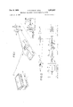
- FIGURE 1 illustrates the utilization of a preferred embodiment of the invention.
- a law enforcement oicer 10 being menaced by an armed criminal, is outside and at a distance from his vehicle or patrol car 12, and therefore cannot directly operate the radio'equipment in the vehicle to summon assistance by communicating with a central station or police headquarters 14.
- the officer switches on a portable transmitter 16, which is provided with a switch 40 as shown in FIGURES 3 and 10, which is readily operable, as by a particular movement of a portion of the oflicers body or which is manually operable.
- the portable transmitter 16 broadcasts a triggering signal t-o the radio equipment mounted in the vehicle 12, which equipment thereupon transmits a predetermined emergency message or signal to the central station 14, as hereinafter described in detail,
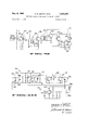
- FIGURE 2 illustrates diagrammatically the components and certain operating characteristics of the preferred form of the emergency signaling system.
- the small battery-powered portable transmitter 16 which is carried on the person of an individual, has a transmitting antenna 18 (or 18a as shown in FIGURE 10) and transmits a carrier frequency Fc which is modulated with an audio frequency F1.
- the radio equipment in the vehicle 12 includes a receiver 20 which is tuned to the same frequency as portable transmitter 16, and which is connected with a speaker 22.
- Control equipment of the invention includes a tuned circuit such Vas shown in FIGURE 9 connected to the output yof receiver 20, which circuit, in -response to the incoming triggering Isignal from the portable transmitter, switches the receiving and transmitting equipment or transceiver in the vehicle from receiving operation to transmitting operation, activating the transmitter 24. Simultaneously, the tuned circuit energizes a s'peech recorder .26, as described in further detail below and shown particularly in FIGURE 9, the output of which is fed into transmitter 24.
- This output is a pre-recorded voice message, which may either be a coded or identifying message recorded at an earlier time, or a particular message giving the particular individuals emergency circumstances, in the manner hereinafter discussed.
- the receiver 20 demodulates the carrier frequency Fc of the emergency signal from the portable transmitter, and the demodulated signal F1 is gated through the amplifier of the receiver to a tuned relay 28, which may be a tuned circuit or a transistorized switching element, which circuit is a part of the control equipment.
- the transmitter 24 broadcasts by means of its antenna 30 the prerecorded message to the central station 14 (FIGURE l).
- a tuned amplifier circuit resonant at the frequency of the demodulated signal may be used.
- the equipment at the headquarters or central station 14 includes receiving equipment 32 which is provided with a receiving antenna 34 and 'which is connected to output means, such asa speaker 36.
- FIGURE 3 schematically illustrates the circuitry of a preferred form of the portable transmitter 16 which is utilized in accordance with the invention.
- the transmitter is of such a size and configuration that it is conveniently carried on the person of the user, and its operation is initiated in a convenient and ready manner, either manually or by movement or expansion of a portion of the body of the user, as by mechanical switch means 40 shown in FIGURE 3.
- the transmitter is powered -by a battery 38, and is activated by switch 40.
- a free running multivibrator or oscillator is provided by the circuitry which includes the transistors 42, 44, the associated resistors 46, 48, 50, 52 land the capacitors 54, 56, which Ioscillator operates in the audio frequency range.
- a Colpitts oscillator which operates -in the radio frequency range, is provided by the connection of transistor 58, resistors 60, 62, 64, the crystal 66, the capacitors 68, 70, and the inductance 72. It will be understood that the audio frequency oscillator and the radio frequency .oscillator thus provided are well known to those versed in the art.
- the multivibrator audio frequency oscillator is coupled to the radio frequency oscillator through resistor 74 and capacitor 76.
- the radio frequency oscillator is therefore modulated by the audio frequency oscillator.
- the modulated .output of the radio frequency oscillator 4 is coupled to the antenna 18 of the portable transmitter from a tap on the Kinductor 72, which is a part lof a parallel tuned collector tank circuit which includes the capacitor 68.
- FIGURE 10 another form of transmitter 16 is shown at 16a in which a crystal-controlled oscillator transistor is employed and in which a novel means of frequencymodulating the oscillator is shown and can be described as follows: From base 101 of transistor oscillator 100 a quartz crystal unit 102 is connected to the parallel combination of a variable capacitor 103 and a diode device 104. The other junction of the parallel combination is connected to ground at 105. Diode 104 is Iof a type which acts as a capacitor. The capacitance of the capacitor/diode 104 can be varied Iby a voltage applied there to.
- multiplier and output circuit block 110 wherein in simplified schematic form the output circuits of transmitter 16 are shown.
- the final amplifier/multiplier tank circuit 18a is the antenna of the embodiment of the transmiter 16a shown in FIGURE 1-0.
- Transistor 120 is connected in a phase shift audio oscillator configuration of known design.
- a resistor 121 is coupled between -collector 122 of transistor 120 and junction 106 of diode 104, capacitor 103 and crystal 102.
- the collector lo-ad resistor 123 of transistor 120 can be seen to be in parallel with the ser-ies combination of resistor 121 and diode/ capacitor 104 so that any Variation in the voltage across resistor 123 will produce a proportional volta'ge variation at junction 106 with respect to ground at 105.
- the deviation in frequency of oscillator 100 will be multiplied by the overall multiplication factor achieved with multiplier chain 110 and the tripled output of tuned circuit 107.
- phase shift oscillator output signal appearing across resistor 123 will frequency modulate transmitter oscillator 100 and produce a corresponding frequency modulated output of relatively wide deviation at antenna 18a each tune switch 40a is operated (closed) as herein'bef-ore described.
- a preferred arrangement of components and equipment according to the invention in relation to conventional vehicle radio equipment and central station equipment is illustrated Iin FIGURE 4.
- the overall radio equipment in the mobile unit or patrol car is indicated at 76.
- a control unit 78 preferably embodied in a unitary housing, -inoorporates the speech recorder 26 and the tuned relay 28.
- the unit 78 is connected with the transmitter 24 .and the receiver 20 by means of an electrical connector or cable 80, and is connected to the speaker 22 by an electrical connector, which is preferably a part of the cable.
- the integration of these components into the control unit facilitates the convenient coupling and integration of components of the system of the invention with conventional radio equipment of the vehicles and central stations of law enforcement organizations.
- the tuned relay receives and discriminates the incoming triggering signal from the portable transmitter 16 and operates the switching element for switching the radio equipment in the vehicle from receive to transmit
- the tuned relay also energizes the speech recorder to effect transmission of the pre-recorded emergency voice message.
- transmitter 16a on the person frequency Imodulated transmitter of a coded signal.
- this transmitter (shown in more detail in FIGURE 10) can generate an output at about 12 times the normal crystal frequency. This is achieved by the tripler action of circuit 108 in FIGURE l0 and doubling in each of the tuned circuits 109 and 18a in multiplier 110. Thus a crystal frequency of 12.5 mc. would produce an output at 150 mc.
- This signal is frequency modulated at the frequency of phase shift oscillator 120.
- the equipment in a patrol car 12a shown in FIGURE 7 includes a receiver 130 ⁇ responsive to transmitter 16a to demodulate the frequency modulated signal and recover a signal corresponding to the frequency of phase shift oscillator 120.
- a receiver 130 ⁇ responsive to transmitter 16a to demodulate the frequency modulated signal and recover a signal corresponding to the frequency of phase shift oscillator 120.
- Such ydemodulating equipment is well known in the art.
- the demodulated signal is applied to a decoder 131 (further shown in FIGURE 9) and the modulator 132 of the transmitter 133 is made responsive by the decoder to either the normal speech equipment therein or the 6 recorded signal from an endless loop tape cartridge as illustrated in FIGURE 8.
- the signals from transmitter 133 are received and processed as hereinbefore described.
- the circuit schematic diagram shown in FIGURE 9 corresponds to the decoder 131 shown in FIGURE 7.
- a signal from the receiver (the demonstrated signal) appears at input terminal and includes any noise plus the oscillation frequency generated by phase-shift oscillator 120.
- This signal is amplified by conventional transistor limiter-amplifier 141, the output load resistor 142 of which is a potentiometer, by which a proportion of the output of amplifier 141 may tbe selected at a-rm 143 of control 142.
- This selected output signal is applied through a limiting resistor 144 to a resonant transformer assembly 145 which selects only the signal frequency of the phase shift oscillator to which it is resonant and excludes any other signals or noise.
- This selected signal frequency is further amplified in conventional amplifier 146 and applied through output transformer 147 connected to transistor amplifier 146 to a motor and lamp driver circuit including transistors 148 aud 149, connected in a direct-coupled configuration.
- a jumpered connection 151 leads to a lamp 152 and a motor 153, the motor 153 returning to ground at 155.
- Diodes 156- 157 discharge transients across motor 153 by conducting on reverse polarity pulses which may result from the start and stop action ⁇ of motor 153.
- a switch 158 is connected across motor 153 to short it and so that test signals will only light lamp 152 and not -operate motor 153-.
- the recorded message on the tape 160 in cartridge 26 is picked up by playback head 161 and applied to a preamplifier 162 of conventional design.
- This output 163 of amplifier 162 provides an amplified counterpart of the signal (a pre-recorded message) on tape 160, across a potentiometer 164 and onto the base 165 of a transistor output amplifier 166 through resistor 167 and capacitor 168.
- the appearance of signals from output 163 at transistor 166 results in a signal on transformer 170 which in turn applies the signal to diode 171.
- Diode 171 rectifies the signal and charges capacitor 172 to produce a positive polarity signal on base 173 of transistor 174.
- Transistor 174 is directly coupled to transistor 175 through a resistor 176 so that transistor 175 4becomes conductive to apply current through relay coil 177.
- Relay contacts 178 are normally open.
- contacts 179-180 are closed to apply the signal from control 164 to the modulator (at of transmitter 133 as previously described.
- capacitor 172 discharges and transistors 174, 175 are nonconductive to release relay contacts 178 to the normally deenergized condition closing contacts 181 so that the transmitter modulator 185 may receive the normal speech audio from the two-Way radio microphone system 184.
- This message may be recorded 'at a time prior to the indication of any emergency, and may typically be such a message as Car 79-Code 3.
- An individual such as a police officer, may pre-record an emergency message immediately prior to leaving his vehicle under circumstances wherein an emergency may arise.
- a message might be: 10:42, officer John Doesaw three men lurking inside fence at warehouse at 2434 Riverside Street-leaving car to investigate.
- the individual or oiiicer can effect transmission from his portable transmitter by an appropriate body movement or manually, thereby effecting transmission from the radio equipment in his mobile unit of the prerecorded emergency message to the central headquarters. From the message, personnel at the central station or headquarters .are provided with information necessary for the dispatch of assistance.
- FIGURES 5 and 6 Iare diagrammatic illustrations of the components and operating characteristics of another embodiment of the emergency radio signaling system of the invention. As indicated in these figures, this embodiment differs from the embodiment illustrated in FIG- URES 2 and 4 in that a local oscillator 82 is substituted for the speech recorder 26 of .the other embodiment, and in that a set of tuned circuits y84 and an indicating panel 85 are provided at the central station.
- the tuned circuit switches the equipment in the vehicle to transmitting operation, and simultaneously energizes the local oscillator 82, the output of which is ⁇ fed into the transmitter 24.
- Receiver demodulates the carrier frequency Fc of the emergency signal from the portable transmitter, and the demodulated signal F1 is gated through the amplifier of the receiver to the tuned relay 28, which is a part of the control equipment of the invention.
- Transmitter 24 broadcasts to headquarters or central station 14 (FIG- URE l) an emergency signal comprising the carrier signal Fc on which is superimposed a signal F3 generated lby the local oscillator 82.
- the duration of the transmission of this emergency signal is preferably short and is preferably limited by an internal timing circuit within the control equipment.
- the set of tuned circuits 84 is electrically connected with an indicating panel 86, which is equipped With indicating means, preferably signal lamps, and which may also include such indicating means as audible signal devices.
- a particular one of the tuned circuits 84 in response to the incoming emergency signal, selectively energizes one of the indicating lamps or devices.
- the central station equipment thus discriminates and identifies the characteristic emergency signal from the particular vehicle of t-he individual who is summoning assistance by means of his portable transmitter. Personnel at the central station are thereby enabled to dispatch assistance.
- tuned relay 28 may also enl ergize a time cycling unit (not shown) which governs the time duration of the emergency sign-al broadcast from the vehicle transmitter 24.
- the tuned relay in the coding programming stage also energizes the local oscillator 82, thereby effecting transmission of .a ⁇ characteristic emergency signal from the transmitter 24, this signal serving to identify the particular transmitter land vehicle.
- An automatic emergency assistance-calling communications system comprising in combination:
- a first radio receiver adapted to be responsive to the modulated signals transmitted by said first radio transmitter, and including circuit means therein adapted to receive and demodulate the modulated radio-frequency signals transmitted by said first transmitter and for deriving therefrom a switching control signal;
- a second radio receiver located in a central station and including therein a characteristic display indicator adapted to be responsive to said predetermined code signal modulating the carrier of said second transmitter and being received by said second radio receiver, said display indicator being further adapted to display an identifying indication characteristic of the particular predetermined code signal being received from that particular second transmitter, said display being an indication of the need for assistance 3,29o,59'7 a 1a and the location of the one needing assistance wherea second radio receiver located in a central station and upon immediate -aid can be dispatched from said including therein a characteristic output indicator central station. adapted to be responsive to said emergency signal 2.
- An automatic emergency -assistance calling comsaid display indicator being further adapted to dismunications system comprising in combination: 5 play an identifying indication characteristic of the a first radio transmitter of such proportions and conparticular emergency signal being received from that figuration as to be concealable on ones persOn, particular second transmitter said display being an said first transmitter including a frequency-conindication of the need for assistance whereupon imtrolled, radio-'frequency signal generator, a phaSC- mediate aid can be dispatched from said central shift audio-frequency signal generator, electric cirstation, cuit means coupling said audio-frequency generator 4.
- An emergency assistance calling communications to said radio-frequency generator for modulation system comprising in combination: 0f Said radio-frequency generator With aUdiO frea first radio transmitter of such proportions and conquency signals of predetermined character, and Switch means coupled to said transmitter adapted to be manually operative for actuating said first radio transmitter when an emergency threatens the one who maintains said transmitter on his person;
- a first radio receiver adapted to be responsive to said second radio receiver located in a central station and including therein a characteristic output device adapted to be responsive to said pre-recorded message signal modulating said second transmitter and being received by said second radio receiver, said message signal identifying that particular second transmitter and providing an indication of the need for assistance whereupon immediate aid can be dispatched from said central station.
- cuit means therein adapted to be responsive to said a second radio transmitter having therein a first source control signal to produce a switching signal;
- An emergency assistance calling communications system comprising in combination:
- a first radio transmitter of such proportions and configuration as to be concealable on ones person, said first transmitter including a radio-frequency signal generator, a control signal generator, electric circuit means coupling said control generator to said radiofrequency generator for modulation of said radional being received from that particular second transmitter said display being an identification of the particular second transmitter in need of assistance whereupon immediate aid can be dispatched from said central station.
- An emergency assistance calling communications system comprising in combination:
- radio control transmitter of such proportions and frequency generator with control signals of predetermined character, and switch means coupled to said transmitter and adapted to be manually operative for actuating said first radio transmitter when an emergency threatens the one who maintains said transmitter on his person;
- radio control transmitter including switch means coupled to said transmitter and adapted to be manually operative for actuating said radio control transmitter when an emergency threatens the one who maintains said transmitter on his person;
- a first radio receiver adapted to be responsive to said first radio transmitter and including circuit means radio control transmitter and including switching cirtherein adapted to receive and demodulate the moducuit means therein adapted to be actuated when siglated radio-frequency signals transmitted by said nals are received from said radio control transmitter; first transmitter and to derive therefrom the control communications radio transmitter having therein a signal; first source of modulating signals in the form of a a second radio transmitter having therein a first source speech modulator and a second source of modulating of modulating signals in the form of a speech modusignals in the form of a predetermined emergency lator and a second source of modulating signals in the signal generator for identifying the particular comform of a characteristic emergency signal generator munications radio transmitter by said predetermined for identifying the particular second radio frequency emergency signal, and switching circuit means coutransmitter by said emergency signal, and switching pled to said first radio receiver and being responsive circuit means being responsive to said control signal to said switching circuit means in said first receiver to transfer said second transmitter from said
- a second radio receiver located in a central station and including therein a characteristic warning signal indicator adapted to be responsive to said predetermined emergency signals modulating said second transmitter and being received by said second radio receiver, said warning signal indicator being further adapted to display an identifying indication characteristic of the particular predetermined emergency signal being received from that particular communication transmitter, said display being an indication of the need for assistance and the location of the communication radio transmitter requiring the assistance, whereupon immediate aid can be dispatched from said central station.
- An emergency assistance calling communication system comprising lin combination:
- a first radio transmitter of such proportions and coriguration as to be concealable -on ones person said first transmitter including a frequency-controlled, radio-frequency signal generator, an audio-frequency signal generator, electric circuit means coupling said audio-frequency generator to said radio-frequency generator for modulation of said radio-frequency generator with audio frequency signals of predetermined character, and switch means coupled to said transmitter adapted to be manually operative for actuating said first radio transmitter when an emergency threatens the one who maintains said transmitter on his person;
- a first radio receiver adapted to be responsive to said first radio transmitter and including circuit means therein adapted to receive and demodulate the modulated radio-frequency .signals transmitted by said transmitter;
- a second radio transmitter having therein a first source of modulating signals in the form of a speech modulator and a second source of modulating signals in the form of -a predetermined recorded signal generator for identifying the particular second radio frequency transmitter by said predetermined recorded signal, and switching circuit means being responsive to said demodulated signals to transfer said second transmitter from said .speech modulation source to predetermined recorded signal being received from that particular second transmitter said display "being an indication -of the need for assistance whereupon immediate aid can be dispatched from said central station.
- An emergency assistance calling communications system comprising in combination:
- a radio control signal transmitter of such proportions and configuration as to be concealable on ones person, and including switch means coupled t-o said transmitter and ⁇ adapted to be manually operative for actuating said first radio transmitter to transmit the control signal when an emergency threatens the one who mainains said transmitter on his person;
- a communications radio transmitter having therein a first source of modulating signals in the form of a speech modulator and a second source of modulating signals in the form of a predetermined emergency signal generator for identifying the particular communications radio transmitter by said predetermined emergency signal, and switching circuit means lbeing responsive to said switching signal to transfer said communications radio transmitter from said speech modulation source to said source of emergency signals for transmitting a carrier signal modulated Aby said predetermined emergency signal;
- a sec-ond radio receiver located in a central station and including therein a characteristic display indicator adapted to be responsive to said predetermined emergency signal to display an identifying indication characteristic of the particular predetermined emergency signal being received from that particular communication transmitter said display being an indication -of the need for assistance whereupon immediate aid can be dispatched from .said control station.
Description
Dec. 6, 1966 G. R. DENNY r-:TAL
EMERGENCY ASSISTANCE RADIO SIGNALING SYSTEM Filed Dec. 8, 1965 4 Sheets-Sheet l SZOIrw QUEL/EU NGI Dec. 6, 1966 G. R. DENNY ETAL EMERGENCY ASSISTANCE RADIO SIGNALING SYSTEM Filednec. e, 1965 4 Sheets-Sheet 2 flllivlli Ii \l||\\\ mmzmomm Nw Dec. 6, 1966 G. R. DENNY ETAL EMERGENCY ASSISTANCE RADIO SIGNALING SYSTEM Filed DSG. 8, 1965 4 Sheets-Sheet 5 /8Q /cz m T, //ZCZ T /M oN PERSON MoDu- I o FREQUENCY RECEIV- LATOR RECEIVER D, MDDDLATED ER AND DECDD- SPEECH TRANS- AND EQUIPMENT CDDED SIGNAL DENIDD- ER MITTER AT CENTRAL T TRANSMITTER ULAToR STATION I I5o- ITD mc. RECORD IF. /30/ /3// L/312 C/33 Y FII-:- :Z 'Ir' O. N. D O. Do
TAPE
PREAMP. /5
-o o f/a i Two WAY 26 ENDI ESS TAPE I' CARTRIDGE T I-E---E- @EOE GE SYSTEM TO TRANSMITTER MODULATOR INVENTORS F2. DENNY DoNAI-D I... ToNEQ Byw am AT-roIaNEv Dec. 6, 1966 G. R. DENNY ETAL 3,290,597
EMERGENCY ASSISTANCE RADIO SIGNALING SYSTEM Filed Dec. 8, 1965 4 Sheets-Sheet 4 :lr-"- IIE- El m5 I 1 g ifi@ r d TIE- 1.3 40@ INVNTORS GEO/26E l?. DEN/VV DOA/AMD .4.. STO/V52 TroeA/EY United States Patent O 3,290,597 EMERGENCY ASSISTANCE RADIO SIGNALING SYSTEM George R. Denny, Azusa, and Donald L. Stoner, Upland, Calif., assignors to Robert Berlin, La Verne, Calif., and Gilbert F. Manley, Covina, Calif.
Filed Dec. 8, 1965, Ser. No. 517,168 7 Claims. (Cl. S25- 64) The present lapplication is a continuation-impart of the applications of George R. Denny, Serial No. 238,236, filed November 16, 1962, Serial No. 444,933, filed March 24, 1965, both now abandoned.
The presen-t invention relates generally to an emergency radio signalin-g system for use by individuals, such as law enforcement oflicers, in need of assistance to communicate an emergency signal to `a central station; more particularly, the invention relates to an emergency radio signaling system for use by such individuals, wherein a triggering signal is initia-ted by portable transmitter means on an individual to initiate transmission of :a predetermined output by equipment on the individuals mobile unit in his vicinity to a central station.
Law enforcement otiicers, security guards, and other individuals who utilize mobile units carrying radio equipment, frequently become involved in emergency situations vvherein they cannot directly utilize the radio equipment in their mobile units or vehicles to call for assistance. Such emergency situa-tions arise when such individuals are temporarily away from their vehicles and are subject to attack, restraint or other situations which prevent use of the radio equipment in their vehicles.
The embodimen-ts of the invention herein shown and described relate to emergency radio signaling systems adapted for use by law enforce-ment officers in cooperation with radio equipment mounted in their mobile units or patrol cars and at a central station, such as a police headquarters. Preferred embodiments of the syste-m each include a portable transmitter adapted to be carried by an individual, radio 'receiving and transmitting equipment in the individuals mobile unit or patrol car, control means connected With the receiving and transmitting equipment for switching the equipment from receive to transmit in response to a triggering signal from the portable transmitter, means responsive -t-o this control means to produce a predetermined radio signal or audio output for transmission by the transmitting equipment, and central sta-tion radio equipment for receiving this transmission. The system Ithereby provides for the identiiication of the particular individual summoning assist- :ance by his portable transmitter.
In one preferred embodiment of the invention, the predetermined output transmitted by the transmitting equipment is provided by a speech recorder, and the output comprises a pre-recorded message. The transmitted message is received by the radio equipment at the central station and provides identifica-tion of the individual who is summoning assistance, las Well as other needed information. In another embodiment, the predetermined output transmitted from the mobile unit transmitting equip-ment comprises `a characteristic emergency signal provided by an oscillator which is responsive to the control means. This signal, Iwhich is characteristic of the particular transmitting equipment, is received by equipment and the central station, which equipment dis'- criminates and identifies the characteristic signal.
In the operation of the system, the individual switches on his portable transmitter, which is adapted to be readily switched on by movement of a portion of his body or manually, thereby generating a triggering signal. In response to the triggering signal, the control unit in the ice patrol car automatically switches the transmitting and receiving equipment to transmitting operation by means of activating replays, and enengizes means which produce the predetermined output for transmission. As mentioned above, this output may preferably be a pre-recorded voice message provided by a speech recorder. It may be a characteristic emergency signal provided by an oscillator responsive to the control means. In systems utilizing a pre-recorded message, no special equipment is required at the central station to identify individual summoning assistance. In systems utilizing a characteristic signal, provided by the oscillator, t-o identify the particular mobile unit, the central sta-tion equipment includes contr-ol equipment inclu-ding a plurality of tuned circuits which are responsive to respective characteristic emergency signals from respective patrol cars, one of which tuned circuits is lresponsive to the characteristic signal from the particular patrol car of the individual 1who -operated the portable transmitter. In response to the characteristic signal, the tuned circuit actuates a tuned relay, or equivalent tuned switching means, which then enengizes a lamp or other signal means, as on a control panel, which identifies the individual who signalled for emergency assistance. v
Utilizing the system of the invention, any of a number of law enforcement oflicers may readily initiate a triggering signal by means of his portable transmitter, thereby causing the transmission from his mobile unit or patrol car of an identifiable transmission to the central station, thereby identifying the particular individual or patrol car in need of assistance.
It is therefore an object of the present invention to provide a new and improved emergency assistance radio si-gnaling syste-m.
An object of the invention is the provision of an emergency radio signaling system for use by an individual, such as a law enforcement officer, to communicate for assistance from his person through mobile equipment in his vicinity to a central station.
It is an object of the invention to provide an emergency assistance radio signaling system according to the foregoing objects, wherein a triggering signal is initiated b-y porta-ble transmit-ter means on the individuals person to initiate an emergency transmission by equipment on a mobile unit in his vicinity to a central station.
An object of the present invention is the provision of an emergency radio signaling system in accordance with the foregoing objects, wherein speech recorder means reproduce a pre-recorded emergency message for transmission by the mobile equipment to the central station.
An object of the invention is the provision of an emergency assistance radio signaling system in accordance with certain of the foregoing objects, for use by persons in circumstances of distress, wherein any one of respective transmitters carried by respective individuals triggers equipment on an individuals mobile `unit in his vicinity, thereby transmitting la respective characteristic emergency signal to a central station provided with equipment which monitors and discri-minates to identify the individual in distress.
An object of this invention is to provide an emergency assistance radio signaling system according to the foregoing objects, wherein the system is readily integrated with conventional law enforcement communications equipment by the integration of control components in units which are readily connectable with conventional communicationsl equipment used in mobile units and central stations, such as the equipment of law enforcement organizations.
An object of the invention is the provision of an emergency assistance radio signaling system in accordance with the foregoing objects, wherein a portable transmitter car-y ried by an individual for use in the system is adapted to be readily switched on for transmission manually or by movement of a portion of the individuals body.
Other objects, features and advantages of the present invention will become apparent to those versed in the art from `a consideration of the following description, the .appended claims and the accompanying drawings, in which:
FIGURE 1 is a diagrammatic perspective view illustrating generally the application and utility of a preferred embodiment of the present invention;
FIGURE 2 is a block diagram of a preferred embodiment of the system of the invention, wherein features of its operation are indicated;
FIGURE 3 is a schematic diagram showing the electrical circuitry of an exemplary form of portable personal transmitter utilized with the invention;
FIGURE 4 is a block diagram showing a preferred manner of assembling or integrating the system of the invention with conventional equipment;
FIGURE 5 is a block diagram illustrating an embodiment of the system of the invention;
FIGURE 6 is a block diagram illustrating an embodiment of the system of the invention;
FIGURE 7 is a block diagram of the system of the invention incorporating specific details of a form of the invention involving a system similar to that shown in FIG- URE 5;
FIGURE 8 is a partially schematic and partially block circuit diagram of the decoder portion of FIGURE 7;
FIGURE 9 is a detailed schematic circuit diagram of a frequency sensitive network which may be employed in the decoder of FIGURE 8; and
FIGURE 10 is a schematic circuit diagram of another form of oscillator and transmitter circuit for generating the coded signal transmission as indicated in FIGURE 7 and related to the transmitter shown in FIGURE 3.
Referring to the drawings, FIGURE 1 illustrates the utilization of a preferred embodiment of the invention. A law enforcement oicer 10, being menaced by an armed criminal, is outside and at a distance from his vehicle or patrol car 12, and therefore cannot directly operate the radio'equipment in the vehicle to summon assistance by communicating with a central station or police headquarters 14. To summon assistance, the officer switches on a portable transmitter 16, which is provided with a switch 40 as shown in FIGURES 3 and 10, which is readily operable, as by a particular movement of a portion of the oflicers body or which is manually operable. The portable transmitter 16 broadcasts a triggering signal t-o the radio equipment mounted in the vehicle 12, which equipment thereupon transmits a predetermined emergency message or signal to the central station 14, as hereinafter described in detail,
FIGURE 2 illustrates diagrammatically the components and certain operating characteristics of the preferred form of the emergency signaling system. The small battery-powered portable transmitter 16, which is carried on the person of an individual, has a transmitting antenna 18 (or 18a as shown in FIGURE 10) and transmits a carrier frequency Fc which is modulated with an audio frequency F1. The radio equipment in the vehicle 12 includes a receiver 20 which is tuned to the same frequency as portable transmitter 16, and which is connected with a speaker 22. Control equipment of the invention includes a tuned circuit such Vas shown in FIGURE 9 connected to the output yof receiver 20, which circuit, in -response to the incoming triggering Isignal from the portable transmitter, switches the receiving and transmitting equipment or transceiver in the vehicle from receiving operation to transmitting operation, activating the transmitter 24. Simultaneously, the tuned circuit energizes a s'peech recorder .26, as described in further detail below and shown particularly in FIGURE 9, the output of which is fed into transmitter 24. This output is a pre-recorded voice message, which may either be a coded or identifying message recorded at an earlier time, or a particular message giving the particular individuals emergency circumstances, in the manner hereinafter discussed.
The receiver 20 demodulates the carrier frequency Fc of the emergency signal from the portable transmitter, and the demodulated signal F1 is gated through the amplifier of the receiver to a tuned relay 28, which may be a tuned circuit or a transistorized switching element, which circuit is a part of the control equipment. The transmitter 24 broadcasts by means of its antenna 30 the prerecorded message to the central station 14 (FIGURE l). Alternatively, as shown in FIGURE 9, a tuned amplifier circuit resonant at the frequency of the demodulated signal may be used.
The equipment at the headquarters or central station 14 includes receiving equipment 32 which is provided with a receiving antenna 34 and 'which is connected to output means, such asa speaker 36.
FIGURE 3 schematically illustrates the circuitry of a preferred form of the portable transmitter 16 which is utilized in accordance with the invention. As hereinbefore mentioned, the transmitter is of such a size and configuration that it is conveniently carried on the person of the user, and its operation is initiated in a convenient and ready manner, either manually or by movement or expansion of a portion of the body of the user, as by mechanical switch means 40 shown in FIGURE 3. The transmitter is powered -by a battery 38, and is activated by switch 40. A free running multivibrator or oscillator is provided by the circuitry which includes the transistors 42, 44, the associated resistors 46, 48, 50, 52 land the capacitors 54, 56, which Ioscillator operates in the audio frequency range. A Colpitts oscillator, which operates -in the radio frequency range, is provided by the connection of transistor 58, resistors 60, 62, 64, the crystal 66, the capacitors 68, 70, and the inductance 72. It will be understood that the audio frequency oscillator and the radio frequency .oscillator thus provided are well known to those versed in the art. The multivibrator audio frequency oscillator is coupled to the radio frequency oscillator through resistor 74 and capacitor 76. The radio frequency oscillator is therefore modulated by the audio frequency oscillator. The modulated .output of the radio frequency oscillator 4is coupled to the antenna 18 of the portable transmitter from a tap on the Kinductor 72, which is a part lof a parallel tuned collector tank circuit which includes the capacitor 68.
In FIGURE 10 another form of transmitter 16 is shown at 16a in which a crystal-controlled oscillator transistor is employed and in which a novel means of frequencymodulating the oscillator is shown and can be described as follows: From base 101 of transistor oscillator 100 a quartz crystal unit 102 is connected to the parallel combination of a variable capacitor 103 and a diode device 104. The other junction of the parallel combination is connected to ground at 105. Diode 104 is Iof a type which acts as a capacitor. The capacitance of the capacitor/diode 104 can be varied Iby a voltage applied there to. Thus, for any setting of capacitor 103 Vand fixed voltage applied between junction 106 and ground at 105 the frequency of oscillator 100 as controlled by crystal 102 will be established at some value F0. 'Ilhe frequency F0 of oscillator 100 will be different for different settings of capacitor 103. Any varying voltage applied to diode 104 between points 106 and 105 will result in corresponding variations in frequency of oscillator 100 about a center frequency F0 set by crystal 102 and the setting lof capacitor 103. Resonant circuit 107 in the collector 108 of transistor oscillator 100 may adjust to some multiple 'of F0 as 3 F0 to triple the output thereof over the crystal frequency as set 'by the capacitor 103 and varied by voltages applied to diode 104 as hereinbefore described.
Further multiplication of the frequency derived from circuit 107 can be accomplished in the multiplier and output circuit block 110 wherein in simplified schematic form the output circuits of transmitter 16 are shown. In particular, the final amplifier/multiplier tank circuit 18a is the antenna of the embodiment of the transmiter 16a shown in FIGURE 1-0. Multiplier circuits as 'hereinabove described .are generally known in the art.
The deviation in frequency of oscillator 100 will be multiplied by the overall multiplication factor achieved with multiplier chain 110 and the tripled output of tuned circuit 107.
Thus, the phase shift oscillator output signal appearing across resistor 123 will frequency modulate transmitter oscillator 100 and produce a corresponding frequency modulated output of relatively wide deviation at antenna 18a each tune switch 40a is operated (closed) as herein'bef-ore described.
A preferred arrangement of components and equipment according to the invention in relation to conventional vehicle radio equipment and central station equipment is illustrated Iin FIGURE 4. The overall radio equipment in the mobile unit or patrol car is indicated at 76. A control unit 78, preferably embodied in a unitary housing, -inoorporates the speech recorder 26 and the tuned relay 28. The unit 78 is connected with the transmitter 24 .and the receiver 20 by means of an electrical connector or cable 80, and is connected to the speaker 22 by an electrical connector, which is preferably a part of the cable. The integration of these components into the control unit facilitates the convenient coupling and integration of components of the system of the invention with conventional radio equipment of the vehicles and central stations of law enforcement organizations. The tuned relay receives and discriminates the incoming triggering signal from the portable transmitter 16 and operates the switching element for switching the radio equipment in the vehicle from receive to transmit The tuned relay also energizes the speech recorder to effect transmission of the pre-recorded emergency voice message.
Referring now to FIGURE 7 it may be seen that the system of this invention may be implemented according to the blocks shown therein as transmitter 16a, on the person frequency Imodulated transmitter of a coded signal. As described above, this transmitter (shown in more detail in FIGURE 10) can generate an output at about 12 times the normal crystal frequency. This is achieved by the tripler action of circuit 108 in FIGURE l0 and doubling in each of the tuned circuits 109 and 18a in multiplier 110. Thus a crystal frequency of 12.5 mc. would produce an output at 150 mc. This signal is frequency modulated at the frequency of phase shift oscillator 120.
The equipment in a patrol car 12a shown in FIGURE 7 includes a receiver 130 `responsive to transmitter 16a to demodulate the frequency modulated signal and recover a signal corresponding to the frequency of phase shift oscillator 120. Such ydemodulating equipment is well known in the art.
The demodulated signal is applied to a decoder 131 (further shown in FIGURE 9) and the modulator 132 of the transmitter 133 is made responsive by the decoder to either the normal speech equipment therein or the 6 recorded signal from an endless loop tape cartridge as illustrated in FIGURE 8.
At the central station 14 the signals from transmitter 133 are received and processed as hereinbefore described.
The circuit schematic diagram shown in FIGURE 9 corresponds to the decoder 131 shown in FIGURE 7. In the circuit, a signal from the receiver (the demonstrated signal) appears at input terminal and includes any noise plus the oscillation frequency generated by phase-shift oscillator 120. This signal is amplified by conventional transistor limiter-amplifier 141, the output load resistor 142 of which is a potentiometer, by which a proportion of the output of amplifier 141 may tbe selected at a-rm 143 of control 142. This selected output signal is applied through a limiting resistor 144 to a resonant transformer assembly 145 which selects only the signal frequency of the phase shift oscillator to which it is resonant and excludes any other signals or noise. This selected signal frequency is further amplified in conventional amplifier 146 and applied through output transformer 147 connected to transistor amplifier 146 to a motor and lamp driver circuit including transistors 148 aud 149, connected in a direct-coupled configuration. In the collector circuit 150 of transistor 149 a jumpered connection 151 leads to a lamp 152 and a motor 153, the motor 153 returning to ground at 155. Diodes 156- 157 discharge transients across motor 153 by conducting on reverse polarity pulses which may result from the start and stop action `of motor 153. A switch 158 is connected across motor 153 to short it and so that test signals will only light lamp 152 and not -operate motor 153-.
When the signal of transmitter 16a is demodulated and appears at 140 the resulting single frequency signal applied at transistor 149 is filtered -by the action of tune-d transformer 145 and if switch 158 is open starts motor 153 turning. Motor 153 is the capstan motor of a conventional endless loop magnetic tape cartridge reproducing system such as shown at 26 in FIGURE S. While not shown, tape cartridge reproducer 26 is such that, once its operation is initiated, it continues in operation until the entire tape loop has been transported through the player, at which time it is shut off. Thus a single short transmission starts the recorder 4which continues to operate through its cycle until a complete recorded message has been passed through the transport mechanism.
Referring now to FIGURE 8, the recorded message on the tape 160 in cartridge 26 is picked up by playback head 161 and applied to a preamplifier 162 of conventional design. This output 163 of amplifier 162 provides an amplified counterpart of the signal (a pre-recorded message) on tape 160, across a potentiometer 164 and onto the base 165 of a transistor output amplifier 166 through resistor 167 and capacitor 168. The appearance of signals from output 163 at transistor 166 results in a signal on transformer 170 which in turn applies the signal to diode 171. Diode 171 rectifies the signal and charges capacitor 172 to produce a positive polarity signal on base 173 of transistor 174. Transistor 174 is directly coupled to transistor 175 through a resistor 176 so that transistor 175 4becomes conductive to apply current through relay coil 177. Relay contacts 178 are normally open. Upon application of current to coil 177 contacts 179-180 are closed to apply the signal from control 164 to the modulator (at of transmitter 133 as previously described. Upon the termination of any signals from tape 160, capacitor 172 discharges and transistors 174, 175 are nonconductive to release relay contacts 178 to the normally deenergized condition closing contacts 181 so that the transmitter modulator 185 may receive the normal speech audio from the two-Way radio microphone system 184.
The utilization of the assistance radio signaling system will be understood from the foregoing description. Prior to the use of the system to transmitan emergency message for assistance, a message is pre-recorded on the speech recorder which is typically -a magnetic tape recorder.
This message may be recorded 'at a time prior to the indication of any emergency, and may typically be such a message as Car 79-Code 3. An individual, such as a police officer, may pre-record an emergency message immediately prior to leaving his vehicle under circumstances wherein an emergency may arise. For example such a message might be: 10:42, officer John Doesaw three men lurking inside fence at warehouse at 2434 Riverside Street-leaving car to investigate. Upon the arising of an emergency, wherein assistance is required such as being restrained or attacked, the individual or oiiicer can effect transmission from his portable transmitter by an appropriate body movement or manually, thereby effecting transmission from the radio equipment in his mobile unit of the prerecorded emergency message to the central headquarters. From the message, personnel at the central station or headquarters .are provided with information necessary for the dispatch of assistance.
FIGURES 5 and 6 Iare diagrammatic illustrations of the components and operating characteristics of another embodiment of the emergency radio signaling system of the invention. As indicated in these figures, this embodiment differs from the embodiment illustrated in FIG- URES 2 and 4 in that a local oscillator 82 is substituted for the speech recorder 26 of .the other embodiment, and in that a set of tuned circuits y84 and an indicating panel 85 are provided at the central station. When an incoming triggering signal is received from the portable transmitter (FIGURES 2 and 3), the tuned circuit (described in relation to the embodiment shown in FIGURE 2) switches the equipment in the vehicle to transmitting operation, and simultaneously energizes the local oscillator 82, the output of which is `fed into the transmitter 24. Receiver demodulates the carrier frequency Fc of the emergency signal from the portable transmitter, and the demodulated signal F1 is gated through the amplifier of the receiver to the tuned relay 28, which is a part of the control equipment of the invention. Transmitter 24 broadcasts to headquarters or central station 14 (FIG- URE l) an emergency signal comprising the carrier signal Fc on which is superimposed a signal F3 generated lby the local oscillator 82. The duration of the transmission of this emergency signal is preferably short and is preferably limited by an internal timing circuit within the control equipment.
The receiving equipment 32 at the central station 14, in addition to the receiving antenn-a 34 and the speaker 36 hereinbefore described, includescomponents which include a plurality or set of tuned circuits 84, which constitute means for discriminating and identifying .the characteristic emergency signal transmitted by the particular transmitter 24 carried by the particular vehicle 12. The set of tuned circuits 84 is electrically connected with an indicating panel 86, which is equipped With indicating means, preferably signal lamps, and which may also include such indicating means as audible signal devices. A particular one of the tuned circuits 84, in response to the incoming emergency signal, selectively energizes one of the indicating lamps or devices. The central station equipment thus discriminates and identifies the characteristic emergency signal from the particular vehicle of t-he individual who is summoning assistance by means of his portable transmitter. Personnel at the central station are thereby enabled to dispatch assistance.
The preferred yarrangement of components of the system of tlhe invention in relation to conventional equipment, illustrated in FIGURE 4, is also applicable to the embodiment shown in FIGURES 5 and 6. The unitary housing or control unit 78, instead of embodying the speech recorder 26, incorporates the decoding stage and the oscillator 82. The decoding stage includes the tuned relay 28, which receives and discriminates the incoming triggering signal from the portable transmitter 16, and operates the switching element for switching the radio equipment in the vehicle from receive to transmit.
As hereinbefore mentioned, tuned relay 28 may also enl ergize a time cycling unit (not shown) which governs the time duration of the emergency sign-al broadcast from the vehicle transmitter 24. The tuned relay in the coding programming stage also energizes the local oscillator 82, thereby effecting transmission of .a `characteristic emergency signal from the transmitter 24, this signal serving to identify the particular transmitter land vehicle.
In addition to fulfilling the requirements of the particular adaptation and embodiment hereinbefore described, the invention is readily adaptable to other utilizations such as by plant security guards, military personnel on guard duty, aand by bank personnel to trigger robbery alarms.
From the foregoing description, those versed in the art will appreciate that the present invention achieves the objects and realizes the advantages hereinbefore mentioned, and that additional advantages are apparent from the description.
Although specific embodiments of the present invention have been illustrated and described herein, `it Will be understood that the same are merely exemplary of presently preferred embodiments capable of attaining the objects and advantages hereinbefore mentioned, and that the invention is not limited thereto; variations will be readily apparent to those versed in the art, and the invention is entitled to the broadest interpretation within the terms of the appended claims.
The inventors claim:
1. An automatic emergency assistance-calling communications system comprising in combination:
a first radio transmitter of such proportions and configuration as to be concealable on ones person, said first transmitter including a frequency-controlled, radio-frequency signal generator, a multivibrator audio-frequency signal generator, electric circuit means coupling said audio-frequency generator to said radio-frequency generator for modulation of said radio-frequency generator with audio frequency signals of predetermined character, and switch means, coupled to said transmitter, and adapted to be manually operative for actuating said first radio transmitter when an emergency threatens the one who maintains said transmitter on his person;
a first radio receiver, adapted to be responsive to the modulated signals transmitted by said first radio transmitter, and including circuit means therein adapted to receive and demodulate the modulated radio-frequency signals transmitted by said first transmitter and for deriving therefrom a switching control signal;
a second radio transmitter having therein a first source of modulating signals in the form of a speech modulator and a second source of modulating signals in the form of a predetermined code signal generator for identifying the particular second radio frequency transmitter by the predetermined code signal, and switching circuit means coupled with said first receiver and adapted to be responsive to said switching control signals to transfer said second transmitter from said speech modulation source to said second source of modulating signals for transmitting a carrier signal modulated by said predetermined code signal; and
a second radio receiver located in a central station and including therein a characteristic display indicator adapted to be responsive to said predetermined code signal modulating the carrier of said second transmitter and being received by said second radio receiver, said display indicator being further adapted to display an identifying indication characteristic of the particular predetermined code signal being received from that particular second transmitter, said display being an indication of the need for assistance 3,29o,59'7 a 1a and the location of the one needing assistance wherea second radio receiver located in a central station and upon immediate -aid can be dispatched from said including therein a characteristic output indicator central station. adapted to be responsive to said emergency signal 2. An automatic emergency -assistance calling comsaid display indicator being further adapted to dismunications system comprising in combination: 5 play an identifying indication characteristic of the a first radio transmitter of such proportions and conparticular emergency signal being received from that figuration as to be concealable on ones persOn, particular second transmitter said display being an said first transmitter including a frequency-conindication of the need for assistance whereupon imtrolled, radio-'frequency signal generator, a phaSC- mediate aid can be dispatched from said central shift audio-frequency signal generator, electric cirstation, cuit means coupling said audio-frequency generator 4. An emergency assistance calling communications to said radio-frequency generator for modulation system comprising in combination: 0f Said radio-frequency generator With aUdiO frea first radio transmitter of such proportions and conquency signals of predetermined character, and Switch means coupled to said transmitter adapted to be manually operative for actuating said first radio transmitter when an emergency threatens the one who maintains said transmitter on his person;
a first radio receiver adapted to be responsive to said second radio receiver located in a central station and including therein a characteristic output device adapted to be responsive to said pre-recorded message signal modulating said second transmitter and being received by said second radio receiver, said message signal identifying that particular second transmitter and providing an indication of the need for assistance whereupon immediate aid can be dispatched from said central station.
figuration as to be concealable on ones person, and adapted to transmit a control signal and switch means coupled to said transmitter and adapted to be manually operative for actuating said first radio transmitter to transmit the control signal when an emergency threatens the one who maintains said transfirst radio transmitter and including circuit means mitter on his person;
therein adapted to receive and demodulate the mOdua first radio receiver adapted to be responsive to sai-d lated radio-frequency signal-s transmitted by said first radio transmitter and including a switching cirfirst transmitter; cuit means therein adapted to be responsive to said a second radio transmitter having therein a first source control signal to produce a switching signal;
of modulating signals in the form of a speech modua second radio transmitter having therein a first source lator and a second source of modulating signals of modulating signals in the form of a speech moduin the form of a pre-recorded message signal genlator and a second source of modulating signals in erator for identifying the particular second radio the form of a predetermined code signal generator frequency transmitter and its location by said prefor identifying the particular second radio frequency recorded message signal, and switching circuit means transmitter by said predetermined code signal, and being responsive to said demodulated signals to switching circuit means coupled to said second retransfer said second transmitter from said speech ceiver and being responsive to said switching signal modulation source to said second source of modulatto transfer said second transmitter from said speech ing signals for transmitting a carrier signal modumodulation source to said second source of modulated by said pre-recorded message signal; and lating signals "for transmitting a carrier signal modulated by said predetermined code signal; and
second radio receiver located in a central station and including therein a characteristic emergency warning indicator adapted to be responsive to said predetermined code signal modulating said second transmitter and being received by said second radio receiver said emergency warning indicator being further adapted to display an identifying indication characteristic of the particular predetermined code sig- 3. An emergency assistance calling communications system comprising in combination:
a first radio transmitter of such proportions and configuration as to be concealable on ones person, said first transmitter including a radio-frequency signal generator, a control signal generator, electric circuit means coupling said control generator to said radiofrequency generator for modulation of said radional being received from that particular second transmitter said display being an identification of the particular second transmitter in need of assistance whereupon immediate aid can be dispatched from said central station.
5. An emergency assistance calling communications system comprising in combination:
a radio control transmitter of such proportions and frequency generator with control signals of predetermined character, and switch means coupled to said transmitter and adapted to be manually operative for actuating said first radio transmitter when an emergency threatens the one who maintains said transmitter on his person;
a first radio receiver adapted to be responsive to said configuration as to be concealable on ones person, said radio control transmitter including switch means coupled to said transmitter and adapted to be manually operative for actuating said radio control transmitter when an emergency threatens the one who maintains said transmitter on his person;
a first radio receiver adapted to be responsive to said first radio transmitter and including circuit means radio control transmitter and including switching cirtherein adapted to receive and demodulate the moducuit means therein adapted to be actuated when siglated radio-frequency signals transmitted by said nals are received from said radio control transmitter; first transmitter and to derive therefrom the control communications radio transmitter having therein a signal; first source of modulating signals in the form of a a second radio transmitter having therein a first source speech modulator and a second source of modulating of modulating signals in the form of a speech modusignals in the form of a predetermined emergency lator and a second source of modulating signals in the signal generator for identifying the particular comform of a characteristic emergency signal generator munications radio transmitter by said predetermined for identifying the particular second radio frequency emergency signal, and switching circuit means coutransmitter by said emergency signal, and switching pled to said first radio receiver and being responsive circuit means being responsive to said control signal to said switching circuit means in said first receiver to transfer said second transmitter from said speech to transfer said second transmitter from said speech modulation source to said second source of modumodulation source to said source of emergency siglating signals for transmitting a carrier signal modunals for transmitting a carrier signal modulated by lated by said emergency signal; and said predetermined emergency signal; and
a second radio receiver located in a central station and including therein a characteristic warning signal indicator adapted to be responsive to said predetermined emergency signals modulating said second transmitter and being received by said second radio receiver, said warning signal indicator being further adapted to display an identifying indication characteristic of the particular predetermined emergency signal being received from that particular communication transmitter, said display being an indication of the need for assistance and the location of the communication radio transmitter requiring the assistance, whereupon immediate aid can be dispatched from said central station.
6. An emergency assistance calling communication system comprising lin combination:
a first radio transmitter of such proportions and coriguration as to be concealable -on ones person, said first transmitter including a frequency-controlled, radio-frequency signal generator, an audio-frequency signal generator, electric circuit means coupling said audio-frequency generator to said radio-frequency generator for modulation of said radio-frequency generator with audio frequency signals of predetermined character, and switch means coupled to said transmitter adapted to be manually operative for actuating said first radio transmitter when an emergency threatens the one who maintains said transmitter on his person;
a first radio receiver adapted to be responsive to said first radio transmitter and including circuit means therein adapted to receive and demodulate the modulated radio-frequency .signals transmitted by said transmitter;
a second radio transmitter having therein a first source of modulating signals in the form of a speech modulator and a second source of modulating signals in the form of -a predetermined recorded signal generator for identifying the particular second radio frequency transmitter by said predetermined recorded signal, and switching circuit means being responsive to said demodulated signals to transfer said second transmitter from said .speech modulation source to predetermined recorded signal being received from that particular second transmitter said display "being an indication -of the need for assistance whereupon immediate aid can be dispatched from said central station.
7. An emergency assistance calling communications system comprising in combination:
a radio control signal transmitter of such proportions and configuration as to be concealable on ones person, and including switch means coupled t-o said transmitter and `adapted to be manually operative for actuating said first radio transmitter to transmit the control signal when an emergency threatens the one who mainains said transmitter on his person;
a first radio receiver adapted to lbe responsive to said radio control signal transmitter and including circuit means therein adapted to be responsive to said control signal transmitted by said control signal transmitter to generate a switching signal;
a communications radio transmitter having therein a first source of modulating signals in the form of a speech modulator and a second source of modulating signals in the form of a predetermined emergency signal generator for identifying the particular communications radio transmitter by said predetermined emergency signal, and switching circuit means lbeing responsive to said switching signal to transfer said communications radio transmitter from said speech modulation source to said source of emergency signals for transmitting a carrier signal modulated Aby said predetermined emergency signal; and
a sec-ond radio receiver located in a central station and including therein a characteristic display indicator adapted to be responsive to said predetermined emergency signal to display an identifying indication characteristic of the particular predetermined emergency signal being received from that particular communication transmitter said display being an indication -of the need for assistance whereupon immediate aid can be dispatched from .said control station.
References Cited by the Examiner UNITED STATES PATENTS said second source of modulating signals for transmit- 2,135,476 11/1938 Rugh 340-277 Elfedssiggfl-fggulad by sald Predeter 2,522,615 9/1950 Hughes 340-224 a second radio receiver located in a central station and tg Mgz including therein a characteristic display indicator 3,207,850 9/1965 Foreman 340 224 X adapted to be responsive to said predetermined recorded signal modulating said second transmitter and being received by said second radio receiver said display indicator being further adapted to display an identifying indication characteristic of the particular DAVID G. REDINBAUGH, Primary Examiner. J. W. CALDWELL, Assistant Examiner.
Claims (1)
1. AN AUTOMATIC EMERGENCY ASSITANCE-CALLING COMMUNICATIONS SYSTEM COMPRISING IN COMBINATION: A FIRST RADIO TRANSMITTER OF SUCH PROPORTIONS AND CONFIGURATION AS TO BE CONCEALABLE ON ONE''S PERSON, SAID FIRST TRANSMITTER INCLUDING A FREQUENCY-CONTROLLED, RADIO-FREQUENCY SIGNAL GENERATOR, A MULTIVIBRATOR AUDIO-FREQUENCY SIGNAL GENERATOR, ELECTRIC CIRCUIT MEANS CCOUPLING SAID AUDIO-FREQUENCY GENERATOR TO SAID RADIO-FREQUENCY GENERATOR FOR MODULATION OF SAID RADIO-FREQUENCY GENERATOR WITH AUDIO FREQUENCY SIGNALS OF PREDETERMINED CHARACTER, AND SWITCH MEANS, COUPLED TO SAID TRANSMITTER, AND ADAPTED TO BE MANUALLY OPERATIVE FOR ACTUATING SAID FIRST RADIO TRANSMITTER WHEN AN EMERGENCY THREATENS THE ONE WHO MAINTAINS SAID TRANSMITTER ON HIS PERSON; A FIRST RADIO RECEIVER, ADAPTED TO BE RESPONSIVE TO THE MODULATED SIGNALS TRANSMITTED BY SAID FIRST RADIO TRANSMITTER, AND INCLUDING CIRCUIT MEANS THEREIN ADAPTED TO RECEIVE AND DEMODULATE THE MODULATED RADIO-FREQUENCY SIGNALS TRANSMITTED BY SAID FIRST TRANSMITTER AND FOR DERIVING THEREFROM A SWITCHING CONTROL SIGNAL; A SECOND RADIO TRANSMITTER HAVING THEREIN A FIRST SOURCE OF MODULATING SIGNALS IN THE FORM OF A SPEECH MODULATOR AND A SECOND SOURCE OF MODULATING SIGNALS IN THE FORM OF A PREDETERMINED CODE SIGNAL GENERATOR FOR IDENTIFYING THE PARTICULAR SECOND RADIO FREQUENCY TRANSMITTER BY THE PREDETERMINED CODE SIGNAL, AND SWITCHING CIRCUIT MEANS COUPLED WITH SAID FIRST RECEIVER AND ADAPTED TO BE RESPONSIVE TO SAID SWITCHING CONTROL SIGNALS TO TRANSFER SAID SECOND TRANSMITTER FROM SAID SPEECH MODULATION SOURCE TO SAID SECOND SOURCE OF MODULATING SIGNALS FOR TRANSMITTING A CARRIER SIGNAL MODULATED BY SAID PREDETERMINED CODE SIGNAL; AND A SECOND RADIO RECEIVER LOCATED IN A CENTRAL STATION AND INCLUDING THEREIN A CHARACTERISTIC DISPLAY INDICATOR ADAPTED TO BE RESPONSIVE TO SAID PREDETERMINED CODE SIGNAL MODULATING THE CARRIER OF SAID SECOND TRANSITTER AND BEING RECEIVED BY SAID SECOND RADIO RECEIVER, SAID DISPLAY INDICATOR BEING FURTHER ADAPTED TO DISPLAY AN IDENTIFYING INDICATION CHARACTERISTIC OF THE PARTICULAR PREDETERMINED CODE SIGNAL BEING RECEIVED FROM THAT PARTICULAR SECOND TRANSMITTER, SAID DISPLAY BEING AN INDICATION OF THE NEED FOR ASSISTANCE AND THE LOCATION OF THE ONE NEEDING ASSISTANCE WHEREUPON IMMEDIATE AID CAN BE DISPATCHED FROM SAID CENTRAL STATION.
Priority Applications (1)
| Application Number | Priority Date | Filing Date | Title |
|---|---|---|---|
| US517168A US3290597A (en) | 1965-12-08 | 1965-12-08 | Emergency assistance radio signaling system |
Applications Claiming Priority (1)
| Application Number | Priority Date | Filing Date | Title |
|---|---|---|---|
| US517168A US3290597A (en) | 1965-12-08 | 1965-12-08 | Emergency assistance radio signaling system |
Publications (1)
| Publication Number | Publication Date |
|---|---|
| US3290597A true US3290597A (en) | 1966-12-06 |
Family
ID=24058654
Family Applications (1)
| Application Number | Title | Priority Date | Filing Date |
|---|---|---|---|
| US517168A Expired - Lifetime US3290597A (en) | 1965-12-08 | 1965-12-08 | Emergency assistance radio signaling system |
Country Status (1)
| Country | Link |
|---|---|
| US (1) | US3290597A (en) |
Cited By (21)
| Publication number | Priority date | Publication date | Assignee | Title |
|---|---|---|---|---|
| US3383595A (en) * | 1965-06-22 | 1968-05-14 | Obata Hiromu | Information transmitting system for moving object |
| US3579221A (en) * | 1967-05-31 | 1971-05-18 | John Raymond Ashley | Alarm system |
| US3648174A (en) * | 1968-12-10 | 1972-03-07 | Masayuki Fukata | Broadcast system for transmitting a plurality of control signals under protection against a false signal |
| US3668526A (en) * | 1969-09-12 | 1972-06-06 | Jerome S Raskin | Communication system having means for causing a distress signal |
| US3696359A (en) * | 1971-01-26 | 1972-10-03 | Sperry Rand Corp | Intrusion alarm system |
| US3699443A (en) * | 1970-03-02 | 1972-10-17 | Ronald E Weger | Radio control and repeater communication system |
| US3703714A (en) * | 1970-08-17 | 1972-11-21 | Maurice Andrews | Remote alarm system |
| US3713125A (en) * | 1971-07-06 | 1973-01-23 | C Miller | Alarm system utilizing a digital radio link |
| US3723876A (en) * | 1971-06-21 | 1973-03-27 | G Seaborn | Emergency distress signaling system |
| US3750131A (en) * | 1971-08-06 | 1973-07-31 | Nasa | Silent emergency alarm system for schools and the like |
| US3846794A (en) * | 1973-03-15 | 1974-11-05 | Baker Ind Inc | Alarm retransmission system |
| US3908168A (en) * | 1973-12-06 | 1975-09-23 | Udak Corp | Radio transmission system |
| US3914692A (en) * | 1973-08-29 | 1975-10-21 | Jr George C Seaborn | Emergency communication system |
| US4107611A (en) * | 1973-12-06 | 1978-08-15 | Jack N. Holcomb | Police protection method and apparatus |
| DE2840961A1 (en) * | 1977-09-23 | 1979-03-29 | Stuart Woodman Phelps | EMERGENCY SYSTEM |
| US4162449A (en) * | 1978-04-14 | 1979-07-24 | Bernard Bouyssounouse | Apparatus for communicating receipt of transmitted messages |
| US4354275A (en) * | 1978-04-14 | 1982-10-12 | Bernard Bouyssounouse | Apparatus for communicating receipt of transmitted messages |
| US4606073A (en) * | 1979-02-21 | 1986-08-12 | Moore Alfred Z | Assistance summoning system |
| USRE37709E1 (en) | 1991-02-11 | 2002-05-21 | Ultrak, Inc. | System for recording and modifying behavior of passenger in passenger vehicles |
| USRE38967E1 (en) | 1991-11-12 | 2006-02-07 | K & F Manufacturing, Ltd. | Video monitor and housing assembly |
| US20090295560A1 (en) * | 2008-05-27 | 2009-12-03 | Konstantinos Koliopoulos | Emergency assistance beacon signal methodology and system for law enforcement, emergency and military personnel |
Citations (5)
| Publication number | Priority date | Publication date | Assignee | Title |
|---|---|---|---|---|
| US2135476A (en) * | 1934-10-25 | 1938-11-01 | Elbridge Gerry Bates | Hold-up alarm |
| US2522615A (en) * | 1945-04-03 | 1950-09-19 | Ralph L Hughes | Alarm system |
| US2899674A (en) * | 1959-08-11 | Sierer | ||
| US2979706A (en) * | 1956-07-02 | 1961-04-11 | Avery H Simon | Radio warning system |
| US3207850A (en) * | 1962-10-23 | 1965-09-21 | Foreman Davis Sidney | Alarm system with personally concealable radio-frequency transmitter |
-
1965
- 1965-12-08 US US517168A patent/US3290597A/en not_active Expired - Lifetime
Patent Citations (5)
| Publication number | Priority date | Publication date | Assignee | Title |
|---|---|---|---|---|
| US2899674A (en) * | 1959-08-11 | Sierer | ||
| US2135476A (en) * | 1934-10-25 | 1938-11-01 | Elbridge Gerry Bates | Hold-up alarm |
| US2522615A (en) * | 1945-04-03 | 1950-09-19 | Ralph L Hughes | Alarm system |
| US2979706A (en) * | 1956-07-02 | 1961-04-11 | Avery H Simon | Radio warning system |
| US3207850A (en) * | 1962-10-23 | 1965-09-21 | Foreman Davis Sidney | Alarm system with personally concealable radio-frequency transmitter |
Cited By (22)
| Publication number | Priority date | Publication date | Assignee | Title |
|---|---|---|---|---|
| US3383595A (en) * | 1965-06-22 | 1968-05-14 | Obata Hiromu | Information transmitting system for moving object |
| US3579221A (en) * | 1967-05-31 | 1971-05-18 | John Raymond Ashley | Alarm system |
| US3648174A (en) * | 1968-12-10 | 1972-03-07 | Masayuki Fukata | Broadcast system for transmitting a plurality of control signals under protection against a false signal |
| US3668526A (en) * | 1969-09-12 | 1972-06-06 | Jerome S Raskin | Communication system having means for causing a distress signal |
| US3699443A (en) * | 1970-03-02 | 1972-10-17 | Ronald E Weger | Radio control and repeater communication system |
| US3703714A (en) * | 1970-08-17 | 1972-11-21 | Maurice Andrews | Remote alarm system |
| US3696359A (en) * | 1971-01-26 | 1972-10-03 | Sperry Rand Corp | Intrusion alarm system |
| US3723876A (en) * | 1971-06-21 | 1973-03-27 | G Seaborn | Emergency distress signaling system |
| US3713125A (en) * | 1971-07-06 | 1973-01-23 | C Miller | Alarm system utilizing a digital radio link |
| US3750131A (en) * | 1971-08-06 | 1973-07-31 | Nasa | Silent emergency alarm system for schools and the like |
| US3846794A (en) * | 1973-03-15 | 1974-11-05 | Baker Ind Inc | Alarm retransmission system |
| US3914692A (en) * | 1973-08-29 | 1975-10-21 | Jr George C Seaborn | Emergency communication system |
| US3908168A (en) * | 1973-12-06 | 1975-09-23 | Udak Corp | Radio transmission system |
| US4107611A (en) * | 1973-12-06 | 1978-08-15 | Jack N. Holcomb | Police protection method and apparatus |
| DE2840961A1 (en) * | 1977-09-23 | 1979-03-29 | Stuart Woodman Phelps | EMERGENCY SYSTEM |
| US4162449A (en) * | 1978-04-14 | 1979-07-24 | Bernard Bouyssounouse | Apparatus for communicating receipt of transmitted messages |
| US4354275A (en) * | 1978-04-14 | 1982-10-12 | Bernard Bouyssounouse | Apparatus for communicating receipt of transmitted messages |
| US4606073A (en) * | 1979-02-21 | 1986-08-12 | Moore Alfred Z | Assistance summoning system |
| USRE37709E1 (en) | 1991-02-11 | 2002-05-21 | Ultrak, Inc. | System for recording and modifying behavior of passenger in passenger vehicles |
| USRE38967E1 (en) | 1991-11-12 | 2006-02-07 | K & F Manufacturing, Ltd. | Video monitor and housing assembly |
| US20090295560A1 (en) * | 2008-05-27 | 2009-12-03 | Konstantinos Koliopoulos | Emergency assistance beacon signal methodology and system for law enforcement, emergency and military personnel |
| US7940166B2 (en) | 2008-05-27 | 2011-05-10 | Konstantinos Koliopoulos | Emergency assistance beacon signal methodology and system for law enforcement, emergency and military personnel |
Similar Documents
| Publication | Publication Date | Title |
|---|---|---|
| US3290597A (en) | Emergency assistance radio signaling system | |
| US3530451A (en) | Holster radio alarm | |
| US5555286A (en) | Cellular phone based automatic emergency vessel/vehicle location system | |
| US3723876A (en) | Emergency distress signaling system | |
| US3864674A (en) | Emergency Radio Warning System | |
| US4910493A (en) | Security systems | |
| US7164921B2 (en) | Auxiliary switch activated GPS-equipped wireless phone | |
| US6278884B1 (en) | Portable information communication device | |
| US3969709A (en) | Wireless burglar alarm system | |
| US5206897A (en) | Home incarceration system | |
| CA1179077A (en) | Emergency dialer system | |
| US2899547A (en) | Paging communication system | |
| GB1432514A (en) | Variable frequency communicating apparatus | |
| US4246573A (en) | Protection system for electronic gear | |
| US3207850A (en) | Alarm system with personally concealable radio-frequency transmitter | |
| US3716790A (en) | Single sideband system utilizing two tone modulation | |
| US4284985A (en) | Stolen equipment recovery device | |
| US4134108A (en) | Emergency alarm device | |
| US3205482A (en) | Emergency signal radio receiver responsive to cessation of all but the emergency frequency | |
| US2420232A (en) | Signaling system | |
| US3114142A (en) | Selective paging system | |
| US3823375A (en) | System for transmitting priority messages and secondary messages | |
| US3384714A (en) | Combined telephone-telegraphy system wherein local calling box includes telephone equipment and telegraphy transmitter | |
| US3113270A (en) | Paging and alarm system | |
| US3082405A (en) | Electrical systems |