US3335722A - Hypodermic device - Google Patents
Hypodermic device Download PDFInfo
- Publication number
- US3335722A US3335722A US320881A US32088163A US3335722A US 3335722 A US3335722 A US 3335722A US 320881 A US320881 A US 320881A US 32088163 A US32088163 A US 32088163A US 3335722 A US3335722 A US 3335722A
- Authority
- US
- United States
- Prior art keywords
- barrel
- explosive
- piston
- ampoule
- firing
- Prior art date
- Legal status (The legal status is an assumption and is not a legal conclusion. Google has not performed a legal analysis and makes no representation as to the accuracy of the status listed.)
- Expired - Lifetime
Links
Images
Classifications
-
- A—HUMAN NECESSITIES
- A61—MEDICAL OR VETERINARY SCIENCE; HYGIENE
- A61M—DEVICES FOR INTRODUCING MEDIA INTO, OR ONTO, THE BODY; DEVICES FOR TRANSDUCING BODY MEDIA OR FOR TAKING MEDIA FROM THE BODY; DEVICES FOR PRODUCING OR ENDING SLEEP OR STUPOR
- A61M5/00—Devices for bringing media into the body in a subcutaneous, intra-vascular or intramuscular way; Accessories therefor, e.g. filling or cleaning devices, arm-rests
- A61M5/178—Syringes
- A61M5/30—Syringes for injection by jet action, without needle, e.g. for use with replaceable ampoules or carpules
-
- A—HUMAN NECESSITIES
- A61—MEDICAL OR VETERINARY SCIENCE; HYGIENE
- A61M—DEVICES FOR INTRODUCING MEDIA INTO, OR ONTO, THE BODY; DEVICES FOR TRANSDUCING BODY MEDIA OR FOR TAKING MEDIA FROM THE BODY; DEVICES FOR PRODUCING OR ENDING SLEEP OR STUPOR
- A61M5/00—Devices for bringing media into the body in a subcutaneous, intra-vascular or intramuscular way; Accessories therefor, e.g. filling or cleaning devices, arm-rests
- A61M5/178—Syringes
- A61M5/20—Automatic syringes, e.g. with automatically actuated piston rod, with automatic needle injection, filling automatically
- A61M5/2046—Media being expelled from injector by gas generation, e.g. explosive charge
Definitions
- This invention relates to administration of medication and more specifically to a needleless hypodermic medicator or injector capable of performing percutaneous inoculation and the like.
- Medicators of this type have been made using either a blank explosive cartridge or a complicated arrangement of springs to actuate the instrument; this has been attended by various disadvantages.
- This invention contemplates provision of a single plunger-acutated injector having a special explosiveactuated stage in the injector adapted to transfer energy between the explosive and ampoule to discharge liquid medicament with desired jet velocity-time and propellant fluid pressure-time characteristics to achieve penetration of the epidermis followed by dosing.
- a feature of this invention is a novel closed system in this stage for generating, modifying, and then applying the explosively generated force to the ampoule, indirectly by means of a plunger or piston acting on the ampoule, isolated thus against contamination.
- the propellant When the propellant is ignited, it generates a very high pressure in the small chamber, since the gases take some time to pour through the orifice.
- the two chambers and the orifice By proper design of the two chambers and the orifice, it is possible to raise the pressure in the small chamber to a sustaining pressure, which will essentially guarantee full combustion. After a few milliseconds the gas in the high pressure chamber will flow through the orifice and the pressure in both chambers Will be equalized to maintain the proper pressures in the two chambers.
- a removable insulator sleeve of solid or porous silicones, polyolefins, nylon, micarta, polyurethane, or the like as a liner over at least most of the wall area of the expansion chamber fulfills the function, not only of reducing heat loss to the walls but also of collecting the combustion residue. Thus, after about some 50 shots the removable insulator sleeve can be discarded and replaced with a new one.
- the liner may be carried as a layer or coating on a thin metal insert.
- Another feature of the invention is a novel ampoule having a side wall transparency to permit observation of the contents of the ampoule while maintaining adequate strength in the containing walls.
- Another feature is in the inclusion of arrangements for using the breech and firing mechanism to aid safe assembly and disassembly, and for using residual gas pressure and plunger return to aid extraction of the spent cartridge of propellant.
- One object of the invention is the provision of a novel explosive actuated medicator for performing percutaneous inoculation, or other injection painlessly.
- Another object of this invention is to provide a simple, low-cost, portable instrument receiving an explosive propellant for discharging a fine stream or jet of liquid medicament from an ampoule at improved pressures and velocities.
- Another object is to provide an explosive operated hypodermic instrument of improved construction with respect to quietness, speed, and ease of operation and with respect to safety.
- Another object is provision of a new and improved ampoule.
- Still another object is to provide a hypodermic device and method operable to accomplish explosive actuation and percutaneous medication at desired depths and dosages with convenience, reliability, and safety from a jet ampoule.
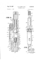
- FIGURE 1 is a side elevational view showing one embodiment of the instrument according to this invention in the fully cocked ready-to-fire position;
- FIGURE 2A is an enlargement in cross section taken on line 2A2A of FIGURE 1 showing the instrument loaded with a cartridge;
- FIGURE 2B is an enlargement being a continuation of FIGURE 2A in cross section taken on line 2B-2B showing the instrument loaded with an ampoule, and both figures showing the instrument in the FIGURE 1 position;
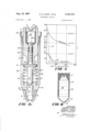
- FIGURE 3A is an enlarged side elevational view in cross section comparable to FIGURE ⁇ 2A taken at the moment the instrument has been fired;
- FIGURE 3B is an enlarged side elevational view in cross section comparable to FIGURE 23, being a continuation of FIGURE 3A;
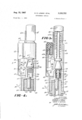
- FIGURE 4A is an enlarged side elevational view partly in cross section showing the rear part separated and in the open position for cartridge extraction;
- FIGURE 4B is an enlarged side elevational view partly in cross section showing the front part of the instrument adjusted for another level of dosage and separated in the open position safe loading with another cartridge;
- FIGURE is a graphical representation of typical pressure-time and velocity time profiles obtainable with the instrument of this invention.
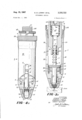
- FIGURE 6 is a side elevational view showing the improved ampoule in cross section.
- the instrument of this invention involves an ampoule and explosive cartridge containing front portion 1 and a rear portion 2 which contains a firing mechanism assembly.
- the front assembly has an ampoule-mounting housing 3 having an axial bore 4 for receiving the ampoule 5 and the front end of a piston 6, the reduced rear end 7 of which is slidably carried in an axial bore 8 of a barrel member 9.
- a nose cap 10 Threadedly mounted on the front end of housing 3 is a nose cap 10 which has a central recess 11 forming an extension of the housing bore 4.
- This cap serves as a skin contacting tip incapable of skin penetration, as a closure for the capsule-containing bore 4 of the housing, and as a front abutment for holding the ampoule 5 in place against the force of piston 6.
- the nose cap has an opening 12 in its front end to permit the ampoule tip 13, pierced by a minute orifice 14, to protrude for contact of the ampoule directly with the skin.
- Housing 3 extends rearwardly in the form of an outer sleeve 18 which is threadedly mounted for longitudinal adjustment on the barrel member at internal threads 19 mating with the external threads 20 of the barrel member. Control of the dosage expelled from the ampoule orifice 14 is obtained by a longitudinal adjustment at these threads as the outer sleeve 18 is held as a front handle portion or turned, as the case may be, in order to obtain the necessary relative motion between housing 3 and barrel member 9 thereby varying the spacing between cap 10 and piston 6 backed up against barrel 9 at the piston flange 16 for providing the customary predischarge of excess medicament and bubbles, if any.
- breech plug 21 Mounted on the rear end of the barrel member is a breech plug 21 having a chamber 22 open to the rear for receiving the explosive cartridge 23 and also having a male thread connection 24 for detachably mounting the rear portion 2 at its female thread 25 as a rear handle assembly comprising a receiver body 26 housing a cartridge firing mechanism including firing pin 27 and the trigger bar 50 for setting off the cartridge.
- the internal mechanism of the front portion 1 includes not only the piston 6 but also a piston return spring one end of which abuts the housing 3 and the other end of which abuts the piston flange 16 as the spring is mounted in compression for retracting the piston to its initial position as at FIGURE 2B or FIGURE 4B. Also included within the sleeve 18 of the front portion is some buffering device such as a suitable ring 30 of soft copper, lead, or the like adapted to deform, preferably plastically, and thereby dissipate the excess energy in the event ampoule 5 is inadvertently omitted and the instrument fired. Avoidance of damage is thus assured.
- spring 15 After firing and injection, spring 15 remains for a time as shown in FIGURE 3B until disengagement of threads 24 and 25 is begun. At this point, piston 6 and spring 15 help keep the gas pressure up and assist cartridge ejection.
- Piston flange 16 carries a circumferential colored band 31 of a readily visible nature for observation of an indicia of the dosage setting desired through a sleeve opening 32 formed in the side of the sleeve together with dosage gauge 4 markings along the side of the opening showing how much of the ampoule charge remains after predischarge.
- any suitable dosage lock such as collar 33 carried threadedly on sleeve 18 to longitudinally move the collar and its resilient chuck fingers to put their tapered ends into Wedging engagement between the cylindrical surface of the barrel 9 and a mating taper carried on the interior of sleeve 18.
- a firing pin striker 41 and a striker spring 42 biasing the striker forwardly as the spring along with the shank of the striker extend rearwardly into and are held in place by a retainer 43 threadedly mounted to the rear end of body 26.
- a retainer 43 Threadedly mounted to the rear end of body 26.
- the retainer at this hearing guides the shank or rear end of the striker and permits it to protrude slidably to the rear for attachment of the cocking handle 45 outside the retainer.
- striker 41 and spring 42 are mounted in the receiver body and the retainer.
- the striker cooperates with a scar 46 which is in the form of a pitman lever pivotally mounted in a side slot 47 by a scar mounting pin 48 carried transversely in the receiver body 26.
- a scar 46 which is in the form of a pitman lever pivotally mounted in a side slot 47 by a scar mounting pin 48 carried transversely in the receiver body 26.
- slot 47 opens into bore 40.
- the striker has a firing pin striking end 28 and a cocking shoulder 49 extending as a notch circumferentially around the front end of its head for engagement with the sear 46 when handle 45 is pulled all the way back. This cocks the instrument and puts it in the ready-to-fire condition shown in FIGURES 1 and 2.
- the sear is actuated by a longitudinally slidable trigger bar 50 which has a sear slot 51 formed intermediate its ends "for receiving the heel 52 of the sear so that the toe 53 of the sear may be rocked out of engagement with the striker at mating notched shoulder 49 of the striker, which is thus released as shown in FIGURE 3 to accomplish firing and injection.
- This is done as the trigger bar is moved forward longitudinally over slot 47 against the bias of trigger return spring 54 by a manual thrust applied either to trigger button 55 fixed (e.g. molded) on the rear end of the trigger bar, or to a trigger thumb piece 56 which may be fixed near the front end of the bar.
- Striker 41 has at the rear end of its head a circuIn ferential ridge 57 extending radially outwardly sufficiently so that after the striker and manual thrust are released, the sear toe 53 may come to rest upon the ridge where it is held outwardly to hold the heel 52 and trigger bar 50 forwardly.
- the front end extension of the bar 50 forming a detent 58, extends into locking notch 59 of external flange 29 formed as part of the front portion 1 to keep the rearward portion 2 locked to the front portion 1.
- the striker head has a deep groove 60 together with a conical taper or sear cam 61 extending circumferentially and inwardly to a diameter less than that of either the cocking shoulder 49 or ridge 57.
- the firing mechanism When the sear toe 53 rests in groove 60, as shown in FIGURE 4A, the firing mechanism is held in a safety position, i.e., with the striker 41 held back off the firing pin 27 and the safety detent 58 at the front end of the trigger bar, retracted from the safety notch 59 of the external flange 29 of the plug 21, fixed to barrel 9.
- the rear or firing portion 2 of the instrument may be unlocked from the front portion 1 so that these portions can be unscrewed or screwed together operably for cartridge extraction and loading.
- Slot 47 formed as an opening through a side of body 26 has in it the sear and also extending into and over it a U-shaped trigger guard 62 in which sear 46 is carried for pivoting on pin 48 by which, together with guard pin 64, the guard is fixed to receiver body 26.
- the guard which may have an extension 62A extending alongside handle 45, extends protectively at least partly around bar 50 and is open at the rear to permit the cocking handle 45 and trigger button 55 to protrude for manual operation.
- Extension 62A has appendage 62B for retaining spring 54 in button 55.
- the front end of the guard 62 is open to permit the trigger bar 50 to also extend forwardly sufficiently so that its front end, defining the safety detent 58, may extend for movement into and out of notch 59.
- Circumferential flange 29, integral with and extending outwardly from the breech plug 21 acts as a stop for the receiver body when it is screwed down all the way to close the breech and as a stop against which the barrel is screwed down in assembly with the plug.
- Notch 59 is in a predetermined location on the circumference so that it is aligned with trigger bar 50 only when receiver body 26 is screwed down fully.
- the receiver body For mounting of the firing pin 27 the receiver body has a firing pin well 34 and a firing pin aperture 35 aligned with eccentric bore 40 and striker 41.
- This well threadedly receives a firing pin housing 36 in which the pin is slidably mounted together with a firing pin spring 37 and a sealing O-ring 38 carried in an external circumferential groove formed in the firing pin to prevent escape of any gas between the head of the firing pin and the opening 39 formed in the pin housing at which the firing pin head protrudes rearwardly to be acted on by the striker.
- the receiver body also has at the bottom of the connection having female threads 25 a cartridge head recess 63 the side walls of which are preferably tapered rearwardly and outwardly so that when cartridge 23 is fired its rim may expand into the tapered side wall for extraction.
- the firing pin aperture 35 opens into recess 63 for acting percussively on the primed rim of the cartridge.
- This system which makes for quietness comprises not only the piston 6 but also the high pressure combustion chamber 65, the venturi orifice 66, and the expansion chamber 67 having insulating liner 68.
- This liner may advantageously be of laminated construction and include porous materials such as aluminum oxide or a fine silica compound known as Sil-O-Cel.
- the liner may be reinforced with Fiberglas; it may be further extended to overlay the front face of the breech plug 21 leaving open only the orifice 66, formed in the plug along with chamber 65. Plug 21 secures the liner.
- the system is readily actuated by a .22 cartridge having only a few grams of suitable propellant discharged upon ignition into chamber 65 designed together with orifice 66 to provide a propellant burning sustaining pressure of the order of about 30,000 p.s.i. or 25,000 psi. (broken curve A), for example, for a suitable smokeless powder.
- a propellant burning sustaining pressure of the order of about 30,000 p.s.i. or 25,000 psi.
- broken curve A for example, for a suitable smokeless powder.
- the initial pressure acting against the piston in insulated chamber 67 is of the order of about 10,000 psi. (solid curve B) and thereafter falls gradually to an injection sustaining pressure level adequate to discharge all or the remaining part of the ampolue contents.
- the explosive force of the energy storing cartridge is thus advantageously modified before it acts on the piston 6 the rear end 7 of which is provided with a suitable number of circumferential grooves and O-rings 70 for sealing the barrel bore 8 against excessive leakage.
- the piston At its front end the piston has a plunger 71 designed to be received snugly in the rear end of an ampoule.
- the plunger has a central tip 72 forming a reduced extension of the nose for acting first on the center of the ampoule stopper.
- the improved ampoule 5 of FIGURE 6 has a tubular sleeve 75 forming a cylindrical side wall of transparent material of acceptable strength such as polypropylene, acrylic, polycarbonate, nylon, or the like of a length for reception over nearly all of the length of housing bore 4 with a snug fit.
- the exterior of the sleeve preferably has a reduced diameter 76 for afiixing a stainless high strength nose such as a stainless steel nose piece or head 77 having a thickness of no more than about 0.020 of an inch and a tip 13 of increased thickness around a minute orifice 14 having a diameter of about 0005-0010 of an inch.
- housing bore 4 is made very long compared to the longitudinal depth of nose cap recess 11 made as shallow as possible.
- Steel nose piece 77 preferably extends back over sleeve 75 only far enough to overlie whatever circular parting line occurs between bore 4 and recess 11. This gives maximum visibility and strength in the ampoule.
- the interior of the ampoule contains medicament charge 78 and is closed at the rear end by a stopper 17 of neoprene rubber or the like elastomer compatible with the charge 78. Since the thickness ofthe transparent ampoule sleeve usually exceeds that of the stainless steel piece 77, which may be drawn quite thin, sleeve 75 may be of uniform diameter inside and outside and be assembled to piece 77 of somewhat larger outside diameter.
- Nose cap 10 is unscrewed and a sterile ampoule inserted in its recess 11 for due examination after which the cap is replaced and turned down to lock the ampoule in the capsule receiving bore of the housing ready for predisc'harge accomplished as dosage sleeve 18 and receiver 26- are turned with respect to each other until the proper selection is indicated at sleeve opening 32.
- Locking collar 33 is then reti'ghtened.
- the injector may be loaded first with cartridge 23 and then with an am poule.
- Injection is done by pushing either button 55 or finger piece 56, whichever is the most convenient.
- the injector rear portion 2 is unscrewed to expose the spent cartridge 80 shown in FIG- URE 4 attached to receiver body 26 at the extracting cartridge head recess 63 from whence it can be easily discarded.
- the axial length of engagement between male thread connection 24 and female thread 25 is preferably greater than the length of the spent cartridge 80 so that residual gas is received in receiver body 26 while some portion of these threads are still in engagement while providing a passage for bleeding off the gas along the threads.
- the nose cap is unscrewed to allow the spent ampoule to be discarded.
- a hypodermic injector for percutaneous injection of liquid medicament from an ampoule having a movable stopper and a jet orifice, said injector comprising an elongated body having a breech end and a front end, an ampoule holder and front abutment mounted on the front end of said body, a single piston slidably mounted within said body for longitudinal movement from an initial *ready-to-drive position to a final driven position, said piston having a plunger adapted for being put into engagement with said stopper and subsequently driving said stopper while so engaged from said initial engagement toward said orifice for discharging said medicament, means for returning said plunger to said initial position, means for initially and longitudinally adjusting the relative positions of said holder and said piston thereby controlling the dosage of medicament to be discharged, and power means for driving said plunger with said first a high fluid impulse followed by a gradually decreasing and steadying fluid force, said power means including means (a) for receiving a cartridge storing the driving energy and releasing it by generating a driving gas at
- said abutment retaining said piston in said injector against overdriving beyond said final position, said means between the cartridge and plunger including a small combustion chamber, a large expansion chamber, said chambers being connected by a venturi orifice, and heat insulating means associated with said expansion chamber.
- a hypodermic injector actuated by gases generated by an explosive for dispensing liquid medicament from an ampoule
- said injector including barrel means, ampoule holding means attached to one end of said barrel means, piston means slideably mounted within said barrel means and having a plunger adapted for engaging an ampoule, explosive receiving means at the other end of said barrel means, and means adapted for firing an explosive positioned in said explosive receiving means
- the improvement comprising gas transfer means between said explosive receiving means and said piston means including first and second chambers and a metering passageway connecting said first and second chambers, said gas transfer means operable to convert the rapidly expanding high pressure gas generated by the firing of an explosive into said first chamber in communication with said explosive receiving means to a lower pressure and slower expansion of the gas bled through said metering passageway into the second chamber, and means in said second chamber for retarding the decay of pressure of the gas acting upon the piston.
- a hypodermic injector actuated by gases generated by an explosive for dispensing liquid medicament from an ampoule
- said injector including barrel means, ampoule holding means attached to one end of said barrel means, piston means slideably mounted within said barrel and having a plunger adapted for engaging an ampoule, explosive receiving means at the other end of said barrel means, and means adapted for firing an explosive positioned in said explosive receiving means
- the improvement comprising gas transfer means between said explosive receiving means and said piston means including first and second chambers and a metering passageway connecting said first and second chambers, said gas transfer means operable to convert the rapidly expanding high pressure gas generated by the firing of an explosive into said first chamber in communication with said explosive receiving means to a lower pressure and slower expansion of the gas bled through said metering passageway into the second of said chambers, and heat insulating means in said second chamber for retarding the decay of pressure of the gas acting on the piston.
- a hypodermic injector operable by propellant gas generated from the firing of an explosive cartridge for percutaneous injection from an ampoule having a movable stopper and mounted in an injector comprising barrel means including cartridge receiving means, piston means received within said barrel means, ampoule holding means mounted on said barrel means and including a perforated nose cap detachably mounted on the front end of said holding means for defining an ampoule-receiving cavity, a high pressure combustion chamber in communication with said cartridge receiving means, an expansion chamber, a venturi orifice between said combustion chamber and said expansion chamber, and bore means for mounting said piston for movement from an ampoule stopper engaging position to a final position under the impetus of gas generated in said combustion chamber, bled off through said orifice, and finally applied from said expansion chamber to said piston, said expansion chamber being volumetrically larger than said combustion chamber and including insulated wall means for minimizing heat loss from said finally applied gas.
- a hypodermic injector actuated by explosive energy from an explosive cartridge for driving liquid medicament from an ampoule percutaneously comprising a barrel having a breech end and a front end having a bore, an ampoule holder connected to said barrel and formed with a bore passing therethrough in alignment with'said barrel bore and in communication therewith, a piston slideably mounted in said barrel bore for reciprocating movement between a final position with respect to said holder and an initial position with respect to said barrel, said piston carrying a plunger portion extending into said holder bore, cartridge firing means connected to said breech end, explosive energy transfer means in said barrel including a combustion chamber communicating with said firing means, an expansion chamber communicating with said barrel bore, a venturi orifice interconnecting said chambers, said energy transfer means defining a closed system for modifying the characteristics of the energy before it is applied to said piston at said expansion chamber to drive said piston to its final position, a breech end closure including firing means disengageably connected to the breech end of said barrel, and a rim-
- a hypodermic injector actuated by explosive energy from an explosive cartridge for driving liquid medicament from an ampoule percutaneously comprising a barrel having a breech end and a front end having a bore, an ampoule holder connected to said barrel and formed with a bore passing therethrough in alignment with said barrel bore and in communication therewith, a piston slideably mounted in said barrel .bore for reciprocating movement between a final position with respect to said holder and an initial position with respect to said barrel, said piston carrying a plunger portion extending into said holder bore, cartridge firing means connected to said breech end, explosive energy transfer means in said barrel including a combustion chamber communicating with said firing means, an expansion chamber communicating with,said barrel bore, a venturi orifice interconnecting said chambers, said energy transfer means defining a closed systern for modifying the characteristics of the energy before it is applied to said piston at said expansion chamber to drive said piston to its final position, a piston return spring for retracting the piston to the initial position, and a closure disengageably connected to
- a hypodermic injector actuated by explosive energy from an explosive cartridge for driving liquid medicament from an ampoule percutaneously comprising a barrel having a breech end and a front end having a bore, an ampoule holder connected to said barrel and formed with a bore passing therethrough in alignment with said barrel bore and in communication therewith, a piston slideably mounted in said barrel bore for reciprocating movement between a final position with respect to said holder and an initial position with respect to said barrel, said piston carrying a plunger portion extending into said holder bore, cartridge firing means connected to said breech end, explosive energy transfer means in said barrel including a combustion chamber communicating with said firing means, an expansion chamber communicating with said barrel bore, a venturi orifice interconnecting said chamber, said energy transfer means defining a closed system for modifying the characteristics of the energy before it is applied to said piston at said expansion chamber to drive said piston to its final position, said holder being threadedly connected to the barrel with longitudinal adjustability, said firing means and breech end being threadedly engageable,
- a hypodermic injector actuated by explosive energy from an explosive cartridge for driving liquid medicament from an ampoule percutaneously comprising a barrel having a breech end and a front end having a bore, an ampouleholder connected to said barrel and formed with a bore passing therethrough in alignment with said barrel bore and in communication therewith, a piston slideably mounted in said barrel bore for reciprocating movement between a final position with respect to said holder and an initial position with respect to said barrel, said piston carrying a plunger portion extending into said holder bore, cartridge firing means connected to said breech end, explosive energy transfer means in said barrel including a combustion chamber communicating with said firing means, an expansion chamber communicating with said barrel bore, and a venturi orifice interconnecting said chambers, said energy transfer means defining a closed system for modifying the characteristics of the energy before it is applied to said piston at said expansion chamber to drive said piston to its final position, said firing means including a firing pin, a firing pin striker forwardly biased toward said pin and adapted to be manually pulled back to a
- a method of hypodermic injection the steps of (a) providing a charge of liquid medicament enclosed and supported except for a jet orifice and positioned in alignment With a piston engaging a stopper associated with said charge, (b) explosively generating a propellant fluid at a pressure including a high pressure peak in a first enclosed volume designed to sustain the combustion to substantial completion, (c) bleeding said propellant fluid through a venturi passageway to a second enclosed volume to effect expansion and reduction of said pressure peak in said second volume, and, (d) applying the bled fluid from said second volume to said piston at said reduced peak pressure followed by a gradually lowered and flattened off pressure while retarding the loss of heat from said applied fluid at least in said expansion volume to drive said piston at said reduced high pressure peak for initially discharging a fine stream of said medicament at a velocity such that percutaneous penetration is accomplished and to continue the discharging for lodging of said medicament within the underlying tissue with a minimum of fluid pressure surge and fluctuation as said piston is further driven at said gradually lowered and flattened off
Description
1967 E. D. LowRY ET AL R 3,335,722
- HYPODERMIC DEVICE Fi led'Nov. 1; 1963 4 Sheets-Sheet 1 Z5 INVENTORS,
EDWARD 0. LOW/RV GORDON J. l OELZ GARDNER H PERRY DAV/D F BUTLER ATTORNEY Aug; 15, 1967 E. p. LOWRY ETALE 3,
' HYPODERMIYC DEVICE 4 Sheets- Sheet Filed Nov; '1', 1963 I NVEN TORS' 4 EDWARD D4 LOWRV GORDON J VOELZ GARDNER H. PERRY DAV/D E BUTLER v A TTOR/VEV E. p. LowRY IDETAL 7 3,335,722
' HYPODERMIC DEVICE 4 Sheets-Sheet 4 Filed Nov.
INVENTORS EDWARD D. LOl l RV GORDON J GARDNER H.
I/OELZ RERRV DAV/D F BUTLER ATTORNEY United States Patent 3,335,722 HYPODERMIC DEVICE Edward D. Lowry, Branford, Gordon J. Voelz, New
Haven, Gardner H. Perry, Madison, and David F. But- I ler, Hamden, Conn., assignors to Olin Mathieson Chemical Corporation, a corporation of Virginia Filed Nov. 1, 1963, Ser. No. 320,881 12 Claims. (Cl. 128-173) This invention relates to administration of medication and more specifically to a needleless hypodermic medicator or injector capable of performing percutaneous inoculation and the like.
Medicators of this type have been made using either a blank explosive cartridge or a complicated arrangement of springs to actuate the instrument; this has been attended by various disadvantages.
With direct explosive actuation, there is an excessive pressure peak followed by too rapid decay of force. Where both the medicament and the explosive are loaded in the same capsule or cylinder separated only by a slidable stopper, there is danger of mutual contamination so that neither the medicament nor the explosive may be effective for their intended purpose. The inclusion of a space between the explosive cartridge and the stopper has not precluded this danger. There has also been the further hazard of driving hot gas bubbles into the medicament during injection.
Spring actuation makes such instruments considerably more complicated in structure and in operation. Storing all the required energy in springs makes cocking difficult and time consuming. Moreover, the required pressure characteristics have made it necessary to go to a highlow, two-stage system of many springs together with force changers which add to the complexity.
Excessive pressure peaks, surges, and/or fluctuations are encountered in not only the heretofore known exposive cartridge systems (US. Patents Nos. 2,322,244 and 2,322,245) but also in the spring systems. Some patients experience this as pain.
This invention contemplates provision of a single plunger-acutated injector having a special explosiveactuated stage in the injector adapted to transfer energy between the explosive and ampoule to discharge liquid medicament with desired jet velocity-time and propellant fluid pressure-time characteristics to achieve penetration of the epidermis followed by dosing. Under the impulse of combustion of an explosive charge, the desired variation of velocity and pressure is obtained during an effective time of injection because a feature of this invention is a novel closed system in this stage for generating, modifying, and then applying the explosively generated force to the ampoule, indirectly by means of a plunger or piston acting on the ampoule, isolated thus against contamination.
' By applying driving gas generated from a propellant of either the solid or liquid type (ethyl nitrate, for example, mixed with normal propyl nitrate) through two chambers and an intervening venturi orifice or the like pressure reducing means to a sealing piston at the second or expansion chamber having walls of novel heat insulated construction, it was found possible to produce an initial impulse of proper high magnitude .at the ampoule for initiation of injection followed by a gradually dropping force for proper completion of injection over an extended interval of time. The propellant charge, usually formed as a cartridge, is ignited for firing preferably in a small chamber which is connected to a larger surge chamber 'by an orifice forming a metering passageway. When the propellant is ignited, it generates a very high pressure in the small chamber, since the gases take some time to pour through the orifice. By proper design of the two chambers and the orifice, it is possible to raise the pressure in the small chamber to a sustaining pressure, which will essentially guarantee full combustion. After a few milliseconds the gas in the high pressure chamber will flow through the orifice and the pressure in both chambers Will be equalized to maintain the proper pressures in the two chambers.
It will be necessary to keep the gases confined for at least the time interval of the stroke, which is roughly one-quarter of a second, i.e., some 250 milliseconds. This is a very long time period for a one-shot interior ballistic system and since the gases are at least temporarily trapped, they ordinarily have time to cool and deposit undesirable residue. The unburnt remains of an incomplete combustion can be eliminated by the ballistic system which would guarantee essentially complete combustion. The use of a removable insulator sleeve of solid or porous silicones, polyolefins, nylon, micarta, polyurethane, or the like as a liner over at least most of the wall area of the expansion chamber fulfills the function, not only of reducing heat loss to the walls but also of collecting the combustion residue. Thus, after about some 50 shots the removable insulator sleeve can be discarded and replaced with a new one. The liner may be carried as a layer or coating on a thin metal insert.
Another feature of the invention is a novel ampoule having a side wall transparency to permit observation of the contents of the ampoule while maintaining adequate strength in the containing walls.
Another feature is in the inclusion of arrangements for using the breech and firing mechanism to aid safe assembly and disassembly, and for using residual gas pressure and plunger return to aid extraction of the spent cartridge of propellant.
One object of the invention, therefore, is the provision of a novel explosive actuated medicator for performing percutaneous inoculation, or other injection painlessly.
Another object of this invention is to provide a simple, low-cost, portable instrument receiving an explosive propellant for discharging a fine stream or jet of liquid medicament from an ampoule at improved pressures and velocities.
Another object is to provide an explosive operated hypodermic instrument of improved construction with respect to quietness, speed, and ease of operation and with respect to safety.
Another object is provision of a new and improved ampoule.
Still another object is to provide a hypodermic device and method operable to accomplish explosive actuation and percutaneous medication at desired depths and dosages with convenience, reliability, and safety from a jet ampoule.
Other advantages and objects will be apparent from a detailed description of the illustrated embodiment when read in connection with the accompaning drawing in which:
FIGURE 1 is a side elevational view showing one embodiment of the instrument according to this invention in the fully cocked ready-to-fire position;
FIGURE 2A is an enlargement in cross section taken on line 2A2A of FIGURE 1 showing the instrument loaded with a cartridge;
FIGURE 2B is an enlargement being a continuation of FIGURE 2A in cross section taken on line 2B-2B showing the instrument loaded with an ampoule, and both figures showing the instrument in the FIGURE 1 position;
FIGURE 3A is an enlarged side elevational view in cross section comparable to FIGURE {2A taken at the moment the instrument has been fired;
FIGURE 3B is an enlarged side elevational view in cross section comparable to FIGURE 23, being a continuation of FIGURE 3A;
FIGURE 4A is an enlarged side elevational view partly in cross section showing the rear part separated and in the open position for cartridge extraction;
FIGURE 4B is an enlarged side elevational view partly in cross section showing the front part of the instrument adjusted for another level of dosage and separated in the open position safe loading with another cartridge;
FIGURE is a graphical representation of typical pressure-time and velocity time profiles obtainable with the instrument of this invention; and
FIGURE 6 is a side elevational view showing the improved ampoule in cross section.
With reference to the drawing, the instrument of this invention involves an ampoule and explosive cartridge containing front portion 1 and a rear portion 2 which contains a firing mechanism assembly.
The front assembly has an ampoule-mounting housing 3 having an axial bore 4 for receiving the ampoule 5 and the front end of a piston 6, the reduced rear end 7 of which is slidably carried in an axial bore 8 of a barrel member 9. Threadedly mounted on the front end of housing 3 is a nose cap 10 which has a central recess 11 forming an extension of the housing bore 4. This cap serves as a skin contacting tip incapable of skin penetration, as a closure for the capsule-containing bore 4 of the housing, and as a front abutment for holding the ampoule 5 in place against the force of piston 6. The nose cap has an opening 12 in its front end to permit the ampoule tip 13, pierced by a minute orifice 14, to protrude for contact of the ampoule directly with the skin.
Housing 3 extends rearwardly in the form of an outer sleeve 18 which is threadedly mounted for longitudinal adjustment on the barrel member at internal threads 19 mating with the external threads 20 of the barrel member. Control of the dosage expelled from the ampoule orifice 14 is obtained by a longitudinal adjustment at these threads as the outer sleeve 18 is held as a front handle portion or turned, as the case may be, in order to obtain the necessary relative motion between housing 3 and barrel member 9 thereby varying the spacing between cap 10 and piston 6 backed up against barrel 9 at the piston flange 16 for providing the customary predischarge of excess medicament and bubbles, if any.
Mounted on the rear end of the barrel member is a breech plug 21 having a chamber 22 open to the rear for receiving the explosive cartridge 23 and also having a male thread connection 24 for detachably mounting the rear portion 2 at its female thread 25 as a rear handle assembly comprising a receiver body 26 housing a cartridge firing mechanism including firing pin 27 and the trigger bar 50 for setting off the cartridge.
The internal mechanism of the front portion 1 includes not only the piston 6 but also a piston return spring one end of which abuts the housing 3 and the other end of which abuts the piston flange 16 as the spring is mounted in compression for retracting the piston to its initial position as at FIGURE 2B or FIGURE 4B. Also included within the sleeve 18 of the front portion is some buffering device such as a suitable ring 30 of soft copper, lead, or the like adapted to deform, preferably plastically, and thereby dissipate the excess energy in the event ampoule 5 is inadvertently omitted and the instrument fired. Avoidance of damage is thus assured.
After firing and injection, spring 15 remains for a time as shown in FIGURE 3B until disengagement of threads 24 and 25 is begun. At this point, piston 6 and spring 15 help keep the gas pressure up and assist cartridge ejection.
Piston flange 16 carries a circumferential colored band 31 of a readily visible nature for observation of an indicia of the dosage setting desired through a sleeve opening 32 formed in the side of the sleeve together with dosage gauge 4 markings along the side of the opening showing how much of the ampoule charge remains after predischarge.
To lock and unlock the dosage sleeve 18 in the selected position, there is provided any suitable dosage lock such as collar 33 carried threadedly on sleeve 18 to longitudinally move the collar and its resilient chuck fingers to put their tapered ends into Wedging engagement between the cylindrical surface of the barrel 9 and a mating taper carried on the interior of sleeve 18.
Extending longitudinally in an eccentric bore 40 in the receiver body 26 is the head of a firing pin striker 41 and a striker spring 42 biasing the striker forwardly as the spring along with the shank of the striker extend rearwardly into and are held in place by a retainer 43 threadedly mounted to the rear end of body 26. Formed with a central bearing 44, the retainer at this hearing guides the shank or rear end of the striker and permits it to protrude slidably to the rear for attachment of the cocking handle 45 outside the retainer. Thus, striker 41 and spring 42 are mounted in the receiver body and the retainer.
The striker cooperates with a scar 46 which is in the form of a pitman lever pivotally mounted in a side slot 47 by a scar mounting pin 48 carried transversely in the receiver body 26. To carry sear 46 in operative association with the striker, slot 47 opens into bore 40.
The striker has a firing pin striking end 28 and a cocking shoulder 49 extending as a notch circumferentially around the front end of its head for engagement with the sear 46 when handle 45 is pulled all the way back. This cocks the instrument and puts it in the ready-to-fire condition shown in FIGURES 1 and 2.
To accomplish release, the sear is actuated by a longitudinally slidable trigger bar 50 which has a sear slot 51 formed intermediate its ends "for receiving the heel 52 of the sear so that the toe 53 of the sear may be rocked out of engagement with the striker at mating notched shoulder 49 of the striker, which is thus released as shown in FIGURE 3 to accomplish firing and injection. This is done as the trigger bar is moved forward longitudinally over slot 47 against the bias of trigger return spring 54 by a manual thrust applied either to trigger button 55 fixed (e.g. molded) on the rear end of the trigger bar, or to a trigger thumb piece 56 which may be fixed near the front end of the bar.
Striker 41 has at the rear end of its head a circuIn ferential ridge 57 extending radially outwardly sufficiently so that after the striker and manual thrust are released, the sear toe 53 may come to rest upon the ridge where it is held outwardly to hold the heel 52 and trigger bar 50 forwardly. The front end extension of the bar 50, forming a detent 58, extends into locking notch 59 of external flange 29 formed as part of the front portion 1 to keep the rearward portion 2 locked to the front portion 1.
Intermediate shoulder 49 and ridge 57, the striker head has a deep groove 60 together with a conical taper or sear cam 61 extending circumferentially and inwardly to a diameter less than that of either the cocking shoulder 49 or ridge 57.
When the sear toe 53 rests in groove 60, as shown in FIGURE 4A, the firing mechanism is held in a safety position, i.e., with the striker 41 held back off the firing pin 27 and the safety detent 58 at the front end of the trigger bar, retracted from the safety notch 59 of the external flange 29 of the plug 21, fixed to barrel 9. In this position, the rear or firing portion 2 of the instrument may be unlocked from the front portion 1 so that these portions can be unscrewed or screwed together operably for cartridge extraction and loading.
From this position, with the instrument assembled it may be locked without cocking by merely pushing the firing button 55 to allow detent 58 of the bar 50 to lock into notch 59. In this locked position the instrument may be turned with respect to sleeve 18 for ampoule loading and dosage adjustment.
Slot 47 formed as an opening through a side of body 26 has in it the sear and also extending into and over it a U-shaped trigger guard 62 in which sear 46 is carried for pivoting on pin 48 by which, together with guard pin 64, the guard is fixed to receiver body 26. The guard, which may have an extension 62A extending alongside handle 45, extends protectively at least partly around bar 50 and is open at the rear to permit the cocking handle 45 and trigger button 55 to protrude for manual operation. Extension 62A has appendage 62B for retaining spring 54 in button 55. The front end of the guard 62 is open to permit the trigger bar 50 to also extend forwardly sufficiently so that its front end, defining the safety detent 58, may extend for movement into and out of notch 59.
Circumferential flange 29, integral with and extending outwardly from the breech plug 21 acts as a stop for the receiver body when it is screwed down all the way to close the breech and as a stop against which the barrel is screwed down in assembly with the plug. Notch 59 is in a predetermined location on the circumference so that it is aligned with trigger bar 50 only when receiver body 26 is screwed down fully. Thus, when the cocking handle 45 is pulled back sufiiciently to engage sear toe 53 with the cocking shoulder 49, the detent extends into the clearance of notch 59, provided portions 1 and 2 are properly assembled. In the event these portions are not screwed down all the way, there is interference between fiange 29 and detent 58; this prevents cocking or firing.
For mounting of the firing pin 27 the receiver body has a firing pin well 34 and a firing pin aperture 35 aligned with eccentric bore 40 and striker 41. This well threadedly receives a firing pin housing 36 in which the pin is slidably mounted together with a firing pin spring 37 and a sealing O-ring 38 carried in an external circumferential groove formed in the firing pin to prevent escape of any gas between the head of the firing pin and the opening 39 formed in the pin housing at which the firing pin head protrudes rearwardly to be acted on by the striker.
The receiver body also has at the bottom of the connection having female threads 25 a cartridge head recess 63 the side walls of which are preferably tapered rearwardly and outwardly so that when cartridge 23 is fired its rim may expand into the tapered side wall for extraction. The firing pin aperture 35 opens into recess 63 for acting percussively on the primed rim of the cartridge.
Improved injector pressure-time and jet velocity-time characteristics of the type shown in FIGURE 5 are obtained because of the closed interior ballistic system pro- -vided between the ampoule stopper 17 and cartridge 23.
This system which makes for quietness comprises not only the piston 6 but also the high pressure combustion chamber 65, the venturi orifice 66, and the expansion chamber 67 having insulating liner 68. This liner may advantageously be of laminated construction and include porous materials such as aluminum oxide or a fine silica compound known as Sil-O-Cel. The liner may be reinforced with Fiberglas; it may be further extended to overlay the front face of the breech plug 21 leaving open only the orifice 66, formed in the plug along with chamber 65. Plug 21 secures the liner.
The system is readily actuated by a .22 cartridge having only a few grams of suitable propellant discharged upon ignition into chamber 65 designed together with orifice 66 to provide a propellant burning sustaining pressure of the order of about 30,000 p.s.i. or 25,000 psi. (broken curve A), for example, for a suitable smokeless powder. At this high pressure discharge from chamber 65 through an orifice 66 having a diameter of about 0.125 of an inch, the initial pressure acting against the piston in insulated chamber 67 is of the order of about 10,000 psi. (solid curve B) and thereafter falls gradually to an injection sustaining pressure level adequate to discharge all or the remaining part of the ampolue contents.
In the absence of liner 68 the terminal pressure will fall too rapidly as illustrated by Curve C.
The explosive force of the energy storing cartridge is thus advantageously modified before it acts on the piston 6 the rear end 7 of which is provided with a suitable number of circumferential grooves and O-rings 70 for sealing the barrel bore 8 against excessive leakage.
At its front end the piston has a plunger 71 designed to be received snugly in the rear end of an ampoule. The plunger has a central tip 72 forming a reduced extension of the nose for acting first on the center of the ampoule stopper.
The improved ampoule 5 of FIGURE 6 has a tubular sleeve 75 forming a cylindrical side wall of transparent material of acceptable strength such as polypropylene, acrylic, polycarbonate, nylon, or the like of a length for reception over nearly all of the length of housing bore 4 with a snug fit. At its front end the exterior of the sleeve preferably has a reduced diameter 76 for afiixing a stainless high strength nose such as a stainless steel nose piece or head 77 having a thickness of no more than about 0.020 of an inch and a tip 13 of increased thickness around a minute orifice 14 having a diameter of about 0005-0010 of an inch.
In order that the length of transparent sleeve 75 may be made as long as possible compared to the length of nose piece 77, housing bore 4 is made very long compared to the longitudinal depth of nose cap recess 11 made as shallow as possible. Steel nose piece 77 preferably extends back over sleeve 75 only far enough to overlie whatever circular parting line occurs between bore 4 and recess 11. This gives maximum visibility and strength in the ampoule.
The interior of the ampoule contains medicament charge 78 and is closed at the rear end by a stopper 17 of neoprene rubber or the like elastomer compatible with the charge 78. Since the thickness ofthe transparent ampoule sleeve usually exceeds that of the stainless steel piece 77, which may be drawn quite thin, sleeve 75 may be of uniform diameter inside and outside and be assembled to piece 77 of somewhat larger outside diameter.
In operation one normally starts with an assembled but unloaded instrument. To prepare for reception of the ampoule 5 locking collar 33 is loosened and then firing button 55 is depressed to lock the barrel 9 and receiver body 26 at notch 59. By holding sleeve 18 the receiver 26 is turned back until more than full dosage is shown by hand 31 at opening 32.
Nose cap 10 is unscrewed and a sterile ampoule inserted in its recess 11 for due examination after which the cap is replaced and turned down to lock the ampoule in the capsule receiving bore of the housing ready for predisc'harge accomplished as dosage sleeve 18 and receiver 26- are turned with respect to each other until the proper selection is indicated at sleeve opening 32. Locking collar 33 is then reti'ghtened.
From this position the next step is to pull back handle 45 slightly until a definite click is heard as sear 46 drops into groove 60 at which detent 5S disengages notch 59 and allows rear portion 2 of the injector to be screwed to exposed a cartridge chamber 22 for insertion of cartridge 23-.
The rear portion is then replaced and screwed down all the way until bar 50 is aligned with notch 59 indicating that the cartridge is properly breeched and the instrument ready for cocking, which is done by pulling the cooking handle 45 as far back as it will go.
Although the foregoing is preferred, the injector may be loaded first with cartridge 23 and then with an am poule.
Injection is done by pushing either button 55 or finger piece 56, whichever is the most convenient.
After use, during and before which detent 58 remains in safety notch 59, the injector rear portion 2 is unscrewed to expose the spent cartridge 80 shown in FIG- URE 4 attached to receiver body 26 at the extracting cartridge head recess 63 from whence it can be easily discarded. In this respect the axial length of engagement between male thread connection 24 and female thread 25 is preferably greater than the length of the spent cartridge 80 so that residual gas is received in receiver body 26 while some portion of these threads are still in engagement while providing a passage for bleeding off the gas along the threads.
Extraction is aided by the residual gas pressure, under the action of return spring 15, as well as by the configuration of recess 63. Normally, piston 6 after firing does not return, despite the bias of spring 15, until disengagement of threads 24 and 25 is begun, because the piston and the gas act on each other.
Finally, the nose cap is unscrewed to allow the spent ampoule to be discarded.
Although the foregoing description relates to what is now believed to be a preferred embodiment, it is to be understood that those skilled in the art may make; changes and modifications without departing from the spirit and scope of the invention as set forth in the appended claims.
What is claimed is:
1. A hypodermic injector for percutaneous injection of liquid medicament from an ampoule having a movable stopper and a jet orifice, said injector comprising an elongated body having a breech end and a front end, an ampoule holder and front abutment mounted on the front end of said body, a single piston slidably mounted within said body for longitudinal movement from an initial *ready-to-drive position to a final driven position, said piston having a plunger adapted for being put into engagement with said stopper and subsequently driving said stopper while so engaged from said initial engagement toward said orifice for discharging said medicament, means for returning said plunger to said initial position, means for initially and longitudinally adjusting the relative positions of said holder and said piston thereby controlling the dosage of medicament to be discharged, and power means for driving said plunger with said first a high fluid impulse followed by a gradually decreasing and steadying fluid force, said power means including means (a) for receiving a cartridge storing the driving energy and releasing it by generating a driving gas at elevated temperature pressure by explosive combustion and expansion, (b) firing means for releasing said energy as generated gas, and (c) conversion means between said cartridge and plunger adapted to permit substantial completion of said combustion at a high sustaining pressure higher than said impulse, bleed-off of said fluid for expansion for applying directly to said plunger a driving pressure less than said sustaining pressure but including said high impulse while inhibiting loss. of heat from said fluid in expansion at said low driving pressure, said abutment retaining said piston in said injector against overdriving beyond said final position, said means between the cartridge and plunger including a small combustion chamber, a large expansion chamber, said chambers being connected by a venturi orifice, and heat insulating means associated with said expansion chamber.
2. In a hypodermic injector actuated by gases generated by an explosive for dispensing liquid medicament from an ampoule, said injector including barrel means, ampoule holding means attached to one end of said barrel means, piston means slideably mounted within said barrel means and having a plunger adapted for engaging an ampoule, explosive receiving means at the other end of said barrel means, and means adapted for firing an explosive positioned in said explosive receiving means, the improvement, comprising gas transfer means between said explosive receiving means and said piston means including first and second chambers and a metering passageway connecting said first and second chambers, said gas transfer means operable to convert the rapidly expanding high pressure gas generated by the firing of an explosive into said first chamber in communication with said explosive receiving means to a lower pressure and slower expansion of the gas bled through said metering passageway into the second chamber, and means in said second chamber for retarding the decay of pressure of the gas acting upon the piston.
3. In a hypodermic injector actuated by gases generated by an explosive for dispensing liquid medicament from an ampoule, said injector including barrel means, ampoule holding means attached to one end of said barrel means, piston means slideably mounted within said barrel and having a plunger adapted for engaging an ampoule, explosive receiving means at the other end of said barrel means, and means adapted for firing an explosive positioned in said explosive receiving means, the improvement comprising gas transfer means between said explosive receiving means and said piston means including first and second chambers and a metering passageway connecting said first and second chambers, said gas transfer means operable to convert the rapidly expanding high pressure gas generated by the firing of an explosive into said first chamber in communication with said explosive receiving means to a lower pressure and slower expansion of the gas bled through said metering passageway into the second of said chambers, and heat insulating means in said second chamber for retarding the decay of pressure of the gas acting on the piston.
4. The injector of claim 3 wherein said heat insulating means is a lining positioned in said second chamber.
5. The injector of claim 4 wherein the lining is replaceably mounted in said second chamber.
6. A hypodermic injector operable by propellant gas generated from the firing of an explosive cartridge for percutaneous injection from an ampoule having a movable stopper and mounted in an injector comprising barrel means including cartridge receiving means, piston means received within said barrel means, ampoule holding means mounted on said barrel means and including a perforated nose cap detachably mounted on the front end of said holding means for defining an ampoule-receiving cavity, a high pressure combustion chamber in communication with said cartridge receiving means, an expansion chamber, a venturi orifice between said combustion chamber and said expansion chamber, and bore means for mounting said piston for movement from an ampoule stopper engaging position to a final position under the impetus of gas generated in said combustion chamber, bled off through said orifice, and finally applied from said expansion chamber to said piston, said expansion chamber being volumetrically larger than said combustion chamber and including insulated wall means for minimizing heat loss from said finally applied gas.
7. The injector of claim 6 wherein said wall means is a replaceable liner substantially of an insulating material.
8. A hypodermic injector actuated by explosive energy from an explosive cartridge for driving liquid medicament from an ampoule percutaneously comprising a barrel having a breech end and a front end having a bore, an ampoule holder connected to said barrel and formed with a bore passing therethrough in alignment with'said barrel bore and in communication therewith, a piston slideably mounted in said barrel bore for reciprocating movement between a final position with respect to said holder and an initial position with respect to said barrel, said piston carrying a plunger portion extending into said holder bore, cartridge firing means connected to said breech end, explosive energy transfer means in said barrel including a combustion chamber communicating with said firing means, an expansion chamber communicating with said barrel bore, a venturi orifice interconnecting said chambers, said energy transfer means defining a closed system for modifying the characteristics of the energy before it is applied to said piston at said expansion chamber to drive said piston to its final position, a breech end closure including firing means disengageably connected to the breech end of said barrel, and a rim-fire cartridge head receiving recess in said closure, said recess being tapered outwardly and to the rear for assisting cartridge extraction.
9. A hypodermic injector actuated by explosive energy from an explosive cartridge for driving liquid medicament from an ampoule percutaneously comprising a barrel having a breech end and a front end having a bore, an ampoule holder connected to said barrel and formed with a bore passing therethrough in alignment with said barrel bore and in communication therewith, a piston slideably mounted in said barrel .bore for reciprocating movement between a final position with respect to said holder and an initial position with respect to said barrel, said piston carrying a plunger portion extending into said holder bore, cartridge firing means connected to said breech end, explosive energy transfer means in said barrel including a combustion chamber communicating with said firing means, an expansion chamber communicating with,said barrel bore, a venturi orifice interconnecting said chambers, said energy transfer means defining a closed systern for modifying the characteristics of the energy before it is applied to said piston at said expansion chamber to drive said piston to its final position, a piston return spring for retracting the piston to the initial position, and a closure disengageably connected to the breech end of said barrel, said piston being substantially sealed in said barrel bore, and said piston and the return spring maintaining residual fluid pressure for assisting cartridge extraction when the closure is disengaged.
10. A hypodermic injector actuated by explosive energy from an explosive cartridge for driving liquid medicament from an ampoule percutaneously comprising a barrel having a breech end and a front end having a bore, an ampoule holder connected to said barrel and formed with a bore passing therethrough in alignment with said barrel bore and in communication therewith, a piston slideably mounted in said barrel bore for reciprocating movement between a final position with respect to said holder and an initial position with respect to said barrel, said piston carrying a plunger portion extending into said holder bore, cartridge firing means connected to said breech end, explosive energy transfer means in said barrel including a combustion chamber communicating with said firing means, an expansion chamber communicating with said barrel bore, a venturi orifice interconnecting said chamber, said energy transfer means defining a closed system for modifying the characteristics of the energy before it is applied to said piston at said expansion chamber to drive said piston to its final position, said holder being threadedly connected to the barrel with longitudinal adjustability, said firing means and breech end being threadedly engageable, said injector including a front handle portion fixed to the holder, a rear handle portion carrying the firing means adapted to be either at safety, or to be cocked and then released for firing the cartridge and carrying a trigger means for releasing the cocked firing means, and detent means associated with the triggermeans and barrel breech and for (a) preventing full threaded engagement of the rear handle portion and breech end unless the firing means is at safety and for (b) releasably locking the rear handle portion and barrel together as a fully engaged unit for movement with respect to the front handle portion when said firing means is either released or cocked so that said rear and front handles may be turned manually with respect to each other after said firing means has been released and so that said rear handle and breech end may not be unlocked for separation when said firing means is cocked.
11. A hypodermic injector actuated by explosive energy from an explosive cartridge for driving liquid medicament from an ampoule percutaneously comprising a barrel having a breech end and a front end having a bore, an ampouleholder connected to said barrel and formed with a bore passing therethrough in alignment with said barrel bore and in communication therewith, a piston slideably mounted in said barrel bore for reciprocating movement between a final position with respect to said holder and an initial position with respect to said barrel, said piston carrying a plunger portion extending into said holder bore, cartridge firing means connected to said breech end, explosive energy transfer means in said barrel including a combustion chamber communicating with said firing means, an expansion chamber communicating with said barrel bore, and a venturi orifice interconnecting said chambers, said energy transfer means defining a closed system for modifying the characteristics of the energy before it is applied to said piston at said expansion chamber to drive said piston to its final position, said firing means including a firing pin, a firing pin striker forwardly biased toward said pin and adapted to be manually pulled back to a cocked ready-to-fire position from either a fired position or an intermediate safety position adjacent said fired position, said cocked position being defined by a first striker shoulder located adjacent the front end of said striker at a given level, a sear adapted to engage with said first shoulder for holding the striker in the cocked position and the sear outwardly, said fired position being defined by a striker surface located back of the first shoulder at a level outwardly of said first shoulder level for engaging with said sear for holding it outwardly, said safety position being defined by a second striker shoulder located adjacent said striker surface at a level inwardly of said surface and first shoulder level for engagement with said sear for holding said striker with the least bias back from said pin and also receiving said sear, inwardly, manually operable trigger means operatively connected with said sear for disengaging it from said first shoulder for firing and also for disengaging it from said second shoulder, means urging said sear into said engagement at one of said surface and shoulders, a detent associated with said trigger means and operative to protrude for engagement with the barrel when said sear is engaged at one of said first shoulder and surface thereby preventing either full connection of the firing means to the barrel breech end or disconnection of the same, said detent being retracted out of said barrel engagement when said sear engages said second shoulder thereby permitting connection and disconnection of said firing means and breech end.
12. In a method of hypodermic injection the steps of (a) providing a charge of liquid medicament enclosed and supported except for a jet orifice and positioned in alignment With a piston engaging a stopper associated with said charge, (b) explosively generating a propellant fluid at a pressure including a high pressure peak in a first enclosed volume designed to sustain the combustion to substantial completion, (c) bleeding said propellant fluid through a venturi passageway to a second enclosed volume to effect expansion and reduction of said pressure peak in said second volume, and, (d) applying the bled fluid from said second volume to said piston at said reduced peak pressure followed by a gradually lowered and flattened off pressure while retarding the loss of heat from said applied fluid at least in said expansion volume to drive said piston at said reduced high pressure peak for initially discharging a fine stream of said medicament at a velocity such that percutaneous penetration is accomplished and to continue the discharging for lodging of said medicament within the underlying tissue with a minimum of fluid pressure surge and fluctuation as said piston is further driven at said gradually lowered and flattened off pressure.
(References on following page) 1 1 References Cited UNITED STATES PATENTS 6/1943 Lockhart 128173 6/1943 Lockhart 128173 8/1952 Smoot 128--173 7/1953 Scherer 128173 12 2,680,439 6/1954 Sutermeister 128173 2,762,370 9/1956 Venditty 128-173 3,131,692 5/1964 LOVe 128-218 X 5 RICHARD A. GAUDET, Primary Examiner.
W. E. KAMM, Assistant Examiner.
Claims (1)
- 2. IN A HYPODERMIC INJECTOR ACTUATED BY GASES GENERATED BY AN EXPLOSIVE FOR DISPENING LIQUID MEDICAMENT FROM AN AMPOULE, SAID INJECTOR INCLUDING BARREL MEANS, AMPOULE HOLDING MEANS ATTACHED TO ONE END OF SAID BARREL MEANS, PISTON MEANS SLIDEABLY MOUNTED WITHIN SAID BARREL MEANS AND HAVING A PLUNGER ADAPTED FOR ENGAGING AN AMPOULE, EXPLOSIVE RECEIVING MEANS AT THE OTHER END OF SAID BARREL MEANS, AND MEANS ADAPTED FOR FIRING AN EXPLOSIVE POSITIONED IN SAID EXPLOSIVE RECEIVING MEANS, THE IMPROVEMENT, COMPRISING GAS TRANSFER MEANS BETWEEN SAID EXPLOSIVE RECEIVING MEANS AND SAID PISTON MEANS INCLUDING FIRST AND SECOND CHAMBERS AND A METERING PASSAGEWAY CONNECTING SAID FIRST AND SECOND CHAMBERS, SAID GAS TRANSFER MEANS OPERABLE TO CONVERT THE RAPIDLY EXPANDING HIGH PRESSURE GAS GENERATED BY THE FIRING OF AN EXPLOSIVE INTO SAID FIRST CHAMBER IN COMMUNICATION WITH SAID EXPLOSIVE RECEIVING MEANS TO A LOWER PRESSURE AND SLOWER EXPANSION OF THE GAS BLED THROUGH SAID METERING PASSAGEWAY INTO THE SECOND CHAMBER, AND MEANS IN SAID SECOND CHAMBER FOR RETARDING THE DECAY OF PRESSURE OF THE GAS ACTING UPON THE PISTON.
Priority Applications (1)
| Application Number | Priority Date | Filing Date | Title |
|---|---|---|---|
| US320881A US3335722A (en) | 1963-11-01 | 1963-11-01 | Hypodermic device |
Applications Claiming Priority (1)
| Application Number | Priority Date | Filing Date | Title |
|---|---|---|---|
| US320881A US3335722A (en) | 1963-11-01 | 1963-11-01 | Hypodermic device |
Publications (1)
| Publication Number | Publication Date |
|---|---|
| US3335722A true US3335722A (en) | 1967-08-15 |
Family
ID=23248218
Family Applications (1)
| Application Number | Title | Priority Date | Filing Date |
|---|---|---|---|
| US320881A Expired - Lifetime US3335722A (en) | 1963-11-01 | 1963-11-01 | Hypodermic device |
Country Status (1)
| Country | Link |
|---|---|
| US (1) | US3335722A (en) |
Cited By (37)
| Publication number | Priority date | Publication date | Assignee | Title |
|---|---|---|---|---|
| US3379176A (en) * | 1965-10-20 | 1968-04-23 | Miller Herman Inc | Livestock identification method and apparatus |
| US3507276A (en) * | 1968-08-28 | 1970-04-21 | Murray B Burgess | Jet injector |
| US3802430A (en) * | 1972-06-30 | 1974-04-09 | L Arnold | Disposable pyrotechnically powered injector |
| EP0250022A2 (en) * | 1986-06-17 | 1987-12-23 | SICIM SpA | Portable endermic injector |
| US5346473A (en) * | 1993-02-22 | 1994-09-13 | The United States Of America As Represented By The Department Of Health And Human Services | Oxy-hydrogen propelled torpedo for introducing angioplasty guide wire |
| US5499972A (en) * | 1992-09-28 | 1996-03-19 | Equidyne Systems, Inc. | Hypodermic jet injector |
| US5503628A (en) * | 1995-03-15 | 1996-04-02 | Jettek, Inc. | Patient-fillable hypodermic jet injector |
| US5569189A (en) * | 1992-09-28 | 1996-10-29 | Equidyne Systems, Inc. | hypodermic jet injector |
| US5599302A (en) * | 1995-01-09 | 1997-02-04 | Medi-Ject Corporation | Medical injection system and method, gas spring thereof and launching device using gas spring |
| US5643211A (en) * | 1996-02-29 | 1997-07-01 | Medi-Ject Corporation | Nozzle assembly having a frangible plunger |
| US5697917A (en) * | 1996-02-29 | 1997-12-16 | Medi-Ject Corporation | Nozzle assembly with adjustable plunger travel gap |
| US5722953A (en) * | 1996-02-29 | 1998-03-03 | Medi-Ject Corporation | Nozzle assembly for injection device |
| EP0853952A1 (en) | 1997-01-17 | 1998-07-22 | Roche Diagnostics GmbH | Transdermal injection device |
| US5800388A (en) * | 1996-02-29 | 1998-09-01 | Medi-Ject Corporation | Plunger/ram assembly adapted for a fluid injector |
| US5865795A (en) * | 1996-02-29 | 1999-02-02 | Medi-Ject Corporation | Safety mechanism for injection devices |
| US5875976A (en) * | 1996-12-24 | 1999-03-02 | Medi-Ject Corporation | Locking mechanism for nozzle assembly |
| US5921967A (en) * | 1996-02-29 | 1999-07-13 | Medi-Ject Corporation | Plunger for nozzle assembly |
| EP1090651A1 (en) * | 1999-10-08 | 2001-04-11 | Snpe | Needleless syringe supplied with a trigger activated by friction |
| FR2805749A1 (en) | 2000-03-01 | 2001-09-07 | Poudres & Explosifs Ste Nale | Needle-less syringe with two-speed injection comprises a one-piece delivery head and a drive head of greater diameter on two separate pistons |
| EP1158263A1 (en) | 2000-05-26 | 2001-11-28 | Piexon AG | Container for a fluid which is dispersible in the free air and self defence device comprising such a container |
| US20020169412A1 (en) * | 2001-03-22 | 2002-11-14 | Hans-Peter Haar | Needleless hypodermic injection system, application device and medication cartridge therefor |
| US20030114789A1 (en) * | 2001-12-14 | 2003-06-19 | Hans-Peter Haar | Needleless hypodermic injection device |
| US20040176721A1 (en) * | 2003-02-25 | 2004-09-09 | Otto Furst | Needleless hypodermic injection device with non-electric primer ignition means |
| EP1560618A1 (en) * | 2002-11-01 | 2005-08-10 | Antares Pharma, Inc. | Administration of insulin by jet injection |
| US6942638B1 (en) * | 2002-05-30 | 2005-09-13 | Kerry Quinn | Needleless injector and ampule system |
| US20070027428A1 (en) * | 2005-05-03 | 2007-02-01 | Pharmajet, Inc. | Vial system and method for needle-less injector |
| US20070118094A1 (en) * | 2005-05-03 | 2007-05-24 | John Bingham | Needle-less injector and method of fluid delivery |
| US20070158463A1 (en) * | 2006-01-04 | 2007-07-12 | Mey-Chu Lan | Liquid spraying device with return-preventing structure |
| US20080132841A1 (en) * | 2000-05-20 | 2008-06-05 | Team Holdings Limited | Portable device for delivering medicaments and the like |
| US20080281261A1 (en) * | 2005-05-03 | 2008-11-13 | Genesis Medical Technologies, Inc. | Needle-less injector |
| US20090084818A1 (en) * | 2007-09-28 | 2009-04-02 | Charles Chung | Safety interlink assembly of liquid agent ejection device |
| US8221347B2 (en) | 2004-12-01 | 2012-07-17 | Acushot, Inc. | Needle-free injector |
| US9408972B2 (en) | 2011-08-02 | 2016-08-09 | Pharmajet, Inc. | Needle-free injection device |
| US9433735B2 (en) | 2011-12-13 | 2016-09-06 | Pharmajet Inc. | Needle-free intradermal injection device |
| WO2017029703A1 (en) * | 2015-08-18 | 2017-02-23 | 株式会社ダイセル | Needle-free injector |
| EP3068469B1 (en) * | 2013-11-15 | 2019-02-13 | Sanofi-Aventis Deutschland GmbH | Assembly for a drug delivery device and drug delivery device |
| FR3082711A1 (en) * | 2018-06-26 | 2019-12-27 | L'oreal | NEEDLE-FREE INJECTION SYSTEM |
Citations (7)
| Publication number | Priority date | Publication date | Assignee | Title |
|---|---|---|---|---|
| US2322245A (en) * | 1943-05-20 | 1943-06-22 | Marshall L Lockhart | Ypodermic injector and method of use thereof |
| US2322244A (en) * | 1940-03-18 | 1943-06-22 | Marshall L Lockhart | Hypodermic injector |
| US2605763A (en) * | 1948-01-31 | 1952-08-05 | Becton Dickinson Co | Injection device |
| US2645338A (en) * | 1949-05-14 | 1953-07-14 | Scherer Corp R P | Jacket for jet injection ampoules |
| US2680439A (en) * | 1948-09-08 | 1954-06-08 | Arnold K Sutermeister | High-pressure injection device |
| US2762370A (en) * | 1954-09-07 | 1956-09-11 | Scherer Corp R P | Hypodermic injector |
| US3131692A (en) * | 1960-03-23 | 1964-05-05 | Express Injector Co Ltd | Hypodermic injector |
-
1963
- 1963-11-01 US US320881A patent/US3335722A/en not_active Expired - Lifetime
Patent Citations (7)
| Publication number | Priority date | Publication date | Assignee | Title |
|---|---|---|---|---|
| US2322244A (en) * | 1940-03-18 | 1943-06-22 | Marshall L Lockhart | Hypodermic injector |
| US2322245A (en) * | 1943-05-20 | 1943-06-22 | Marshall L Lockhart | Ypodermic injector and method of use thereof |
| US2605763A (en) * | 1948-01-31 | 1952-08-05 | Becton Dickinson Co | Injection device |
| US2680439A (en) * | 1948-09-08 | 1954-06-08 | Arnold K Sutermeister | High-pressure injection device |
| US2645338A (en) * | 1949-05-14 | 1953-07-14 | Scherer Corp R P | Jacket for jet injection ampoules |
| US2762370A (en) * | 1954-09-07 | 1956-09-11 | Scherer Corp R P | Hypodermic injector |
| US3131692A (en) * | 1960-03-23 | 1964-05-05 | Express Injector Co Ltd | Hypodermic injector |
Cited By (76)
| Publication number | Priority date | Publication date | Assignee | Title |
|---|---|---|---|---|
| US3379176A (en) * | 1965-10-20 | 1968-04-23 | Miller Herman Inc | Livestock identification method and apparatus |
| US3507276A (en) * | 1968-08-28 | 1970-04-21 | Murray B Burgess | Jet injector |
| US3802430A (en) * | 1972-06-30 | 1974-04-09 | L Arnold | Disposable pyrotechnically powered injector |
| EP0250022A2 (en) * | 1986-06-17 | 1987-12-23 | SICIM SpA | Portable endermic injector |
| EP0250022A3 (en) * | 1986-06-17 | 1988-06-22 | SICIM SpA | Portable endermic injector |
| US5499972A (en) * | 1992-09-28 | 1996-03-19 | Equidyne Systems, Inc. | Hypodermic jet injector |
| US5569189A (en) * | 1992-09-28 | 1996-10-29 | Equidyne Systems, Inc. | hypodermic jet injector |
| US5704911A (en) * | 1992-09-28 | 1998-01-06 | Equidyne Systems, Inc. | Needleless hypodermic jet injector |
| US5346473A (en) * | 1993-02-22 | 1994-09-13 | The United States Of America As Represented By The Department Of Health And Human Services | Oxy-hydrogen propelled torpedo for introducing angioplasty guide wire |
| US5846233A (en) * | 1995-01-09 | 1998-12-08 | Medi-Ject Corporation | Coupling device for medical injection system |
| US5599302A (en) * | 1995-01-09 | 1997-02-04 | Medi-Ject Corporation | Medical injection system and method, gas spring thereof and launching device using gas spring |
| US5919159A (en) * | 1995-01-09 | 1999-07-06 | Medi-Ject Corporation | Medical injection system and method, gas spring thereof and launching device using gas spring |
| US5891085A (en) * | 1995-01-09 | 1999-04-06 | Medi-Ject Corporation | Nozzle assembly with lost motion connection for medical injector assembly |
| US5503628A (en) * | 1995-03-15 | 1996-04-02 | Jettek, Inc. | Patient-fillable hypodermic jet injector |
| US6270473B1 (en) | 1995-03-15 | 2001-08-07 | Jettek, Inc. | Hypodermic jet injector and disposable ampule |
| US5921967A (en) * | 1996-02-29 | 1999-07-13 | Medi-Ject Corporation | Plunger for nozzle assembly |
| US5697917A (en) * | 1996-02-29 | 1997-12-16 | Medi-Ject Corporation | Nozzle assembly with adjustable plunger travel gap |
| US5800388A (en) * | 1996-02-29 | 1998-09-01 | Medi-Ject Corporation | Plunger/ram assembly adapted for a fluid injector |
| US5865795A (en) * | 1996-02-29 | 1999-02-02 | Medi-Ject Corporation | Safety mechanism for injection devices |
| US5643211A (en) * | 1996-02-29 | 1997-07-01 | Medi-Ject Corporation | Nozzle assembly having a frangible plunger |
| US5722953A (en) * | 1996-02-29 | 1998-03-03 | Medi-Ject Corporation | Nozzle assembly for injection device |
| US5875976A (en) * | 1996-12-24 | 1999-03-02 | Medi-Ject Corporation | Locking mechanism for nozzle assembly |
| EP0853952A1 (en) | 1997-01-17 | 1998-07-22 | Roche Diagnostics GmbH | Transdermal injection device |
| EP1512425A2 (en) | 1997-01-17 | 2005-03-09 | Roche Diagnostics GmbH | Hypodermic Injection System |
| DE19701494A1 (en) * | 1997-01-17 | 1998-07-23 | Boehringer Mannheim Gmbh | Transdermal injection system |
| EP1090651A1 (en) * | 1999-10-08 | 2001-04-11 | Snpe | Needleless syringe supplied with a trigger activated by friction |
| FR2799374A1 (en) * | 1999-10-08 | 2001-04-13 | Cross Site Technologies | NEEDLELESS SYRINGE WITH FRICTION TRIGGER |
| US6537245B1 (en) | 1999-10-08 | 2003-03-25 | Crossject Company | Needleless syringe with a friction activated pyrotechnic initiator |
| US6942645B2 (en) | 2000-03-01 | 2005-09-13 | Crossject | Needleless syringe with two injection speed levels |
| FR2805749A1 (en) | 2000-03-01 | 2001-09-07 | Poudres & Explosifs Ste Nale | Needle-less syringe with two-speed injection comprises a one-piece delivery head and a drive head of greater diameter on two separate pistons |
| WO2001064269A1 (en) | 2000-03-01 | 2001-09-07 | Crossjet | Needleless syringe with two injection speed levels |
| US20030014006A1 (en) * | 2000-03-01 | 2003-01-16 | Patrick Alexandre | Needleless syringe with two injection speed levels |
| US20080132841A1 (en) * | 2000-05-20 | 2008-06-05 | Team Holdings Limited | Portable device for delivering medicaments and the like |
| US7316090B2 (en) | 2000-05-26 | 2008-01-08 | Piexon Ag | Defense device, preferably self-defense device and storage unit used therein |
| US20040020946A1 (en) * | 2000-05-26 | 2004-02-05 | Raphael Fleischhauer | Defense device, preferably self-defense device and storage unit used therein |
| WO2001090674A1 (en) | 2000-05-26 | 2001-11-29 | Piexon Ag | Defense device, preferably self-defense device and storage unit used therein |
| EP1158263A1 (en) | 2000-05-26 | 2001-11-28 | Piexon AG | Container for a fluid which is dispersible in the free air and self defence device comprising such a container |
| US6951070B2 (en) | 2000-05-26 | 2005-10-04 | Piexon Ag | Defense device, preferably self-defense device and storage unit used therein |
| US20060010745A1 (en) * | 2000-05-26 | 2006-01-19 | Raphael Fleischhauer | Defense device, preferably self-defense device and storage unit used theein |
| US20020169412A1 (en) * | 2001-03-22 | 2002-11-14 | Hans-Peter Haar | Needleless hypodermic injection system, application device and medication cartridge therefor |
| US6986754B2 (en) * | 2001-03-22 | 2006-01-17 | Roche Diagnostics Gmbh | Needleless hypodermic injection system, application device and medication cartridge therefor |
| WO2003051432A1 (en) * | 2001-12-14 | 2003-06-26 | F. Hoffmann-La Roche Ag | Needleless hypodermic injection device |
| US20030114789A1 (en) * | 2001-12-14 | 2003-06-19 | Hans-Peter Haar | Needleless hypodermic injection device |
| US6942638B1 (en) * | 2002-05-30 | 2005-09-13 | Kerry Quinn | Needleless injector and ampule system |
| US20070191762A1 (en) * | 2002-05-30 | 2007-08-16 | Kerry Quinn | Needleless injector and ampule system |
| EP1560618A1 (en) * | 2002-11-01 | 2005-08-10 | Antares Pharma, Inc. | Administration of insulin by jet injection |
| EP1560618A4 (en) * | 2002-11-01 | 2007-07-18 | Antares Pharma Inc | Administration of insulin by jet injection |
| WO2004075957A1 (en) * | 2003-02-25 | 2004-09-10 | Roche Diagnostics Gmbh | Needleless hypodermic injection device with non-electric primer ignition means |
| US20040176721A1 (en) * | 2003-02-25 | 2004-09-09 | Otto Furst | Needleless hypodermic injection device with non-electric primer ignition means |
| US8221347B2 (en) | 2004-12-01 | 2012-07-17 | Acushot, Inc. | Needle-free injector |
| US7618393B2 (en) | 2005-05-03 | 2009-11-17 | Pharmajet, Inc. | Needle-less injector and method of fluid delivery |
| US8529500B2 (en) | 2005-05-03 | 2013-09-10 | Pharmajet, Inc. | Needle-less injector and method of fluid delivery |
| US20080281261A1 (en) * | 2005-05-03 | 2008-11-13 | Genesis Medical Technologies, Inc. | Needle-less injector |
| US20070118094A1 (en) * | 2005-05-03 | 2007-05-24 | John Bingham | Needle-less injector and method of fluid delivery |
| US10099011B2 (en) | 2005-05-03 | 2018-10-16 | Pharmajet, Inc. | Needle-less injector and method of fluid delivery |
| US7699802B2 (en) | 2005-05-03 | 2010-04-20 | Pharmajet, Inc. | Needle-less injector |
| US9333300B2 (en) | 2005-05-03 | 2016-05-10 | Pharmajet, Inc. | Needle-less injector and method of fluid delivery |
| US20070027428A1 (en) * | 2005-05-03 | 2007-02-01 | Pharmajet, Inc. | Vial system and method for needle-less injector |
| US20070158463A1 (en) * | 2006-01-04 | 2007-07-12 | Mey-Chu Lan | Liquid spraying device with return-preventing structure |
| US11878147B2 (en) | 2006-11-13 | 2024-01-23 | Pharmajet Inc. | Needle-less injector and method of fluid delivery |
| US20090084818A1 (en) * | 2007-09-28 | 2009-04-02 | Charles Chung | Safety interlink assembly of liquid agent ejection device |
| US9408972B2 (en) | 2011-08-02 | 2016-08-09 | Pharmajet, Inc. | Needle-free injection device |
| US11471603B2 (en) | 2011-08-02 | 2022-10-18 | Pharmajet, Inc. | Needle-free injector |
| US10463795B2 (en) | 2011-08-02 | 2019-11-05 | Pharmajet Inc. | Needle-free injection methods |
| US9433735B2 (en) | 2011-12-13 | 2016-09-06 | Pharmajet Inc. | Needle-free intradermal injection device |
| US10322238B2 (en) | 2011-12-13 | 2019-06-18 | Pharmajet, Inc. | Needle-free intradermal injection device |
| US11154659B2 (en) | 2011-12-13 | 2021-10-26 | Pharmajet Inc. | Needle-free intradermal injection device |
| US9700675B2 (en) | 2011-12-13 | 2017-07-11 | Pharmajet Inc. | Needle-free intradermal injection device |
| EP3068469B1 (en) * | 2013-11-15 | 2019-02-13 | Sanofi-Aventis Deutschland GmbH | Assembly for a drug delivery device and drug delivery device |
| US10328209B2 (en) | 2013-11-15 | 2019-06-25 | Sanofi-Aventis Deutschland Gmbh | Assembly for a drug delivery device and drug delivery device |
| US20180185586A1 (en) * | 2015-08-18 | 2018-07-05 | Daicel Corporation | Needleless syringe |
| CN107921215A (en) * | 2015-08-18 | 2018-04-17 | 株式会社大赛璐 | Needleless injector |
| US10653842B2 (en) | 2015-08-18 | 2020-05-19 | Daicel Corporation | Needleless syringe |
| WO2017029703A1 (en) * | 2015-08-18 | 2017-02-23 | 株式会社ダイセル | Needle-free injector |
| FR3082711A1 (en) * | 2018-06-26 | 2019-12-27 | L'oreal | NEEDLE-FREE INJECTION SYSTEM |
| WO2020002263A1 (en) * | 2018-06-26 | 2020-01-02 | L'oreal | Needleless injection system |
Similar Documents
| Publication | Publication Date | Title |
|---|---|---|
| US3335722A (en) | Hypodermic device | |
| US4089334A (en) | Pyrotechnically powered needleless injector | |
| US4059107A (en) | Two step type pressurized injector | |
| US3802430A (en) | Disposable pyrotechnically powered injector | |
| US4596556A (en) | Hypodermic injection apparatus | |
| US2764977A (en) | Hypodermic injection mechanism | |
| EP1483003B1 (en) | Multi-spring support for needle syringes | |
| US2821193A (en) | Multiple injection inoculator instrument | |
| EP1443985B1 (en) | Disposable needle-free injection apparatus | |
| US2821981A (en) | Multi-shot inoculant injector instrument with adjustable ejection pressure control | |
| US3403679A (en) | Hypodermic injection apparatus with a secondary capsule-collapsing means | |
| US2817328A (en) | Semi-automatic compressed fluid gun | |
| US2635601A (en) | Injection device | |
| CA2338830A1 (en) | Safety medical syringe with retractable needle | |
| NO312011B1 (en) | Needless injector | |
| US2922341A (en) | Projectile propelling system | |
| US2504525A (en) | Harpoon gun | |
| US3707793A (en) | Tear gas fire arm means | |
| EP0087883A2 (en) | Air guns and ammunition for air guns | |
| US2849715A (en) | Fastener setting tool | |
| EP1570875A1 (en) | Pyrotechnically driven needle-free liquid jet injection device with low-cost components and production | |
| US3297224A (en) | Power actuated tool | |
| US6537245B1 (en) | Needleless syringe with a friction activated pyrotechnic initiator | |
| US4126078A (en) | Liquid propellant weapon system | |
| US2687724A (en) | Inoculant injector instrument |