US3387247A - Housing and base construction for variable resistance device - Google Patents
Housing and base construction for variable resistance device Download PDFInfo
- Publication number
- US3387247A US3387247A US530574A US53057466A US3387247A US 3387247 A US3387247 A US 3387247A US 530574 A US530574 A US 530574A US 53057466 A US53057466 A US 53057466A US 3387247 A US3387247 A US 3387247A
- Authority
- US
- United States
- Prior art keywords
- housing
- resistance element
- stand
- tabs
- rotor
- Prior art date
- Legal status (The legal status is an assumption and is not a legal conclusion. Google has not performed a legal analysis and makes no representation as to the accuracy of the status listed.)
- Expired - Lifetime
Links
- 238000009411 base construction Methods 0.000 title description 3
- 239000000463 material Substances 0.000 description 7
- 238000007373 indentation Methods 0.000 description 3
- 239000004033 plastic Substances 0.000 description 3
- 239000004593 Epoxy Substances 0.000 description 2
- PXHVJJICTQNCMI-UHFFFAOYSA-N Nickel Chemical compound [Ni] PXHVJJICTQNCMI-UHFFFAOYSA-N 0.000 description 2
- 238000010276 construction Methods 0.000 description 2
- 238000011109 contamination Methods 0.000 description 2
- 229910052751 metal Inorganic materials 0.000 description 2
- 239000002184 metal Substances 0.000 description 2
- 238000012986 modification Methods 0.000 description 2
- 230000004048 modification Effects 0.000 description 2
- 239000012811 non-conductive material Substances 0.000 description 2
- BASFCYQUMIYNBI-UHFFFAOYSA-N platinum Chemical compound [Pt] BASFCYQUMIYNBI-UHFFFAOYSA-N 0.000 description 2
- 125000006850 spacer group Chemical group 0.000 description 2
- 229910001316 Ag alloy Inorganic materials 0.000 description 1
- 229910001260 Pt alloy Inorganic materials 0.000 description 1
- BQCADISMDOOEFD-UHFFFAOYSA-N Silver Chemical compound [Ag] BQCADISMDOOEFD-UHFFFAOYSA-N 0.000 description 1
- 229910052782 aluminium Inorganic materials 0.000 description 1
- XAGFODPZIPBFFR-UHFFFAOYSA-N aluminium Chemical compound [Al] XAGFODPZIPBFFR-UHFFFAOYSA-N 0.000 description 1
- 229910010293 ceramic material Inorganic materials 0.000 description 1
- 239000004020 conductor Substances 0.000 description 1
- 238000005137 deposition process Methods 0.000 description 1
- 230000009977 dual effect Effects 0.000 description 1
- 239000003822 epoxy resin Substances 0.000 description 1
- 239000011810 insulating material Substances 0.000 description 1
- 238000004519 manufacturing process Methods 0.000 description 1
- 230000013011 mating Effects 0.000 description 1
- 230000007246 mechanism Effects 0.000 description 1
- 239000007769 metal material Substances 0.000 description 1
- 238000000034 method Methods 0.000 description 1
- 238000000465 moulding Methods 0.000 description 1
- 229910052759 nickel Inorganic materials 0.000 description 1
- 229920001568 phenolic resin Polymers 0.000 description 1
- 229920000647 polyepoxide Polymers 0.000 description 1
- 229910000923 precious metal alloy Inorganic materials 0.000 description 1
- 230000008569 process Effects 0.000 description 1
- 238000007789 sealing Methods 0.000 description 1
- 239000003566 sealing material Substances 0.000 description 1
- 229910052709 silver Inorganic materials 0.000 description 1
- 239000004332 silver Substances 0.000 description 1
- 239000010935 stainless steel Substances 0.000 description 1
- 229910001220 stainless steel Inorganic materials 0.000 description 1
- XLYOFNOQVPJJNP-UHFFFAOYSA-N water Substances O XLYOFNOQVPJJNP-UHFFFAOYSA-N 0.000 description 1
- 239000013585 weight reducing agent Substances 0.000 description 1
Images

Classifications
-
- H—ELECTRICITY
- H01—ELECTRIC ELEMENTS
- H01C—RESISTORS
- H01C10/00—Adjustable resistors
- H01C10/30—Adjustable resistors the contact sliding along resistive element
- H01C10/32—Adjustable resistors the contact sliding along resistive element the contact moving in an arcuate path
Definitions
- FIG. 7 RALPH E. MISHLER ATTORNEY United States Patent 3,ss7,247 HOUSING AND BASE (IONSTFIUCTIDN FUR VARIABLE RESISTANCE DEVICE Ralph E. Mishler, Battle Creek, Mich, assignor to Beckman Instruments, Inc, a corporation of California Filed Feb. 28, 1966, Ser. No. 530,574 1 (Ilaim. (Cl. 338--162) ABSTRACT OF THE DISCLOSURE A fool-proof construction for a variable resistance device having a stop means built into the housing thereof for limiting excursion of a Wiper contact adapted to traverse a resistance element mounted within the cavity of the housing.
- the housing includes a plurality of tabs so arranged and spaced as to mate with grooves formed in the base assembly supporting the resistance element thereby assuring that the housing and base assembly are assembled in a predetermined position with the resistance element properly oriented with respect to the limits of excursion of the wiper.
- This invention relates to variable electrical resistance devices and more particularly to such devices commonly known as otentiometers and rheostats.
- Potentiometers and rheostats are employed in electrical circuitry to permit adjustment of the voltage and resistance values for a particular circuit.
- These members generally include a housing which supports a resistance element, having appropriate terminals for connection with the external electrical circuit, and an electrically conductive contact or wiper element which may be moved or adjusted to make the appropriate voltage or resistance changes.
- variable resistance devices which may be employed in computors, telemetry systems, missiles and in various type of commercial appliances.
- ize and weight of variable resistance devices decrease, it has been found necessary to simplify the design and construction of their components and to minimize the number of parts required to perform the functions of the device.
- the present invention is not limited to a particular housing shape, it is particularly applicable to those variable resistance devices employing a resistance element of arcuate or semicircular shape with which the housing is usually made cylindrical.
- the movable electrical contact member or wiper traverses the electrical resistance element over an arcuate path which may be less than 360 of electrical continuity travel. It is sometimes a requirement of such devices that the wiper not break electrical contact with the resistance element or that the wiper or contact member be stopped during its rotational excursion when it encounters an electrical termination pad connecting the end of the electrical contact element with the terminal member through which the device is connected into the external electrical circuitry.
- a stop mechanism is sometimes built into the apparatus as a part of the housing which stops the movement of the contact member at a predetermined point during its excursion along the resistance path.
- the stop member is rigidly attached or formed as an integral part of the housing, it is necessary to assemble the resistance element so that it and its associated end terminations are precisely located with respect to the path of wiper travel and the particular points at which wiper travel is stopped.
- considerable 3,337,247 Patented June 4, 1968 time and expense may be entailed in manually or electrically positioning such parts during assembly of the device.
- variable resistance device having an improved structure which during assembly thereof automatically orients the resistance element and its end terminations with respect to the path of electrical contact travel and the limits of its excursion.
- FIGURE 1 is a top view of the variable resistance device of the present invention
- FIGURE 2 is a cross-sectional view of the variable resistance device of FIGURE 1 taken along line 2--2:
- FIGURE 3 is a cross-sectional view of the variable resistance device taken along line 3-3 of FIGURE 2;
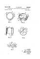
- FIGURE 4 is a perspective view of a stand-oi? member which form one section of the base assembly of the present invention
- FIGURE 5 is a plan view of the stand-elf member
- FIGURE 6 is a bottom view of the base member taken along line 6'-6 of FIGURE 2 and showing in dotted lines the disposition of the resistance element on the opposite surface thereof;
- FIGURE 7 is a partial elevation view illustrating the assembled positions of the base member and the associated stand-off member
- FIGURE 8 is a cross-sectional elevation view of the housing structure illustrating the tabs extending from the open end thereof before being bent over;
- FIGURE 9 is a view taken from the bottom of the device as shown in FIGURE 2 illustrating the engagement of the housing tabs with the grooves formed in the base assembly.
- FIG- URES l3 a variable resistance device, which, in the illustrated embodiment, is a rotary potentiometer.
- This embodiment of the invention employs a generally cylindrical or cup-shaped housing 10 which is substantially closed across one end 11 and substantially open at the other end and enclosing a chamber 12 therein.
- the housing 1 may be formed of any suitable metallic material such as stainless steel, nickel, silver, or aluminum which may be drawn or pressed into the shape shown, or may be formed of a suitable plastic material molded into the desired shape.
- an electrically conductive movable contact member 16 is mounted in the chamber 12 for movement in a predetermined path.
- the electrically conductive contact member or wiper 16 comprises a one-piece sheet metal stamping or disc fabricated of a precious metal alloy and attached securely on a rotor member or body 17 mounted for rotational movement within the cavity 12.
- the rotor body 17 may be fabricated of a non-conducting material, such as molded epoxy resin, and includes an upper cylindrical portion or extension 21 projecting from the larger, lower cylindrical body 17.
- the upper surface 22 of the rotor 17 is horizontal and disposed substantially parallel to end wall 11.
- the lower section of the rotor 17 is provided with a cylindrical shaped cavity 18 defined by a ring-like flange or spacer 19.
- the cavity 18 is adapted to receive the electrical contact element or disc 16 which may be suitably attached to the rotor in a conventional manner, such as by staking.
- a pair of resilient conductive arms or fingers 16a and 16b extend from the disc 16 and make contact with a resistance element and collector member.
- the resilient fingers 16a and 1612 are bent outwardly from the disc 16 and provide a spring bias resisting any force applied against them in the direction of the disc.
- the cylindrical extension 21 of the rotor body extends through a bearing 26 formed in the substantially closed end 1.1 of the housing.
- the bearing 26 supports the extension 21 axially with respect to the housing and the extension 21 provides means for adjusting or moving the rotor 17 and its electrical contact member 16 within the housing.
- a slot 27 is provided in the upper cylindrical section 21 for rotation of the rotor by means of a screwdriver or similar tool.
- the rotor 17 may be rotated by any other means, such as by means of a threaded drive screw journaled through a side wall of the housing and engaging gear teeth formed on the rotor 17.
- Such an arrangement is disclosed in the Habereder Patent No.
- a resilient O ring is mounted between the inner surface of the end wall 11 and the upper surface 22 formed on the rotor 17.
- the O ring has the dual function of sealing the potentiometer interior from contamination and providing a downward or biasing force on the rotor in the direction of the open end of the housing to force the ring or spacer 19 of the rotor against the upper surface of the base assembly as will be explained hereinafter.
- a base assembly is provided which is mounted through the open end of the housing and supports an electrical resistance element 31 in juxtaposed relation with the conductive fingers or contact of the movable contact mern-' ber so that the resistance element is traversed by the movable contact member or wiper during movement or rotation thereof along its path.
- the base assembly comprises a base member or water 32 of non-conductive material, such as a plastic material or ceramic material, which is formed in a size and shape permitting it to be inserted through the open end of the housing.
- the base member 32 supports the resistance element 31 which, in the disclosed embodiment of the invention is in the form of a thin arcuate strip and may comprise any suitable resistance material, such as the type commonly referred to as cerrnet material or conductive plastic material, or any other suitable resitsance material.
- Means are provided for connecting the contact member or disc 16 to a source of electrical potential.
- this comprises the collector disc 33 mounted on the base member and in contact with fingers 16b extending from the contact member 16.
- the collector 33 may typically comprise a thin disc of sheet metal fabricated of platinum or silver alloy or the like.
- Three terminals designated by the reference numeral 34 are provided to connect the resistance element 31 and the collector disc 33 to a source of electrical power or into an external electrical circuit in which the variable resistance device is to be employed.
- the ring 19 rests on the surface of the base member 32 and serves to space the conductive contact disc 16 a predetermined distance above the surface of the resistance element 31 and the collector 33.
- the spring force of the associated fingers 16a and 16b impart a biasing force against the resistance element 31 and the collector 33 making exceedingly good contact therewith.
- the force of the O ring 28 continually biases the rotor against the surface of the base assembly.
- the base member 32 has a slot 35 molded or otherwise formed therein which performs several functions.
- the slot 35 supports or locates the wafer 32 during the deposition process or molding process when the resistance element 31 and collector disc 33 are formed on the opposite surface of the base member.
- the slot 35 serves to locate precisely the position of the arcuate resistance element 31 and, by properly orienting this slot during assembly of the base member 32 within the housing 11, a precise orientation of the arcuate resistance element 31 may be obtained.
- resistance element 31 is shown in one position on the surface of the wafer 32, it should be understood that the position or orientation of the element 31 and the configuration thereof may be at any location on the surface of the wafer 32 and still be disposed at a precisely known location with respect to the slot 35.
- the base assembly includes a stand-off member 36 which is shown in FIG. 4.
- the stand-off 36 may be fabricated of any suitable nonconductive material, such as a molded phenolic plastic, and is generally cylindrical in shape with an upper cylindrical section 37 adapted to fit within the cavity 12 of the housing and a lower cylindrical section 38 of slightly larger diameter, which does not fit within the cavity of the housing.
- the stand-oft member may be of a suitable shape, such as rectangular, or other shape corresponding to the shape of the housing.
- the'stand-ofif member 36 is provided with a plurality of upwardly extending bars 39 the upper surface of which contacts the lower surface or bottom 40 (see FIGURE 7) of the non-conductive base member 32.
- Two of the supporting bars 39 are provided with rounded upwardly protruding shoulders 41 adapted to fit within the slot 35 formed in the lower surface of the base member 32.
- the shoulders 41 engage the base member and prevent rotatioin of the stand-off member 36 with respect to the base member.
- the shoulders 41 engaging with slot 35 also precisely locates the position of the stand-off member with respect to the slot 35 formed in the base member. Because the slot 35 is precisely located with respect to the resistance element, the shoulders also locate the stand-off member with respect to the orientation of the resistance element on the surface of the base member.
- Stop means are provided in the housing to interrupt or stop movement of the contact member at a predetermined position along its path.
- the stop means comprises an indented portion 45 formed in upper surface of the housing or in the closed end 11 of the housing.
- the indentation 45 protrudes well into the cavity in the housing and the opposite edges 45a and 45b of the indentation form a stop against which a lug 46, protruding from the surface 22 of the rotor, engages during movement or rotation of the rotor 17 in either direction.
- the purpose of the stop means is to prevent disengagement of the wiper fingers 24 from the resistance element 31, as the fingers 24 approach the end sections or termination sections 31a and 31b (as indicated in dotted lines in FIGURE 6), of the resistance element.
- Means associated with the housing 10 and base assembly are provided to precisely position the electrical resistance element 31 with respect to the contact member 16 so that the extending fingers 16a of the rotatable contact member are stopped at the limits of rotational excursion of the contact member in a position so that they contact with the end portions 31a and 31b of the resistance element.
- a plurality of tabs 51, 52 and 53 (see FIGURES 8 and 9) extending downwardly from the open end of the housing 10.
- a plurality of mating grooves 54, 55 and 56 (best seen in FIGURES 5 and 9) are also formed in the stand-cit member 36.
- At least one pair of grooves 55 and 56 in the base assembly, or in the stand-off member 36, and at least one pair of tabs 52 and 53, extending from the housing, are positioned a predetermined distance apart differing from the distance apart bet-ween the other of said grooves and tabs so that the respective pairs of grooves and tabs may only be engaged when the base assembly is arranged in a predetermined position with respect to the housing member 11 and its associated stop means or indentation 45.
- grooves 55 and 56 are spaced apart a distance less than the distance between grooves 54 and 55 or between grooves 54 and 56.
- tabs 52 and 53 are spaced apart a similar distance less than the space between the tabs 51 and 52 or between tabs 51 and 53.
- the relative positions of the tabs and the grooves makes it essential that the base assembly be positioned in only one precise position within the housing before the tabs will mate or correspond with the respective grooves formed in the stand-off 36 of the base assembly. After the stand-off member and the base assembly associated therewith have been rotationally oriented with respect to the tabs, the tabs are bent over within the grooves to support the base assembly within the cavity of the housing.
- the base assembly including the base member 32 and the stand-off 36, is of sufficient Width that the tabs 51 engage the stand-off 36 to force the base assembly into snug engagement with the rotor 17 and the O ring 27.
- the open space, surrounding the terminals 34 within the confines of the stand-oh and the bottom 40 of the base member 32 is preferably filled with an epoxy material 58 which also flows into the spaces 59 (best seen in FIGURE 7) formed between the bars 39 of the stand-off and the bottom 40 of the base member 32.
- the epoxy or other suitable sealing material seals this end of the device against contamination from external sources and also helps support the terminals 34 within the housing.
- a variable resistance device comprising:
- cup-shaped housing open at one end and having an end wall across the other end, said housing substantially enclosing a chamber communicating with the open end of said housing;
- a rotor body mounted in said chamber for rotation therein, said rotor body supporting an electrically conductive rotatable contact member for rotation about an a-rcuate path, a lug extending from said rotor and so constructed and arranged as to engage said depression in said end wall of said housing and stop rotation of said rotor in either direction;
- a non-conductive base member adapted to be mounted in said chamber through said open end thereof, said base member having a grooved section on one side thereof and an 'arcuate shaped electrical resistance element supported on the opposite side thereof, said electrical resistance element being adapted to be supported on said base member in juxtaposed relation with respect to said movable contact member so that said rotatable contact member traverses said resistance element during rotation of said contact member around its arcuate path, said resistance element including end terminations electrically connected to opposite ends thereof;
- a stand-off member of electrical insulating material ineluding a pair of lugs extending from the periphery thereof and adapted to fit within said slot in said base member and orient said stand-off member with respect to said base member, said stand-off member being provided with a cylindrical shaped flange which encounters and supports the open end of said hous- 8;
- terminal means for connecting said end terminations of said resistance element and said electrically conductive rotatable contact to a source of electrical potential
Description
R. E. MISHLER 3,387,247
HOUSING AND BASE CONSTRUCTION FOR VARIABLE RESISTANCE DEVICE June 4, 1968 2 Sheets-Sheet 1 Filed Feb. 28, 1966 FIG. I
FIG. 3
INVENTOR. RALPH E. MISHLER ATTORNEY R. E. MISHLER June 4, 1968 HOUSING AND BASE CONSTRUCTION FOR VARIABLE RESISTANCE DEVICE Filed Feb. 28, 1966 2 Sheets-Sheet 2 FIG. 5
Illlllilllllilflfllll.
FIG. 6
FIG; 8
INVENTOR. FIG. 7 RALPH E. MISHLER ATTORNEY United States Patent 3,ss7,247 HOUSING AND BASE (IONSTFIUCTIDN FUR VARIABLE RESISTANCE DEVICE Ralph E. Mishler, Battle Creek, Mich, assignor to Beckman Instruments, Inc, a corporation of California Filed Feb. 28, 1966, Ser. No. 530,574 1 (Ilaim. (Cl. 338--162) ABSTRACT OF THE DISCLOSURE A fool-proof construction for a variable resistance device having a stop means built into the housing thereof for limiting excursion of a Wiper contact adapted to traverse a resistance element mounted within the cavity of the housing. The housing includes a plurality of tabs so arranged and spaced as to mate with grooves formed in the base assembly supporting the resistance element thereby assuring that the housing and base assembly are assembled in a predetermined position with the resistance element properly oriented with respect to the limits of excursion of the wiper.
This invention relates to variable electrical resistance devices and more particularly to such devices commonly known as otentiometers and rheostats.
Potentiometers and rheostats are employed in electrical circuitry to permit adjustment of the voltage and resistance values for a particular circuit. These members generally include a housing which supports a resistance element, having appropriate terminals for connection with the external electrical circuit, and an electrically conductive contact or wiper element which may be moved or adjusted to make the appropriate voltage or resistance changes.
The trend toward miniaturization and weight reduction has created a demand for small variable resistance devices which may be employed in computors, telemetry systems, missiles and in various type of commercial appliances. As the ize and weight of variable resistance devices decrease, it has been found necessary to simplify the design and construction of their components and to minimize the number of parts required to perform the functions of the device.
While the present invention is not limited to a particular housing shape, it is particularly applicable to those variable resistance devices employing a resistance element of arcuate or semicircular shape with which the housing is usually made cylindrical. With such a configuration, the movable electrical contact member or wiper traverses the electrical resistance element over an arcuate path which may be less than 360 of electrical continuity travel. It is sometimes a requirement of such devices that the wiper not break electrical contact with the resistance element or that the wiper or contact member be stopped during its rotational excursion when it encounters an electrical termination pad connecting the end of the electrical contact element with the terminal member through which the device is connected into the external electrical circuitry. Therefore, a stop mechanism is sometimes built into the apparatus as a part of the housing which stops the movement of the contact member at a predetermined point during its excursion along the resistance path. When the stop member is rigidly attached or formed as an integral part of the housing, it is necessary to assemble the resistance element so that it and its associated end terminations are precisely located with respect to the path of wiper travel and the particular points at which wiper travel is stopped. Unless means are built into the respective components of such a device, considerable 3,337,247 Patented June 4, 1968 time and expense may be entailed in manually or electrically positioning such parts during assembly of the device.
Accordingly, it is an object of the invention to provide a variable resistance device having an improved structure which during assembly thereof automatically orients the resistance element and its end terminations with respect to the path of electrical contact travel and the limits of its excursion.
Further objects and advantages of the invention will become apparent as the following description proceeds, and the features of novelty which characterize the invention will be pointed out with particularity in the claim annexed to and forming a part of this specification.
For a better understanding of the invention, reference may be had to the accompanying drawin s, in which:
FIGURE 1 is a top view of the variable resistance device of the present invention;
FIGURE 2 is a cross-sectional view of the variable resistance device of FIGURE 1 taken along line 2--2:
FIGURE 3 is a cross-sectional view of the variable resistance device taken along line 3-3 of FIGURE 2;
FIGURE 4 is a perspective view of a stand-oi? member which form one section of the base assembly of the present invention;
FIGURE 5 is a plan view of the stand-elf member;
FIGURE 6 is a bottom view of the base member taken along line 6'-6 of FIGURE 2 and showing in dotted lines the disposition of the resistance element on the opposite surface thereof;
FIGURE 7 is a partial elevation view illustrating the assembled positions of the base member and the associated stand-off member;
FIGURE 8 is a cross-sectional elevation view of the housing structure illustrating the tabs extending from the open end thereof before being bent over; and
FIGURE 9 is a view taken from the bottom of the device as shown in FIGURE 2 illustrating the engagement of the housing tabs with the grooves formed in the base assembly.
Referring now to the drawings, there is shown in FIG- URES l3 a variable resistance device, which, in the illustrated embodiment, is a rotary potentiometer. This embodiment of the invention employs a generally cylindrical or cup-shaped housing 10 which is substantially closed across one end 11 and substantially open at the other end and enclosing a chamber 12 therein. The housing 1 may be formed of any suitable metallic material such as stainless steel, nickel, silver, or aluminum which may be drawn or pressed into the shape shown, or may be formed of a suitable plastic material molded into the desired shape.
An electrically conductive movable contact member 16 is mounted in the chamber 12 for movement in a predetermined path. In the embodiment illustrated in FIG- URE 2, the electrically conductive contact member or wiper 16 comprises a one-piece sheet metal stamping or disc fabricated of a precious metal alloy and attached securely on a rotor member or body 17 mounted for rotational movement within the cavity 12. The rotor body 17 may be fabricated of a non-conducting material, such as molded epoxy resin, and includes an upper cylindrical portion or extension 21 projecting from the larger, lower cylindrical body 17. The upper surface 22 of the rotor 17 is horizontal and disposed substantially parallel to end wall 11. The lower section of the rotor 17 is provided with a cylindrical shaped cavity 18 defined by a ring-like flange or spacer 19. The cavity 18 is adapted to receive the electrical contact element or disc 16 which may be suitably attached to the rotor in a conventional manner, such as by staking.
In the embodiment shown, a pair of resilient conductive arms or fingers 16a and 16b extend from the disc 16 and make contact with a resistance element and collector member. The resilient fingers 16a and 1612 are bent outwardly from the disc 16 and provide a spring bias resisting any force applied against them in the direction of the disc.
As may be seen in FIGURE 2, the cylindrical extension 21 of the rotor body extends through a bearing 26 formed in the substantially closed end 1.1 of the housing. The bearing 26 supports the extension 21 axially with respect to the housing and the extension 21 provides means for adjusting or moving the rotor 17 and its electrical contact member 16 within the housing. For this purpose a slot 27 is provided in the upper cylindrical section 21 for rotation of the rotor by means of a screwdriver or similar tool. It should be understood, that the rotor 17 may be rotated by any other means, such as by means of a threaded drive screw journaled through a side wall of the housing and engaging gear teeth formed on the rotor 17. Such an arrangement is disclosed in the Habereder Patent No. 3,099,810 also assigned to the same assignce as the present invention. In a drive screw actuated arrangement, it would not be essential to have the extension 21 protruding through the end wall of the housing and other means could be employed for rotatably supporting the rotor.
As may be seen in FIG. 2, a resilient O ring is mounted between the inner surface of the end wall 11 and the upper surface 22 formed on the rotor 17. The O ring has the dual function of sealing the potentiometer interior from contamination and providing a downward or biasing force on the rotor in the direction of the open end of the housing to force the ring or spacer 19 of the rotor against the upper surface of the base assembly as will be explained hereinafter.
A base assembly is provided which is mounted through the open end of the housing and supports an electrical resistance element 31 in juxtaposed relation with the conductive fingers or contact of the movable contact mern-' ber so that the resistance element is traversed by the movable contact member or wiper during movement or rotation thereof along its path. In the described embodiment of the invention, the base assembly comprises a base member or water 32 of non-conductive material, such as a plastic material or ceramic material, which is formed in a size and shape permitting it to be inserted through the open end of the housing. The base member 32 supports the resistance element 31 which, in the disclosed embodiment of the invention is in the form of a thin arcuate strip and may comprise any suitable resistance material, such as the type commonly referred to as cerrnet material or conductive plastic material, or any other suitable resitsance material. Means are provided for connecting the contact member or disc 16 to a source of electrical potential. In the disclosed embodiment this comprises the collector disc 33 mounted on the base member and in contact with fingers 16b extending from the contact member 16. The collector 33 may typically comprise a thin disc of sheet metal fabricated of platinum or silver alloy or the like. Three terminals designated by the reference numeral 34 are provided to connect the resistance element 31 and the collector disc 33 to a source of electrical power or into an external electrical circuit in which the variable resistance device is to be employed.
As will be seen in FIGURE 2, the ring 19 rests on the surface of the base member 32 and serves to space the conductive contact disc 16 a predetermined distance above the surface of the resistance element 31 and the collector 33. The spring force of the associated fingers 16a and 16b impart a biasing force against the resistance element 31 and the collector 33 making exceedingly good contact therewith. The force of the O ring 28 continually biases the rotor against the surface of the base assembly.
As may best be seen in FIGURES 2 and 6, .the base member 32 has a slot 35 molded or otherwise formed therein which performs several functions. In the manufacturing process the slot 35 supports or locates the wafer 32 during the deposition process or molding process when the resistance element 31 and collector disc 33 are formed on the opposite surface of the base member. Thus, the slot 35 serves to locate precisely the position of the arcuate resistance element 31 and, by properly orienting this slot during assembly of the base member 32 within the housing 11, a precise orientation of the arcuate resistance element 31 may be obtained. While the resistance element 31 is shown in one position on the surface of the wafer 32, it should be understood that the position or orientation of the element 31 and the configuration thereof may be at any location on the surface of the wafer 32 and still be disposed at a precisely known location with respect to the slot 35.
In addition to the base element 32 the base assembly includes a stand-off member 36 which is shown in FIG. 4. The stand-off 36 may be fabricated of any suitable nonconductive material, such as a molded phenolic plastic, and is generally cylindrical in shape with an upper cylindrical section 37 adapted to fit within the cavity 12 of the housing and a lower cylindrical section 38 of slightly larger diameter, which does not fit within the cavity of the housing. Obviously, if the housing is not cylindrical or is not provided with a cylindrical cavity, the stand-oft member may be of a suitable shape, such as rectangular, or other shape corresponding to the shape of the housing. In the embodiment shown, the'stand-ofif member 36 is provided with a plurality of upwardly extending bars 39 the upper surface of which contacts the lower surface or bottom 40 (see FIGURE 7) of the non-conductive base member 32. Two of the supporting bars 39 are provided with rounded upwardly protruding shoulders 41 adapted to fit within the slot 35 formed in the lower surface of the base member 32. The shoulders 41 engage the base member and prevent rotatioin of the stand-off member 36 with respect to the base member. The shoulders 41 engaging with slot 35, also precisely locates the position of the stand-off member with respect to the slot 35 formed in the base member. Because the slot 35 is precisely located with respect to the resistance element, the shoulders also locate the stand-off member with respect to the orientation of the resistance element on the surface of the base member.
Stop means are provided in the housing to interrupt or stop movement of the contact member at a predetermined position along its path. As may be seen in FIG- URES 1, 2 and 3, the stop means comprises an indented portion 45 formed in upper surface of the housing or in the closed end 11 of the housing. The indentation 45 protrudes well into the cavity in the housing and the opposite edges 45a and 45b of the indentation form a stop against which a lug 46, protruding from the surface 22 of the rotor, engages during movement or rotation of the rotor 17 in either direction. As previously explained, the purpose of the stop means is to prevent disengagement of the wiper fingers 24 from the resistance element 31, as the fingers 24 approach the end sections or termination sections 31a and 31b (as indicated in dotted lines in FIGURE 6), of the resistance element.
Means associated with the housing 10 and base assembly are provided to precisely position the electrical resistance element 31 with respect to the contact member 16 so that the extending fingers 16a of the rotatable contact member are stopped at the limits of rotational excursion of the contact member in a position so that they contact with the end portions 31a and 31b of the resistance element.
In order to precisely locate the base assembly, and the associated electrical resistance element, with respect to the stop means 45, there are provided a plurality of tabs 51, 52 and 53 (see FIGURES 8 and 9) extending downwardly from the open end of the housing 10. A plurality of mating grooves 54, 55 and 56 (best seen in FIGURES 5 and 9) are also formed in the stand-cit member 36. As will be noted in FIGURES 5 and 9 at least one pair of grooves 55 and 56 in the base assembly, or in the stand-off member 36, and at least one pair of tabs 52 and 53, extending from the housing, are positioned a predetermined distance apart differing from the distance apart bet-ween the other of said grooves and tabs so that the respective pairs of grooves and tabs may only be engaged when the base assembly is arranged in a predetermined position with respect to the housing member 11 and its associated stop means or indentation 45. Thus, as may be seen in FIGURE 5, grooves 55 and 56 are spaced apart a distance less than the distance between grooves 54 and 55 or between grooves 54 and 56. Similarly tabs 52 and 53 are spaced apart a similar distance less than the space between the tabs 51 and 52 or between tabs 51 and 53. Thus, as may be seen in FIGURE 9, the relative positions of the tabs and the grooves makes it essential that the base assembly be positioned in only one precise position within the housing before the tabs will mate or correspond with the respective grooves formed in the stand-off 36 of the base assembly. After the stand-off member and the base assembly associated therewith have been rotationally oriented with respect to the tabs, the tabs are bent over within the grooves to support the base assembly within the cavity of the housing.
As may be seen in the drawings, the base assembly, including the base member 32 and the stand-off 36, is of sufficient Width that the tabs 51 engage the stand-off 36 to force the base assembly into snug engagement with the rotor 17 and the O ring 27. In order to further accurately locate the resistance element 31 within the housing, it may be desirable to make one of the grooves,
such as groove 54, as may be seen in FIGURE 9, only slightly large-r than its associated tab 51. This, then makes it absolutely essential that the one tab fit precisely Within its respective groove and thereby locate the remaining tabs, such as tabs 52 and 53, centrally within their associated grooves.
After the tabs have been bent over against the base assembly and, thereby, securely retain the base assembly within the housing, the open space, surrounding the terminals 34 within the confines of the stand-oh and the bottom 40 of the base member 32 is preferably filled with an epoxy material 58 which also flows into the spaces 59 (best seen in FIGURE 7) formed between the bars 39 of the stand-off and the bottom 40 of the base member 32. The epoxy or other suitable sealing material seals this end of the device against contamination from external sources and also helps support the terminals 34 within the housing.
While, in accordance with the patent statutes, there has been described what at present is considered to be the preferred embodiment of the present invention, it will be obvious to those skilled'in the art that various changes and modifications may be made therein without departing from the invention and it is, therefore, the aim of the appended claim to cover all such changes and modifications as fall within the true spirit and scope of the invention.
What is claimed is:
1. A variable resistance device comprising:
a cup-shaped housing open at one end and having an end wall across the other end, said housing substantially enclosing a chamber communicating with the open end of said housing;
a depression formed in said end wall of said chamber and protruding into said chamber;
a rotor body mounted in said chamber for rotation therein, said rotor body supporting an electrically conductive rotatable contact member for rotation about an a-rcuate path, a lug extending from said rotor and so constructed and arranged as to engage said depression in said end wall of said housing and stop rotation of said rotor in either direction;
adjustment means for rotating said rotor, said means being adjustable externally of said housing;
a non-conductive base member adapted to be mounted in said chamber through said open end thereof, said base member having a grooved section on one side thereof and an 'arcuate shaped electrical resistance element supported on the opposite side thereof, said electrical resistance element being adapted to be supported on said base member in juxtaposed relation with respect to said movable contact member so that said rotatable contact member traverses said resistance element during rotation of said contact member around its arcuate path, said resistance element including end terminations electrically connected to opposite ends thereof;
a stand-off member of electrical insulating material ineluding a pair of lugs extending from the periphery thereof and adapted to fit within said slot in said base member and orient said stand-off member with respect to said base member, said stand-off member being provided with a cylindrical shaped flange which encounters and supports the open end of said hous- 8;
terminal means for connecting said end terminations of said resistance element and said electrically conductive rotatable contact to a source of electrical potential;
means associated with said housing and said base and stand-off members for supporting and positioning said base member within said housing, said means comprising:
a plurality of tabs extending from said housing adjacent the open end thereof, said tabs being adapted to fold over and support said base and stand-off members within said housing, a plurality of grooves formed in said stand-off member, each of said grooves being so constructed and arranged as to receive one of said tabs of said housing;
at least one pair of said grooves in said standoff member and at least one pair of said tabs extending from said housing being positioned a pre-determined distance apart differing from the distance apart between the other of said grooves and tabs so that said pair of grooves and said pair of tabs may only be engaged when said base assembly and said stand-off member are arranged in a pre-determined position within said housing with said resistance element on said base member so oriented with respect to the path of said contact member that said lug of said rotor engages said depression in said housing to stop said contact member during the course of its excursion in either direction as said contact member encounters said end terminations of said resistance element.
References Cited UNITED STATES PATENTS 1,971,617 8/1934 Meuer 338184 X 1,997,258 4/1935 Krieger 338184 X 2,358,991 9/1944 Miller 338--184 X FOREIGN PATENTS 868,905 5/1961 Great Britain. 1,124,131 2/1962 Germany.
ROBERT K. SCHAEFER, Primary Examiner.
H. HOHAUSER, Assistant Examiner.
Priority Applications (3)
| Application Number | Priority Date | Filing Date | Title |
|---|---|---|---|
| US530574A US3387247A (en) | 1966-02-28 | 1966-02-28 | Housing and base construction for variable resistance device |
| GB4359/67A GB1113084A (en) | 1966-02-28 | 1967-01-30 | Variable resistance device |
| DE19671615712 DE1615712A1 (en) | 1966-02-28 | 1967-02-24 | Changeable resistance |
Applications Claiming Priority (1)
| Application Number | Priority Date | Filing Date | Title |
|---|---|---|---|
| US530574A US3387247A (en) | 1966-02-28 | 1966-02-28 | Housing and base construction for variable resistance device |
Publications (1)
| Publication Number | Publication Date |
|---|---|
| US3387247A true US3387247A (en) | 1968-06-04 |
Family
ID=24114138
Family Applications (1)
| Application Number | Title | Priority Date | Filing Date |
|---|---|---|---|
| US530574A Expired - Lifetime US3387247A (en) | 1966-02-28 | 1966-02-28 | Housing and base construction for variable resistance device |
Country Status (3)
| Country | Link |
|---|---|
| US (1) | US3387247A (en) |
| DE (1) | DE1615712A1 (en) |
| GB (1) | GB1113084A (en) |
Cited By (7)
| Publication number | Priority date | Publication date | Assignee | Title |
|---|---|---|---|---|
| US3518604A (en) * | 1968-02-12 | 1970-06-30 | Cts Corp | Electrical component |
| US3537056A (en) * | 1967-12-26 | 1970-10-27 | Cts Corp | Miniature variable resistance control |
| US3735326A (en) * | 1971-10-26 | 1973-05-22 | Electrosil Ltd | Adjustable electrical devices with leadscrew and sealing means |
| US3815225A (en) * | 1971-10-26 | 1974-06-11 | Electrosil Ltd | Method of making an adjustable electrical component |
| US4121188A (en) * | 1975-12-19 | 1978-10-17 | North American Philips Corporation | Closed frame single turn potentiometer with helical coil spring wiper adjustable through substrate |
| US4295119A (en) * | 1979-03-12 | 1981-10-13 | Alps Electric Co., Ltd. | Rotary variable resistor |
| US4492950A (en) * | 1983-03-01 | 1985-01-08 | American Plasticraft Company | Variable resistance assembly with improved contactor knob |
Families Citing this family (1)
| Publication number | Priority date | Publication date | Assignee | Title |
|---|---|---|---|---|
| DE19533991B4 (en) * | 1995-09-14 | 2009-07-02 | Knorr-Bremse Systeme für Nutzfahrzeuge GmbH | potentiometer |
Citations (5)
| Publication number | Priority date | Publication date | Assignee | Title |
|---|---|---|---|---|
| US1971617A (en) * | 1932-01-23 | 1934-08-28 | Cutler Hammer Inc | Rheostat |
| US1997258A (en) * | 1934-11-19 | 1935-04-09 | Cutler Hammer Inc | Rheostat for control of relatively low voltage circuits |
| US2358991A (en) * | 1942-03-02 | 1944-09-26 | Morgan Crucible Co | Variable electric resistance |
| GB868905A (en) * | 1959-11-17 | 1961-05-25 | Int Resistance Co | Variable resistor with vernier control |
| DE1124131B (en) * | 1956-02-16 | 1962-02-22 | Plessey Co Ltd | Rotation resistance |
-
1966
- 1966-02-28 US US530574A patent/US3387247A/en not_active Expired - Lifetime
-
1967
- 1967-01-30 GB GB4359/67A patent/GB1113084A/en not_active Expired
- 1967-02-24 DE DE19671615712 patent/DE1615712A1/en active Pending
Patent Citations (5)
| Publication number | Priority date | Publication date | Assignee | Title |
|---|---|---|---|---|
| US1971617A (en) * | 1932-01-23 | 1934-08-28 | Cutler Hammer Inc | Rheostat |
| US1997258A (en) * | 1934-11-19 | 1935-04-09 | Cutler Hammer Inc | Rheostat for control of relatively low voltage circuits |
| US2358991A (en) * | 1942-03-02 | 1944-09-26 | Morgan Crucible Co | Variable electric resistance |
| DE1124131B (en) * | 1956-02-16 | 1962-02-22 | Plessey Co Ltd | Rotation resistance |
| GB868905A (en) * | 1959-11-17 | 1961-05-25 | Int Resistance Co | Variable resistor with vernier control |
Cited By (7)
| Publication number | Priority date | Publication date | Assignee | Title |
|---|---|---|---|---|
| US3537056A (en) * | 1967-12-26 | 1970-10-27 | Cts Corp | Miniature variable resistance control |
| US3518604A (en) * | 1968-02-12 | 1970-06-30 | Cts Corp | Electrical component |
| US3735326A (en) * | 1971-10-26 | 1973-05-22 | Electrosil Ltd | Adjustable electrical devices with leadscrew and sealing means |
| US3815225A (en) * | 1971-10-26 | 1974-06-11 | Electrosil Ltd | Method of making an adjustable electrical component |
| US4121188A (en) * | 1975-12-19 | 1978-10-17 | North American Philips Corporation | Closed frame single turn potentiometer with helical coil spring wiper adjustable through substrate |
| US4295119A (en) * | 1979-03-12 | 1981-10-13 | Alps Electric Co., Ltd. | Rotary variable resistor |
| US4492950A (en) * | 1983-03-01 | 1985-01-08 | American Plasticraft Company | Variable resistance assembly with improved contactor knob |
Also Published As
| Publication number | Publication date |
|---|---|
| GB1113084A (en) | 1968-05-08 |
| DE1615712A1 (en) | 1970-05-14 |
Similar Documents
| Publication | Publication Date | Title |
|---|---|---|
| US2880293A (en) | Adjustable potentiometer | |
| US3387247A (en) | Housing and base construction for variable resistance device | |
| US3970986A (en) | Thick film rotary switch | |
| US2877317A (en) | Switching mechanism for timer | |
| US4555686A (en) | Snap-acting thermostatic switch assembly | |
| US3657688A (en) | Compact variable resistor with rotary resistance element | |
| US4184140A (en) | Two-piece trimming potentiometer | |
| US2201882A (en) | Electric switch | |
| US2551989A (en) | Potentiometric device | |
| US3377606A (en) | Potentiometer apparatus | |
| US3115614A (en) | Miniature potentiometer with stop mechanism | |
| US3629780A (en) | Variable resistance control and switch with common operating member | |
| US3378803A (en) | Variable resistance device | |
| US3124778A (en) | youngbeck | |
| US3324261A (en) | Snap switch means | |
| KR890002534B1 (en) | Rotary operation type miniaturized electronic component | |
| US2766359A (en) | Variable resistance device | |
| US3346708A (en) | Rotary switch with roller detent apparatus directly biasing contact structure into open and closed positions | |
| US3533043A (en) | Adjustable electronic component | |
| US2873340A (en) | Variable resistor | |
| US3301971A (en) | Electric switch with improved disk and contact structure | |
| US2953667A (en) | Cam-actuated switch assembly for a repeating interval timer or the like | |
| US3219960A (en) | Variable resistance device | |
| US3309471A (en) | Rotary switch contact structure with improved washer fastening means | |
| US3413590A (en) | Potentiometer |
Legal Events
| Date | Code | Title | Description |
|---|---|---|---|
| AS | Assignment |
Owner name: BECKMAN INDUSTRIAL CORPORATION A CORP OF DE Free format text: ASSIGNMENT OF ASSIGNORS INTEREST.;ASSIGNOR:EMERSON ELECTRIC CO., A CORP OF MO;REEL/FRAME:004328/0659 Effective date: 19840425 Owner name: EMERSON ELECTRIC CO., A MO CORP. Free format text: ASSIGNMENT OF ASSIGNORS INTEREST.;ASSIGNOR:BECKMAN INSTRUMENTS, INC.;REEL/FRAME:004319/0695 Effective date: 19840301 |