US3401465A - Means for cooling solid particulate materials with fluids - Google Patents
Means for cooling solid particulate materials with fluids Download PDFInfo
- Publication number
- US3401465A US3401465A US604390A US60439066A US3401465A US 3401465 A US3401465 A US 3401465A US 604390 A US604390 A US 604390A US 60439066 A US60439066 A US 60439066A US 3401465 A US3401465 A US 3401465A
- Authority
- US
- United States
- Prior art keywords
- cooling
- chamber
- particulate material
- level control
- solid particulate
- Prior art date
- Legal status (The legal status is an assumption and is not a legal conclusion. Google has not performed a legal analysis and makes no representation as to the accuracy of the status listed.)
- Expired - Lifetime
Links
- 238000001816 cooling Methods 0.000 title description 90
- 239000011236 particulate material Substances 0.000 title description 47
- 239000007787 solid Substances 0.000 title description 34
- 239000012530 fluid Substances 0.000 title description 3
- 239000000463 material Substances 0.000 description 33
- 239000007789 gas Substances 0.000 description 30
- 239000002826 coolant Substances 0.000 description 13
- OGIDPMRJRNCKJF-UHFFFAOYSA-N titanium oxide Inorganic materials [Ti]=O OGIDPMRJRNCKJF-UHFFFAOYSA-N 0.000 description 13
- 239000000049 pigment Substances 0.000 description 8
- 238000000034 method Methods 0.000 description 7
- 230000005465 channeling Effects 0.000 description 6
- 230000008569 process Effects 0.000 description 5
- 238000005054 agglomeration Methods 0.000 description 4
- 230000002776 aggregation Effects 0.000 description 4
- 239000002131 composite material Substances 0.000 description 4
- 239000000428 dust Substances 0.000 description 4
- 230000003190 augmentative effect Effects 0.000 description 3
- 239000000112 cooling gas Substances 0.000 description 3
- 230000000694 effects Effects 0.000 description 3
- 238000004519 manufacturing process Methods 0.000 description 3
- 239000011343 solid material Substances 0.000 description 3
- XLYOFNOQVPJJNP-UHFFFAOYSA-N water Substances O XLYOFNOQVPJJNP-UHFFFAOYSA-N 0.000 description 3
- GWEVSGVZZGPLCZ-UHFFFAOYSA-N Titan oxide Chemical compound O=[Ti]=O GWEVSGVZZGPLCZ-UHFFFAOYSA-N 0.000 description 2
- 239000003795 chemical substances by application Substances 0.000 description 2
- 239000012808 vapor phase Substances 0.000 description 2
- 241000239290 Araneae Species 0.000 description 1
- 208000036366 Sensation of pressure Diseases 0.000 description 1
- QAOWNCQODCNURD-UHFFFAOYSA-L Sulfate Chemical compound [O-]S([O-])(=O)=O QAOWNCQODCNURD-UHFFFAOYSA-L 0.000 description 1
- 230000009471 action Effects 0.000 description 1
- 238000013019 agitation Methods 0.000 description 1
- 238000010420 art technique Methods 0.000 description 1
- 230000003139 buffering effect Effects 0.000 description 1
- 238000007599 discharging Methods 0.000 description 1
- -1 for example Substances 0.000 description 1
- 230000006872 improvement Effects 0.000 description 1
- 210000003141 lower extremity Anatomy 0.000 description 1
- 229910052751 metal Inorganic materials 0.000 description 1
- 239000002184 metal Substances 0.000 description 1
- 238000012986 modification Methods 0.000 description 1
- 230000004048 modification Effects 0.000 description 1
- 239000002245 particle Substances 0.000 description 1
- 230000001698 pyrogenic effect Effects 0.000 description 1
- 238000005057 refrigeration Methods 0.000 description 1
- 230000000717 retained effect Effects 0.000 description 1
- 239000000725 suspension Substances 0.000 description 1
- 239000004408 titanium dioxide Substances 0.000 description 1
Images

Classifications
-
- F—MECHANICAL ENGINEERING; LIGHTING; HEATING; WEAPONS; BLASTING
- F28—HEAT EXCHANGE IN GENERAL
- F28C—HEAT-EXCHANGE APPARATUS, NOT PROVIDED FOR IN ANOTHER SUBCLASS, IN WHICH THE HEAT-EXCHANGE MEDIA COME INTO DIRECT CONTACT WITHOUT CHEMICAL INTERACTION
- F28C3/00—Other direct-contact heat-exchange apparatus
- F28C3/10—Other direct-contact heat-exchange apparatus one heat-exchange medium at least being a fluent solid, e.g. a particulate material
- F28C3/12—Other direct-contact heat-exchange apparatus one heat-exchange medium at least being a fluent solid, e.g. a particulate material the heat-exchange medium being a particulate material and a gas, vapour, or liquid
- F28C3/16—Other direct-contact heat-exchange apparatus one heat-exchange medium at least being a fluent solid, e.g. a particulate material the heat-exchange medium being a particulate material and a gas, vapour, or liquid the particulate material forming a bed, e.g. fluidised, on vibratory sieves
-
- B—PERFORMING OPERATIONS; TRANSPORTING
- B01—PHYSICAL OR CHEMICAL PROCESSES OR APPARATUS IN GENERAL
- B01J—CHEMICAL OR PHYSICAL PROCESSES, e.g. CATALYSIS OR COLLOID CHEMISTRY; THEIR RELEVANT APPARATUS
- B01J8/00—Chemical or physical processes in general, conducted in the presence of fluids and solid particles; Apparatus for such processes
- B01J8/08—Chemical or physical processes in general, conducted in the presence of fluids and solid particles; Apparatus for such processes with moving particles
- B01J8/10—Chemical or physical processes in general, conducted in the presence of fluids and solid particles; Apparatus for such processes with moving particles moved by stirrers or by rotary drums or rotary receptacles or endless belts
-
- B—PERFORMING OPERATIONS; TRANSPORTING
- B01—PHYSICAL OR CHEMICAL PROCESSES OR APPARATUS IN GENERAL
- B01J—CHEMICAL OR PHYSICAL PROCESSES, e.g. CATALYSIS OR COLLOID CHEMISTRY; THEIR RELEVANT APPARATUS
- B01J8/00—Chemical or physical processes in general, conducted in the presence of fluids and solid particles; Apparatus for such processes
- B01J8/18—Chemical or physical processes in general, conducted in the presence of fluids and solid particles; Apparatus for such processes with fluidised particles
- B01J8/1836—Heating and cooling the reactor
-
- B—PERFORMING OPERATIONS; TRANSPORTING
- B01—PHYSICAL OR CHEMICAL PROCESSES OR APPARATUS IN GENERAL
- B01J—CHEMICAL OR PHYSICAL PROCESSES, e.g. CATALYSIS OR COLLOID CHEMISTRY; THEIR RELEVANT APPARATUS
- B01J8/00—Chemical or physical processes in general, conducted in the presence of fluids and solid particles; Apparatus for such processes
- B01J8/18—Chemical or physical processes in general, conducted in the presence of fluids and solid particles; Apparatus for such processes with fluidised particles
- B01J8/24—Chemical or physical processes in general, conducted in the presence of fluids and solid particles; Apparatus for such processes with fluidised particles according to "fluidised-bed" technique
- B01J8/38—Chemical or physical processes in general, conducted in the presence of fluids and solid particles; Apparatus for such processes with fluidised particles according to "fluidised-bed" technique with fluidised bed containing a rotatable device or being subject to rotation or to a circulatory movement, i.e. leaving a vessel and subsequently re-entering it
- B01J8/382—Chemical or physical processes in general, conducted in the presence of fluids and solid particles; Apparatus for such processes with fluidised particles according to "fluidised-bed" technique with fluidised bed containing a rotatable device or being subject to rotation or to a circulatory movement, i.e. leaving a vessel and subsequently re-entering it with a rotatable device only
-
- B—PERFORMING OPERATIONS; TRANSPORTING
- B01—PHYSICAL OR CHEMICAL PROCESSES OR APPARATUS IN GENERAL
- B01J—CHEMICAL OR PHYSICAL PROCESSES, e.g. CATALYSIS OR COLLOID CHEMISTRY; THEIR RELEVANT APPARATUS
- B01J8/00—Chemical or physical processes in general, conducted in the presence of fluids and solid particles; Apparatus for such processes
- B01J8/18—Chemical or physical processes in general, conducted in the presence of fluids and solid particles; Apparatus for such processes with fluidised particles
- B01J8/24—Chemical or physical processes in general, conducted in the presence of fluids and solid particles; Apparatus for such processes with fluidised particles according to "fluidised-bed" technique
- B01J8/44—Fluidisation grids
-
- C—CHEMISTRY; METALLURGY
- C01—INORGANIC CHEMISTRY
- C01G—COMPOUNDS CONTAINING METALS NOT COVERED BY SUBCLASSES C01D OR C01F
- C01G23/00—Compounds of titanium
- C01G23/04—Oxides; Hydroxides
- C01G23/047—Titanium dioxide
- C01G23/07—Producing by vapour phase processes, e.g. halide oxidation
- C01G23/075—Evacuation and cooling of the gaseous suspension containing the oxide; Desacidification and elimination of gases occluded in the separated oxide
Definitions
- the present invention relates in general to heat exchangers and more especially to a means for cooling a hot, finely divided particulate material, by fiuidizing the same with a relatively cold gas.
- the invention pertains to a low cost, efiicient means for cooling a solid particulate material, such as for example, titanium dioxide, by feeding the hot particulate material into the top of a cooling chamber in which the hot material is fluidizedby admission of a cold gas into the bottom of the cooling chamber in a direction substantially parallel to the plane of its bottom surface the cold gas flowing upwardly countercurrent to the downwardly moving hot particulate material which is maintains as a relatively dee-p fluidized bed within the cooling chamber by a level control chamber connected to a discharge outlet at the bottom of the cooling chamber whereby highly efficient countercurrent heat exchange is made possible between the cooling gas and the hot particulate material, the eflicacy of heat exchange being augmented by providing agitating means in either or both the cooling chamber and level control chamber to eliminate gas channeling and control agglomeration of the fluidized particulate material.
- a solid particulate material such as for example, titanium dioxide
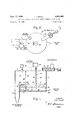
- FIGURES 1 and 2 show an embodiment of this apparatus which comprises, in general, three integrated units identified by the numerals 10, 11 and 12 respectively, the unit 10 being hereinafter referred to as a cooling chamber, the unit 11 as a level control chamber and the unit 12 as a discharge duct.
- the cooling chamber 10 is the unit into which the hot solid particulate material is fed and held temporarily while being cooled.
- the solid particulate material may be a Ti0 material such as calciner discharge, the milled TiO from a steam micronizer or the hot pigmentary TiO issuing from the reaction chamber of a vapor phase process for producing a pyrogenic TiO; material.
- the hot material is adapted to be fed from a supply source into the cooling chamber 10 where it is temporarily retained while being subjected to the cooling action of a cold gas arranged to pass upwardly in counter current flow through the hot material to remove the latent heat therefrom; after which the cooled material is transported to the level control chamber and from thence to the discharge duct 12 as hereinafter described.
- the solid hot material may be fed into the cooling chamber 10 at any point therein, i.e., at the top or bottom thereof but for purposes of illustration the feed means is shown at the top of the chamber 10.
- the feed means is preferably although not necessarily a power operated screw conveyor 13 assembled in a conduit 14 mounted on the top of the cooling chamber 10 to which the hot particulate material is delivered from a supply source not shown.
- the cooling chamber 10 is a substantially vertical vessel or chamber preferably although not necessarily of circular cross section, see FIG. 2, and is divided into an upper cooling zone 15 and bottom plenum chamber 16 by gas distributor means 17 which, as hereinafter described, is designed to feed cold gas from the plenum chamber 16 into the cooling zone 15 of the chamber 10 at sufiicient velocity to fluidize the hot particulate material there- 1n.
- the gas distributor means 17 comprises a circular plate corresponding in diameter to the ID. of the cooling chamber and arranged to be secured therein in a substantially horizontal plane.
- the distributor plate 17 may be a single unit, as shown in FIGURE 3, or may comprise a plurality of separate sections, i.e., fourquadrants, 171, 172, 173 and 174, held together in the form of a single unit 176 as shown in FIGURE 4. Whether in the form of a single unit or a plurality of separate sections the distributor plate is supported in the cooling chamber 10 by a spider 18 or equivalent mechanical device.
- each section of the distributor plate is characterized by a ribbed surface which, as shown especially well in FIG- URE 3, comprises, preferably, a plurality of spaced parallel hollow ridges or corrugations 19 struck up from a sheet metal plate, each corrugation being substantially tooth-shaped in cross section. More particularly each tooth-shaped corrugation 19 comprises one sloping wall 20 and one wall 21 substantially perpendicular to the plane of the plate. Further, each perpendicular wall 21 is provided with a plurality of jet apertures 22 equally spaced there-along with the axis of each jet aperture substantially parallel to the plane of the plate.
- the toothshaped corrugations are identified by the numeral 191
- the cold gas may be air or any other suitable gaseous medium, and is adapted to issue from the jet apertures 22 at a linear velocity such that the solid particulate material in the cooling zone 15 will be fluidized and simultaneously cooled.
- agitating means 24 Operating in conjunction with the cold gas to fluidize and cool the solid particulate material is agitating means 24.
- the use of fluidized beds for cooling solid particulate materials is not in itself new but whenever they have been used they have been found to augment the dust load, to be subject to plugging and gas channeling and to provide relatively ineflicient heat transfer.
- the agitating means 24 comprises a multibladed sweep 25 carried on the lower extremity of a shaft 26 the upper end of which extends through the top of the cooling chamber and is connected to suitable drive means indicated generally at 27.
- the effectiveness of the agitating means depends not only upon its speed of rotation, but also on the depth of the fluidized bed and the location of the agitator therein. For fluidized beds ranging from 4-26 inches in height the speed of rotation of the agitator is relatively slow, i.e., from 8 to 130 r.p.m.
- the location of the multi bladed sweep 25 in the bed is not critical it is preferably located adjacent the bottom of the bed where it serves also to augment discharge of the cooled solid particulate material from the cooling zone into the level control chamber 11.
- the level control chamber 11 comprises one unit of the cooling apparatus and serves to assure countercurrent flow of the particulate material and the cooling gas by buffering the discharge of cooled material from the bottom of the cooling chamber so as to maintain a relatively deep bed in the cooling chamber 10. It has been found that if no level control chamber is used and the particulate material in the cooling chamber is discharged therefrom directly through a bottom port an eflicient countercurrent cooling effect can not be maintained. However by using the level control chamber 11 in conjunction with the cooling chamber 10 to maintain a relatively deep bed of particulate material in the cooling chamber counter current cooling for maximum heat exchange is assured. As shown in FIGURE 2 the level control chamber 11 is positioned on the side of the cooling chamber 10 substantially opposite the feed means 14.
- a divider wall 28 having a connecting passage 281 to the bottom of the cooling chamber separates the level control chamber 11 from the cooling chamber 10.
- the level control chamber 11 consists of an upper zone 29, and air distributor plate 17', which is preferably although not necessarily coextensive with the air distributor plate 17; an air plenum 16' joined to the plenum 16 of the cooling chamber 10 by passage 30 through a divider 31; and an agitator 32 carried on the lower end of a shaft 33 driven by drive means 34.
- the air distributor 17' is identical to air distributor 17 except for overall size; and air at superatmospheric pressure is adapted to issue from its jet apertures 22 to maintain a fluidized bed of particulate material in zone 29 of the level control chamber 11.
- the air plenum 16' which supplies air to the level control chamber 11 by way of the jet apertures 22 of the distributor plate 17 receives air at superatmospheric pres sure through passage 30 from plenum 16.
- the agitator 32 in the level control chamber 11 is adapted to be rotated at relatively slow speeds, i.e., from 8 to r.p.m. to control agglomeration and prevent air channeling.
- one or more air jet booster devices 35 which in the embodiment shown comprises two pipes each having a plurality of small holes in its upper wall.
- the air jets from these pipes are adapted to loosen up and assist the movement of the solid particulate material as it is transferred from the bottom of the cooling chamber 10 into the level control chamber 11 and to this end air under superatmospheric pressure is delivered to the apertured pipes 35 from a source not shown and issues from the holes therein as high velocity air jets.
- the upper end of the discharge duct 12 opens into the level control tower 11 immediately above the distributor plate 17 and is adapted to be closed 01f therefrom by a manually operated gate valve 36 which serves to control the discharge of cooled material from the level control tower 11.
- the solid particulate material to be cooled was, in this case, hot TiO pigmentary material discharged from a micronizer the temperature of the pigment being about 340 F.
- the hot pigmentary TiO was fed at the rate of about 65.3 lb./ min. into the top of a cooling chamber 10 which consisted of a cylindrical tank tflve feet in diameter and about 38 in. high.
- the cooling zone 15 above the air distributor plate 17 was about 32 in. high and the depth of the bed material therein was about 11 in.
- the agitating means which comprised two sweep arms set at 2 in. and 11 in. respectively above the distributor plate was rotated at 8 r.p.m.
- the level control chamber 11 was substantially rectangular in cross section and extended radially from the side of the cooling chamber substantially opposite the material feed means.
- Cold air 40 F.
- the hot pigmentary TiO was thereby fluidized and simultaneously cooled by the upwardly flowing cold gas.
- the relatively slow sweep of the agitator eliminated air channeling in the bed and produced a mild agglomeration of the pigment particles which minimized dust load and augmented heat transfer from the hot pigmentary material to the cold air.
- the velocity of the cold gas entering the level control chamber was the same as in the cooling chamber 10 and contributed some additional cooling effect.
- the agitator 32 was rotated at about 120' r.p.m.
- the heat loss of the pigment in B.t.u./ hr. sq. ft. bed section was 8800 and the temperature of the pigmentary Ti0 discharged from the cooling tower was about 115 F. Pressure drop was 4 inches water gauge.
- EXAMPLE II A second lot of hot pigmentary Ti0 was cooled using the equipment described in Example I but in this run the temperature of the air was 75 F. and it was introduced intothe cooling zone at the rate of 1238 c.f.m. or 91.8 lb./min. standard temperature and pressure. The agitator was rotated at r.p.m. and the pigmentary TiO was fed into the cooling zone at a temperature of 330 F.
- EXAMPLE III Another run was made using the equipment described above but in this case the temperature of the air was 95 F. and it was introduced into the cooling zone at the rate of 1058 c.f.m. or 75.7 lb./min. standard pressure and temperature.
- the initial temperature of the pigment was 330 F. and it was fed into the cooling zone at the rate of 29.3 1b./min. to form a bed 14 inches deep.
- the heat loss of the pigment was 7800 B.t.u./hr. sq. ft. bed section the final temperature of the pigment being 165 F. Dust load was 300 lb. per hour and pressure drop 9.2 inches water gauge.
- the invention is characterized by the novel concept of cooling a hot solid particulate material by simultaneously fluidizing and cooling the material with a cold gas which is introduced into the bottom of a bed of the material through a plurality of jets at substantially right angles to the longitudinal axis of the bed; maintaining a relatively deep bed of fluidized material by discharging the bed material from the bottom of the cooling chamber into a level control chamber so as to assure countercurrent heat exchange; and simultaneously agitating the fluidized bed with a relatively slow moving sweep; and that the combined etfect of the countercurrent heat exchange and mild agitation of the fluidized material is a relatively efficient heat exchange between the hot particulate material and the cold gas together with minimum dust load and absence of plugging, channeling, run-back and high pressure drop.
- Apparatus for cooling a solid particulate material by contact with a gaseous coolant comprising in combination: a cooling chamber having an inlet at its upper end and an outlet at its lower end, a level control chamber connected to the outlet of said cooling chamber, distributor means constructed and arranged to divide said cooling chamber into a cooling zone and a plenum chamber, feed means constructed and arranged at the inlet of said cooling chamber to feed said solid particulate material thereto, means constructed and arranged to feed a gaseous coolant into said plenum chamber for passage upwardly through said distributor means into said cooling zone at a linear velocity sufiicient to fiuidize the solid particulate material therein, said distributor means comprising a composite plate-like member consisting of a plurality of separate sections, means arranged to support each of said sections in a common substantially horizontal plane, each section constructed and arranged with a plurality of spaced parallel upstanding hollow ridges on its upper surface and a plurality of gas passages in each hollow ridge arranged to direct the flow of
- Apparatus for cooling a solid particulate material by contact with a gaseous coolant comprising in combination: a cooling chamber having an inlet at its upper end and an outlet at its lower end, a level control chamber connected to the outlet of said cooling chamber, distributor means constructed and arrangedto divide said cooling chamber into a cooling zone and a plenum chamber, feed means constructed and arranged at the inlet of said cooling chamber to feed said solid particulate material thereto, means constructed and arranged to feed a gaseous coolant into said plenum chamber for passage upwardly through said distributor means into said cooling zone at a linear velocity suflicient to fluidize the solid particulate material therein, said distributor means having a plurality of gas passages therein constructed and arranged to direct the flow of gaseous coolant therefrom in a plane substantially at right angles to the vertical axis of said cooling chamber, a multibladed sweep constructed and arranged to be rotatably mounted in said cooling zone in contact with said fluidized solid particulate material to agitate said material, means
- Apparatus for cooling a solid particulate material according to claim 2 wherein said solid material feed means comprises a screw conveyor constructed and arranged to feed said solid material into said chamber.
- Apparatus for cooling a solid particulate material by contact with a gaseous cool-ant comprising in combination: a cooling chamber having an inlet at its upper end and an outlet at its lower end, a level control chamber having a passage at its lower end connecting with the outlet of said cooling chamber, said level control chamber also having an outlet, a distributor plate constructed and arranged in a substantially horizontal plane to divide each of said chambers into an upper Zone and a plenum chamber, feed means constructed and arranged at the inlet of said cooling chamber to feed said solid particulate material into said cooling chamber, said material being adapted to move down in said cooling chamber and to be discharged therefrom into said level control chamber via the passage thereof, means constructed and arranged to feed a gaseous coolant into the plenum of said cooling chamber and said level control chamber respectively for passage through said distributor plate into the upper zone of said level control chamber and said cooling chamber respectively at a velocity to fluidize the solid particulate material in each of said upper zones, said distributor plate having a plurality of gas passages therein constructed and
- Apparatus for cooling a solid particulate material according to claim 4 wherein the plenum chamber is subdivided into two interconnected chambers by an apertured divider.
- Apparatus for cooling a solid particulate material according to claim 4 wherein a plurality of gas jets are arranged in the passage between said cooling chamber and said level control chamber said gas jets being adapted to augment flow of said material from said cooling chamber into said level control chamber.
- ga-s distributor means comprising a composite platelike member consisting of a plurality of separate sections
- each section constructed and arranged with a plurality of spaced parallel upstanding hollow ridges on its upper surface and a plurality of gas passages in each hollow ridge arranged to direct the flow of gaseous coolant therefrom in a plane substantially parallel to the plane of said distributor means.
- Gas distributor means for use in apparatus for cooling a solid particulate material by fluidizing said material With a gaseous coolant said gas distributor means comprising a composite plate-like member consisting of a plurality of separate sections and means arranged to support each of said sections in a common substantially horizontal plane, each section constructed and arranged with a plurality of spaced parallel upstanding hollow ridges on its upper surface and a plurality of gas passages in each hollow ridge arranged to direct the flow of gaseous coolant therefrom in a plane substantially parallel to the plane of said distributor means, at least one section of said composite plate-like member having its parallel ridges at right angles to the parallel ridges of one other of said sections.
Description
Sept. 17, 1968 J. LARWILL 3,401,4 5
MEANS FOR COOLING SOLID PARTICULATE MATERIALS WITH FLUIDS Filed Dec. 23, 1966 2 Sheets-Sheet 1 Hot Gas Discharge I L Cold Gus Inlet 0H0? Gus ot Mflferlul m h ISO urge L T L 34 I4 /5 v 32 1 28/ 25 i E 2/ i 35 J 20 YZK/ 35 22 1 1 /a 1 W =1 5 7 30 2/ lg 00:31.3 I /2 3/ 23 I INVENTOR. Johart Lorwill Cooled Material Discharge W AGENT J. LARWILL' Sept. 17, 1968 MEANS FOR COOLING SOLID PARTIOULATE MATERIALS WITH FLUIDS Filed Dec.
2 sheets-sheet 2 INVENTOR.
Johort Lurwill AGENT United States Patent Jersey Filed Dec. 23, 1966, Ser. No. 604,390 8 Claims. (Cl. 34 57) ABSTRACT OF THE DISCLOSURE The present invention relates in general to heat exchangers and more especially to a means for cooling a hot, finely divided particulate material, by fiuidizing the same with a relatively cold gas.
Background of invention The field of art to which the invention pertains would appear to be refrigeration processes wherein a finely divided material is cooled by suspension in an upwardly directed current of cooling gases.
There are many industrial processes that involve the production of a finely divided solid material at high temperatures typical of which is the production of TiO pigment either by the old and well known sulfate process or by the more recent vapor phase process. In each process a relatively hot finely divided TiO material is produced which must be cooled at various stages for further processing and/ or before bagging. Previous methods for cooling these hot finely divided materials include rotating screens, cooling barrels, fluidized beds of relatively cold particulate materials or air streams burdened with cold particulate materials. US. Patent 3,169,380, Cooling of Solids, Feb. 1 6, 1965, and patents referred to therein are illustrative of other prior art techniques. While these earlier techniques have been used with a modicum of success it is desirable to improve upon them both from the standpoint of economy and heat exchange eificiency.
Summary of invention The invention pertains to a low cost, efiicient means for cooling a solid particulate material, such as for example, titanium dioxide, by feeding the hot particulate material into the top of a cooling chamber in which the hot material is fluidizedby admission of a cold gas into the bottom of the cooling chamber in a direction substantially parallel to the plane of its bottom surface the cold gas flowing upwardly countercurrent to the downwardly moving hot particulate material which is maintains as a relatively dee-p fluidized bed within the cooling chamber by a level control chamber connected to a discharge outlet at the bottom of the cooling chamber whereby highly efficient countercurrent heat exchange is made possible between the cooling gas and the hot particulate material, the eflicacy of heat exchange being augmented by providing agitating means in either or both the cooling chamber and level control chamber to eliminate gas channeling and control agglomeration of the fluidized particulate material.
Brief description of drawings the apparatus 3,401,465 Patented Sept. 17, 1968 Description of preferred embodiment Referring to the drawings, FIGURES 1 and 2 show an embodiment of this apparatus which comprises, in general, three integrated units identified by the numerals 10, 11 and 12 respectively, the unit 10 being hereinafter referred to as a cooling chamber, the unit 11 as a level control chamber and the unit 12 as a discharge duct. The cooling chamber 10 is the unit into which the hot solid particulate material is fed and held temporarily while being cooled. The solid particulate material may be a Ti0 material such as calciner discharge, the milled TiO from a steam micronizer or the hot pigmentary TiO issuing from the reaction chamber of a vapor phase process for producing a pyrogenic TiO; material. In any case the hot material is adapted to be fed from a supply source into the cooling chamber 10 where it is temporarily retained while being subjected to the cooling action of a cold gas arranged to pass upwardly in counter current flow through the hot material to remove the latent heat therefrom; after which the cooled material is transported to the level control chamber and from thence to the discharge duct 12 as hereinafter described. The solid hot material may be fed into the cooling chamber 10 at any point therein, i.e., at the top or bottom thereof but for purposes of illustration the feed means is shown at the top of the chamber 10. The feed means is preferably although not necessarily a power operated screw conveyor 13 assembled in a conduit 14 mounted on the top of the cooling chamber 10 to which the hot particulate material is delivered from a supply source not shown. The cooling chamber 10 is a substantially vertical vessel or chamber preferably although not necessarily of circular cross section, see FIG. 2, and is divided into an upper cooling zone 15 and bottom plenum chamber 16 by gas distributor means 17 which, as hereinafter described, is designed to feed cold gas from the plenum chamber 16 into the cooling zone 15 of the chamber 10 at sufiicient velocity to fluidize the hot particulate material there- 1n.
In the embodiment of the invention shown in FIGURE 3 the gas distributor means 17 comprises a circular plate corresponding in diameter to the ID. of the cooling chamber and arranged to be secured therein in a substantially horizontal plane. The distributor plate 17 may be a single unit, as shown in FIGURE 3, or may comprise a plurality of separate sections, i.e., fourquadrants, 171, 172, 173 and 174, held together in the form of a single unit 176 as shown in FIGURE 4. Whether in the form of a single unit or a plurality of separate sections the distributor plate is supported in the cooling chamber 10 by a spider 18 or equivalent mechanical device. Moreover, the distributor plate or as the case may be, each section of the distributor plate, is characterized by a ribbed surface which, as shown especially well in FIG- URE 3, comprises, preferably, a plurality of spaced parallel hollow ridges or corrugations 19 struck up from a sheet metal plate, each corrugation being substantially tooth-shaped in cross section. More particularly each tooth-shaped corrugation 19 comprises one sloping wall 20 and one wall 21 substantially perpendicular to the plane of the plate. Further, each perpendicular wall 21 is provided with a plurality of jet apertures 22 equally spaced there-along with the axis of each jet aperture substantially parallel to the plane of the plate. With reference to the modified form shown in FIGURE 4 the toothshaped corrugations are identified by the numeral 191, the
chamber and from thence out of the jet apertures 22 of the distributor plate into the cooling zone of the chamber 10. Due to the disposition of these jet apertures the cold gas is discharged therefrom in a horizontal plane. The effect of this is two-fold namely, it has been found that with the axes of the gas jet apertures 22 arranged substantially parallel to the plane of the distributor plate the apertures may be made relatively large and as a consequence the pressure drop across the distributor plate is comparatively low; moreover, there is a minimum of run-back of the solid particulate material into the plenum chamber 16 As a consequence operational costs are lowered and plugging is substantially eliminated. The cold gas may be air or any other suitable gaseous medium, and is adapted to issue from the jet apertures 22 at a linear velocity such that the solid particulate material in the cooling zone 15 will be fluidized and simultaneously cooled. Operating in conjunction with the cold gas to fluidize and cool the solid particulate material is agitating means 24. The use of fluidized beds for cooling solid particulate materials is not in itself new but whenever they have been used they have been found to augment the dust load, to be subject to plugging and gas channeling and to provide relatively ineflicient heat transfer. It has now been found that by using one or more relatively low speed agitators in conjunction with a counter current flow of cold gas the transfer of heat from the hot fluidized material to the cold gas is augmented, plugging and channeling are eliminated, and some agglomeration of the solid particulate material is effected which minimizes the dust load.
To these ends the agitating means 24 comprises a multibladed sweep 25 carried on the lower extremity of a shaft 26 the upper end of which extends through the top of the cooling chamber and is connected to suitable drive means indicated generally at 27. In this connection the effectiveness of the agitating means depends not only upon its speed of rotation, but also on the depth of the fluidized bed and the location of the agitator therein. For fluidized beds ranging from 4-26 inches in height the speed of rotation of the agitator is relatively slow, i.e., from 8 to 130 r.p.m. Moreover, while the location of the multi bladed sweep 25 in the bed is not critical it is preferably located adjacent the bottom of the bed where it serves also to augment discharge of the cooled solid particulate material from the cooling zone into the level control chamber 11.
As mentioned above the level control chamber 11 comprises one unit of the cooling apparatus and serves to assure countercurrent flow of the particulate material and the cooling gas by buffering the discharge of cooled material from the bottom of the cooling chamber so as to maintain a relatively deep bed in the cooling chamber 10. It has been found that if no level control chamber is used and the particulate material in the cooling chamber is discharged therefrom directly through a bottom port an eflicient countercurrent cooling effect can not be maintained. However by using the level control chamber 11 in conjunction with the cooling chamber 10 to maintain a relatively deep bed of particulate material in the cooling chamber counter current cooling for maximum heat exchange is assured. As shown in FIGURE 2 the level control chamber 11 is positioned on the side of the cooling chamber 10 substantially opposite the feed means 14. A divider wall 28 having a connecting passage 281 to the bottom of the cooling chamber separates the level control chamber 11 from the cooling chamber 10. The level control chamber 11 consists of an upper zone 29, and air distributor plate 17', which is preferably although not necessarily coextensive with the air distributor plate 17; an air plenum 16' joined to the plenum 16 of the cooling chamber 10 by passage 30 through a divider 31; and an agitator 32 carried on the lower end of a shaft 33 driven by drive means 34. The air distributor 17' is identical to air distributor 17 except for overall size; and air at superatmospheric pressure is adapted to issue from its jet apertures 22 to maintain a fluidized bed of particulate material in zone 29 of the level control chamber 11. The air plenum 16' which supplies air to the level control chamber 11 by way of the jet apertures 22 of the distributor plate 17 receives air at superatmospheric pres sure through passage 30 from plenum 16. As in the cooling chamber 10 the agitator 32 in the level control chamber 11 is adapted to be rotated at relatively slow speeds, i.e., from 8 to r.p.m. to control agglomeration and prevent air channeling.
Located adjacent the juncture of the level control chamber 11 with cooling chamber 10 is one or more air jet booster devices 35 which in the embodiment shown comprises two pipes each having a plurality of small holes in its upper wall. The air jets from these pipes are adapted to loosen up and assist the movement of the solid particulate material as it is transferred from the bottom of the cooling chamber 10 into the level control chamber 11 and to this end air under superatmospheric pressure is delivered to the apertured pipes 35 from a source not shown and issues from the holes therein as high velocity air jets.
The upper end of the discharge duct 12 opens into the level control tower 11 immediately above the distributor plate 17 and is adapted to be closed 01f therefrom by a manually operated gate valve 36 which serves to control the discharge of cooled material from the level control tower 11.
The following examples will serve to further illustrate the invention.
EXAMPLE I The solid particulate material to be cooled was, in this case, hot TiO pigmentary material discharged from a micronizer the temperature of the pigment being about 340 F. The hot pigmentary TiO was fed at the rate of about 65.3 lb./ min. into the top of a cooling chamber 10 which consisted of a cylindrical tank tflve feet in diameter and about 38 in. high. The cooling zone 15 above the air distributor plate 17 was about 32 in. high and the depth of the bed material therein was about 11 in. The agitating means, which comprised two sweep arms set at 2 in. and 11 in. respectively above the distributor plate was rotated at 8 r.p.m. As shown especially well in FIGURE 1 the level control chamber 11 was substantially rectangular in cross section and extended radially from the side of the cooling chamber substantially opposite the material feed means. Cold air (40 F.) was introduced into the plenum chamber and passed upwardly through the distributor plate and issued from the horizontal jet apertures thereof at the rate of about 765 c.f.m. corresponding to about 55 .2 lbs./ min. at standard temperature and pressure. The hot pigmentary TiO was thereby fluidized and simultaneously cooled by the upwardly flowing cold gas. Moreover the relatively slow sweep of the agitator eliminated air channeling in the bed and produced a mild agglomeration of the pigment particles which minimized dust load and augmented heat transfer from the hot pigmentary material to the cold air. The velocity of the cold gas entering the level control chamber was the same as in the cooling chamber 10 and contributed some additional cooling effect. The agitator 32 was rotated at about 120' r.p.m. The heat loss of the pigment in B.t.u./ hr. sq. ft. bed section was 8800 and the temperature of the pigmentary Ti0 discharged from the cooling tower was about 115 F. Pressure drop was 4 inches water gauge.
EXAMPLE II A second lot of hot pigmentary Ti0 was cooled using the equipment described in Example I but in this run the temperature of the air was 75 F. and it was introduced intothe cooling zone at the rate of 1238 c.f.m. or 91.8 lb./min. standard temperature and pressure. The agitator was rotated at r.p.m. and the pigmentary TiO was fed into the cooling zone at a temperature of 330 F.
and at the rate of 79.2 lb./min. to form a bed about 16 inches deep. The heat loss of the pigment in B.t.u./hr. sq. ft. bed section was 7800, the temperature of the pigmentary TiO discharged from the cooler being 165 F. Pressure drop was 5.1 inches water gauge;
EXAMPLE III Another run was made using the equipment described above but in this case the temperature of the air was 95 F. and it was introduced into the cooling zone at the rate of 1058 c.f.m. or 75.7 lb./min. standard pressure and temperature. The initial temperature of the pigment was 330 F. and it was fed into the cooling zone at the rate of 29.3 1b./min. to form a bed 14 inches deep. The heat loss of the pigment was 7800 B.t.u./hr. sq. ft. bed section the final temperature of the pigment being 165 F. Dust load was 300 lb. per hour and pressure drop 9.2 inches water gauge.
From the foregoing examples it is clear that the invention is characterized by the novel concept of cooling a hot solid particulate material by simultaneously fluidizing and cooling the material with a cold gas which is introduced into the bottom of a bed of the material through a plurality of jets at substantially right angles to the longitudinal axis of the bed; maintaining a relatively deep bed of fluidized material by discharging the bed material from the bottom of the cooling chamber into a level control chamber so as to assure countercurrent heat exchange; and simultaneously agitating the fluidized bed with a relatively slow moving sweep; and that the combined etfect of the countercurrent heat exchange and mild agitation of the fluidized material is a relatively efficient heat exchange between the hot particulate material and the cold gas together with minimum dust load and absence of plugging, channeling, run-back and high pressure drop.
While this invention has been described and illustrated by the examples shown, it is not intended to be strictly limited thereto, and other variations and modifications may be employed within the scope of the following claims.
I claim:
1. Apparatus for cooling a solid particulate material by contact with a gaseous coolant comprising in combination: a cooling chamber having an inlet at its upper end and an outlet at its lower end, a level control chamber connected to the outlet of said cooling chamber, distributor means constructed and arranged to divide said cooling chamber into a cooling zone and a plenum chamber, feed means constructed and arranged at the inlet of said cooling chamber to feed said solid particulate material thereto, means constructed and arranged to feed a gaseous coolant into said plenum chamber for passage upwardly through said distributor means into said cooling zone at a linear velocity sufiicient to fiuidize the solid particulate material therein, said distributor means comprising a composite plate-like member consisting of a plurality of separate sections, means arranged to support each of said sections in a common substantially horizontal plane, each section constructed and arranged with a plurality of spaced parallel upstanding hollow ridges on its upper surface and a plurality of gas passages in each hollow ridge arranged to direct the flow of gaseous coolant therefrom in a plane substantially parallel to the plane of said distributor means; means in said coolmg zone constructed and arranged to agitate the fluidized solid particulate material therein, means arranged to buffer the flow of the cooled material from the outlet of said cooling chamber into said level control chamber, and valve-means arranged to discharge the cooled material from said level control chamber.
2. Apparatus for cooling a solid particulate material by contact with a gaseous coolant comprising in combination: a cooling chamber having an inlet at its upper end and an outlet at its lower end, a level control chamber connected to the outlet of said cooling chamber, distributor means constructed and arrangedto divide said cooling chamber into a cooling zone and a plenum chamber, feed means constructed and arranged at the inlet of said cooling chamber to feed said solid particulate material thereto, means constructed and arranged to feed a gaseous coolant into said plenum chamber for passage upwardly through said distributor means into said cooling zone at a linear velocity suflicient to fluidize the solid particulate material therein, said distributor means having a plurality of gas passages therein constructed and arranged to direct the flow of gaseous coolant therefrom in a plane substantially at right angles to the vertical axis of said cooling chamber, a multibladed sweep constructed and arranged to be rotatably mounted in said cooling zone in contact with said fluidized solid particulate material to agitate said material, means arranged to discharge the cooled material from the outlet of said cooling chamber into said levelcontrol chamber, and valve-means arranged to discharge the cooled material from said level control chamber.
3. Apparatus for cooling a solid particulate material according to claim 2 wherein said solid material feed means comprises a screw conveyor constructed and arranged to feed said solid material into said chamber.
4. Apparatus for cooling a solid particulate material by contact with a gaseous cool-ant comprising in combination: a cooling chamber having an inlet at its upper end and an outlet at its lower end, a level control chamber having a passage at its lower end connecting with the outlet of said cooling chamber, said level control chamber also having an outlet, a distributor plate constructed and arranged in a substantially horizontal plane to divide each of said chambers into an upper Zone and a plenum chamber, feed means constructed and arranged at the inlet of said cooling chamber to feed said solid particulate material into said cooling chamber, said material being adapted to move down in said cooling chamber and to be discharged therefrom into said level control chamber via the passage thereof, means constructed and arranged to feed a gaseous coolant into the plenum of said cooling chamber and said level control chamber respectively for passage through said distributor plate into the upper zone of said level control chamber and said cooling chamber respectively at a velocity to fluidize the solid particulate material in each of said upper zones, said distributor plate having a plurality of gas passages therein constructed and arranged to direct the flow of gaseous coolant therefrom in a plane above and substantially parallel to the plane of said distributor plate, a rotating blade mounted in the upper zone of said cooling chamber and said level control chamber respectively constructed and arranged to agitate the fluidized solid particulate material therein; and valve-means constructed and arranged to discharge the cooled material in said level control chamber from the outlet thereof.
5. Apparatus for cooling a solid particulate material according to claim 4 wherein the plenum chamber is subdivided into two interconnected chambers by an apertured divider.
6. Apparatus for cooling a solid particulate material according to claim 4 wherein a plurality of gas jets are arranged in the passage between said cooling chamber and said level control chamber said gas jets being adapted to augment flow of said material from said cooling chamber into said level control chamber.
7. In apparatus for cooling solid particulate material by contact with a gaseous coolant wherein the particulate material is fed into a cooling chamber and from thence into a level control chamber and the particulate material in each chamber is maintained in a fluidized condition by gas issuing from gas distributor means in the bottom of each chamber the improvement comprising: ga-s distributor means comprising a composite platelike member consisting of a plurality of separate sections,
and means arranged to support each of said sections in a common substantially horizontal plane, each section constructed and arranged with a plurality of spaced parallel upstanding hollow ridges on its upper surface and a plurality of gas passages in each hollow ridge arranged to direct the flow of gaseous coolant therefrom in a plane substantially parallel to the plane of said distributor means.
8. Gas distributor means for use in apparatus for cooling a solid particulate material by fluidizing said material With a gaseous coolant said gas distributor means comprising a composite plate-like member consisting of a plurality of separate sections and means arranged to support each of said sections in a common substantially horizontal plane, each section constructed and arranged with a plurality of spaced parallel upstanding hollow ridges on its upper surface and a plurality of gas passages in each hollow ridge arranged to direct the flow of gaseous coolant therefrom in a plane substantially parallel to the plane of said distributor means, at least one section of said composite plate-like member having its parallel ridges at right angles to the parallel ridges of one other of said sections.
References Cited UNITED STATES PATENTS 2,841,476 7/1958 Dalton 3457 2,876,557 3/1959 Ducatteau 34-57 2,929,152 3/1'960 Berner 3457 JOHN J. CAMBY, Acting Primary Examiner.
Priority Applications (5)
| Application Number | Priority Date | Filing Date | Title |
|---|---|---|---|
| US604390A US3401465A (en) | 1966-12-23 | 1966-12-23 | Means for cooling solid particulate materials with fluids |
| GB58224/67A GB1195298A (en) | 1966-12-23 | 1967-12-21 | Method and Means for Cooling Solid Particulate Materials with Fluids |
| DE19671601147 DE1601147A1 (en) | 1966-12-23 | 1967-12-22 | Method and device for cooling solid particulate materials with liquid or gaseous media |
| FR1548142D FR1548142A (en) | 1966-12-23 | 1967-12-22 | |
| NL6717572.A NL158710B (en) | 1966-12-23 | 1967-12-22 | DEVICE FOR COOLING SOLIDS IN A FLUID BED WITH A GAS. |
Applications Claiming Priority (1)
| Application Number | Priority Date | Filing Date | Title |
|---|---|---|---|
| US604390A US3401465A (en) | 1966-12-23 | 1966-12-23 | Means for cooling solid particulate materials with fluids |
Publications (1)
| Publication Number | Publication Date |
|---|---|
| US3401465A true US3401465A (en) | 1968-09-17 |
Family
ID=24419420
Family Applications (1)
| Application Number | Title | Priority Date | Filing Date |
|---|---|---|---|
| US604390A Expired - Lifetime US3401465A (en) | 1966-12-23 | 1966-12-23 | Means for cooling solid particulate materials with fluids |
Country Status (5)
| Country | Link |
|---|---|
| US (1) | US3401465A (en) |
| DE (1) | DE1601147A1 (en) |
| FR (1) | FR1548142A (en) |
| GB (1) | GB1195298A (en) |
| NL (1) | NL158710B (en) |
Cited By (33)
| Publication number | Priority date | Publication date | Assignee | Title |
|---|---|---|---|---|
| US3777405A (en) * | 1972-04-17 | 1973-12-11 | T Crawford | Drilling mud reclaiming apparatus |
| US3826015A (en) * | 1972-06-13 | 1974-07-30 | Showa Denko Kk | Device for continuous cooling of hot powder |
| US3849899A (en) * | 1972-05-05 | 1974-11-26 | Exxon Research Engineering Co | Regulating fluidized beds |
| US4235024A (en) * | 1977-11-22 | 1980-11-25 | Charbonnages De France | Fluidized bed treatment apparatus |
| US4305210A (en) * | 1976-12-01 | 1981-12-15 | A/S Niro Atomizer | Apparatus for processing a powdered or particulate product |
| EP0097332A2 (en) * | 1982-06-19 | 1984-01-04 | Johannes Möller Hamburg GmbH & Co. KG | Heat exchanger with fluidised bed |
| EP0138880A1 (en) * | 1983-02-10 | 1985-05-02 | Producers Rice Mill Inc | Particulate waste product combustion system. |
| EP0243736A1 (en) * | 1986-04-19 | 1987-11-04 | Hermann Waldner GmbH & Co. | Entrained bed dryer |
| US5022164A (en) * | 1989-11-29 | 1991-06-11 | A/S Niro Atomizer | Fluid bed dryer |
| US5395596A (en) * | 1993-05-11 | 1995-03-07 | Foster Wheeler Energy Corporation | Fluidized bed reactor and method utilizing refuse derived fuel |
| US5510085A (en) * | 1992-10-26 | 1996-04-23 | Foster Wheeler Energy Corporation | Fluidized bed reactor including a stripper-cooler and method of operating same |
| US7897127B2 (en) | 2007-05-11 | 2011-03-01 | SDCmaterials, Inc. | Collecting particles from a fluid stream via thermophoresis |
| US8470112B1 (en) | 2009-12-15 | 2013-06-25 | SDCmaterials, Inc. | Workflow for novel composite materials |
| US8481449B1 (en) | 2007-10-15 | 2013-07-09 | SDCmaterials, Inc. | Method and system for forming plug and play oxide catalysts |
| US8545652B1 (en) | 2009-12-15 | 2013-10-01 | SDCmaterials, Inc. | Impact resistant material |
| US8557727B2 (en) | 2009-12-15 | 2013-10-15 | SDCmaterials, Inc. | Method of forming a catalyst with inhibited mobility of nano-active material |
| US8652992B2 (en) | 2009-12-15 | 2014-02-18 | SDCmaterials, Inc. | Pinning and affixing nano-active material |
| US8669202B2 (en) | 2011-02-23 | 2014-03-11 | SDCmaterials, Inc. | Wet chemical and plasma methods of forming stable PtPd catalysts |
| US8668803B1 (en) | 2009-12-15 | 2014-03-11 | SDCmaterials, Inc. | Sandwich of impact resistant material |
| US8679433B2 (en) | 2011-08-19 | 2014-03-25 | SDCmaterials, Inc. | Coated substrates for use in catalysis and catalytic converters and methods of coating substrates with washcoat compositions |
| US20140208606A1 (en) * | 2013-01-31 | 2014-07-31 | General Kinematics Corporation | Vibratory Dryer with Mixing Apparatus |
| US8803025B2 (en) | 2009-12-15 | 2014-08-12 | SDCmaterials, Inc. | Non-plugging D.C. plasma gun |
| US9126191B2 (en) | 2009-12-15 | 2015-09-08 | SDCmaterials, Inc. | Advanced catalysts for automotive applications |
| US9149797B2 (en) | 2009-12-15 | 2015-10-06 | SDCmaterials, Inc. | Catalyst production method and system |
| US9156025B2 (en) | 2012-11-21 | 2015-10-13 | SDCmaterials, Inc. | Three-way catalytic converter using nanoparticles |
| US9427732B2 (en) | 2013-10-22 | 2016-08-30 | SDCmaterials, Inc. | Catalyst design for heavy-duty diesel combustion engines |
| US9511352B2 (en) | 2012-11-21 | 2016-12-06 | SDCmaterials, Inc. | Three-way catalytic converter using nanoparticles |
| US9517448B2 (en) | 2013-10-22 | 2016-12-13 | SDCmaterials, Inc. | Compositions of lean NOx trap (LNT) systems and methods of making and using same |
| US9586179B2 (en) | 2013-07-25 | 2017-03-07 | SDCmaterials, Inc. | Washcoats and coated substrates for catalytic converters and methods of making and using same |
| US20170099782A1 (en) * | 2015-10-12 | 2017-04-13 | Applied Quantum Energies, Llc | Methods and apparatuses for treating agricultural matter |
| US9687811B2 (en) | 2014-03-21 | 2017-06-27 | SDCmaterials, Inc. | Compositions for passive NOx adsorption (PNA) systems and methods of making and using same |
| CN107937652A (en) * | 2017-12-15 | 2018-04-20 | 中冶焦耐(大连)工程技术有限公司 | A kind of efficient upright furnace cooling chamber |
| CN115504505A (en) * | 2022-09-19 | 2022-12-23 | 攀钢集团攀枝花钢铁研究院有限公司 | Gas distribution device and chlorination furnace |
Families Citing this family (4)
| Publication number | Priority date | Publication date | Assignee | Title |
|---|---|---|---|---|
| JPS5776005A (en) * | 1980-10-31 | 1982-05-12 | Nippon Oil Co Ltd | Vapor-phase polymerizing apparatus of olefin |
| WO2003004954A1 (en) † | 2001-07-05 | 2003-01-16 | Kerr-Mcgee Pigments International Gmbh | Method for directly cooling fine-particle solid substances |
| CN102230717B (en) * | 2011-08-01 | 2014-10-29 | 长沙通发高新技术开发有限公司 | Body structure of boiling rotating fluidized bed |
| CN111769273B (en) * | 2020-08-19 | 2022-04-15 | 山东海科创新研究院有限公司 | Coating method of nickel cobalt lithium manganate ternary positive electrode material |
Citations (3)
| Publication number | Priority date | Publication date | Assignee | Title |
|---|---|---|---|---|
| US2841476A (en) * | 1953-07-16 | 1958-07-01 | Dorr Oliver Inc | Apparatus for contacting solids with gases |
| US2876557A (en) * | 1955-06-23 | 1959-03-10 | Ducatteau Francis | Apparatus for treatment of grains of cereals |
| US2929152A (en) * | 1956-07-23 | 1960-03-22 | Aerojet General Co | Apparatus for drying or heating granular material |
-
1966
- 1966-12-23 US US604390A patent/US3401465A/en not_active Expired - Lifetime
-
1967
- 1967-12-21 GB GB58224/67A patent/GB1195298A/en not_active Expired
- 1967-12-22 FR FR1548142D patent/FR1548142A/fr not_active Expired
- 1967-12-22 DE DE19671601147 patent/DE1601147A1/en active Pending
- 1967-12-22 NL NL6717572.A patent/NL158710B/en unknown
Patent Citations (3)
| Publication number | Priority date | Publication date | Assignee | Title |
|---|---|---|---|---|
| US2841476A (en) * | 1953-07-16 | 1958-07-01 | Dorr Oliver Inc | Apparatus for contacting solids with gases |
| US2876557A (en) * | 1955-06-23 | 1959-03-10 | Ducatteau Francis | Apparatus for treatment of grains of cereals |
| US2929152A (en) * | 1956-07-23 | 1960-03-22 | Aerojet General Co | Apparatus for drying or heating granular material |
Cited By (91)
| Publication number | Priority date | Publication date | Assignee | Title |
|---|---|---|---|---|
| US3777405A (en) * | 1972-04-17 | 1973-12-11 | T Crawford | Drilling mud reclaiming apparatus |
| US3849899A (en) * | 1972-05-05 | 1974-11-26 | Exxon Research Engineering Co | Regulating fluidized beds |
| US3826015A (en) * | 1972-06-13 | 1974-07-30 | Showa Denko Kk | Device for continuous cooling of hot powder |
| US4305210A (en) * | 1976-12-01 | 1981-12-15 | A/S Niro Atomizer | Apparatus for processing a powdered or particulate product |
| US4235024A (en) * | 1977-11-22 | 1980-11-25 | Charbonnages De France | Fluidized bed treatment apparatus |
| EP0097332A2 (en) * | 1982-06-19 | 1984-01-04 | Johannes Möller Hamburg GmbH & Co. KG | Heat exchanger with fluidised bed |
| EP0097332A3 (en) * | 1982-06-19 | 1984-05-02 | Johannes Moller Hamburg Gmbh & Co. Kg | Heat exchanger with fluidised bed |
| EP0138880A4 (en) * | 1983-02-10 | 1986-02-13 | Producers Rice Mill Inc | Particulate waste product combustion system. |
| EP0138880A1 (en) * | 1983-02-10 | 1985-05-02 | Producers Rice Mill Inc | Particulate waste product combustion system. |
| EP0243736A1 (en) * | 1986-04-19 | 1987-11-04 | Hermann Waldner GmbH & Co. | Entrained bed dryer |
| US5022164A (en) * | 1989-11-29 | 1991-06-11 | A/S Niro Atomizer | Fluid bed dryer |
| US5510085A (en) * | 1992-10-26 | 1996-04-23 | Foster Wheeler Energy Corporation | Fluidized bed reactor including a stripper-cooler and method of operating same |
| US5395596A (en) * | 1993-05-11 | 1995-03-07 | Foster Wheeler Energy Corporation | Fluidized bed reactor and method utilizing refuse derived fuel |
| US9180423B2 (en) | 2005-04-19 | 2015-11-10 | SDCmaterials, Inc. | Highly turbulent quench chamber |
| US9216398B2 (en) | 2005-04-19 | 2015-12-22 | SDCmaterials, Inc. | Method and apparatus for making uniform and ultrasmall nanoparticles |
| US9132404B2 (en) | 2005-04-19 | 2015-09-15 | SDCmaterials, Inc. | Gas delivery system with constant overpressure relative to ambient to system with varying vacuum suction |
| US9023754B2 (en) | 2005-04-19 | 2015-05-05 | SDCmaterials, Inc. | Nano-skeletal catalyst |
| US9599405B2 (en) | 2005-04-19 | 2017-03-21 | SDCmaterials, Inc. | Highly turbulent quench chamber |
| US9719727B2 (en) | 2005-04-19 | 2017-08-01 | SDCmaterials, Inc. | Fluid recirculation system for use in vapor phase particle production system |
| US7905942B1 (en) | 2007-05-11 | 2011-03-15 | SDCmaterials, Inc. | Microwave purification process |
| US8906316B2 (en) | 2007-05-11 | 2014-12-09 | SDCmaterials, Inc. | Fluid recirculation system for use in vapor phase particle production system |
| US8956574B2 (en) | 2007-05-11 | 2015-02-17 | SDCmaterials, Inc. | Gas delivery system with constant overpressure relative to ambient to system with varying vacuum suction |
| US8524631B2 (en) | 2007-05-11 | 2013-09-03 | SDCmaterials, Inc. | Nano-skeletal catalyst |
| US8893651B1 (en) | 2007-05-11 | 2014-11-25 | SDCmaterials, Inc. | Plasma-arc vaporization chamber with wide bore |
| US8142619B2 (en) * | 2007-05-11 | 2012-03-27 | Sdc Materials Inc. | Shape of cone and air input annulus |
| US8574408B2 (en) | 2007-05-11 | 2013-11-05 | SDCmaterials, Inc. | Fluid recirculation system for use in vapor phase particle production system |
| US8076258B1 (en) | 2007-05-11 | 2011-12-13 | SDCmaterials, Inc. | Method and apparatus for making recyclable catalysts |
| US8604398B1 (en) | 2007-05-11 | 2013-12-10 | SDCmaterials, Inc. | Microwave purification process |
| US8051724B1 (en) | 2007-05-11 | 2011-11-08 | SDCmaterials, Inc. | Long cool-down tube with air input joints |
| US8663571B2 (en) | 2007-05-11 | 2014-03-04 | SDCmaterials, Inc. | Method and apparatus for making uniform and ultrasmall nanoparticles |
| US7897127B2 (en) | 2007-05-11 | 2011-03-01 | SDCmaterials, Inc. | Collecting particles from a fluid stream via thermophoresis |
| US8507401B1 (en) | 2007-10-15 | 2013-08-13 | SDCmaterials, Inc. | Method and system for forming plug and play metal catalysts |
| US9302260B2 (en) | 2007-10-15 | 2016-04-05 | SDCmaterials, Inc. | Method and system for forming plug and play metal catalysts |
| US8759248B2 (en) | 2007-10-15 | 2014-06-24 | SDCmaterials, Inc. | Method and system for forming plug and play metal catalysts |
| US9186663B2 (en) | 2007-10-15 | 2015-11-17 | SDCmaterials, Inc. | Method and system for forming plug and play metal compound catalysts |
| US9592492B2 (en) | 2007-10-15 | 2017-03-14 | SDCmaterials, Inc. | Method and system for forming plug and play oxide catalysts |
| US9597662B2 (en) | 2007-10-15 | 2017-03-21 | SDCmaterials, Inc. | Method and system for forming plug and play metal compound catalysts |
| US9089840B2 (en) | 2007-10-15 | 2015-07-28 | SDCmaterials, Inc. | Method and system for forming plug and play oxide catalysts |
| US8575059B1 (en) | 2007-10-15 | 2013-11-05 | SDCmaterials, Inc. | Method and system for forming plug and play metal compound catalysts |
| US8507402B1 (en) | 2007-10-15 | 2013-08-13 | SDCmaterials, Inc. | Method and system for forming plug and play metal catalysts |
| US8481449B1 (en) | 2007-10-15 | 2013-07-09 | SDCmaterials, Inc. | Method and system for forming plug and play oxide catalysts |
| US9737878B2 (en) | 2007-10-15 | 2017-08-22 | SDCmaterials, Inc. | Method and system for forming plug and play metal catalysts |
| US8906498B1 (en) | 2009-12-15 | 2014-12-09 | SDCmaterials, Inc. | Sandwich of impact resistant material |
| US8545652B1 (en) | 2009-12-15 | 2013-10-01 | SDCmaterials, Inc. | Impact resistant material |
| US8932514B1 (en) | 2009-12-15 | 2015-01-13 | SDCmaterials, Inc. | Fracture toughness of glass |
| US8865611B2 (en) | 2009-12-15 | 2014-10-21 | SDCmaterials, Inc. | Method of forming a catalyst with inhibited mobility of nano-active material |
| US8470112B1 (en) | 2009-12-15 | 2013-06-25 | SDCmaterials, Inc. | Workflow for novel composite materials |
| US8992820B1 (en) | 2009-12-15 | 2015-03-31 | SDCmaterials, Inc. | Fracture toughness of ceramics |
| US8859035B1 (en) | 2009-12-15 | 2014-10-14 | SDCmaterials, Inc. | Powder treatment for enhanced flowability |
| US9039916B1 (en) | 2009-12-15 | 2015-05-26 | SDCmaterials, Inc. | In situ oxide removal, dispersal and drying for copper copper-oxide |
| US8828328B1 (en) | 2009-12-15 | 2014-09-09 | SDCmaterails, Inc. | Methods and apparatuses for nano-materials powder treatment and preservation |
| US9090475B1 (en) | 2009-12-15 | 2015-07-28 | SDCmaterials, Inc. | In situ oxide removal, dispersal and drying for silicon SiO2 |
| US9119309B1 (en) | 2009-12-15 | 2015-08-25 | SDCmaterials, Inc. | In situ oxide removal, dispersal and drying |
| US9126191B2 (en) | 2009-12-15 | 2015-09-08 | SDCmaterials, Inc. | Advanced catalysts for automotive applications |
| US8821786B1 (en) | 2009-12-15 | 2014-09-02 | SDCmaterials, Inc. | Method of forming oxide dispersion strengthened alloys |
| US9149797B2 (en) | 2009-12-15 | 2015-10-06 | SDCmaterials, Inc. | Catalyst production method and system |
| US8877357B1 (en) | 2009-12-15 | 2014-11-04 | SDCmaterials, Inc. | Impact resistant material |
| US8803025B2 (en) | 2009-12-15 | 2014-08-12 | SDCmaterials, Inc. | Non-plugging D.C. plasma gun |
| US8557727B2 (en) | 2009-12-15 | 2013-10-15 | SDCmaterials, Inc. | Method of forming a catalyst with inhibited mobility of nano-active material |
| US8652992B2 (en) | 2009-12-15 | 2014-02-18 | SDCmaterials, Inc. | Pinning and affixing nano-active material |
| US9533289B2 (en) | 2009-12-15 | 2017-01-03 | SDCmaterials, Inc. | Advanced catalysts for automotive applications |
| US8668803B1 (en) | 2009-12-15 | 2014-03-11 | SDCmaterials, Inc. | Sandwich of impact resistant material |
| US9308524B2 (en) | 2009-12-15 | 2016-04-12 | SDCmaterials, Inc. | Advanced catalysts for automotive applications |
| US9332636B2 (en) | 2009-12-15 | 2016-05-03 | SDCmaterials, Inc. | Sandwich of impact resistant material |
| US9522388B2 (en) | 2009-12-15 | 2016-12-20 | SDCmaterials, Inc. | Pinning and affixing nano-active material |
| US9216406B2 (en) | 2011-02-23 | 2015-12-22 | SDCmaterials, Inc. | Wet chemical and plasma methods of forming stable PtPd catalysts |
| US9433938B2 (en) | 2011-02-23 | 2016-09-06 | SDCmaterials, Inc. | Wet chemical and plasma methods of forming stable PTPD catalysts |
| US8669202B2 (en) | 2011-02-23 | 2014-03-11 | SDCmaterials, Inc. | Wet chemical and plasma methods of forming stable PtPd catalysts |
| US9498751B2 (en) | 2011-08-19 | 2016-11-22 | SDCmaterials, Inc. | Coated substrates for use in catalysis and catalytic converters and methods of coating substrates with washcoat compositions |
| US8969237B2 (en) | 2011-08-19 | 2015-03-03 | SDCmaterials, Inc. | Coated substrates for use in catalysis and catalytic converters and methods of coating substrates with washcoat compositions |
| US8679433B2 (en) | 2011-08-19 | 2014-03-25 | SDCmaterials, Inc. | Coated substrates for use in catalysis and catalytic converters and methods of coating substrates with washcoat compositions |
| US9511352B2 (en) | 2012-11-21 | 2016-12-06 | SDCmaterials, Inc. | Three-way catalytic converter using nanoparticles |
| US9156025B2 (en) | 2012-11-21 | 2015-10-13 | SDCmaterials, Inc. | Three-way catalytic converter using nanoparticles |
| US9533299B2 (en) | 2012-11-21 | 2017-01-03 | SDCmaterials, Inc. | Three-way catalytic converter using nanoparticles |
| US20140208606A1 (en) * | 2013-01-31 | 2014-07-31 | General Kinematics Corporation | Vibratory Dryer with Mixing Apparatus |
| US10088233B2 (en) * | 2013-01-31 | 2018-10-02 | General Kinematics Corporation | Vibratory dryer with mixing apparatus |
| US9586179B2 (en) | 2013-07-25 | 2017-03-07 | SDCmaterials, Inc. | Washcoats and coated substrates for catalytic converters and methods of making and using same |
| US9950316B2 (en) | 2013-10-22 | 2018-04-24 | Umicore Ag & Co. Kg | Catalyst design for heavy-duty diesel combustion engines |
| US9566568B2 (en) | 2013-10-22 | 2017-02-14 | SDCmaterials, Inc. | Catalyst design for heavy-duty diesel combustion engines |
| US9427732B2 (en) | 2013-10-22 | 2016-08-30 | SDCmaterials, Inc. | Catalyst design for heavy-duty diesel combustion engines |
| US9517448B2 (en) | 2013-10-22 | 2016-12-13 | SDCmaterials, Inc. | Compositions of lean NOx trap (LNT) systems and methods of making and using same |
| US10086356B2 (en) | 2014-03-21 | 2018-10-02 | Umicore Ag & Co. Kg | Compositions for passive NOx adsorption (PNA) systems and methods of making and using same |
| US9687811B2 (en) | 2014-03-21 | 2017-06-27 | SDCmaterials, Inc. | Compositions for passive NOx adsorption (PNA) systems and methods of making and using same |
| US10413880B2 (en) | 2014-03-21 | 2019-09-17 | Umicore Ag & Co. Kg | Compositions for passive NOx adsorption (PNA) systems and methods of making and using same |
| US20170099782A1 (en) * | 2015-10-12 | 2017-04-13 | Applied Quantum Energies, Llc | Methods and apparatuses for treating agricultural matter |
| US10582667B2 (en) * | 2015-10-12 | 2020-03-10 | Applied Quantum Energies, Llc | Methods and apparatuses for treating agricultural matter |
| US11337375B2 (en) | 2015-10-12 | 2022-05-24 | Applied Quantum Energies, Llc | Apparatuses for treating agricultural matter |
| CN107937652A (en) * | 2017-12-15 | 2018-04-20 | 中冶焦耐(大连)工程技术有限公司 | A kind of efficient upright furnace cooling chamber |
| CN115504505A (en) * | 2022-09-19 | 2022-12-23 | 攀钢集团攀枝花钢铁研究院有限公司 | Gas distribution device and chlorination furnace |
| CN115504505B (en) * | 2022-09-19 | 2023-11-28 | 攀钢集团攀枝花钢铁研究院有限公司 | Gas distribution device and chlorination furnace |
| WO2024060642A1 (en) * | 2022-09-19 | 2024-03-28 | 攀钢集团攀枝花钢铁研究院有限公司 | Gas distribution device and chlorination furnace |
Also Published As
| Publication number | Publication date |
|---|---|
| NL158710B (en) | 1978-12-15 |
| FR1548142A (en) | 1968-11-29 |
| DE1601147A1 (en) | 1970-11-19 |
| GB1195298A (en) | 1970-06-17 |
| NL6717572A (en) | 1968-06-24 |
Similar Documents
| Publication | Publication Date | Title |
|---|---|---|
| US3401465A (en) | Means for cooling solid particulate materials with fluids | |
| US5283959A (en) | System for drying moist sludge | |
| Van't Land | Drying in the process industry | |
| US4226844A (en) | Method of thermally splitting hydrate of aluminum chloride | |
| US5271163A (en) | System for treating flowable materials | |
| JP2006511419A (en) | Heat treatment method and plant for fine granulated solid | |
| AU2010206320A1 (en) | Process and plant for producing metal oxide from metal salts | |
| CA1178436A (en) | Processing of particulate material | |
| US2698281A (en) | Method and apparatus for the continuous contacting of subdivided solid particles successively with at least three fluid reactant streams | |
| US2715018A (en) | Recovery of heat from finely-divided solids | |
| US3408746A (en) | Apparatus and method for recovering solids | |
| US2627668A (en) | Method of contacting solids and gases | |
| JPH0515900A (en) | Method and device for drying water-containing sludge | |
| US3299947A (en) | Heat transfer apparatus | |
| US3148948A (en) | Cooling and defoaming phosphoric acid slurries | |
| US4439932A (en) | Method and apparatus for thermal treatment, especially drying, of finely comminuted bulk material | |
| US6138377A (en) | Apparatus and process for cooling and de-steaming calcined stucco | |
| US2459414A (en) | Production of soda ash | |
| US4557904A (en) | Integral reactor apparatus | |
| US2635990A (en) | Pebble heat-exchanger | |
| US4237619A (en) | Fluidized bed apparatus | |
| CN212335039U (en) | Integrated processing device for compound | |
| EP2984432B1 (en) | Gas slide heat exchanger | |
| CN103411363B (en) | A kind of fertilizer cooling means and cooling device | |
| CN202709641U (en) | Drying machine for vibrated fluidized bed |