US3402613A - Differential screw with variable adjustments - Google Patents
Differential screw with variable adjustments Download PDFInfo
- Publication number
- US3402613A US3402613A US569365A US56936566A US3402613A US 3402613 A US3402613 A US 3402613A US 569365 A US569365 A US 569365A US 56936566 A US56936566 A US 56936566A US 3402613 A US3402613 A US 3402613A
- Authority
- US
- United States
- Prior art keywords
- threads
- longitudinal
- differential screw
- rotation
- threaded
- Prior art date
- Legal status (The legal status is an assumption and is not a legal conclusion. Google has not performed a legal analysis and makes no representation as to the accuracy of the status listed.)
- Expired - Lifetime
Links
Images
Classifications
-
- G—PHYSICS
- G05—CONTROLLING; REGULATING
- G05G—CONTROL DEVICES OR SYSTEMS INSOFAR AS CHARACTERISED BY MECHANICAL FEATURES ONLY
- G05G23/00—Means for ensuring the correct positioning of parts of control mechanisms, e.g. for taking-up play
-
- G—PHYSICS
- G05—CONTROLLING; REGULATING
- G05G—CONTROL DEVICES OR SYSTEMS INSOFAR AS CHARACTERISED BY MECHANICAL FEATURES ONLY
- G05G2700/00—Control mechanisms or elements therefor applying a mechanical movement
- G05G2700/02—Means for regulating or adjusting control mechanisms, e.g. devices for automatic adjustment
-
- Y—GENERAL TAGGING OF NEW TECHNOLOGICAL DEVELOPMENTS; GENERAL TAGGING OF CROSS-SECTIONAL TECHNOLOGIES SPANNING OVER SEVERAL SECTIONS OF THE IPC; TECHNICAL SUBJECTS COVERED BY FORMER USPC CROSS-REFERENCE ART COLLECTIONS [XRACs] AND DIGESTS
- Y10—TECHNICAL SUBJECTS COVERED BY FORMER USPC
- Y10T—TECHNICAL SUBJECTS COVERED BY FORMER US CLASSIFICATION
- Y10T74/00—Machine element or mechanism
- Y10T74/18—Mechanical movements
- Y10T74/18568—Reciprocating or oscillating to or from alternating rotary
- Y10T74/18576—Reciprocating or oscillating to or from alternating rotary including screw and nut
- Y10T74/18672—Plural screws in series [e.g., telescoping, etc.]
-
- Y—GENERAL TAGGING OF NEW TECHNOLOGICAL DEVELOPMENTS; GENERAL TAGGING OF CROSS-SECTIONAL TECHNOLOGIES SPANNING OVER SEVERAL SECTIONS OF THE IPC; TECHNICAL SUBJECTS COVERED BY FORMER USPC CROSS-REFERENCE ART COLLECTIONS [XRACs] AND DIGESTS
- Y10—TECHNICAL SUBJECTS COVERED BY FORMER USPC
- Y10T—TECHNICAL SUBJECTS COVERED BY FORMER US CLASSIFICATION
- Y10T74/00—Machine element or mechanism
- Y10T74/18—Mechanical movements
- Y10T74/18568—Reciprocating or oscillating to or from alternating rotary
- Y10T74/18576—Reciprocating or oscillating to or from alternating rotary including screw and nut
- Y10T74/18752—Manually driven
Definitions
- This invention relates to variable adjustments.
- this invention relates to an adjusting mechanism which has both coarse and fine adjustments within the same assembly.
- the mirrors typically are pivoted at one side through a housing and an adjustment provided on the other side as more fully brought out in Electronics Magazine, Oct. 27, 1961, pages 45 and 46.
- a differential screw mechanism is usually provided which, in essence, is a fine pitch mechanism for tuning the mirror to its proper position.
- the difficulty with this type of mechanism is that a coarse adjustment is not provided such that many turns of the differential screw must be made in order to bring the mirror into proper position for fine adjustment.
- a similar mechanism although having a different application, is disclosed in American Machinist Magazine, dated May 19, 1958, page 139. This mechanism likewise lacks a coarse adjustment.
- This invention obviates many of the problems of the prior art examples in that both a fine and coarse adjustment is provided in a compact assembly.
- a particular application of this invention is in the adjustment of laser mirrors.
- the invention comprises a longitudinal memher having exterior threads thereon which is adapted to be threadably mounted in a housing member for movement therein.
- a lock member mounted on the longitudinal member or screw is a lock member, whereby the member can be secured against rotation.
- a second screw member which is threaded within the first screw and which further has a longitudinal member which is slidable within the first longitudinal member.
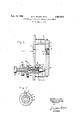
- FIGURE 1 is a view, partially in cross section, of the variable adjustment device according to this invention.
- FIGURE 2 is cross sectional view as viewed along line 22 of FIGURE 1.
- FIGURE 1 there is shown an apparatus constructed according to this invention.
- a housing or wall is shown at 2 and may, for example, comprise a portion of a laser device.
- An aperture 4 is provided for a differential screw with the passage of light through reflecting mirror 6 of a laser device.
- a support 8 is rigidly or integrally attached to wall 2 and a rounded or pointed portion thereof 10 is provided such that a movable member 12 may pivot thereabout.
- a retainer 14 which is threadably secured in retainer 12. This retainer serves to hold mirror 6 in proper position.
- a spring 16 is provided to force member 12 against support 8. In a similar manner, spring 18 is provided at the other end of member 12.
- T hreadably received within wall or housing 2 is a first longitudinal member 20.
- member 20 may be screwed into or out of housing or wall 2 so as to pivot member 12 through pivot point 24 about pivot 10. This changes the orientation of mirror 6 relative to a laser device not shown and to aperature 4.
- Member 20 has relatively coarse thread such that upon rotation thereof, a fairly rapid advancement or retraction of member 20 within housing 2 is accomplished per revolution of knurled knob 22.
- Threadably received on longitudinal member 20 is a lock or stop nut 26. When this member is advanced so as to be forced against housing or wall 2, rotation of member 20 is prevented.
- Threadably received within longitudinal member 20 is a second longitudinal member 28. Shown on member 28 are threads 30 which are received within complementary threads on the interior of longitudinal member 20. A longitudinal portion of member 28 is shown at 32 which has threads 31 oriented in the same direction as threads 28 but of a different pitch. In practice, the pitch of the threads on portion 32 is smaller than the pitch of threads 30.
- a third longitudinal member 34 has interior threads thereon for reception of threads 31 of member 28.
- member 28 When member 28 is turned by means of knurled knob 36, member 28 will advance through longitudinal member 20 while at the same time member 34 is moved in the opposite direction but a smaller rate, such that the net result of turning knob 36 is to advance member 34.
- Member 34 is prevented from rotating within member 20 by means of a slot or groove 38 within member 34 (see FIG. 2).
- Longitudinal member 20 has a pin 40 which is slidable within groove 38 such that rotation of 34 relative to member 20 is prevented.
- a coarse adjustment of member 12 and hence mirror 6 is made by rotation of knurled knob 22.
- lock nut 26 is then advanced so as to be forced against wall 2, thus preventing rotation of member 20 relative to housing or wall 2.
- a fine adjustment is then accomplished by rotation of knurled knob 36, thus forcing member 28 to the right or to the left as desired.
- the fine adjustment is accomplished by the differential screw mechanism which represents the difference in pitch of threads 30 and threads 31.
- Member 34 when knurled knob 36 advances member 28 to the right as viewed in the drawing, will move to the left but at a slower rate, resulting in a net movement to the right as viewed in the figure.
- the advantage of providing the differential pitch arrangement is that it is extremely difiicult to form the necessary fine pitch for fine adjustment.
- a second variable adjustment screw assembly can be provided so that adjustments in the orthogonal direction can be made.
- a differential screw with variable adjustments which comprises;
- a differential screw according to claim 1 wherein exterior threads thereon, said threads having a pitch 10 said means to prevent rotation of said third member reladilferent from that of the threads on said first portive to said first-r member comprises a pin slidable within tion, a slot.
- a third longitudinal member having interior threads thereon corresponding to the threads on said second portion of said second member and slidable axially 15 within said first member when said second member is rotated relative to said first member, and
Landscapes
- Physics & Mathematics (AREA)
- General Physics & Mathematics (AREA)
- Engineering & Computer Science (AREA)
- Automation & Control Theory (AREA)
- Lasers (AREA)
Description
Sept. 24, 1968 R. H. NEUSEL ET AL 3,402,613
DIFFERENTIAL SCREW WITH VARIABLE ADJUSTMENTS v Filed Aug. 1', 1966 Gordon J. Hunt,
Robert H. Neusel,
INVENTORS.
' BY. h J
ATTORNEY,
United States Patent 3,402,613 DIFFERENTIAL SCREW WITH VARIABLE ADJUSTMENTS Robert H. Neusel, Palos Verdes, and Gordon J. Hunt, Redondo Beach, Calif., assignors to TRW Inc., Redondo Beach, Calif., a corporation of Ohio Filed Aug. 1, 1966, Ser. No. 569,365 3 Claims. (Cl. 74-89.15)
This invention relates to variable adjustments.
More particularly this invention relates to an adjusting mechanism which has both coarse and fine adjustments within the same assembly.
There are many examples in the prior art which have a need for an adjusting mechanism which can either pro-v vide a coarse adjustment or a fine adjustment depending on the situation. One of the prime examples illustrating the need for both coarse and fine adjustment of mirrors provided at both ends of a laser cavity. This is particularly the case with a gas laser system. As is well known, the term laser stands for light amplification by stimulated emission of radiation. In the gas laser, radiation is reflected back and forth between mirrors at each end of a laser cavity. In order that a coherent beam be emitted in the proper manner, it is necessary that the orientation of the normal to the mirrors be as parallel as possible. To obtain this, the mirrors typically are pivoted at one side through a housing and an adjustment provided on the other side as more fully brought out in Electronics Magazine, Oct. 27, 1961, pages 45 and 46. A differential screw mechanism is usually provided which, in essence, is a fine pitch mechanism for tuning the mirror to its proper position. The difficulty with this type of mechanism is that a coarse adjustment is not provided such that many turns of the differential screw must be made in order to bring the mirror into proper position for fine adjustment. A similar mechanism, although having a different application, is disclosed in American Machinist Magazine, dated May 19, 1958, page 139. This mechanism likewise lacks a coarse adjustment.
This invention obviates many of the problems of the prior art examples in that both a fine and coarse adjustment is provided in a compact assembly. A particular application of this invention is in the adjustment of laser mirrors.
Briefly, the invention comprises a longitudinal memher having exterior threads thereon which is adapted to be threadably mounted in a housing member for movement therein. Mounted on the longitudinal member or screw is a lock member, whereby the member can be secured against rotation. Within the longitudinal member or screw is a second screw member which is threaded within the first screw and which further has a longitudinal member which is slidable within the first longitudinal member. Upon rotation of the first member, the coarse adjustment can be made. The first member can then be locked against rotation and the interior member screwed within the first member such that a fine adjustment can be made.
The objects and advantages of this invention will become apparent as this description proceeds taken in conjunction with the drawing in which:
FIGURE 1 is a view, partially in cross section, of the variable adjustment device according to this invention, and
FIGURE 2 is cross sectional view as viewed along line 22 of FIGURE 1.
Referring now to FIGURE 1, there is shown an apparatus constructed according to this invention. A housing or wall is shown at 2 and may, for example, comprise a portion of a laser device. An aperture 4 is provided for a differential screw with the passage of light through reflecting mirror 6 of a laser device. A support 8 is rigidly or integrally attached to wall 2 and a rounded or pointed portion thereof 10 is provided such that a movable member 12 may pivot thereabout. Mounted within member 12 is a retainer 14 which is threadably secured in retainer 12. This retainer serves to hold mirror 6 in proper position. A spring 16 is provided to force member 12 against support 8. In a similar manner, spring 18 is provided at the other end of member 12.
T hreadably received within wall or housing 2 is a first longitudinal member 20. Upon rotation of knurled knob 22 which is formed integrally with longitudinal member 20, member 20 may be screwed into or out of housing or wall 2 so as to pivot member 12 through pivot point 24 about pivot 10. This changes the orientation of mirror 6 relative to a laser device not shown and to aperature 4. Member 20 has relatively coarse thread such that upon rotation thereof, a fairly rapid advancement or retraction of member 20 within housing 2 is accomplished per revolution of knurled knob 22. Threadably received on longitudinal member 20 is a lock or stop nut 26. When this member is advanced so as to be forced against housing or wall 2, rotation of member 20 is prevented.
Threadably received within longitudinal member 20 is a second longitudinal member 28. Shown on member 28 are threads 30 which are received within complementary threads on the interior of longitudinal member 20. A longitudinal portion of member 28 is shown at 32 which has threads 31 oriented in the same direction as threads 28 but of a different pitch. In practice, the pitch of the threads on portion 32 is smaller than the pitch of threads 30.
A third longitudinal member 34 has interior threads thereon for reception of threads 31 of member 28. When member 28 is turned by means of knurled knob 36, member 28 will advance through longitudinal member 20 while at the same time member 34 is moved in the opposite direction but a smaller rate, such that the net result of turning knob 36 is to advance member 34. Member 34 is prevented from rotating within member 20 by means of a slot or groove 38 within member 34 (see FIG. 2). Longitudinal member 20 has a pin 40 which is slidable within groove 38 such that rotation of 34 relative to member 20 is prevented.
In operation, a coarse adjustment of member 12 and hence mirror 6 is made by rotation of knurled knob 22. When a position close to that desired is obtained, lock nut 26 is then advanced so as to be forced against wall 2, thus preventing rotation of member 20 relative to housing or wall 2. A fine adjustment is then accomplished by rotation of knurled knob 36, thus forcing member 28 to the right or to the left as desired. The fine adjustment is accomplished by the differential screw mechanism which represents the difference in pitch of threads 30 and threads 31. Member 34, when knurled knob 36 advances member 28 to the right as viewed in the drawing, will move to the left but at a slower rate, resulting in a net movement to the right as viewed in the figure. The advantage of providing the differential pitch arrangement is that it is extremely difiicult to form the necessary fine pitch for fine adjustment.
Although not shown, a second variable adjustment screw assembly can be provided so that adjustments in the orthogonal direction can be made.
Having described this invention, it is to be understood that it is to be limited only by the scope of the claims appended hereto.
What is claimed is:
1. A differential screw with variable adjustments which comprises;
on the exterior thereof and a longitudinal bore therethrough, said bore being threaded on a portion thereof whereby to receive an exteriorly threaded member,
determined axial distance for each revolution of said first member and rotationof said second'member relative to said first member will move said third member a second predetermined distance for each revolution of said secondmember.
second longitudinal member, said second member having a first portion with exterior threads thereon received by the threaded bore of said first member, said second member having a second portion with 2. A difierential screw'according to claim 1 wherein locking means are provided on said first member adapted to prevent rotation of said first member.
3. A differential screw according to claim 1 wherein exterior threads thereon, said threads having a pitch 10 said means to prevent rotation of said third member reladilferent from that of the threads on said first portive to said first-r member comprises a pin slidable within tion, a slot.
a third longitudinal member having interior threads thereon corresponding to the threads on said second portion of said second member and slidable axially 15 within said first member when said second member is rotated relative to said first member, and
means to prevent rotation of said third member relative to said first member,
whereby rotation of said first member within a cor- 20 FRED TTERN,JR.,Przmary Exammer.
respondingly threaded structure will move said first F, D SHOEMAKER Assistant Examiner, member, second member and third member a pre References Cited UNITED STATES PATENTS 3,204,471 9/1965 Remdel 7489.15 3,281,944 11/1966 Youngblood 33163
Claims (1)
1. A DIFFERENTIAL SCREW WITH VARIABLE ADJSUTMENTS WHICH COMPRISES; A FIRST LONGITUDINAL MEMBER, SAID MEMBER HAVING THREADS ON THE EXTERIOR THEREOF AND A LONGITUDINAL BORE THERETHROUGH, SAID BORE BEING THREADED ON A PORTION THEREOF WHEREBY TO RECEIVE AN EXTERIORLY THREADED MEMBER, A SECOND LONGITUDINAL MEMBER, SAID SECOND MEMBER HAVING A FIRST PORTION WITH EXTERIOR THREADS THEREON RECEIVED BY THE THREADED BORE OF SAID FIRST MEMBER, SAID SECOND MEMBER HAVING A SECOND PORTION WITH EXTERIOR THREADS THEREON, SAID THREADS HAVING A PITCH DIFFERENT FROM THAT OF THE THREADS ON SAID FIRST PORTION, A THIRD LONGITUDINAL MEMBER HAVING INTERIOR THREADS THEREON CORRESPONDING TO THE THREADS ON SAID SECOND PORTION OF SAID SECOND MEMBER AND SLIDABLE AXIALLY WITHIN SAID FIRST MEMBER WHEN SAID SECOND MEMBER IS ROTATED RELATIVE TO SAID FIRST MEMBER, AND MEANS TO PREVENT ROTATION OF SAID THIRD MEMBER RELATIVE TO SAID FIRST MEMBER,
Priority Applications (1)
| Application Number | Priority Date | Filing Date | Title |
|---|---|---|---|
| US569365A US3402613A (en) | 1966-08-01 | 1966-08-01 | Differential screw with variable adjustments |
Applications Claiming Priority (1)
| Application Number | Priority Date | Filing Date | Title |
|---|---|---|---|
| US569365A US3402613A (en) | 1966-08-01 | 1966-08-01 | Differential screw with variable adjustments |
Publications (1)
| Publication Number | Publication Date |
|---|---|
| US3402613A true US3402613A (en) | 1968-09-24 |
Family
ID=24275150
Family Applications (1)
| Application Number | Title | Priority Date | Filing Date |
|---|---|---|---|
| US569365A Expired - Lifetime US3402613A (en) | 1966-08-01 | 1966-08-01 | Differential screw with variable adjustments |
Country Status (1)
| Country | Link |
|---|---|
| US (1) | US3402613A (en) |
Cited By (42)
| Publication number | Priority date | Publication date | Assignee | Title |
|---|---|---|---|---|
| US3507100A (en) * | 1967-09-02 | 1970-04-21 | Delbag Luftfilter Gmbh | Thrust generating means for pressing filter packs or filter cells |
| US3520203A (en) * | 1968-11-15 | 1970-07-14 | Eg & G Inc | Positioning device |
| US3541870A (en) * | 1969-03-27 | 1970-11-24 | Monsanto Co | Coarse and vernier adjustable mechanism |
| US3628386A (en) * | 1970-03-05 | 1971-12-21 | Sorvall Inc Ivan | Micrometer stage advance device for scientific instruments or the like |
| US3662661A (en) * | 1970-08-17 | 1972-05-16 | Nasa | Scientific experiment flexible mount |
| US3686964A (en) * | 1969-04-21 | 1972-08-29 | Renault | Tool holders with controlled tool movement |
| US3879112A (en) * | 1973-05-29 | 1975-04-22 | Singer Co | Adjustable mirror mount |
| US3895543A (en) * | 1974-01-11 | 1975-07-22 | Sybron Corp | Adjustment mechanism |
| US4064981A (en) * | 1975-02-24 | 1977-12-27 | The Garrett Corporation | Limit stop |
| US4302982A (en) * | 1980-05-08 | 1981-12-01 | Bell Telephone Laboratories, Incorporated | Key and keyway arrangement |
| US4335523A (en) * | 1981-01-23 | 1982-06-22 | Bryant Gladys M | Tool for adjustably aligning pipe flanges and structural members |
| US4584896A (en) * | 1983-10-25 | 1986-04-29 | Howard Letovsky | Pivot and translation motion control apparatus |
| US4621899A (en) * | 1984-04-09 | 1986-11-11 | The Perkin-Elmer Corporation | Assembly for positioning an optical element |
| US4672776A (en) * | 1983-10-11 | 1987-06-16 | Mccullough Timothy J | Circular blade sharpening device |
| US4732060A (en) * | 1986-02-03 | 1988-03-22 | Stein James A | Clamp for bicycle crank bearing wrench |
| US4745815A (en) * | 1986-12-08 | 1988-05-24 | Sundstrand Corporation | Non-jamming screw actuator system |
| US4750486A (en) * | 1985-08-14 | 1988-06-14 | Butler Philip H | Apparatus for moving a mirror |
| US5204751A (en) * | 1990-08-17 | 1993-04-20 | Hughes Display Products | Target support for projection cathode ray tube |
| US5288292A (en) * | 1992-12-04 | 1994-02-22 | Micro Precision Instrument Company | Keratome with miniature differential micrometer |
| US5299375A (en) * | 1991-01-24 | 1994-04-05 | Laser Devices, Inc. | Laser diode alignment mechanism |
| US5400674A (en) * | 1992-05-08 | 1995-03-28 | New Focus, Inc. | Precision component positioner |
| US5581898A (en) * | 1993-07-30 | 1996-12-10 | Laser Devices, Inc. | Modular sighting laser for a firearm |
| US5596404A (en) * | 1994-12-30 | 1997-01-21 | Albion Instruments, Inc. | Raman gas analysis system with flexible web and differential thread for precision optical alignment |
| US5703683A (en) * | 1996-05-28 | 1997-12-30 | Ohmeda Inc. | Extruded wobble plate optical alignment device |
| US5860548A (en) * | 1993-12-16 | 1999-01-19 | Kerr, Jr.; Jack R. | Junction box for ceiling fan support |
| US5966987A (en) * | 1997-05-28 | 1999-10-19 | Samsung Electronics Co., Ltd. | Controlling device of tunable filter |
| US6450475B1 (en) * | 2000-12-29 | 2002-09-17 | Mustek Systems Inc. | Platform adjustment device for scanner |
| US20070053763A1 (en) * | 2005-09-02 | 2007-03-08 | Jan Allaart | Fastening element for hard constructional components |
| US20080124920A1 (en) * | 2006-11-15 | 2008-05-29 | Clemens Fitz | Fabrication method for an integrated circuit structure |
| US20090220317A1 (en) * | 2008-02-29 | 2009-09-03 | Matthew Travers | Threaded fastener |
| US7819613B2 (en) | 2007-10-31 | 2010-10-26 | Carl Strom | Self-tapping insert and method of utilizing the same to replace damaged bores and threads |
| US20100329816A1 (en) * | 2007-10-31 | 2010-12-30 | Carl Strom | Self-Tapping Insert and Method of Utilizing the Same to Replace Damaged Threads for Hydraulic and Pneumatic Applications |
| US20100329814A1 (en) * | 2007-10-31 | 2010-12-30 | Carl Strom | Self-Tapping Insert and Method of Utilizing the Same to Replace Damaged Bores and Threads |
| US20100329813A1 (en) * | 2007-10-31 | 2010-12-30 | Carl Strom | Self-Tapping and Self-Aligning Insert to Replace Damaged Threads |
| US20100329803A1 (en) * | 2007-10-31 | 2010-12-30 | Carl Strom | Self-aligning thread tap and method of utilizing the same to tap existing bore holes |
| US20120145872A1 (en) * | 2009-06-15 | 2012-06-14 | Toptica Photonics Ag | Kinematic mount |
| US20120237196A1 (en) * | 2011-03-14 | 2012-09-20 | Zhongshan Sirui Photographic Equipment Industry Co., Ltd. | Camera platform locking device |
| US20130037679A1 (en) * | 2011-08-12 | 2013-02-14 | Wesley J. Buth | Kinematic fixture for transparent part metrology |
| US20140175248A1 (en) * | 2012-12-26 | 2014-06-26 | Hon Hai Precision Industry Co., Ltd. | Adjustable support device |
| WO2015054250A3 (en) * | 2013-10-07 | 2015-10-29 | Mts Systems Corporation | Precision force applicator for force transducer calibration |
| US10357855B2 (en) * | 2017-03-28 | 2019-07-23 | Mikhail Borisovich MELNIKOV | Method for tightening a thread joint |
| US20210164512A1 (en) * | 2018-11-21 | 2021-06-03 | Richard C. Sicard | Anti-vibration fastener |
Citations (2)
| Publication number | Priority date | Publication date | Assignee | Title |
|---|---|---|---|---|
| US3204471A (en) * | 1963-07-24 | 1965-09-07 | Spectra Physics | Angle adjusting mechanism for optical elements |
| US3281944A (en) * | 1964-08-28 | 1966-11-01 | Micromatic Hone Corp | Vernier adjustment |
-
1966
- 1966-08-01 US US569365A patent/US3402613A/en not_active Expired - Lifetime
Patent Citations (2)
| Publication number | Priority date | Publication date | Assignee | Title |
|---|---|---|---|---|
| US3204471A (en) * | 1963-07-24 | 1965-09-07 | Spectra Physics | Angle adjusting mechanism for optical elements |
| US3281944A (en) * | 1964-08-28 | 1966-11-01 | Micromatic Hone Corp | Vernier adjustment |
Cited By (55)
| Publication number | Priority date | Publication date | Assignee | Title |
|---|---|---|---|---|
| US3507100A (en) * | 1967-09-02 | 1970-04-21 | Delbag Luftfilter Gmbh | Thrust generating means for pressing filter packs or filter cells |
| US3520203A (en) * | 1968-11-15 | 1970-07-14 | Eg & G Inc | Positioning device |
| US3541870A (en) * | 1969-03-27 | 1970-11-24 | Monsanto Co | Coarse and vernier adjustable mechanism |
| US3686964A (en) * | 1969-04-21 | 1972-08-29 | Renault | Tool holders with controlled tool movement |
| US3628386A (en) * | 1970-03-05 | 1971-12-21 | Sorvall Inc Ivan | Micrometer stage advance device for scientific instruments or the like |
| US3662661A (en) * | 1970-08-17 | 1972-05-16 | Nasa | Scientific experiment flexible mount |
| US3879112A (en) * | 1973-05-29 | 1975-04-22 | Singer Co | Adjustable mirror mount |
| US3895543A (en) * | 1974-01-11 | 1975-07-22 | Sybron Corp | Adjustment mechanism |
| US4064981A (en) * | 1975-02-24 | 1977-12-27 | The Garrett Corporation | Limit stop |
| US4302982A (en) * | 1980-05-08 | 1981-12-01 | Bell Telephone Laboratories, Incorporated | Key and keyway arrangement |
| US4335523A (en) * | 1981-01-23 | 1982-06-22 | Bryant Gladys M | Tool for adjustably aligning pipe flanges and structural members |
| US4672776A (en) * | 1983-10-11 | 1987-06-16 | Mccullough Timothy J | Circular blade sharpening device |
| US4584896A (en) * | 1983-10-25 | 1986-04-29 | Howard Letovsky | Pivot and translation motion control apparatus |
| US4621899A (en) * | 1984-04-09 | 1986-11-11 | The Perkin-Elmer Corporation | Assembly for positioning an optical element |
| US4750486A (en) * | 1985-08-14 | 1988-06-14 | Butler Philip H | Apparatus for moving a mirror |
| US4732060A (en) * | 1986-02-03 | 1988-03-22 | Stein James A | Clamp for bicycle crank bearing wrench |
| US4745815A (en) * | 1986-12-08 | 1988-05-24 | Sundstrand Corporation | Non-jamming screw actuator system |
| US5204751A (en) * | 1990-08-17 | 1993-04-20 | Hughes Display Products | Target support for projection cathode ray tube |
| US5299375A (en) * | 1991-01-24 | 1994-04-05 | Laser Devices, Inc. | Laser diode alignment mechanism |
| US5400674A (en) * | 1992-05-08 | 1995-03-28 | New Focus, Inc. | Precision component positioner |
| US5288292A (en) * | 1992-12-04 | 1994-02-22 | Micro Precision Instrument Company | Keratome with miniature differential micrometer |
| US5581898A (en) * | 1993-07-30 | 1996-12-10 | Laser Devices, Inc. | Modular sighting laser for a firearm |
| US5860548A (en) * | 1993-12-16 | 1999-01-19 | Kerr, Jr.; Jack R. | Junction box for ceiling fan support |
| US5912734A (en) * | 1994-12-30 | 1999-06-15 | Ohmeda Inc. | Raman gas analysis system with ball and socket assembly for precision optical alignment |
| US5596404A (en) * | 1994-12-30 | 1997-01-21 | Albion Instruments, Inc. | Raman gas analysis system with flexible web and differential thread for precision optical alignment |
| US5818579A (en) * | 1994-12-30 | 1998-10-06 | Ohmeda Inc. | Raman gas analysis system with cavity/boss assembly for precision optical alignment |
| US5703683A (en) * | 1996-05-28 | 1997-12-30 | Ohmeda Inc. | Extruded wobble plate optical alignment device |
| US5966987A (en) * | 1997-05-28 | 1999-10-19 | Samsung Electronics Co., Ltd. | Controlling device of tunable filter |
| US6450475B1 (en) * | 2000-12-29 | 2002-09-17 | Mustek Systems Inc. | Platform adjustment device for scanner |
| US8708631B2 (en) * | 2005-09-02 | 2014-04-29 | Hilti Aktiengesellschat | Fastening element for hard constructional components |
| US20070053763A1 (en) * | 2005-09-02 | 2007-03-08 | Jan Allaart | Fastening element for hard constructional components |
| US20080124920A1 (en) * | 2006-11-15 | 2008-05-29 | Clemens Fitz | Fabrication method for an integrated circuit structure |
| US7819613B2 (en) | 2007-10-31 | 2010-10-26 | Carl Strom | Self-tapping insert and method of utilizing the same to replace damaged bores and threads |
| US20100329816A1 (en) * | 2007-10-31 | 2010-12-30 | Carl Strom | Self-Tapping Insert and Method of Utilizing the Same to Replace Damaged Threads for Hydraulic and Pneumatic Applications |
| US20100329814A1 (en) * | 2007-10-31 | 2010-12-30 | Carl Strom | Self-Tapping Insert and Method of Utilizing the Same to Replace Damaged Bores and Threads |
| US20100329813A1 (en) * | 2007-10-31 | 2010-12-30 | Carl Strom | Self-Tapping and Self-Aligning Insert to Replace Damaged Threads |
| US20100329803A1 (en) * | 2007-10-31 | 2010-12-30 | Carl Strom | Self-aligning thread tap and method of utilizing the same to tap existing bore holes |
| US8052360B2 (en) | 2007-10-31 | 2011-11-08 | Carl Strom | Self-aligning thread tap and method of utilizing the same to tap existing bore holes |
| US8439617B2 (en) | 2007-10-31 | 2013-05-14 | Carl Strom | Self-tapping and self-aligning insert to replace damaged threads |
| US8066461B2 (en) * | 2008-02-29 | 2011-11-29 | CBT Technology Inc. | Threaded fastener |
| US20090220317A1 (en) * | 2008-02-29 | 2009-09-03 | Matthew Travers | Threaded fastener |
| US9323025B2 (en) * | 2009-06-15 | 2016-04-26 | Toptica Photonics Ag | Kinematic mount |
| US20120145872A1 (en) * | 2009-06-15 | 2012-06-14 | Toptica Photonics Ag | Kinematic mount |
| US20120237196A1 (en) * | 2011-03-14 | 2012-09-20 | Zhongshan Sirui Photographic Equipment Industry Co., Ltd. | Camera platform locking device |
| US8414202B2 (en) * | 2011-03-14 | 2013-04-09 | Zhongshan Sirui Photographic Equipment Industry Co., Ltd. | Camera platform locking device |
| US9435626B2 (en) * | 2011-08-12 | 2016-09-06 | Corning Incorporated | Kinematic fixture for transparent part metrology |
| US20130037679A1 (en) * | 2011-08-12 | 2013-02-14 | Wesley J. Buth | Kinematic fixture for transparent part metrology |
| US20140175248A1 (en) * | 2012-12-26 | 2014-06-26 | Hon Hai Precision Industry Co., Ltd. | Adjustable support device |
| WO2015054250A3 (en) * | 2013-10-07 | 2015-10-29 | Mts Systems Corporation | Precision force applicator for force transducer calibration |
| CN105593658A (en) * | 2013-10-07 | 2016-05-18 | Mts系统公司 | Precision force applicator for force transducer calibration |
| JP2016532134A (en) * | 2013-10-07 | 2016-10-13 | エムティーエス システムズ コーポレイション | Precision force device for force transducer calibration |
| US9696229B2 (en) | 2013-10-07 | 2017-07-04 | Mts Systems Corporation | Precision force applicator for force transducer calibration |
| CN105593658B (en) * | 2013-10-07 | 2019-08-20 | Mts系统公司 | Accurate force application apparatus for force snesor calibration |
| US10357855B2 (en) * | 2017-03-28 | 2019-07-23 | Mikhail Borisovich MELNIKOV | Method for tightening a thread joint |
| US20210164512A1 (en) * | 2018-11-21 | 2021-06-03 | Richard C. Sicard | Anti-vibration fastener |
Similar Documents
| Publication | Publication Date | Title |
|---|---|---|
| US3402613A (en) | Differential screw with variable adjustments | |
| US3642353A (en) | Adjustable mirror assembly | |
| GB1470755A (en) | Adjustable mirror structure | |
| US384784A (en) | Win dow-reflector | |
| US4037942A (en) | Optical adjustment device | |
| US3476349A (en) | Adjustable support | |
| DE3118822A1 (en) | "MEASURING DEVICE USING A CENTRIFUGAL DEVICE AND METHOD FOR DETERMINING THE NORTHERN DIRECTION IN MEASURING TECHNOLOGY" | |
| US2858732A (en) | Mechanism for eliminating parallax from telescopic sights and the like | |
| US3249008A (en) | Guide means for a barrel carrying an optical element | |
| DE10311247A1 (en) | Portable device for detecting the position and dimensions of an object | |
| US3253509A (en) | Remotely controlled non-glare rear view mirror | |
| US3613464A (en) | Apparatus for orienting beam directing or viewing apparatus | |
| DE2729898C2 (en) | Beam projector | |
| US3727471A (en) | Coarse and fine adjustment and positioning mechanisms | |
| US3226830A (en) | Mechanism for precise angular positioning of optical devices | |
| US4295625A (en) | Precision adjusting device | |
| DE3111104C2 (en) | Binoculars with automatic focusing | |
| US3449970A (en) | Fine and coarse rotation control device | |
| US3262535A (en) | Adjustable screw type limit stop | |
| US3252115A (en) | Tuning arrangement | |
| US3220305A (en) | Multiple projector system | |
| US3754473A (en) | Cam follower assemblies | |
| US3520203A (en) | Positioning device | |
| US4679905A (en) | Linear adjustment apparatus | |
| DE2817237A1 (en) | ROUND VISION PERISCOPE WITH LASER DISTANCE METER |