US3402663A - Continuous noncellular rubber foam stamp - Google Patents
Continuous noncellular rubber foam stamp Download PDFInfo
- Publication number
- US3402663A US3402663A US595376A US59537666A US3402663A US 3402663 A US3402663 A US 3402663A US 595376 A US595376 A US 595376A US 59537666 A US59537666 A US 59537666A US 3402663 A US3402663 A US 3402663A
- Authority
- US
- United States
- Prior art keywords
- stamp
- rubber
- continuous
- ink
- inner frame
- Prior art date
- Legal status (The legal status is an assumption and is not a legal conclusion. Google has not performed a legal analysis and makes no representation as to the accuracy of the status listed.)
- Expired - Lifetime
Links
Images
Classifications
-
- B—PERFORMING OPERATIONS; TRANSPORTING
- B41—PRINTING; LINING MACHINES; TYPEWRITERS; STAMPS
- B41K—STAMPS; STAMPING OR NUMBERING APPARATUS OR DEVICES
- B41K1/00—Portable hand-operated devices without means for supporting or locating the articles to be stamped, i.e. hand stamps; Inking devices or other accessories therefor
- B41K1/36—Details
- B41K1/56—Handles
-
- B—PERFORMING OPERATIONS; TRANSPORTING
- B41—PRINTING; LINING MACHINES; TYPEWRITERS; STAMPS
- B41K—STAMPS; STAMPING OR NUMBERING APPARATUS OR DEVICES
- B41K1/00—Portable hand-operated devices without means for supporting or locating the articles to be stamped, i.e. hand stamps; Inking devices or other accessories therefor
- B41K1/36—Details
- B41K1/38—Inking devices; Stamping surfaces
Definitions
- a stamp pad having an ink pad and stamp plate secured in a lower compartment beneath a transverse wall in an inner frame, an outer frame being telescoped over the inner frame and engaging a spring acting on a sleeve which is interposed between the inner and outer frames Y and which has a lower edge extending below the plate when the spring is relaxed.
- This invention relates to a stamp made of a continuous noncellular rubber foam such as a sponge rubber, and more specifically to a rubber foam stamp of such construction which comprises an inner frame accommodating an ink pad and a continuous noncellular rubber plate and having a bottom provided with ink filling ports, an outer frame having inwardly protruding steps which engage with outer protrusions on the top edges of both left and right side walls of the inner frame, an elastic member or members interposed between the outer and inner frames in such manner as to permit the outer frame to be moved slidingly in the vertical direction lby the application of a pressure on the elastic member, and an inverted L-shaped sleeve, the upper folded edges of which are supported between the lower end of the elastic member and stepped portions of the inner frame, said sleeve being normally kept extended below the sponge rubber plate.
- an ordinary rubber stamp has been made by engraving letters, numerals and other symbols on the surface of a stamp or by applying a rubber plate on the base, such rubber plate being obtained by compressing unvulcanized rubber on the engraved original model and vulcanizing said rubber. Therefore, in order to use such rubber stamp, it is required that ink be applied to surface of the stamp by using a stamp box for each stamping operation.
- the present invention contemplates providing a continuous noncellular rubber foam stamp made of a material adaptable for retaining ink at all times such as a sponge rubber.
- Another object of the invention is to provide a continuous noncellular rubber foam stamp which is equipped with a sleeve around the periphery of the plate surface in order to protect the surface against staining in the course of the return to its normal position after each impression.
- Another object of the invention is to provide a continuous noncellular rubber foam stamp which is always ready for effective use as it can be replenished with stamping ink in the pad simply by opening the top cover and supplying the ink to the pad.
- Another object of the invention is to provide a continuous potrous noncellular rubber foam stamp in which the protrusions of the inner frame which support the ink pad and rubber plate surface therein are freely engageable with the inwardly protruding steps of the outer frame which fit with the cover so that the inner and outer frames can be engaged with each other with simplicity and surety.
- Still another object of the invention is to provide a continuous noncellular rubber foam stamp which is equipped with elastic members of a tough synthetic resin material having excellent solvent resistance, shock resistance, elasticity and fatigue limit, disposed along the outer front side and back side of the inner frame and also inside of the outer frame, whereby the elastic function of the stamp can be maintained with negligible loss after repeated stamping operations.
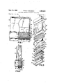
- FIGURE 1 is a front elevational view, partly broken away, of a stamp according to the present invention.
- FIGURE 2 is a side elevational view, partly broken away, of the stamp shown in FIGURE l;
- FIGURE 3 is an exploded view of a stamp shown in FIGURES 1 and 2 in accordance with the present invention.
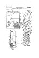
- FIGURE 4 is a front elevational view, partly broken away, of another form of stamp according to the invention.
- FIGURE 5 is a side elevational view, partly broken away, of the stamp shown in FIGURE 3;
- FIGURE 6 is an exploded view of a stamp shown in FIGURES 4 and 5 in accordance with another form of the present invention.
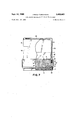
- FIGURE 7 is a view showing the relative position of the elements when the stamp is in its printing position.
- numeral 1 indicates an ink filling port or aperture in a transverse wall 2 of an inner frame 3 constructed in the shape of a hollow box-like member.
- the wall 2 divides the frame 3 into upper and lower chambers or compartments and there is secured in the compartment below wall 2, an ink pad 4 of felt or like material and a rubber plate 5 having a great number of continuous noncellular rubber foams, combined in the order mentioned.
- the left and right side walls of the inner frame 3 are provided on the top edges with outward protrusions 11, which freely engage with the heads of inwardly protruding steps 12 on the left and right side walls of an outer frame 10, also of hollow box-like construction.
- a coil spring 8 In the space between shoulders or stepped portions 6 of inner frame 3 and a shoulder or step 19 formed by extensions 10' of outer frame 10, is interposed a coil spring 8. Furthermore, there is secured between the bottom end of the spring 8 and the stepped portions 6, folded top edges 7 of a sleeve 7 which is of inverted L-shape in cross section. The lower portion of the sleeve 7 for covering the rubber plate 5 normally protrudes below the rubber plate 5. The periphery of the rubber plate 5 is secured to the lower periphery of the inner frame 3 by an annular retainer 13.
- 'by numeral 9 is a cover which fits on the upper portion of the upper frame lll and which is provided with a recess 15 on the top for indicating the letters, numerals or other symbols to be stamped.
- a seating plate 14 of porous rigid synthetic resin or the like is interposed between the ink pad 4 and the rulbber plate 5 according to necessity.
- the stamp is used by gripping it by the cover 9 and applying a stamping pressure. lUnder the pressure, the spring 8 borne by the stepped portions 6 of inner frame 3 through the folded top edges 7 of sleeve 7 is compressed, and at the time of each impression the sleeve 7 which normally covers the rubber plate exposes the rubber plate 5 below the lower opening. Therefore the ink contained beforehand in the ink pad 4 which is accommodated in the compartment beneath the wall 2 permeates constantly through the numerous continuous pores of the rubber plate 5 down to the under face. Hence, there is no need of inking the plate surface before each impression and clear stamping of letters and other symbols is always ensured.
- the sleeve 7 After each stamping operation, the sleeve 7 is brought back by the recovery force of spring 8 to the original state in which the sleeve 7 covers the rubber plate 5 in such manner that it can positively protect the latter against dirt and contact with other materials.
- the ink pad 4 For replenishment of the ink pad 4 with ink, it is merely necessary to remove the cover 9 from the top opening of the outer frame 10 and pour in stamping ink.
- the pad ⁇ 4 is easily impregnated with ink which is led through the tiling ports 1 in the wall 2 of the inner frame 3.
- FIGURES 3 and 4 there is shown another form of rubber stamp according to the present invention, wherein like parts are designated as in FIGURES 1 and 2 except for the following.
- the coil spring used in the rst embodiment as interposed between the outside of inner frame 3 and outer frame 10 is replaced by substantially X shaped elastic members 16 of a tough synthetic resin material, eg., polyacetal resin, having forked 'hanches 17, 17 and legs 18, 18 on the left and right as viewed in FIGURE 6 and which are disposed on the front and back sides of inner frame 3.
- a tough synthetic resin material eg., polyacetal resin
- FIGURES 3 and 4 Since the embodiment of the invention illustrated in FIGURES 3 and 4 is constructed as above described, it functions in the following fway.
- the stamp When the stamp is gripped on the cover 9 and is pressed against paper or other material to be stamped, the elastic ⁇ members 16 are uniformly compressed between the supporting steps 19 and the folded top edges 7'.
- the inner frame 3 descends together with the outer frame 10 until the rubber plate 5 at the lower end of inner frame 3 is somewhat exposed at a distance Ifrom the lower extensions 10' of outer frame 10 and is pressed against the paper surface.
- the ink which is contained beforehand in the ink pad of felt or like material accommodated in the compartment beneath the wall 2 permeates constantly through the numerous continuous pores of rubber plate S down to the under face thereof and permits letters, numerals and other symbols on the rubber plate to be distinctly reproduced on the paper surface.
- the stamp is freed from the stamping pressure and is held upwardly from the paper surface after impression, the compressed branches 17, 17' and legs 18, 18' of elastic members 16 are relaxed and assume the original open state, whereby the sleeve 7 returns to A the position where it covers the rubber' plate 5 which is thus positively kept from being stained through contact with any other material.
- the ink pad 4 may be replenished with ink by the same procedure as in the ernbodiment shown in FIGURES l and 2.
- a stamp comprising an inner frame constituted Vas a hollow box-like member with opposite open ends, said frame including an intermediate transverse wall dividing the frame into upper and lower chambers, said wall having apertures therein, yan ink pad and a rubber stamp plate secured in the lower chamber of said frame in the above order from the transverse wall, an outer frame also constituted as a hollow box-like member surrounding the inner frame, means detachably connecting the frames t0- gethcr in telescoped relation, said frame having shoulders facing one another, a hollow sleeve interposed between the inner and outer frames and including an upper folded edge between the shoulders of the frames, and elastic means between the folded edge of the sleeve and the shoulders of the outer frame to permit the outer frame to be slidably moved relative to thc sleeve, the sleeve hav ing a lower edge extending below the level of the rubber plate with the elastic means relaxed.
- a stamp according to claim 1 wherein said means which detachably connects the frames comprises inwardly protruding steps on the outer frame and outer protrusions on the inner frame engaging said steps.
- a stamp according to claim 1 comprising an annular retainer securing the rubber stamp plate to the inner frame in said lower chamber.
- a stamp according to claim 1 comprising a Iremovable cover mounted atop the outer frame, said cover being provided with a recess for indicating the letters, numerals and other symbols which form the rubber plate surface for stamping.
- a stamp according to claim 1 wherein the rubber stamp plate is constituted of sponge rubber.
- a stamp according to clairn 1 wherein said elastic means comprises a pair of X-shaped members between the inner and outer frames.
- a stamp according to claim 7 wherein the X-shaped members are constituted of a synthetic resin material Selected from the group consisting of polyacetal resin or polyamide resin.
Description
SePt- 24, 1968 TAKAJI FuNAHAsl-u 3,402,663
CONTINUOUS NONCELLULAR RUBBER FOAM STAMP Filed NOV. 18, 1966 3 Sheets-Sheet l Sept. 24, 1968 TAKAJl FUNAHASHI 3,402,663
CONTINUOUS NONCELLULAR RUBBER FOAM-STAMP Filed Nov. 18, 196e 3 Sheets-Sheet 2 FIGA 5 "3A SePtf 24, 1968 TAKAJI FUNAHASHI 3,402,663
CONTINUOUS NONCELLULAR RUBBER FOAM STAMP United States Patent O ABSTRACT OF THE DISCLOSURE A stamp pad having an ink pad and stamp plate secured in a lower compartment beneath a transverse wall in an inner frame, an outer frame being telescoped over the inner frame and engaging a spring acting on a sleeve which is interposed between the inner and outer frames Y and which has a lower edge extending below the plate when the spring is relaxed.
This invention relates to a stamp made of a continuous noncellular rubber foam such as a sponge rubber, and more specifically to a rubber foam stamp of such construction which comprises an inner frame accommodating an ink pad and a continuous noncellular rubber plate and having a bottom provided with ink filling ports, an outer frame having inwardly protruding steps which engage with outer protrusions on the top edges of both left and right side walls of the inner frame, an elastic member or members interposed between the outer and inner frames in such manner as to permit the outer frame to be moved slidingly in the vertical direction lby the application of a pressure on the elastic member, and an inverted L-shaped sleeve, the upper folded edges of which are supported between the lower end of the elastic member and stepped portions of the inner frame, said sleeve being normally kept extended below the sponge rubber plate.
In the prior art, an ordinary rubber stamp has been made by engraving letters, numerals and other symbols on the surface of a stamp or by applying a rubber plate on the base, such rubber plate being obtained by compressing unvulcanized rubber on the engraved original model and vulcanizing said rubber. Therefore, in order to use such rubber stamp, it is required that ink be applied to surface of the stamp by using a stamp box for each stamping operation. The present invention contemplates providing a continuous noncellular rubber foam stamp made of a material adaptable for retaining ink at all times such as a sponge rubber.
It is an object of the present invention to provide a continuous noncellular rubber foam stamp which permits stamping of letters, numerals and other symbols on paper and other surfaces, simply and surely by self inking of the stamp face or rubber plate surface without any trouble of inking on the stamp face or rubber plate surface before each stamping operation.
Another object of the invention is to provide a continuous noncellular rubber foam stamp which is equipped with a sleeve around the periphery of the plate surface in order to protect the surface against staining in the course of the return to its normal position after each impression.
Another object of the invention is to provide a continuous noncellular rubber foam stamp which is always ready for effective use as it can be replenished with stamping ink in the pad simply by opening the top cover and supplying the ink to the pad.
Another object of the invention is to provide a continuous potrous noncellular rubber foam stamp in which the protrusions of the inner frame which support the ink pad and rubber plate surface therein are freely engageable with the inwardly protruding steps of the outer frame which fit with the cover so that the inner and outer frames can be engaged with each other with simplicity and surety.
Still another object of the invention is to provide a continuous noncellular rubber foam stamp which is equipped with elastic members of a tough synthetic resin material having excellent solvent resistance, shock resistance, elasticity and fatigue limit, disposed along the outer front side and back side of the inner frame and also inside of the outer frame, whereby the elastic function of the stamp can be maintained with negligible loss after repeated stamping operations.
The advantageous features and objects of the present invention will be more fully understood from the following detailed description taken in connection with the accompanying drawings, in which:
FIGURE 1 is a front elevational view, partly broken away, of a stamp according to the present invention;
FIGURE 2 is a side elevational view, partly broken away, of the stamp shown in FIGURE l;
FIGURE 3 is an exploded view of a stamp shown in FIGURES 1 and 2 in accordance with the present invention;
FIGURE 4 is a front elevational view, partly broken away, of another form of stamp according to the invention;
FIGURE 5 is a side elevational view, partly broken away, of the stamp shown in FIGURE 3;
FIGURE 6 is an exploded view of a stamp shown in FIGURES 4 and 5 in accordance with another form of the present invention; and
FIGURE 7 is a view showing the relative position of the elements when the stamp is in its printing position.
In the drawings, numeral 1 indicates an ink filling port or aperture in a transverse wall 2 of an inner frame 3 constructed in the shape of a hollow box-like member. The wall 2 divides the frame 3 into upper and lower chambers or compartments and there is secured in the compartment below wall 2, an ink pad 4 of felt or like material and a rubber plate 5 having a great number of continuous noncellular rubber foams, combined in the order mentioned. The left and right side walls of the inner frame 3 are provided on the top edges with outward protrusions 11, which freely engage with the heads of inwardly protruding steps 12 on the left and right side walls of an outer frame 10, also of hollow box-like construction. In the space between shoulders or stepped portions 6 of inner frame 3 and a shoulder or step 19 formed by extensions 10' of outer frame 10, is interposed a coil spring 8. Furthermore, there is secured between the bottom end of the spring 8 and the stepped portions 6, folded top edges 7 of a sleeve 7 which is of inverted L-shape in cross section. The lower portion of the sleeve 7 for covering the rubber plate 5 normally protrudes below the rubber plate 5. The periphery of the rubber plate 5 is secured to the lower periphery of the inner frame 3 by an annular retainer 13.
Generally designated 'by numeral 9 is a cover which fits on the upper portion of the upper frame lll and which is provided with a recess 15 on the top for indicating the letters, numerals or other symbols to be stamped. A seating plate 14 of porous rigid synthetic resin or the like is interposed between the ink pad 4 and the rulbber plate 5 according to necessity.
With the construction as described hereinabove, the stamp is used by gripping it by the cover 9 and applying a stamping pressure. lUnder the pressure, the spring 8 borne by the stepped portions 6 of inner frame 3 through the folded top edges 7 of sleeve 7 is compressed, and at the time of each impression the sleeve 7 which normally covers the rubber plate exposes the rubber plate 5 below the lower opening. Therefore the ink contained beforehand in the ink pad 4 which is accommodated in the compartment beneath the wall 2 permeates constantly through the numerous continuous pores of the rubber plate 5 down to the under face. Hence, there is no need of inking the plate surface before each impression and clear stamping of letters and other symbols is always ensured. After each stamping operation, the sleeve 7 is brought back by the recovery force of spring 8 to the original state in which the sleeve 7 covers the rubber plate 5 in such manner that it can positively protect the latter against dirt and contact with other materials. For replenishment of the ink pad 4 with ink, it is merely necessary to remove the cover 9 from the top opening of the outer frame 10 and pour in stamping ink. The pad `4 is easily impregnated with ink which is led through the tiling ports 1 in the wall 2 of the inner frame 3. There is no possibility of the inner frame 3 being disconnected from the outer frame 10 because the outwardly protruding edges 11 on the top edges of left and right side walls of inner frame 3 are engaged with protruding steps 12 inwardly formed of the left and right side walls of outer frame 10.
=In FIGURES 3 and 4 there is shown another form of rubber stamp according to the present invention, wherein like parts are designated as in FIGURES 1 and 2 except for the following. In the embodiment illustrated in FIGURES 3 and 4, the coil spring used in the rst embodiment as interposed between the outside of inner frame 3 and outer frame 10 is replaced by substantially X shaped elastic members 16 of a tough synthetic resin material, eg., polyacetal resin, having forked ' hanches 17, 17 and legs 18, 18 on the left and right as viewed in FIGURE 6 and which are disposed on the front and back sides of inner frame 3. These elastic members 16, are fitted in position by placing the branches 17, 17' of the elastic members 16 against lugs 19 formed by extensions 10 of outer frame 10 while permitting the legs 18, 18' of the elastic members 16 to be supported by the folded top edges 7 of sleeve 7 above the steps 6 of inner fframe 3. Numerals 20` and 21 indicate an auxiliary ink pad of felt or like material and an ink adjusting plate of porous rigid synthetic resin or the like, respectively, which are interposed if necessary between the ink pad 4 and the rubber plate 5.
Since the embodiment of the invention illustrated in FIGURES 3 and 4 is constructed as above described, it functions in the following fway. When the stamp is gripped on the cover 9 and is pressed against paper or other material to be stamped, the elastic `members 16 are uniformly compressed between the supporting steps 19 and the folded top edges 7'. Thus, while the lower portion of sleeve 7 which normally covers the rubber plate 5 is in contact with paper surface, the inner frame 3 descends together with the outer frame 10 until the rubber plate 5 at the lower end of inner frame 3 is somewhat exposed at a distance Ifrom the lower extensions 10' of outer frame 10 and is pressed against the paper surface. Accordingly, the ink which is contained beforehand in the ink pad of felt or like material accommodated in the compartment beneath the wall 2 permeates constantly through the numerous continuous pores of rubber plate S down to the under face thereof and permits letters, numerals and other symbols on the rubber plate to be distinctly reproduced on the paper surface. When the stamp is freed from the stamping pressure and is held upwardly from the paper surface after impression, the compressed branches 17, 17' and legs 18, 18' of elastic members 16 are relaxed and assume the original open state, whereby the sleeve 7 returns to A the position where it covers the rubber' plate 5 which is thus positively kept from being stained through contact with any other material. The ink pad 4 may be replenished with ink by the same procedure as in the ernbodiment shown in FIGURES l and 2.
Various modifications of the present invention are possible without being restricted to the embodiments disclosed herein and without departing from the scope and spirit of the invention as delined in the appended claims.
I claim:
1. A stamp comprising an inner frame constituted Vas a hollow box-like member with opposite open ends, said frame including an intermediate transverse wall dividing the frame into upper and lower chambers, said wall having apertures therein, yan ink pad and a rubber stamp plate secured in the lower chamber of said frame in the above order from the transverse wall, an outer frame also constituted as a hollow box-like member surrounding the inner frame, means detachably connecting the frames t0- gethcr in telescoped relation, said frame having shoulders facing one another, a hollow sleeve interposed between the inner and outer frames and including an upper folded edge between the shoulders of the frames, and elastic means between the folded edge of the sleeve and the shoulders of the outer frame to permit the outer frame to be slidably moved relative to thc sleeve, the sleeve hav ing a lower edge extending below the level of the rubber plate with the elastic means relaxed.
2. A stamp according to claim 1 wherein said means which detachably connects the frames comprises inwardly protruding steps on the outer frame and outer protrusions on the inner frame engaging said steps.
3. A stamp according to claim 1 wherein said elastic means is a coil spring.
4. A stamp according to claim 1 comprising an annular retainer securing the rubber stamp plate to the inner frame in said lower chamber.
5. A stamp according to claim 1 comprising a Iremovable cover mounted atop the outer frame, said cover being provided with a recess for indicating the letters, numerals and other symbols which form the rubber plate surface for stamping.
6. A stamp according to claim 1 wherein the rubber stamp plate is constituted of sponge rubber.
7. A stamp according to clairn 1 wherein said elastic means comprises a pair of X-shaped members between the inner and outer frames.
8. A stamp according to claim 7 wherein the X-shaped members are constituted of a synthetic resin material Selected from the group consisting of polyacetal resin or polyamide resin.
References Cited UNITED STATES PATENTS 593,482 1l/l897 Mandt 267--7 593,946 11/1897 Mandt 267-7 1,887,310 11/1932 King et al 267-1 2,318,465 5/1943 Chollar lOl-125 2,335,992 12/1943 Biskind lOl-125 2,392,521 1/1946 Chollar 101-327 2,819,668 1/1958 McAneny 10i-125 2,900,902 8/1959 Becker lOl-368 2,950,676 8/1960 Weissman et al 101-334 3,023,701 3/1962 Anderson lOl-405 FOREIGN PATENTS 671,807 5/1952 Great Britain.
ROBERT E. PULFREY, Primary Examiner.
H. DINITZ, Assistant Examiner.
Priority Applications (1)
| Application Number | Priority Date | Filing Date | Title |
|---|---|---|---|
| US595376A US3402663A (en) | 1966-11-18 | 1966-11-18 | Continuous noncellular rubber foam stamp |
Applications Claiming Priority (1)
| Application Number | Priority Date | Filing Date | Title |
|---|---|---|---|
| US595376A US3402663A (en) | 1966-11-18 | 1966-11-18 | Continuous noncellular rubber foam stamp |
Publications (1)
| Publication Number | Publication Date |
|---|---|
| US3402663A true US3402663A (en) | 1968-09-24 |
Family
ID=24383005
Family Applications (1)
| Application Number | Title | Priority Date | Filing Date |
|---|---|---|---|
| US595376A Expired - Lifetime US3402663A (en) | 1966-11-18 | 1966-11-18 | Continuous noncellular rubber foam stamp |
Country Status (1)
| Country | Link |
|---|---|
| US (1) | US3402663A (en) |
Cited By (23)
| Publication number | Priority date | Publication date | Assignee | Title |
|---|---|---|---|---|
| US3631799A (en) * | 1968-03-01 | 1972-01-04 | Takaji Funahashi | Rubber stamper with interchangeable printing blocks |
| US3832947A (en) * | 1970-10-21 | 1974-09-03 | Funahashi Takaji | Simplified, self-inking hand stamp |
| US3952653A (en) * | 1975-03-24 | 1976-04-27 | Fairfield Marking Products, Inc. | Stamp device |
| US3955499A (en) * | 1973-05-28 | 1976-05-11 | Takaji Funahashi | Rotary rubber stamp |
| US3964383A (en) * | 1974-09-24 | 1976-06-22 | Patrick Delligatti | Reciprocating self-contained marking device |
| US4029012A (en) * | 1975-12-18 | 1977-06-14 | Identicator Corporation | Two-part inkless applicator for fingerprints |
| US4182261A (en) * | 1975-12-18 | 1980-01-08 | Identicator Corporation | Credit card printer for fingerprints and solutions |
| EP0024374A1 (en) * | 1979-08-14 | 1981-03-04 | Tokyo Electric Co. Ltd. | A product name stamping device for label printers |
| US4289070A (en) * | 1979-06-26 | 1981-09-15 | Cosco Industries, Inc. | Rubber stamp |
| WO1982000426A1 (en) * | 1980-07-30 | 1982-02-18 | H Werwa | Process for fabricating a self-contained ink applicator for continuous imprinting on non-absorbent surfaces |
| US4553476A (en) * | 1974-12-30 | 1985-11-19 | Monarch Marking Systems, Inc. | Ink pad |
| US4649820A (en) * | 1984-01-05 | 1987-03-17 | Vance David E | Hand held impact printer |
| US4676162A (en) * | 1985-06-17 | 1987-06-30 | Porelon, Inc. | Rubber stamp |
| US4852489A (en) * | 1987-11-18 | 1989-08-01 | M&R Marking Systems, Inc. | Self-inking stamping device |
| US5359931A (en) * | 1989-03-10 | 1994-11-01 | Voorhees Scott W | Highlighting for photocopiers and facsimile machines |
| US5417505A (en) * | 1989-03-10 | 1995-05-23 | Voorhees; Scott W. | Tone pattern applying instrument |
| US5483880A (en) * | 1993-11-30 | 1996-01-16 | Brother Kogyo Kabushiki Kaisha | Stamp unit whose print face portion is formed of a heat sensitive stencil paper |
| US5517916A (en) * | 1994-09-14 | 1996-05-21 | M&R Marking Systems, Inc. | Self-inking stamp |
| US5826515A (en) * | 1997-01-29 | 1998-10-27 | Binney & Smith Inc. | Stamping device |
| USD408051S (en) * | 1997-01-17 | 1999-04-13 | Colop Stempelerzeugung Skopek Gmbh & Co. Kg. | Combined stamp and protective cover |
| US20110265809A1 (en) * | 2009-11-26 | 2011-11-03 | Chan-Hwa Jeon | Portable nail art device and nail art method using the same |
| US20140096695A1 (en) * | 2012-10-05 | 2014-04-10 | Craig J. Petersen | Method and system for a self-inking stamp cartridge |
| CN107225872A (en) * | 2016-03-23 | 2017-10-03 | 沙奇哈塔株式会社 | Reversible type seal |
Citations (11)
| Publication number | Priority date | Publication date | Assignee | Title |
|---|---|---|---|---|
| US593482A (en) * | 1897-11-09 | Wagon bolster-spring | ||
| US593946A (en) * | 1897-11-16 | Wagon bolster-spring | ||
| US1887310A (en) * | 1930-08-20 | 1932-11-08 | John H King | Cushion structure |
| US2318465A (en) * | 1940-06-21 | 1943-05-04 | Ncr Co | Printing means |
| US2335992A (en) * | 1941-11-14 | 1943-12-07 | John J Nichols | Hand stamp and stencil therefor |
| US2392521A (en) * | 1942-02-12 | 1946-01-08 | Ncr Co | Porous resilient printing plate |
| GB671807A (en) * | 1949-07-22 | 1952-05-07 | Ncr Co | Hand stamp |
| US2819668A (en) * | 1955-02-23 | 1958-01-14 | Edward G Mcaneny | Hand stamp |
| US2900902A (en) * | 1958-04-14 | 1959-08-25 | Becker Henry | Uniform pressure hand stamp |
| US2950676A (en) * | 1957-05-15 | 1960-08-30 | Bankers & Merchants Inc | Stamp |
| US3023701A (en) * | 1959-08-07 | 1962-03-06 | Stanley E Anderson | Stamp body and handle construction |
-
1966
- 1966-11-18 US US595376A patent/US3402663A/en not_active Expired - Lifetime
Patent Citations (11)
| Publication number | Priority date | Publication date | Assignee | Title |
|---|---|---|---|---|
| US593482A (en) * | 1897-11-09 | Wagon bolster-spring | ||
| US593946A (en) * | 1897-11-16 | Wagon bolster-spring | ||
| US1887310A (en) * | 1930-08-20 | 1932-11-08 | John H King | Cushion structure |
| US2318465A (en) * | 1940-06-21 | 1943-05-04 | Ncr Co | Printing means |
| US2335992A (en) * | 1941-11-14 | 1943-12-07 | John J Nichols | Hand stamp and stencil therefor |
| US2392521A (en) * | 1942-02-12 | 1946-01-08 | Ncr Co | Porous resilient printing plate |
| GB671807A (en) * | 1949-07-22 | 1952-05-07 | Ncr Co | Hand stamp |
| US2819668A (en) * | 1955-02-23 | 1958-01-14 | Edward G Mcaneny | Hand stamp |
| US2950676A (en) * | 1957-05-15 | 1960-08-30 | Bankers & Merchants Inc | Stamp |
| US2900902A (en) * | 1958-04-14 | 1959-08-25 | Becker Henry | Uniform pressure hand stamp |
| US3023701A (en) * | 1959-08-07 | 1962-03-06 | Stanley E Anderson | Stamp body and handle construction |
Cited By (26)
| Publication number | Priority date | Publication date | Assignee | Title |
|---|---|---|---|---|
| US3631799A (en) * | 1968-03-01 | 1972-01-04 | Takaji Funahashi | Rubber stamper with interchangeable printing blocks |
| US3832947A (en) * | 1970-10-21 | 1974-09-03 | Funahashi Takaji | Simplified, self-inking hand stamp |
| US3955499A (en) * | 1973-05-28 | 1976-05-11 | Takaji Funahashi | Rotary rubber stamp |
| US3964383A (en) * | 1974-09-24 | 1976-06-22 | Patrick Delligatti | Reciprocating self-contained marking device |
| US4553476A (en) * | 1974-12-30 | 1985-11-19 | Monarch Marking Systems, Inc. | Ink pad |
| US3952653A (en) * | 1975-03-24 | 1976-04-27 | Fairfield Marking Products, Inc. | Stamp device |
| US4029012A (en) * | 1975-12-18 | 1977-06-14 | Identicator Corporation | Two-part inkless applicator for fingerprints |
| US4182261A (en) * | 1975-12-18 | 1980-01-08 | Identicator Corporation | Credit card printer for fingerprints and solutions |
| US4289070A (en) * | 1979-06-26 | 1981-09-15 | Cosco Industries, Inc. | Rubber stamp |
| EP0024374A1 (en) * | 1979-08-14 | 1981-03-04 | Tokyo Electric Co. Ltd. | A product name stamping device for label printers |
| WO1982000426A1 (en) * | 1980-07-30 | 1982-02-18 | H Werwa | Process for fabricating a self-contained ink applicator for continuous imprinting on non-absorbent surfaces |
| US4325179A (en) * | 1980-07-30 | 1982-04-20 | Harold Werwa | Process for fabricating a self-contained ink applicator for continuous imprinting on non-absorbent surfaces |
| US4649820A (en) * | 1984-01-05 | 1987-03-17 | Vance David E | Hand held impact printer |
| US4676162A (en) * | 1985-06-17 | 1987-06-30 | Porelon, Inc. | Rubber stamp |
| US4852489A (en) * | 1987-11-18 | 1989-08-01 | M&R Marking Systems, Inc. | Self-inking stamping device |
| US5359931A (en) * | 1989-03-10 | 1994-11-01 | Voorhees Scott W | Highlighting for photocopiers and facsimile machines |
| US5417505A (en) * | 1989-03-10 | 1995-05-23 | Voorhees; Scott W. | Tone pattern applying instrument |
| US5483880A (en) * | 1993-11-30 | 1996-01-16 | Brother Kogyo Kabushiki Kaisha | Stamp unit whose print face portion is formed of a heat sensitive stencil paper |
| US5517916A (en) * | 1994-09-14 | 1996-05-21 | M&R Marking Systems, Inc. | Self-inking stamp |
| USD408051S (en) * | 1997-01-17 | 1999-04-13 | Colop Stempelerzeugung Skopek Gmbh & Co. Kg. | Combined stamp and protective cover |
| US5826515A (en) * | 1997-01-29 | 1998-10-27 | Binney & Smith Inc. | Stamping device |
| US20110265809A1 (en) * | 2009-11-26 | 2011-11-03 | Chan-Hwa Jeon | Portable nail art device and nail art method using the same |
| US20140096695A1 (en) * | 2012-10-05 | 2014-04-10 | Craig J. Petersen | Method and system for a self-inking stamp cartridge |
| US9550388B2 (en) * | 2012-10-05 | 2017-01-24 | Trodat Gmbh | Method and system for self-inking stamp cartridge |
| CN107225872A (en) * | 2016-03-23 | 2017-10-03 | 沙奇哈塔株式会社 | Reversible type seal |
| EP3222434A3 (en) * | 2016-03-23 | 2017-12-13 | Shachihata Inc. | Reverse type stamp |
Similar Documents
| Publication | Publication Date | Title |
|---|---|---|
| US3402663A (en) | Continuous noncellular rubber foam stamp | |
| US3855925A (en) | Pocket hand stamp | |
| US4970954A (en) | Self inking hand stamp | |
| US3442209A (en) | Rubber stamp | |
| US3832947A (en) | Simplified, self-inking hand stamp | |
| EP1322477B1 (en) | Hand stamp and method of assembling hand stamp | |
| US6968781B1 (en) | Ink cartridge for hand stamp | |
| US3631799A (en) | Rubber stamper with interchangeable printing blocks | |
| US5586500A (en) | Stencil stamp | |
| US2598806A (en) | Hand stamp | |
| US6892637B2 (en) | Self-inking stamp with ink cartridge barrier | |
| US1796137A (en) | Resilient stamp pad | |
| CA1138712A (en) | Rubber stamp | |
| KR200420183Y1 (en) | Painting with built-in ink supply | |
| JP5006819B2 (en) | Penetration mark | |
| JP5096753B2 (en) | Continuous stamp type stamp | |
| US6189451B1 (en) | Stamp for providing imprint on bulging surface | |
| US1834629A (en) | Self inking stamp holder | |
| US796132A (en) | Hand-stamp. | |
| US1596130A (en) | Inking or stamp pad | |
| CN215360580U (en) | Stamp convenient for adding stamp-pad ink | |
| US3646907A (en) | Inking pad assembly | |
| JP3686000B2 (en) | Combination mark | |
| JP2504315Y2 (en) | Stamp | |
| US777836A (en) | Hand-stamp. |