US3439358A - Activity detectors - Google Patents
Activity detectors Download PDFInfo
- Publication number
- US3439358A US3439358A US510488A US3439358DA US3439358A US 3439358 A US3439358 A US 3439358A US 510488 A US510488 A US 510488A US 3439358D A US3439358D A US 3439358DA US 3439358 A US3439358 A US 3439358A
- Authority
- US
- United States
- Prior art keywords
- animal
- receiving
- signal
- antenna
- signals
- Prior art date
- Legal status (The legal status is an assumption and is not a legal conclusion. Google has not performed a legal analysis and makes no representation as to the accuracy of the status listed.)
- Expired - Lifetime
Links
Images


Classifications
-
- G—PHYSICS
- G08—SIGNALLING
- G08B—SIGNALLING OR CALLING SYSTEMS; ORDER TELEGRAPHS; ALARM SYSTEMS
- G08B21/00—Alarms responsive to a single specified undesired or abnormal condition and not otherwise provided for
- G08B21/02—Alarms for ensuring the safety of persons
- G08B21/04—Alarms for ensuring the safety of persons responsive to non-activity, e.g. of elderly persons
- G08B21/0438—Sensor means for detecting
- G08B21/0461—Sensor means for detecting integrated or attached to an item closely associated with the person but not worn by the person, e.g. chair, walking stick, bed sensor
-
- A—HUMAN NECESSITIES
- A61—MEDICAL OR VETERINARY SCIENCE; HYGIENE
- A61B—DIAGNOSIS; SURGERY; IDENTIFICATION
- A61B5/00—Measuring for diagnostic purposes; Identification of persons
- A61B5/08—Detecting, measuring or recording devices for evaluating the respiratory organs
- A61B5/0816—Measuring devices for examining respiratory frequency
-
- A—HUMAN NECESSITIES
- A61—MEDICAL OR VETERINARY SCIENCE; HYGIENE
- A61B—DIAGNOSIS; SURGERY; IDENTIFICATION
- A61B5/00—Measuring for diagnostic purposes; Identification of persons
- A61B5/103—Detecting, measuring or recording devices for testing the shape, pattern, colour, size or movement of the body or parts thereof, for diagnostic purposes
- A61B5/11—Measuring movement of the entire body or parts thereof, e.g. head or hand tremor, mobility of a limb
- A61B5/1102—Ballistocardiography
-
- A—HUMAN NECESSITIES
- A61—MEDICAL OR VETERINARY SCIENCE; HYGIENE
- A61B—DIAGNOSIS; SURGERY; IDENTIFICATION
- A61B5/00—Measuring for diagnostic purposes; Identification of persons
- A61B5/103—Detecting, measuring or recording devices for testing the shape, pattern, colour, size or movement of the body or parts thereof, for diagnostic purposes
- A61B5/11—Measuring movement of the entire body or parts thereof, e.g. head or hand tremor, mobility of a limb
- A61B5/1104—Measuring movement of the entire body or parts thereof, e.g. head or hand tremor, mobility of a limb induced by stimuli or drugs
- A61B5/1105—Measuring movement of the entire body or parts thereof, e.g. head or hand tremor, mobility of a limb induced by stimuli or drugs of laboratory animals, e.g. activity
-
- G—PHYSICS
- G08—SIGNALLING
- G08B—SIGNALLING OR CALLING SYSTEMS; ORDER TELEGRAPHS; ALARM SYSTEMS
- G08B21/00—Alarms responsive to a single specified undesired or abnormal condition and not otherwise provided for
- G08B21/02—Alarms for ensuring the safety of persons
- G08B21/04—Alarms for ensuring the safety of persons responsive to non-activity, e.g. of elderly persons
- G08B21/0438—Sensor means for detecting
- G08B21/0446—Sensor means for detecting worn on the body to detect changes of posture, e.g. a fall, inclination, acceleration, gait
-
- A—HUMAN NECESSITIES
- A61—MEDICAL OR VETERINARY SCIENCE; HYGIENE
- A61B—DIAGNOSIS; SURGERY; IDENTIFICATION
- A61B2562/00—Details of sensors; Constructional details of sensor housings or probes; Accessories for sensors
- A61B2562/02—Details of sensors specially adapted for in-vivo measurements
- A61B2562/0257—Proximity sensors
-
- A—HUMAN NECESSITIES
- A61—MEDICAL OR VETERINARY SCIENCE; HYGIENE
- A61B—DIAGNOSIS; SURGERY; IDENTIFICATION
- A61B2562/00—Details of sensors; Constructional details of sensor housings or probes; Accessories for sensors
- A61B2562/04—Arrangements of multiple sensors of the same type
- A61B2562/043—Arrangements of multiple sensors of the same type in a linear array
-
- A—HUMAN NECESSITIES
- A61—MEDICAL OR VETERINARY SCIENCE; HYGIENE
- A61B—DIAGNOSIS; SURGERY; IDENTIFICATION
- A61B5/00—Measuring for diagnostic purposes; Identification of persons
- A61B5/68—Arrangements of detecting, measuring or recording means, e.g. sensors, in relation to patient
- A61B5/6887—Arrangements of detecting, measuring or recording means, e.g. sensors, in relation to patient mounted on external non-worn devices, e.g. non-medical devices
- A61B5/6891—Furniture
-
- A—HUMAN NECESSITIES
- A61—MEDICAL OR VETERINARY SCIENCE; HYGIENE
- A61B—DIAGNOSIS; SURGERY; IDENTIFICATION
- A61B5/00—Measuring for diagnostic purposes; Identification of persons
- A61B5/68—Arrangements of detecting, measuring or recording means, e.g. sensors, in relation to patient
- A61B5/6887—Arrangements of detecting, measuring or recording means, e.g. sensors, in relation to patient mounted on external non-worn devices, e.g. non-medical devices
- A61B5/6892—Mats
Definitions
- the animal itself serves as a source of high frequency radiation.
- a plurality of receiving antennas develop signals dependent upon their proximity to the animal.
- a second embodiment provides for the generation of high frequency signals in the area occupied by the animal.
- Receiving antennas again develop variable outputs, dependent upon movement of the animal in the area. Finally, provision is made for recording movement and counting the number of movements.
- This invention relates to an improved method and apparatus for determining the activity or position, generally referred to as the movement of an animal or the like within a predetermined area or space.
- Such apparatus is already known but it is of a relatively crude nature in that the movement of an animal is indicated for example by the animal energising a micro-switch. Thus the accuracy in determining say the position of an animal is dependent upon the number of micro-switches contained within the enclosed space.
- the present invention provides an apparatus for observing the movement of an animal within a predetermined area or space, said apparatus comprising a source of low voltage radio frequency signals, means for energising said animal with radio signals received from said source, at least one receiving antenna about said area or space and adapted to receive said radio frequency signals, and means for indicating variations in signal received in the said antenna depending on a change in position of the said animal within the area or space.
- the predetermined area or space may be a cage, or where the animal is human it may be a cot, bed or chair.
- the upper and/or lower walls may be made electrically conductive and to which the high frequency signal may be applied to energise the animal whilst the side walls may be made electrically insulating and at least two side walls provided with electrically conductive areas acting as receiving antenna.
- all the walls may be made electrically insulating with two of the side walls provided with electrically conductive areas, one to have the high frequency signal applied thereto, and the other to act as a receiving antennae.
- the predetermined areas is a metal framed cot
- the side walls may have the frequency signal applied thereto and the receiving antenna or antennae may be implanted in a mattress provided in the cot.
- the mattress besides supporting the receiving antennae may contain a further element to act as a radiator for the high frequency signal.
- a mattress may also be used on a bed to indicate the movements of a person lying thereon.
- the high frequency may be radiated from a metal plate provided under the seat whilst the receiving antenna may be positioned either on or within the arms of the chair.
- the sigice nal may be used to operate a pen recorder which will graphically record the position of the animal, or to energise an electromechanical counter to give a visual indication of the number of movements made by the animal.
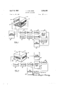
- FIGURE 1 is a perspective view of a cage employed in the apparatus according to the preesnt invention
- FIGURE 2 is a diagram of apparatus according to the present invention employing the cage of FIGURE 1
- FIGURE 3 is a diagram of apparatus according to the present invention also employing the cage of FIGURE 1
- FIGURE 4 is a block diagram of apparatus according to the present invention employing a different cage to that shown in FIGURE 1
- FIGURE 5 is a block diagram of apparatus according to the invention employing a cot
- FIGURE 6 is a perspective view of a mattress, partly in section, employed with apparatus according to the present invention
- FIGURE 7 is a diagram of apparatus according to the present invention employing the mattress of FIG- URE 6
- FIGURE 8 is a diagram of apparatus according to the present invention employing a chair.
- a cage comprises a lower wall or base 1 which is made of an electrically conductive grid or mesh, and sidewalls 2, 4 and 5 which are made of an electrically insulating material.
- the upper wall 3 may be made either electrically conductive or electrically insulating and has been omitted for the purpose of clarity, the side walls being shown transparent for the same reason.
- a conductive strip 6 and 7 such as metal foil, which may conveniently be attached by means of a suitable adhesive.
- FIGURE 2 The apparatus employed with the cage described above for indicating the position of an animal within the cage of FIGURE 1 is shown in block form in FIGURE 2.
- a small amplitude high frequency sine wave which may conveniently have a frequency of kc./ s. and an amplitude of 2-volts peak to peak is produced in a signal generator 10 and is fed to the top 3 and/or base 1 and also the upper wall 3 if this is made of electrically conducting material of the cage 11 which may house a small animal depicted at 12.
- the animal 12 being in contact with the base 1 thus becomes an additional radiator for the high frequency signal applied to the the base 1 and the high frequency signal will be received by the conductive strips or plates 6 and 7 which act as antennae.
- each antenna The amount of signal re ceived by each antenna will be dependent upon the proximity of the animal to each antanna. Thus, if the animal is nearer to antenna 6 than antenna 7, a greater high frequency signal will be received by antenna 6 than antenna 7.
- the received signals are fed first to tuned receivers 13 and 14 which are capable of rejecting frequencies other than that produced by the signal generator 10, which are then amplified by amplifiers 15 and 16.
- the amplified signals are applied to detectors v17 and 18, detector 17 as sociated with antenna 7 detecting the positive excursions of the received signals whilst detector 18 associated with antenna 6 detects the negative excursions of the received signal.
- the detected signals are smoothed to produce positive and negative D.C.
- FIGURE 3 shows an alternative method of obtaining information from the cage and in this case the number of movements that the animal makes is also recorded.
- the base 1 of the cage is energised from the signal generator 10 and signals received by the two antennae 6 and 7 are again fed successively to receivers 13, 14, amplifiers 15, 16 and detectors 17, 13.
- the outputs from the two detectors are applied to a combined summation and differential unit 21 which has two outputs, one of which being from the summation portion of the unit is applied to the first channel of a pen recorder 23 to produce a plot which again is an indication of the position of the animal within the cage.
- the second output is from the differential portion of the unit 21 and this only produces a shaped output when the change in strength of the signals applied to the unit exceeds a given predetermined level, i.e. the animal moves more than a given amount.
- This shaped output is fed to an electromechanical counter 22 to indicate the total number of movements, and also to the second channel of pen recorder 23 to record each movement (by a stroke in one direction) and also to record every tenth movement (indicated by a stroke in the other direction)
- the cage is not provided with a conductive base, or if it is so provided, the signal generator 10 is not directly connected to it, but to an alternative transmitting means.
- FIGURE 4 One such an arrangement is shown in FIGURE 4 where two adjacent side walls 4 and are provided with conductive plates 24 and 25, though these could be positioned on opposite walls.
- the plate 24 is connected to the signal generator whilst the plate 25, acting as a receiving antenna is connected to the receiver 13, amplifier 15, detector 17 and differential unit 21, counter 22 and pen recorder 23, only one receiving channel being employed in this arrangement.
- antenna 25 With arrangements such as this where the animal does not form part of the radiating element the presence of the animal decreases the amount of signal received by the antenna, in this arrangement antenna 25.
- This single channel system will not be able to give an indication of the position of the animal in the cage but will record the number of movements and activity of the animal due to changes in signal strength received by the antenna 25.
- FIGURE 5 Such an arrangement is shown in FIGURE 5 in which the cot 26 is of the metal framed type as employed in hospitals.
- the signal generator 10 is connected to the frame of the cot and the signals are partially absorbed by a baby (not shown) lying on a mattress 27.
- the mattress is provided with two metallic strips or wires 28 and 29 which are implanted in it and which act as receiving antennae to pick up signals of varying strength depending upon the position and movement of the baby in the cot although in this arrangement the signal strength picked up by an antenna decreases as the baby approaches that antenna.
- the signals are processed in a similar manner to that shown with respect to FIG- URE 3 above to produce a numerical count of movement on the counter 22 and a graphical display of the count and position on the pen recorder 23.
- the cot may be provided with a mattress 30 as shown in FIG. 6.
- This mattress is provided with two implanted metallic conductors or wires 31 and 32 in a similar manner to those contained in mattress 25 shown in FIGURE 5 above, and which act as receiving antennae. Between these two conductors 31 and 32 is implanted a further metallic conductor or wire 33 and it is to this conductor that the signal generator will be connected Whilst the two receiving antennae 31 and 32 are connected as before to the detection system.
- This type of mattress may also be employed on a bed and will be of especial use in hospitals when it is desired to observe the movements of a patient during a post operative period.
- the two receiving antennae 31 and 32 may be connected together and applied to a single channel receiving system as shown in FIGURE 7.
- This single channel receiving system will comprise receiver 13, amplifier 15, detector 17, differentiator 21, counter 22 and pen recorder 23.
- the output direct from the difierentiator to the pen recorder will apply to one channel of the pen recorder a signal equivalent to variations in signal strength received by the antenna. This has been shown to be sensitive enough to show up the respiration rate of the child or person on the mattress.
- a chair 34 which is made substantially of electrically insulating material (i.e. wood) and which has a metallic plate 35 provided under the seat 36 to act as a radiator for the high frequency signal.
- the receiving antennae are formed by conductive strips or wires 37 and 38 positioned under or implanted within the arms 39 and 40. These two antennae may be connected together as were the antennae of FIGURE 7 and connected to the receiving equipment in the same manner, the signal generator 10 being connected to the radiating plate. Processing of the signals received by the antennae will be in a like manner to that disclosed with reference to FIGURE 4 with the two antennae connected together.
- radiator means connected to receive said high frequency signals for transmitting said signals in said predetermined space
- rnezrpafiaars mlaim 1 further comprising, means for generating a shaped output signal whenever any of said circuit outputs exceed a predetermined level
- said recording means includes means for recording the number of shaped outputs.
- At least one receiving antenna spaced from said transmission means in near proximity to said bed,
- a second detecting means connected to said second receiving and amplifying means for producing an output in response to said signals
Description
.wu rmz SR X 3% QR Be t-399.355 3 A ril 15, 1969 T. J. SALMONS 3,439,353
ACTIVITY DETECTORS Filed Nov. 50, 1965 Sheet I of 4 LQ-i RECEIVER AMPLIFIER DETECTOR SUMMATION CIRCUIT RECEIVER AMPLIFIER DETECTOR l4 no INVENTOR SIGNAL PEN Tgrence J Salmons GENERATOR RECORDER O I ATTO R N E vs I0 I 20 film-"nu, q
April 15, 1969 T. J. SALMONS 3,
ACTIVITY DETECTORS Filed Nov. :50, 1965 Sheet 5 of 4 SIGNAL GENERATOR RECEIVER AMPLIFIER DETECTOR COUNTER DIFFEK- PEN m? 22 RECORDER RECEIVER AMPLIFIER DETECTOR II ,1 I] ll [4 I6 l6 2| 23 M INVENTOR Tare. nae J. Salmons ATTOR Nays P 969 T. J. SALMONS 3,439,358
ACTIVITY DETECTORS Filed Nov. 30, 1965 Sheet 4 of 4 j I I a (V 55 FIG. 7 A0 SIGN AL I GENERATOR COUNTER R 1/ ECEEVER AMPLl FIER DETEE'TOR ram/ 1. 22 RECORDER lg l V7 FIG. 8
/IO SIGNAL GENERATOR COUNTER L DIFFER' PEN REOEIIVER AMPLIIFIER DETE(:TOR 5313 22 RECORDER 2| INVEN To R Tercncx. Salmons ATTORNEMS United States Patent 3,439,358 ACTIVITY DETECTORS Terence J. Salmons, Cambridge, England, assignor, by mesne assignments, to George Washington Limited, a corporation of Great Britain Filed Nov. 30, 1965, Ser. No. 510,488 Int. Cl. G081) 13/22 US. Cl. 340-258 9 Claims ABSTRACT OF THE DISCLOSURE This invention relates to devices for detecting and recording movement of animals, both human and non human, within predetermined areas. In one embodiment, the animal itself serves as a source of high frequency radiation. A plurality of receiving antennas develop signals dependent upon their proximity to the animal. A second embodiment provides for the generation of high frequency signals in the area occupied by the animal. Receiving antennas again develop variable outputs, dependent upon movement of the animal in the area. Finally, provision is made for recording movement and counting the number of movements.
This invention relates to an improved method and apparatus for determining the activity or position, generally referred to as the movement of an animal or the like within a predetermined area or space. Such apparatus is already known but it is of a relatively crude nature in that the movement of an animal is indicated for example by the animal energising a micro-switch. Thus the accuracy in determining say the position of an animal is dependent upon the number of micro-switches contained within the enclosed space.
The present invention provides an apparatus for observing the movement of an animal within a predetermined area or space, said apparatus comprising a source of low voltage radio frequency signals, means for energising said animal with radio signals received from said source, at least one receiving antenna about said area or space and adapted to receive said radio frequency signals, and means for indicating variations in signal received in the said antenna depending on a change in position of the said animal within the area or space. The predetermined area or space may be a cage, or where the animal is human it may be a cot, bed or chair. In one construction of cage the upper and/or lower walls may be made electrically conductive and to which the high frequency signal may be applied to energise the animal whilst the side walls may be made electrically insulating and at least two side walls provided with electrically conductive areas acting as receiving antenna. In an alternative construction of a cage where it is only desired to measure activity or respiration rate of the animal, all the walls may be made electrically insulating with two of the side walls provided with electrically conductive areas, one to have the high frequency signal applied thereto, and the other to act as a receiving antennae. Where the predetermined areas is a metal framed cot, the side walls may have the frequency signal applied thereto and the receiving antenna or antennae may be implanted in a mattress provided in the cot. If the cot has a frame made of electrically insulating material the mattress besides supporting the receiving antennae may contain a further element to act as a radiator for the high frequency signal. Such a mattress may also be used on a bed to indicate the movements of a person lying thereon. When the predetermined area is a chair the high frequency may be radiated from a metal plate provided under the seat whilst the receiving antenna may be positioned either on or within the arms of the chair. The sigice nal may be used to operate a pen recorder which will graphically record the position of the animal, or to energise an electromechanical counter to give a visual indication of the number of movements made by the animal.
The above and other features of the invention will be more readily understood by a perusal of the following description having reference to the accompanying drawings in which FIGURE 1 is a perspective view of a cage employed in the apparatus according to the preesnt invention, FIGURE 2 is a diagram of apparatus according to the present invention employing the cage of FIGURE 1, FIGURE 3 is a diagram of apparatus according to the present invention also employing the cage of FIGURE 1, FIGURE 4 is a block diagram of apparatus according to the present invention employing a different cage to that shown in FIGURE 1, FIGURE 5 is a block diagram of apparatus according to the invention employing a cot, FIGURE 6 is a perspective view of a mattress, partly in section, employed with apparatus according to the present invention, FIGURE 7 is a diagram of apparatus according to the present invention employing the mattress of FIG- URE 6 and FIGURE 8 is a diagram of apparatus according to the present invention employing a chair.
Referring to FIGURE 1, a cage comprises a lower wall or base 1 which is made of an electrically conductive grid or mesh, and sidewalls 2, 4 and 5 which are made of an electrically insulating material. The upper wall 3 may be made either electrically conductive or electrically insulating and has been omitted for the purpose of clarity, the side walls being shown transparent for the same reason. On each of two of the side walls 2 and 4, is provided a conductive strip 6 and 7 such as metal foil, which may conveniently be attached by means of a suitable adhesive.
The apparatus employed with the cage described above for indicating the position of an animal within the cage of FIGURE 1 is shown in block form in FIGURE 2. A small amplitude high frequency sine wave which may conveniently have a frequency of kc./ s. and an amplitude of 2-volts peak to peak is produced in a signal generator 10 and is fed to the top 3 and/or base 1 and also the upper wall 3 if this is made of electrically conducting material of the cage 11 which may house a small animal depicted at 12. The animal 12 being in contact with the base 1 thus becomes an additional radiator for the high frequency signal applied to the the base 1 and the high frequency signal will be received by the conductive strips or plates 6 and 7 which act as antennae. The amount of signal re ceived by each antenna will be dependent upon the proximity of the animal to each antanna. Thus, if the animal is nearer to antenna 6 than antenna 7, a greater high frequency signal will be received by antenna 6 than antenna 7. The received signals are fed first to tuned receivers 13 and 14 which are capable of rejecting frequencies other than that produced by the signal generator 10, which are then amplified by amplifiers 15 and 16. The amplified signals are applied to detectors v17 and 18, detector 17 as sociated with antenna 7 detecting the positive excursions of the received signals whilst detector 18 associated with antenna 6 detects the negative excursions of the received signal. The detected signals are smoothed to produce positive and negative D.C. voltages respectively and applied to a summation circuit 19 to produce an output which may vary in a positive or negative manner about zero. This output is applied to a pen-recorder 20 employing a centre reading ammeter and the plot produced will thus be an indication of the position of the animal in the cage.
FIGURE 3 shows an alternative method of obtaining information from the cage and in this case the number of movements that the animal makes is also recorded. As in FIGURE 2, the base 1 of the cage is energised from the signal generator 10 and signals received by the two antennae 6 and 7 are again fed successively to receivers 13, 14, amplifiers 15, 16 and detectors 17, 13. The outputs from the two detectors are applied to a combined summation and differential unit 21 which has two outputs, one of which being from the summation portion of the unit is applied to the first channel of a pen recorder 23 to produce a plot which again is an indication of the position of the animal within the cage. The second output is from the differential portion of the unit 21 and this only produces a shaped output when the change in strength of the signals applied to the unit exceeds a given predetermined level, i.e. the animal moves more than a given amount. This shaped output is fed to an electromechanical counter 22 to indicate the total number of movements, and also to the second channel of pen recorder 23 to record each movement (by a stroke in one direction) and also to record every tenth movement (indicated by a stroke in the other direction) In alternative arrangements to those described above the cage is not provided with a conductive base, or if it is so provided, the signal generator 10 is not directly connected to it, but to an alternative transmitting means. One such an arrangement is shown in FIGURE 4 where two adjacent side walls 4 and are provided with conductive plates 24 and 25, though these could be positioned on opposite walls. The plate 24 is connected to the signal generator whilst the plate 25, acting as a receiving antenna is connected to the receiver 13, amplifier 15, detector 17 and differential unit 21, counter 22 and pen recorder 23, only one receiving channel being employed in this arrangement. With arrangements such as this where the animal does not form part of the radiating element the presence of the animal decreases the amount of signal received by the antenna, in this arrangement antenna 25. This single channel system will not be able to give an indication of the position of the animal in the cage but will record the number of movements and activity of the animal due to changes in signal strength received by the antenna 25.
So far the present invention has been described with reference to a cage but it is not limited thereto as it may also be applied to a cot to record the movements of a baby or young child. Such an arrangement is shown in FIGURE 5 in which the cot 26 is of the metal framed type as employed in hospitals. The signal generator 10 is connected to the frame of the cot and the signals are partially absorbed by a baby (not shown) lying on a mattress 27. The mattress is provided with two metallic strips or wires 28 and 29 which are implanted in it and which act as receiving antennae to pick up signals of varying strength depending upon the position and movement of the baby in the cot although in this arrangement the signal strength picked up by an antenna decreases as the baby approaches that antenna. The signals are processed in a similar manner to that shown with respect to FIG- URE 3 above to produce a numerical count of movement on the counter 22 and a graphical display of the count and position on the pen recorder 23.
Where the cot is not of the metal framed type but made of electrically insulating material such as wood it is not possible to radiate the signal from the cot frame. In such a case the cot may be provided with a mattress 30 as shown in FIG. 6. This mattress is provided with two implanted metallic conductors or wires 31 and 32 in a similar manner to those contained in mattress 25 shown in FIGURE 5 above, and which act as receiving antennae. Between these two conductors 31 and 32 is implanted a further metallic conductor or wire 33 and it is to this conductor that the signal generator will be connected Whilst the two receiving antennae 31 and 32 are connected as before to the detection system. This type of mattress may also be employed on a bed and will be of especial use in hospitals when it is desired to observe the movements of a patient during a post operative period.
With a bed or cot employing a mattress 0f the type described with reference to FIGURE 6 and where it is desired only to measure the number of movements made rather than indicate the position that the child or person is in; the two receiving antennae 31 and 32 may be connected together and applied to a single channel receiving system as shown in FIGURE 7. This single channel receiving system will comprise receiver 13, amplifier 15, detector 17, differentiator 21, counter 22 and pen recorder 23. The output direct from the difierentiator to the pen recorder will apply to one channel of the pen recorder a signal equivalent to variations in signal strength received by the antenna. This has been shown to be sensitive enough to show up the respiration rate of the child or person on the mattress.
In an alternative arrangement shown in FIGURE 8 where it is desired to observe the reaction of a person while sitting, a chair 34 is provided which is made substantially of electrically insulating material (i.e. wood) and which has a metallic plate 35 provided under the seat 36 to act as a radiator for the high frequency signal. The receiving antennae are formed by conductive strips or wires 37 and 38 positioned under or implanted within the arms 39 and 40. These two antennae may be connected together as were the antennae of FIGURE 7 and connected to the receiving equipment in the same manner, the signal generator 10 being connected to the radiating plate. Processing of the signals received by the antennae will be in a like manner to that disclosed with reference to FIGURE 4 with the two antennae connected together.
I claim:
1. In an apparatus for automatically detecting movement of an animal, human or non-human, within a predetermined space, the combination comprising,
means for generating high frequency electrical signals,
radiator means connected to receive said high frequency signals for transmitting said signals in said predetermined space,
a plurality of spaced receiving means for receiving said transmitted signals,
a plurality of electrical circuit means, a circuit connected to each of said receiving means for developing an output dependent upon the proximity of said animal to its associated receiving means,
means connected to receive said circuit outputs for generating a signal corresponding to the sum of said signals,
and recording means connected to receive said sum signal for graphically reproducing the detected movements of said animal.
2. The apparatus of claim 1, wherein said radiator means includes said animal.
3. rnezrpafiaars mlaim 1, further comprising, means for generating a shaped output signal whenever any of said circuit outputs exceed a predetermined level,
means for counting the number of shaped outputs,
and, wherein said recording means includes means for recording the number of shaped outputs.
4. In an apparatus for observing the movements of an animal or person on a bed on which a mattress is provided, the combination comprising a signal generator producing radio frequency signals and connected to transmission means in near proximity to said bed,
at least one receiving antenna spaced from said transmission means in near proximity to said bed,
signal receiving and amplifying means connected to said receiving antenna,
detecting means connected to said receiving and amplifying means for producing an output in response to said signals,
and signal utilization means connected to receive the output of said detecting means for indicgtipg g ria; h naig Ql did outp 5. The apparatus of claim 4, in which said bed has a metal frame, said frame constituting said transmission means.
6. The apparatus of claim 5, in which a second receiving antenna is located in near proximity to said bed,
a second signal receiving and amplifying means connected to said second receiving antenna,
a second detecting means connected to said second receiving and amplifying means for producing an output in response to said signals,
the output of said second detecting means also being coupled to said signal utilization means.
7. The apparatus of claim 6 in which said detecting means produces an output of opposite polarity to that produced by said second detecting means.
8. The apparatus of claim 6, in which said signal utilization means also provides a readgwhich is a function of the instantaneous position of the animal.
9. The apparatus of claim 4, in which said transmission means is an antenna planted in said mattress.
6 References Cited FOREIGN PATENTS 7/ 1953 Germany. 2/1930 France. 2/ 1948 France.
JOHN W. CALDWELL, Primary Examiner.
D. L. TRAFTON, Assistant Examiner.
US. Cl. X.R.
Applications Claiming Priority (1)
| Application Number | Priority Date | Filing Date | Title |
|---|---|---|---|
| US51048865A | 1965-11-30 | 1965-11-30 |
Publications (1)
| Publication Number | Publication Date |
|---|---|
| US3439358A true US3439358A (en) | 1969-04-15 |
Family
ID=24030946
Family Applications (1)
| Application Number | Title | Priority Date | Filing Date |
|---|---|---|---|
| US510488A Expired - Lifetime US3439358A (en) | 1965-11-30 | 1965-11-30 | Activity detectors |
Country Status (1)
| Country | Link |
|---|---|
| US (1) | US3439358A (en) |
Cited By (55)
| Publication number | Priority date | Publication date | Assignee | Title |
|---|---|---|---|---|
| US3533095A (en) * | 1969-01-02 | 1970-10-06 | James Collins | Inflatable pad with alarm |
| US3633001A (en) * | 1969-11-05 | 1972-01-04 | Bel Art Products | Apparatus for measuring the activity of laboratory animals |
| US3638642A (en) * | 1970-03-13 | 1972-02-01 | Teledoc Corp | Patient monitoring system with bedsheet-mounted antenna |
| US3656474A (en) * | 1969-08-22 | 1972-04-18 | Philip Morris Inc | Method and apparatus for medical diagnosis |
| US3693590A (en) * | 1971-04-21 | 1972-09-26 | Bowers Instr Co | Animal conditioned avoidance apparatus |
| US3727181A (en) * | 1972-01-31 | 1973-04-10 | Gen Motors Corp | Vehicle seat occupant sensor |
| US3727606A (en) * | 1970-06-12 | 1973-04-17 | Airco Inc | Apnea detection device |
| US3732538A (en) * | 1972-02-23 | 1973-05-08 | Gen Motors Corp | Electronic vehicle seat occupant sensor |
| US3740567A (en) * | 1972-04-20 | 1973-06-19 | Wagner Electric Corp | High-discrimination antenna array for capacitance-responsive circuits |
| US3796208A (en) * | 1971-09-07 | 1974-03-12 | Memco Ltd | Movement monitoring apparatus |
| US3806867A (en) * | 1971-06-04 | 1974-04-23 | Lectron Products | Method and apparatus for detecting the utilization of a vehicle safety belt |
| US3875929A (en) * | 1972-07-25 | 1975-04-08 | Peak Technologies Ltd | Patient movement monitoring apparatus |
| US3921621A (en) * | 1973-08-23 | 1975-11-25 | Lee R Baessler | Method and system utilizing a disposable transmitter for monitoring a patient{3 s condition |
| US3938500A (en) * | 1974-08-19 | 1976-02-17 | The Board Of Trustees Of Leland Stanford Junior University | Automated newborn hearing screening apparatus and method |
| US3974798A (en) * | 1975-04-21 | 1976-08-17 | Meetze Jr Murray O | Method and apparatus for studying laboratory animal behavior |
| US3991746A (en) * | 1975-03-31 | 1976-11-16 | Medical R & D, Limited | Patient monitoring system and method |
| US4070616A (en) * | 1975-05-22 | 1978-01-24 | Kristinsson Bjoern | Method and apparatus for detecting fish in water |
| US4112926A (en) * | 1976-12-08 | 1978-09-12 | The Children's Memorial Hospital | Method and apparatus for measuring and treating hyperactivity in human beings |
| US4165458A (en) * | 1976-04-23 | 1979-08-21 | Mitsubishi Denki Kabushiki Kaisha | Signal decision system |
| US4197855A (en) * | 1977-04-04 | 1980-04-15 | Siemens Aktiengesellschaft | Device for measuring the location, the attitude and/or the change in location or, respectively, attitude of a rigid body in space |
| US4213122A (en) * | 1978-08-23 | 1980-07-15 | The United States Of America As Represented By The Secretary Of The Air Force | Intrusion detection system |
| US4242672A (en) * | 1977-11-09 | 1980-12-30 | Gault Robert L | Patient monitoring system and switch |
| US4279257A (en) * | 1977-03-31 | 1981-07-21 | Hochstein Peter A | Electromagnetic field responder for respiration monitoring |
| US4303077A (en) * | 1978-04-04 | 1981-12-01 | Siemens Aktiengesellschaft | Device for the measurement of the location, the position and/or the change of location or of position of a rigid body in space |
| US4326197A (en) * | 1979-03-28 | 1982-04-20 | Societe Logilift S.A.R.L. | Proximity detector |
| US4329571A (en) * | 1979-04-17 | 1982-05-11 | Gerig John S | Counting with plural electric fields |
| US4337726A (en) * | 1980-07-07 | 1982-07-06 | Czekajewski Jan A | Animal activity monitor and behavior processor |
| US4346427A (en) * | 1979-06-29 | 1982-08-24 | Robert Rothenhaus | Control device responsive to infrared radiation |
| US4371836A (en) * | 1978-12-06 | 1983-02-01 | Siemens Aktiengesellschaft | Device for measuring the location, attitude and/or change of location or, respectively attitude of a rigid body in space utilizing two sets of four parallel antennas for concentrating the field lines |
| US4468795A (en) * | 1979-04-17 | 1984-08-28 | Gerig John S | Counting method and apparatus |
| US4631477A (en) * | 1983-08-01 | 1986-12-23 | Siemens Aktiengesellschaft | Method for eliminating spurious signals in a measuring installation for identifying the position of a rigid body in space |
| US4794549A (en) * | 1986-09-19 | 1988-12-27 | The United States Of America As Represented By The Secretary Of The Army | Excito-repellency test system |
| DE3916500A1 (en) * | 1989-05-20 | 1990-11-22 | Eberhard Zech | METHOD FOR DETERMINING THE MOVEMENT PROCESS OF AN OBJECT, IN PARTICULAR AN OBJECT IN A ROOM |
| US5025796A (en) * | 1988-12-01 | 1991-06-25 | The United States Of America As Represented By The Department Of Health And Human Services | Apparatus and methods for determining in vivo response to thermal stimulation in in an unrestrained subject |
| US5140309A (en) * | 1991-03-12 | 1992-08-18 | Gaymar Industries, Inc. | Bed signalling apparatus |
| US5184112A (en) * | 1991-09-11 | 1993-02-02 | Gaymar Industries, Inc. | Bed patient position monitor |
| US5510766A (en) * | 1992-09-11 | 1996-04-23 | Auratek Security Inc. | Intrusion detection system |
| US6283504B1 (en) | 1998-12-30 | 2001-09-04 | Automotive Systems Laboratory, Inc. | Occupant sensor |
| US20010045733A1 (en) * | 2000-05-26 | 2001-11-29 | Stanley James Gregory | Occupant sensor |
| US6348862B1 (en) | 1999-03-05 | 2002-02-19 | Automotive Systems Laboratory, Inc. | Proximity sensor |
| US6378900B1 (en) | 1999-05-11 | 2002-04-30 | Automotive Systems Laboratory, Inc. | Occupant detection system |
| US6392542B1 (en) | 1999-07-12 | 2002-05-21 | Automotive Systems Laboratory, Inc. | Occupant sensor |
| US6412441B1 (en) * | 2001-01-25 | 2002-07-02 | Med Associates Inc. | Experimental cage having a quick change floor and waste collection assembly and contact points removable for cleaning |
| US6445294B1 (en) | 1999-07-15 | 2002-09-03 | Automotive Systems Laboratory, Inc. | Proximity sensor |
| US20030083795A1 (en) * | 2001-10-31 | 2003-05-01 | Automotive Systems Laboratory, Inc. | Occupant detection system |
| US6825765B2 (en) | 1998-12-30 | 2004-11-30 | Automotive Systems Laboratory, Inc. | Occupant detection system |
| US20060028350A1 (en) * | 2004-08-09 | 2006-02-09 | Bhai Aziz A | Apparatus and method for monitoring a patient in a hospital bed |
| US20060264785A1 (en) * | 2005-05-19 | 2006-11-23 | Barton Dring | Monitoring systems and methods |
| US20070236356A1 (en) * | 2006-03-29 | 2007-10-11 | Jingxi Zhang | Method and apparatus for tracking a laboratory animal location and movement |
| US20080090215A1 (en) * | 2006-09-28 | 2008-04-17 | Clair Mary A | Baby schedule tracker and storage device |
| US20080090216A1 (en) * | 2006-09-28 | 2008-04-17 | Clair Mary A | Baby schedule tracker and storage device |
| US20080106421A1 (en) * | 2006-11-06 | 2008-05-08 | Adams Jerad D | Infant sleep position monitoring system and method |
| US8717181B2 (en) | 2010-07-29 | 2014-05-06 | Hill-Rom Services, Inc. | Bed exit alert silence with automatic re-enable |
| US20170111128A1 (en) * | 2015-10-15 | 2017-04-20 | Infineon Technologies Ag | Localization System and Animal Cage Comprising the Same |
| US10292605B2 (en) | 2012-11-15 | 2019-05-21 | Hill-Rom Services, Inc. | Bed load cell based physiological sensing systems and methods |
Citations (8)
| Publication number | Priority date | Publication date | Assignee | Title |
|---|---|---|---|---|
| FR675049A (en) * | 1929-05-14 | 1930-02-05 | Pile Hydra | Simple device making it possible to record the approach, passage or contact of an object or an animated being and applicable in particular to advertising as well as to protection against theft |
| FR930976A (en) * | 1946-04-26 | 1948-02-10 | Electromagnetic signaling device | |
| DE882061C (en) * | 1951-06-01 | 1953-07-06 | Normalzeit G M B H | Room protection system |
| US3111608A (en) * | 1961-02-27 | 1963-11-19 | Walter G Finch | Contact switch device |
| US3177481A (en) * | 1961-08-10 | 1965-04-06 | More | Electronic alertness control |
| US3237105A (en) * | 1962-05-09 | 1966-02-22 | Henry P Kalmus | Personnel intrusion detecting device |
| US3300768A (en) * | 1963-08-20 | 1967-01-24 | Boeing Co | Radiant energy type intrusion alarm system |
| US3324848A (en) * | 1964-01-10 | 1967-06-13 | Domeier Edward | Capacitance respirometer |
-
1965
- 1965-11-30 US US510488A patent/US3439358A/en not_active Expired - Lifetime
Patent Citations (8)
| Publication number | Priority date | Publication date | Assignee | Title |
|---|---|---|---|---|
| FR675049A (en) * | 1929-05-14 | 1930-02-05 | Pile Hydra | Simple device making it possible to record the approach, passage or contact of an object or an animated being and applicable in particular to advertising as well as to protection against theft |
| FR930976A (en) * | 1946-04-26 | 1948-02-10 | Electromagnetic signaling device | |
| DE882061C (en) * | 1951-06-01 | 1953-07-06 | Normalzeit G M B H | Room protection system |
| US3111608A (en) * | 1961-02-27 | 1963-11-19 | Walter G Finch | Contact switch device |
| US3177481A (en) * | 1961-08-10 | 1965-04-06 | More | Electronic alertness control |
| US3237105A (en) * | 1962-05-09 | 1966-02-22 | Henry P Kalmus | Personnel intrusion detecting device |
| US3300768A (en) * | 1963-08-20 | 1967-01-24 | Boeing Co | Radiant energy type intrusion alarm system |
| US3324848A (en) * | 1964-01-10 | 1967-06-13 | Domeier Edward | Capacitance respirometer |
Cited By (73)
| Publication number | Priority date | Publication date | Assignee | Title |
|---|---|---|---|---|
| US3533095A (en) * | 1969-01-02 | 1970-10-06 | James Collins | Inflatable pad with alarm |
| US3656474A (en) * | 1969-08-22 | 1972-04-18 | Philip Morris Inc | Method and apparatus for medical diagnosis |
| US3633001A (en) * | 1969-11-05 | 1972-01-04 | Bel Art Products | Apparatus for measuring the activity of laboratory animals |
| US3638642A (en) * | 1970-03-13 | 1972-02-01 | Teledoc Corp | Patient monitoring system with bedsheet-mounted antenna |
| US3727606A (en) * | 1970-06-12 | 1973-04-17 | Airco Inc | Apnea detection device |
| US3693590A (en) * | 1971-04-21 | 1972-09-26 | Bowers Instr Co | Animal conditioned avoidance apparatus |
| US3806867A (en) * | 1971-06-04 | 1974-04-23 | Lectron Products | Method and apparatus for detecting the utilization of a vehicle safety belt |
| US3796208A (en) * | 1971-09-07 | 1974-03-12 | Memco Ltd | Movement monitoring apparatus |
| US3727181A (en) * | 1972-01-31 | 1973-04-10 | Gen Motors Corp | Vehicle seat occupant sensor |
| US3732538A (en) * | 1972-02-23 | 1973-05-08 | Gen Motors Corp | Electronic vehicle seat occupant sensor |
| US3740567A (en) * | 1972-04-20 | 1973-06-19 | Wagner Electric Corp | High-discrimination antenna array for capacitance-responsive circuits |
| US3875929A (en) * | 1972-07-25 | 1975-04-08 | Peak Technologies Ltd | Patient movement monitoring apparatus |
| US3921621A (en) * | 1973-08-23 | 1975-11-25 | Lee R Baessler | Method and system utilizing a disposable transmitter for monitoring a patient{3 s condition |
| US3938500A (en) * | 1974-08-19 | 1976-02-17 | The Board Of Trustees Of Leland Stanford Junior University | Automated newborn hearing screening apparatus and method |
| US3991746A (en) * | 1975-03-31 | 1976-11-16 | Medical R & D, Limited | Patient monitoring system and method |
| US3974798A (en) * | 1975-04-21 | 1976-08-17 | Meetze Jr Murray O | Method and apparatus for studying laboratory animal behavior |
| US4070616A (en) * | 1975-05-22 | 1978-01-24 | Kristinsson Bjoern | Method and apparatus for detecting fish in water |
| US4165458A (en) * | 1976-04-23 | 1979-08-21 | Mitsubishi Denki Kabushiki Kaisha | Signal decision system |
| US4112926A (en) * | 1976-12-08 | 1978-09-12 | The Children's Memorial Hospital | Method and apparatus for measuring and treating hyperactivity in human beings |
| US4279257A (en) * | 1977-03-31 | 1981-07-21 | Hochstein Peter A | Electromagnetic field responder for respiration monitoring |
| US4197855A (en) * | 1977-04-04 | 1980-04-15 | Siemens Aktiengesellschaft | Device for measuring the location, the attitude and/or the change in location or, respectively, attitude of a rigid body in space |
| US4242672A (en) * | 1977-11-09 | 1980-12-30 | Gault Robert L | Patient monitoring system and switch |
| US4303077A (en) * | 1978-04-04 | 1981-12-01 | Siemens Aktiengesellschaft | Device for the measurement of the location, the position and/or the change of location or of position of a rigid body in space |
| US4213122A (en) * | 1978-08-23 | 1980-07-15 | The United States Of America As Represented By The Secretary Of The Air Force | Intrusion detection system |
| US4371836A (en) * | 1978-12-06 | 1983-02-01 | Siemens Aktiengesellschaft | Device for measuring the location, attitude and/or change of location or, respectively attitude of a rigid body in space utilizing two sets of four parallel antennas for concentrating the field lines |
| US4326197A (en) * | 1979-03-28 | 1982-04-20 | Societe Logilift S.A.R.L. | Proximity detector |
| US4468795A (en) * | 1979-04-17 | 1984-08-28 | Gerig John S | Counting method and apparatus |
| US4329571A (en) * | 1979-04-17 | 1982-05-11 | Gerig John S | Counting with plural electric fields |
| US4346427A (en) * | 1979-06-29 | 1982-08-24 | Robert Rothenhaus | Control device responsive to infrared radiation |
| US4337726A (en) * | 1980-07-07 | 1982-07-06 | Czekajewski Jan A | Animal activity monitor and behavior processor |
| US4631477A (en) * | 1983-08-01 | 1986-12-23 | Siemens Aktiengesellschaft | Method for eliminating spurious signals in a measuring installation for identifying the position of a rigid body in space |
| US4794549A (en) * | 1986-09-19 | 1988-12-27 | The United States Of America As Represented By The Secretary Of The Army | Excito-repellency test system |
| US5025796A (en) * | 1988-12-01 | 1991-06-25 | The United States Of America As Represented By The Department Of Health And Human Services | Apparatus and methods for determining in vivo response to thermal stimulation in in an unrestrained subject |
| US5345943A (en) * | 1988-12-01 | 1994-09-13 | The United States Of America As Represented By The Secretary Of The Department Of Health And Human Services | Apparatus for determining in vivo response to thermal stimulation in an unrestrained subject |
| DE3916500A1 (en) * | 1989-05-20 | 1990-11-22 | Eberhard Zech | METHOD FOR DETERMINING THE MOVEMENT PROCESS OF AN OBJECT, IN PARTICULAR AN OBJECT IN A ROOM |
| WO1990014603A1 (en) * | 1989-05-20 | 1990-11-29 | Eberhard Zech | Process and device for determining the dynamic profile of an object |
| US5140309A (en) * | 1991-03-12 | 1992-08-18 | Gaymar Industries, Inc. | Bed signalling apparatus |
| US5184112A (en) * | 1991-09-11 | 1993-02-02 | Gaymar Industries, Inc. | Bed patient position monitor |
| US5510766A (en) * | 1992-09-11 | 1996-04-23 | Auratek Security Inc. | Intrusion detection system |
| US6563231B1 (en) | 1998-12-30 | 2003-05-13 | Automotive Systems Laboratory, Inc. | Occupant sensor |
| US6283504B1 (en) | 1998-12-30 | 2001-09-04 | Automotive Systems Laboratory, Inc. | Occupant sensor |
| US6825765B2 (en) | 1998-12-30 | 2004-11-30 | Automotive Systems Laboratory, Inc. | Occupant detection system |
| US6517106B1 (en) | 1998-12-30 | 2003-02-11 | Automotive Systems Laboratory, Inc. | Occupant detection system |
| US6520535B1 (en) | 1998-12-30 | 2003-02-18 | Automotive Systems Laboratory, Inc. | Occupant detection system |
| US6577023B1 (en) | 1998-12-30 | 2003-06-10 | Automotive Systems Laboratory, Inc. | Occupant detection system |
| US6348862B1 (en) | 1999-03-05 | 2002-02-19 | Automotive Systems Laboratory, Inc. | Proximity sensor |
| US6378900B1 (en) | 1999-05-11 | 2002-04-30 | Automotive Systems Laboratory, Inc. | Occupant detection system |
| US6392542B1 (en) | 1999-07-12 | 2002-05-21 | Automotive Systems Laboratory, Inc. | Occupant sensor |
| US6445294B1 (en) | 1999-07-15 | 2002-09-03 | Automotive Systems Laboratory, Inc. | Proximity sensor |
| US7098674B2 (en) | 2000-05-26 | 2006-08-29 | Automotive Systems Laboratory, Inc. | Occupant sensor |
| US6703845B2 (en) | 2000-05-26 | 2004-03-09 | Automotive Systems Laboratory, Inc. | Occupant sensor |
| US20040113634A1 (en) * | 2000-05-26 | 2004-06-17 | Automotive Systems Laboratory, Inc. | Occupant sensor |
| US20010045733A1 (en) * | 2000-05-26 | 2001-11-29 | Stanley James Gregory | Occupant sensor |
| US6412441B1 (en) * | 2001-01-25 | 2002-07-02 | Med Associates Inc. | Experimental cage having a quick change floor and waste collection assembly and contact points removable for cleaning |
| US20030083795A1 (en) * | 2001-10-31 | 2003-05-01 | Automotive Systems Laboratory, Inc. | Occupant detection system |
| US20070268147A1 (en) * | 2004-08-09 | 2007-11-22 | Hill-Rom Services, Inc. | Load-cell based hospital bed control |
| US20060028350A1 (en) * | 2004-08-09 | 2006-02-09 | Bhai Aziz A | Apparatus and method for monitoring a patient in a hospital bed |
| US7253366B2 (en) | 2004-08-09 | 2007-08-07 | Hill-Rom Services, Inc. | Exit alarm for a hospital bed triggered by individual load cell weight readings exceeding a predetermined threshold |
| US7437787B2 (en) | 2004-08-09 | 2008-10-21 | Hill-Rom Services, Inc. | Load-cell based hospital bed control |
| US7541935B2 (en) | 2005-05-19 | 2009-06-02 | Proacticare Llc | System and methods for monitoring caregiver performance |
| US8564445B2 (en) | 2005-05-19 | 2013-10-22 | Proacticare Llc | System and methods for monitoring caregiver performance |
| US8154413B2 (en) | 2005-05-19 | 2012-04-10 | Proacticare Llc | System and methods for monitoring caregiver performance |
| USRE42614E1 (en) | 2005-05-19 | 2011-08-16 | Proacticare Llc | System and methods for monitoring caregiver performance |
| US20100057543A1 (en) * | 2005-05-19 | 2010-03-04 | Barton Dring | System and methods for monitoring caregiver performance |
| US20060264785A1 (en) * | 2005-05-19 | 2006-11-23 | Barton Dring | Monitoring systems and methods |
| US20070236356A1 (en) * | 2006-03-29 | 2007-10-11 | Jingxi Zhang | Method and apparatus for tracking a laboratory animal location and movement |
| US7389744B2 (en) | 2006-03-29 | 2008-06-24 | Jingxi Zhang | Method and apparatus for tracking a laboratory animal location and movement |
| US20080090216A1 (en) * | 2006-09-28 | 2008-04-17 | Clair Mary A | Baby schedule tracker and storage device |
| US20080090215A1 (en) * | 2006-09-28 | 2008-04-17 | Clair Mary A | Baby schedule tracker and storage device |
| US20080106421A1 (en) * | 2006-11-06 | 2008-05-08 | Adams Jerad D | Infant sleep position monitoring system and method |
| US8717181B2 (en) | 2010-07-29 | 2014-05-06 | Hill-Rom Services, Inc. | Bed exit alert silence with automatic re-enable |
| US10292605B2 (en) | 2012-11-15 | 2019-05-21 | Hill-Rom Services, Inc. | Bed load cell based physiological sensing systems and methods |
| US20170111128A1 (en) * | 2015-10-15 | 2017-04-20 | Infineon Technologies Ag | Localization System and Animal Cage Comprising the Same |
Similar Documents
| Publication | Publication Date | Title |
|---|---|---|
| US3439358A (en) | Activity detectors | |
| JP3662247B2 (en) | Surface position selection system and method | |
| CN105556949B (en) | Digital radiography detector image readout | |
| US5170172A (en) | Electronic assembly for range finding using radio wave signal strength | |
| US3540413A (en) | Apparatus for studying the behaviour of laboratory animals | |
| US3638642A (en) | Patient monitoring system with bedsheet-mounted antenna | |
| CN108209863B (en) | Non-wearable sleeping posture monitoring device and bedding thereof | |
| GB2160735A (en) | Direction of lightning ground strikes | |
| US3925610A (en) | Graphic communications tablet | |
| DE3064316D1 (en) | Electromagnetic radiation detector array and x-ray image amplifier comprising such an array | |
| GB1469677A (en) | Position sensitive device | |
| CN208013385U (en) | A kind of photoelectric detection system of lithium battery bulge | |
| US4489313A (en) | Signal direction determining system and directional loop antenna array therefor | |
| IL51642A (en) | Two-dimensional x-ray detector array | |
| IL86305A (en) | Device for slit radiography with image equalization | |
| US3052232A (en) | Voltage sensing apparatus | |
| US3107664A (en) | Medical transducer for detecting arterial pulsations | |
| CA2293475C (en) | Meteorological electromagnetic measuring system | |
| US2509700A (en) | Radioactivity measuring device | |
| JPS54121093A (en) | Microwave device | |
| US3555529A (en) | Apparatus for measuring electric field radiation from living bodies | |
| CN212729795U (en) | Narrow-beam microstrip Doppler radar organism motion detector | |
| Hambrecht | Multi-channel telemetry systems | |
| Clarke | Magnetotelluric measurements | |
| Pfister et al. | A multipurpose activity platform utilized in the open-field setting |