US3441231A - Textile winding machine - Google Patents
Textile winding machine Download PDFInfo
- Publication number
- US3441231A US3441231A US629248A US3441231DA US3441231A US 3441231 A US3441231 A US 3441231A US 629248 A US629248 A US 629248A US 3441231D A US3441231D A US 3441231DA US 3441231 A US3441231 A US 3441231A
- Authority
- US
- United States
- Prior art keywords
- traverse
- shaft
- winding machine
- plate
- thread
- Prior art date
- Legal status (The legal status is an assumption and is not a legal conclusion. Google has not performed a legal analysis and makes no representation as to the accuracy of the status listed.)
- Expired - Lifetime
Links
Images


Classifications
-
- B—PERFORMING OPERATIONS; TRANSPORTING
- B65—CONVEYING; PACKING; STORING; HANDLING THIN OR FILAMENTARY MATERIAL
- B65H—HANDLING THIN OR FILAMENTARY MATERIAL, e.g. SHEETS, WEBS, CABLES
- B65H54/00—Winding, coiling, or depositing filamentary material
- B65H54/02—Winding and traversing material on to reels, bobbins, tubes, or like package cores or formers
- B65H54/026—Doubling winders, i.e. for winding two or more parallel yarns on a bobbin, e.g. in preparation for twisting or weaving
-
- B—PERFORMING OPERATIONS; TRANSPORTING
- B65—CONVEYING; PACKING; STORING; HANDLING THIN OR FILAMENTARY MATERIAL
- B65H—HANDLING THIN OR FILAMENTARY MATERIAL, e.g. SHEETS, WEBS, CABLES
- B65H54/00—Winding, coiling, or depositing filamentary material
- B65H54/02—Winding and traversing material on to reels, bobbins, tubes, or like package cores or formers
- B65H54/40—Arrangements for rotating packages
- B65H54/46—Package drive drums
- B65H54/48—Grooved drums
-
- B—PERFORMING OPERATIONS; TRANSPORTING
- B65—CONVEYING; PACKING; STORING; HANDLING THIN OR FILAMENTARY MATERIAL
- B65H—HANDLING THIN OR FILAMENTARY MATERIAL, e.g. SHEETS, WEBS, CABLES
- B65H63/00—Warning or safety devices, e.g. automatic fault detectors, stop-motions ; Quality control of the package
- B65H63/02—Warning or safety devices, e.g. automatic fault detectors, stop-motions ; Quality control of the package responsive to reduction in material tension, failure of supply, or breakage, of material
- B65H63/024—Warning or safety devices, e.g. automatic fault detectors, stop-motions ; Quality control of the package responsive to reduction in material tension, failure of supply, or breakage, of material responsive to breakage of materials
- B65H63/036—Warning or safety devices, e.g. automatic fault detectors, stop-motions ; Quality control of the package responsive to reduction in material tension, failure of supply, or breakage, of material responsive to breakage of materials characterised by the combination of the detecting or sensing elements with other devices, e.g. stopping devices for material advancing or winding mechanism
-
- B—PERFORMING OPERATIONS; TRANSPORTING
- B65—CONVEYING; PACKING; STORING; HANDLING THIN OR FILAMENTARY MATERIAL
- B65H—HANDLING THIN OR FILAMENTARY MATERIAL, e.g. SHEETS, WEBS, CABLES
- B65H2701/00—Handled material; Storage means
- B65H2701/30—Handled filamentary material
- B65H2701/31—Textiles threads or artificial strands of filaments
Definitions
- a pivotally mounted Weighted yarn package engages the surface of each traverse.
- Mechanism is provided for stopping the individual traverses at will or auto matically upon the breaking of a single thread of yarn, the mechanism including an electrically actuated clutch device and brake mechanism, allowing each traverse on its common shaft to be run or stopped individually without stopping the shaft for the other traverses.
- the mechanism also permits the traverse to stop after a predetermined size has been reached without damaging the threads that are still attached to the package, that are made by the winder.
- the mechanism also permits an indicating light to go on signalling that the individual traverse has stopped and thus calling the operators attention thereto.
- machines that make cones or parallel packages of yarn or any class of thread that uses grooved traverses or Winders are hired permanently to a shaft driven by a motor.
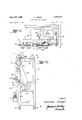
- FIG. 1 is a fragmentary front elevational view of a winding maching embodying the invention, packages being shown in the process of being threaded.
- FIG. 2 is a side elevational view thereof.
- FIG. 3 is a top plan view thereof.
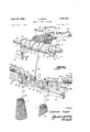
- FIG. 4 is a perspective view partly diagrammatic showing a winder and package assembly, the package being fed from a pair of supply masses, the threads being shown passing through mercury switch mechanisms, the switch mechanisms being shown in inoperative positions.
- FIG. 5 is an enlarged sectional view taken on the plane of the line 5-5 of FIG. 4.
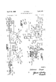
- FIG, 6 is an enlarged top plan view of the mounting 3,441,231 Patented Apr. 29, 1969 for a pair of mercury switches for actuating the clutch and brake mechanisms.
- FIG. 7 is a vertical sectional view taken on the plane of the line 7-7 of FIG. 6.
- FIG. 8 shows a wiring diagram for the electrically actuated clutch and brake mechanisms.
- FIG. 1 shows a fragment of a multiple textile winding machine 10 embodying the invention.
- the machine comprises an open framework, rectangular in plan, including corner front posts 12 of angle bar and rear corner posts 14 of the same material, only one of each corner post being shown.
- the corner posts are mounted on 'casters 15.
- Angle bars 16 and 17 join the front and rear corner posts at the ends of the frame at the top, and bottom, respectively.
- a top angle bar 18 joins the corner posts at the corner posts at the front, and another angle bar 20 joins said front corner posts intermediate the top and bottom ends thereof,
- a third angle bar 22 joins the front corner posts at the bottom.
- An angle bar 24 joins the rear corner posts intermediate the top and bottom ends thereof, angle bar 24 being disposed opposite angle bar 20.
- a drive shaft 30 is journalled at its ends in bearings 32 supported on the'front corner posts 12 adjacent the top ends thereof.
- a plurality of winder or traverse assemblies 34 are loosely mounted on the shaft 30 in spaced relationship therealong.
- Each winder assembly 34 includes, as best seen in FIG. 5, a winder or traverse 36 having a solid cylindrical body 38 of suitable rigid plastic material formed with a spiral groove 40 on its outer surface.
- the body has a central bore 41 extending therethrough.
- a metal bushing 42 is interposed in the bore 41 between the body of the winder and the shaft 30 at each end of the body 38.
- Each bushing is formed with an annular flange 44 outwardly of the adjacent end of the body of the winder and inwardly of its outer free end which flange engages the face of the end of the body.
- Set screws in radial recesses 48 in the body 38 secure the body to the bushings.
- the face of each end of each winder is formed with an annular groove 48'
- a metal disc 50 having a central opening 52 to receive the bushing 42 is fixed to the face of each end inwardly of the groove 48' by means of screws 54.
- An annular metal ring 56 is suitably fixed to the face of the disc 50 along the periphery thereof opposite the groove 48' in the face of the body 38.
- Clutching mechanism indicated generally at 60 is mounted on the shaft 30 adjacent one end of the winder or traverse 36, the right hand end as viewed in FIG. 5, and braking mechanism indicated generally at 61 is mounted on shaft 30 at the other end of the winder or traverse 36.
- the clutching mechanism 60 is closely spaced from the outer end of bushing 40 by means of a washer 62.
- the clutching mechanism is formed with a ring-like body 64 of metal.
- the body 64 comprises a stationary section 66 constituting a stationary clutch field, and a rotating section 68 constituting a rotating clutch field or armature.
- the stationary section 66 is formed with a central bore 69 and with an annular groove 70 in one face thereof, the inner face as viewed in FIG. 5.
- the solenoid 72 is fitted and held in groove '70 protruding slightly outwardly of the face of the body of section 66.
- Section 66 is held against rotation by means of a perforated plate 74 mounted on shaft 30 and fixed to a bracket 76 upstanding from angle bar 18 and fixed thereon.
- the plate 74 constitutes a drag link and may be welded or otherwise suitably fastened to adjacent end face of the body of the fixed section 66.
- the rotating field section 68 comprises a tubular body 80 nested or telescoped in the bore of 69 of stationary section '66.
- the outer end of the body of section 68 extends through the central perforation in plate 74 and is fastened to the shaft by means of a collar 82 on the shaft 30 extending through said perforation.
- a set screw 84 passing through aligned holes in the collar and end of the tubular body of section 68 secures the section 68 to the shaft so that is rotates with the shaft.
- the inner end of tubular body of section 68 is formed with a disc-shaped enlargement 86.
- the disc 86 is formed with an annular groove 88 adjacent the periphery thereof and secured in said groove is a ring 90 of friction material facing and closely spaced from the ring 56 on the end face of the transverse 36 thereby providing an air gap 92.
- Ball bearings 94 are interposed between the fixed and rotating sections in the bore '69 of the fixed section 66 adjacent the outer end of the bore.
- the braking mechanism 61 on the other end of traverse 36 on shaft 30 is somewhat similar to the clutching mechanism 60, being formed with a ring like body 64' having a stationary section 66' with a central bore 69' and with an annular groove 70' in the face thereof, accommodating a solenoid '72 and accommodating a metal ring fitted in the outer end of the groove and extending outwardly of the inner face of the body of the section 66'.
- a friction ring 98' is suitably fastened to the face of the ring 100, closely spaced from the ring 56 on disc 50 secured to the face of the adjacent end of the body 38 of traverse 36 leaving an air gap 92'.
- the fixed section 66' is mounted on a bushing 102 on shaft 30 and is held against movement by a perforated plate 74 on shaft .30 fixed on a bracket 76' secured to the angle bar 18.
- Bushing 102 is spaced from bushing 42 by a washer 62'.
- each holder On the bottom bar or rail 22, there is a plurality of holders for supporting upright unwinding masses M and M of thread, each holder including a plate 136 and a depending pin 138 fitted in a hole in the bar or rail. Above each pair of holders, there is a metal subfr-ame 140 pivotally mounted in end tubular bearings 142 fixed to the bar 20.
- the subframe consists of a plate 144 with tubular end sockets 146 pivotally mounted on pins 148 extending inwardly from the end bearings 142.
- a perforated lug 150 extends upwardly from the rear long edge of the plate as viewed in FIG. 4, adjacent each socket 146.
- the plate is formed with semi-circular enlargements 152 along the front long edge thereof, at each end of the plate.
- Each enlargement is formed with a central recess 154. Seated in each recess, on the base thereof, there is a semi-spherical metal block 155, with a central socket recess 157 in the top surface thereof, and a pin 156 is fitted in the socket 157 and is supported in upright position thereby. Another semi-spherical block 158 is loosely mounted on the pin over the block and mounted on the pin over the block 158 there is a plurality of removable perforated tension discs 160 constructed to open easily.
- the front periphery of each semi-circular enlargement 152 is formed with a narrow notch 162 and with radial fingers 164 extending upwardly and outwardly at an angle.
- the notches 162 are positioned directly above the masses M and M of thread.
- a pair of curved round wires 1'66 and 168 of light stock mounted on the plate between the recess 154 extends upwardly in partially overlapping relation.
- the strands 170 and 172 from masses M and M, respectively, pass upwardly to and through the notches 162, the strands being guided thereinto by the radial fingers 164, 164 if moving out of line, and from the notches, and the strands pass over the blocks 158 in the recesses 154 and under the tension discs 160 thereon and then laterally to the center of the plate 144 where strand 170 of mass M passes loosely around the wire 163 and moves upwardly, and simultaneously, the strand 172 of mass M passes loosely around the wire 166 and then upwardly, in closely spaced relationship to strand 170 to the end of the groove 40 in winder or traverse 36 thereabove, the right hand end, as viewed in FIGS.
- the winding package P of each unit is shown as removably held on a conical shaped spindle 176 mounted on the long arm 178 which is pivoted at 180 to a round rod 182 supported at the rear of the framework between the rear corner posts 14.
- the arm 178 is shown equipped with a weight 184 at its forward end.
- the arm also serves as a handle for manipulating the arm and supported package P.
- the spindle 176 is tapered or conical to cause the package P to be supported so that its conical surface rests on the surface of traverse 36.
- An important feature of the present invention is mechanism for automatically detecting a break in the thread being wound, and for automatically stopping the winding mechanism of each traverse unit separately upon the breaking of a strand or in the case the winding operation has proceeded continuously to complete exhaustion of a supply mass.
- This automatic stopping mechanism is operated electrically using the alternating current supply furnished by the cord 122 and plug 124, by means of conductors and 192.
- the main switch 120 is interposed in conductor 190. Referring to FIG. 8, a direct current rectifier 194 may be connected across the conductors 190 and 192.
- a conductor 196 is connected at one end to the rectifier 194.
- a condenser 206 is connected across the conductors 196 and 198.
- a light bulb 208 is also preferably connected across the conductors 196 and 198.
- a normally closed switch 210 is interposed in conductor 198.
- a conductor 212 is connected to conductor 196 and to the clutching mechanism indicated by coil 213.
- a conductor 214 leads from the clutching mechanism to switch 202.
- a condenser 215 is connected across the conductors 212 and 214.
- Another switch 217 forms part of the relay 200.
- a push button switch 216 is connected to the switch 217 by conductors 218, 220 and 222. Switch 216 is normally open and when the button is pushed the relay is energized.
- a conductor 224 is connected to conductor 218 of switch 216 and a conductor 241 is connected to a transformer 226 connected by conductors 228 and 230, to conductors 190 and 192, respectively.
- a switch 231 is interposed in conductor 224 for manual stopping traverse 36 when running.
- a coil 232, forming part of relay 200, is connected to conductor 222 by a conductor 233 and connected to transformer 226 by a conductor 235.
- a pair of yarn controlled switches 234 and 236 with electrical contacts 237 and 239 is interposed in conductor 224 and are connected to the transformer 226 by conductor 241.
- Switches 234 and 236 are normally open but are closed when yarn is positioned thereover for running as shown in FIG. 4.
- Each switch 234 and 236 comprises a transparent tube 238 closed at both ends with a supply of mercury 240 therein.
- the tubes are mounted at the ends of elongated wires 242 pivotally mounted on pivot pins 244 protruding from the perforated lugs 150 on the ends of the plate 144 at the rear thereof.
- the tubes are held in place by spring clips 243.
- the other ends of the wires are bent at right angles as indicated at 248, and are adapted to extend across the body of plate 144 adjacent the curved wires 166 and 168.
- the weight of the tubes is such that the tubes are adapted to fall by gravity below the plane of the top surface of plate 144 when pressure thereon is released, whereby the mercury in the tubes flows by gravity in one direction to one end of the tubes 238.
- the tubes 238 are normally held on a level keel with the top surface of plate 144, with their bent ends under the threads 170 and 172.
- clutching mechanism 60 and the fields of the braking mechanism 61 cannot be energized at the same time. When either field is energized, it will then draw its respectivearmature towards itself thereby locking up the mechanism. When the shaft 30 is rotating and the clutch mechanism '60 is energized, the traverses 36 will turn at the same speed as the shaft 30. When the brake field is energized the clutching mechanism will be deenergized and will cause the individual traverse to stop its rotation.
- the mercury switch 236 will similarly fall by gravity and will simultaneously deenergize the clutching mechanism 60 and energiie the braking mechanism 61.
- the pressure on the ends 2.48 of the wires 242 are released with similar results.
- the tilting of each mercury switch also closes the circuit through the bulb 208 thereby signalling that the traverse has stopped rotating.
- a framework rectangular in plan, including upstanding corner posts, bars extending the length of the framework at the top and bottom thereof, at the front of the framework, a rod extending the length of the framework at the top thereof, at the rear of the framework and cross bars joining the corner posts at the top and bottom thereof at the ends of the framework, a plurality of pairs of masses of thread removably mounted on the bottom bar of the framework, a rotatable shaft supported on the front end of the top cross bars, a motor for rotating said shaft, means for connecting said motor to a source of electric motive force, a plurality of traverses mounted loosely on the shaft in spaced relationship, means for operatively and releasably connecting said traverses to the shaft, means for guiding the thread from a pair of masses to a single traverse, removable thread packages pivotally connected to the bar at the rear of the framework and adapted to be supported on the traverses for receiving threads in wound condition from the traverses, and automatic means for stopping
- a textile winding machine as defined in claim 1 wherein the pivotal connection between the packages and rear rod includes an elongated arm pivotally connected at one end to the rod, a conical shaped spindle carried at the other end of the arm disposed radially thereof for removably mounting the thread package.
- the automatic means for stopping the winding of the thread includes at least one pivotally mounted mercury switch, said pivotal mounting including an elongated wire pivoted intermediate its ends to the plate, a tube supported at one end of the wire, said tube containing mercury, electrical contacts carried at the ends of the tube, a supply of mercury in said tube adapted to roll into engagement with either of said contacts, when the tube is tilted by gravity, the other end of the wire being bent and disposed across the plate, at least one curved wire disposed upwardly on the plate adjacent the bent end of the wire, said curved wire adapted to receive a thread passing from the notch and over and in pressing contact with the bent end of the wire to keep the tube in even keel with the surface of the plate, said tube being heavier than the bent end of the wire, said tube being electrically and operatively connected to the clutching mechanism associated with the traverse and with the braking mechanism associated with the traverse so that upon breaking of the thread and release of the pressure thereof on the bent end, the
- a textile winding machine as defined in claim 3 wherein the automatic means for stopping the winding of the thread from a pair of masses includes a pivotally mounted mercury switch associated with the thread of each mass, the pivotal mounting of each switch including an elongated wire pivoted intermediate its ends to the plate, a tube supported at one end of the wire, said tube containing mercury, electrical contacts carried at the ends of the tube, a supply of mercury in said tube adapted to roll into engagement with either of said contacts, when the tube is tilted by gravity, the other end of the wire being bent and disposed across the plate, curved wires disposed upwardly on the plate adjacent the bent ends of the wires, said curved wires adapted to receive threads passings from the notch and over and in pressing contact with the bent ends of the wires to keep the tubes in even keel with the surface of the plate, said tubes being heavier than the bent ends of the wires, said tubes being electrically and operatively connected to the clutching mechanism associated with the traverse and with the braking mechanism associated with traverse so that upon
Description
April 29,1969 5,. C-55 3,441,231
' TEXTILE WINDING MACHINE Filed April 7, 1967 Sheet of 5 INVENT OR Solomon Siege/ BY W9 TTURNEYE April 29, 1969 s. SIEGEL 3,441,231
TEXTILE WINDING MACHINE Filed April 7, 1967 Sheet 3 of 5 INVENTOR.
Solomon Sie ge/ BY W ATTDRNEYS April 29, 1969 s. SIEGEL TEXTILE WINDING MACHINE INVENTOR .5 olomon Siege/ Filed April 7, 1967 Apr-i129, 1969 SSIEGEI. 1 3,441,231
TEXTILE WINDING MACHINE,
Filed April 7, 1967 Sheet 4 or 5 INvN'roR Solomon, .SIege/ BY Wm Seas April 29, 1969 s. SIEGEL TEXTILE WINDING MACHINE Sheet 5 0 Filed April 7,- 1967 mmw *NN 3,441,231 TEXTILE WINDING MACHINE Solomon Siege], 13-55 209th St., Bayside, NY. 11360 Filed Apr. 7, 1967, Ser. No. 629,248 Int. Cl. B65h 63/02, 54/00, 59/00 U.S. Cl. 24238 7 Claims ABSTRACT OF THE DISCLOSURE A textile winding machine having a plurality of driven grooved traverses or winders on a common motor driven shaft. A pivotally mounted Weighted yarn package engages the surface of each traverse. Mechanism is provided for stopping the individual traverses at will or auto matically upon the breaking of a single thread of yarn, the mechanism including an electrically actuated clutch device and brake mechanism, allowing each traverse on its common shaft to be run or stopped individually without stopping the shaft for the other traverses. The mechanism also permits the traverse to stop after a predetermined size has been reached without damaging the threads that are still attached to the package, that are made by the winder. The mechanism also permits an indicating light to go on signalling that the individual traverse has stopped and thus calling the operators attention thereto.
At present, machines that make cones or parallel packages of yarn or any class of thread that uses grooved traverses or Winders are hired permanently to a shaft driven by a motor.
The reason for running many traverses on one shaft driven by a single motor is that for a good wind the motor current is shut off after a predetermined time and then switched on again. Normally a small drop in speed of 10 to 25% is allowed to take place before the current goes on again. This causes a slippage between traverse and the cone being made. Because of the controls needed to effect this current cut off and cut in, it is easier to control one motor for a great number of traverses. Usually a plurality of traverses are mounted on single shaft. In making a package from more than one end of yarn, if one of the ends were to run out or break and the package being built is lifted away from the traverse, the remaining end would get tangled up with the fast spinning traverse and cause great deal of damage. In the past, doubling (combining two or more ends on a package) has been found impractical on a winder with a grooved traverse.
It is a principal object of the present invention to provide a mechanism for selectively and automatically stopping individually any grooved traverse on a common drive shaft having a broken thread, allowing such winder to be used for doubling with no danger of damaging itself or the package being made.
Brief description of the views of the drawings FIG. 1 is a fragmentary front elevational view of a winding maching embodying the invention, packages being shown in the process of being threaded.
FIG. 2 is a side elevational view thereof.
FIG. 3 is a top plan view thereof.
FIG. 4 is a perspective view partly diagrammatic showing a winder and package assembly, the package being fed from a pair of supply masses, the threads being shown passing through mercury switch mechanisms, the switch mechanisms being shown in inoperative positions.
FIG. 5 is an enlarged sectional view taken on the plane of the line 5-5 of FIG. 4.
FIG, 6 is an enlarged top plan view of the mounting 3,441,231 Patented Apr. 29, 1969 for a pair of mercury switches for actuating the clutch and brake mechanisms.
FIG. 7 is a vertical sectional view taken on the plane of the line 7-7 of FIG. 6.
FIG. 8 shows a wiring diagram for the electrically actuated clutch and brake mechanisms.
Detailed description of the drawings Referring now in detail to the various views of the drawings, FIG. 1 shows a fragment of a multiple textile winding machine 10 embodying the invention. The machine comprises an open framework, rectangular in plan, including corner front posts 12 of angle bar and rear corner posts 14 of the same material, only one of each corner post being shown. The corner posts are mounted on 'casters 15. Angle bars 16 and 17 join the front and rear corner posts at the ends of the frame at the top, and bottom, respectively. A top angle bar 18 joins the corner posts at the corner posts at the front, and another angle bar 20 joins said front corner posts intermediate the top and bottom ends thereof, A third angle bar 22 joins the front corner posts at the bottom. An angle bar 24 joins the rear corner posts intermediate the top and bottom ends thereof, angle bar 24 being disposed opposite angle bar 20.
In accordance with the present invention, a drive shaft 30 is journalled at its ends in bearings 32 supported on the'front corner posts 12 adjacent the top ends thereof. A plurality of winder or traverse assemblies 34 are loosely mounted on the shaft 30 in spaced relationship therealong. Each winder assembly 34 includes, as best seen in FIG. 5, a winder or traverse 36 having a solid cylindrical body 38 of suitable rigid plastic material formed with a spiral groove 40 on its outer surface. The body has a central bore 41 extending therethrough. A metal bushing 42 is interposed in the bore 41 between the body of the winder and the shaft 30 at each end of the body 38. Each bushing is formed with an annular flange 44 outwardly of the adjacent end of the body of the winder and inwardly of its outer free end which flange engages the face of the end of the body. Set screws in radial recesses 48 in the body 38 secure the body to the bushings. The face of each end of each winder is formed with an annular groove 48' A metal disc 50 having a central opening 52 to receive the bushing 42 is fixed to the face of each end inwardly of the groove 48' by means of screws 54. An annular metal ring 56 is suitably fixed to the face of the disc 50 along the periphery thereof opposite the groove 48' in the face of the body 38.
Clutching mechanism indicated generally at 60 is mounted on the shaft 30 adjacent one end of the winder or traverse 36, the right hand end as viewed in FIG. 5, and braking mechanism indicated generally at 61 is mounted on shaft 30 at the other end of the winder or traverse 36. The clutching mechanism 60 is closely spaced from the outer end of bushing 40 by means of a washer 62. The clutching mechanism is formed with a ring-like body 64 of metal. The body 64 comprises a stationary section 66 constituting a stationary clutch field, and a rotating section 68 constituting a rotating clutch field or armature. The stationary section 66 is formed with a central bore 69 and with an annular groove 70 in one face thereof, the inner face as viewed in FIG. 5. The solenoid 72 is fitted and held in groove '70 protruding slightly outwardly of the face of the body of section 66. Section 66 is held against rotation by means of a perforated plate 74 mounted on shaft 30 and fixed to a bracket 76 upstanding from angle bar 18 and fixed thereon. The plate 74 constitutes a drag link and may be welded or otherwise suitably fastened to adjacent end face of the body of the fixed section 66.
The rotating field section 68 comprises a tubular body 80 nested or telescoped in the bore of 69 of stationary section '66.
The outer end of the body of section 68 extends through the central perforation in plate 74 and is fastened to the shaft by means of a collar 82 on the shaft 30 extending through said perforation. A set screw 84 passing through aligned holes in the collar and end of the tubular body of section 68 secures the section 68 to the shaft so that is rotates with the shaft. The inner end of tubular body of section 68 is formed with a disc-shaped enlargement 86. The disc 86 is formed with an annular groove 88 adjacent the periphery thereof and secured in said groove is a ring 90 of friction material facing and closely spaced from the ring 56 on the end face of the transverse 36 thereby providing an air gap 92. Ball bearings 94 are interposed between the fixed and rotating sections in the bore '69 of the fixed section 66 adjacent the outer end of the bore.
The braking mechanism 61 on the other end of traverse 36 on shaft 30 is somewhat similar to the clutching mechanism 60, being formed with a ring like body 64' having a stationary section 66' with a central bore 69' and with an annular groove 70' in the face thereof, accommodating a solenoid '72 and accommodating a metal ring fitted in the outer end of the groove and extending outwardly of the inner face of the body of the section 66'. A friction ring 98' is suitably fastened to the face of the ring 100, closely spaced from the ring 56 on disc 50 secured to the face of the adjacent end of the body 38 of traverse 36 leaving an air gap 92'.
The fixed section 66' is mounted on a bushing 102 on shaft 30 and is held against movement by a perforated plate 74 on shaft .30 fixed on a bracket 76' secured to the angle bar 18. Bushing 102 is spaced from bushing 42 by a washer 62'.
An electric motor supported on a shelf 112 mounted across the corner posts at one end of the framework and connected to a suitable source of electric motive force by means of a cable 116 leading to a switch box 118 containing a main switch 120, a ribbon break timer, a cord 122 and a plug 124, drives the shaft 30. A belt 126 trained around a pulley 128 on the outer end of the motor shaft 130 and around a pulley 132 fixed on shaft 30 brings the drive from the motor to the shaft 30.
On the bottom bar or rail 22, there is a plurality of holders for supporting upright unwinding masses M and M of thread, each holder including a plate 136 and a depending pin 138 fitted in a hole in the bar or rail. Above each pair of holders, there is a metal subfr-ame 140 pivotally mounted in end tubular bearings 142 fixed to the bar 20. The subframe consists of a plate 144 with tubular end sockets 146 pivotally mounted on pins 148 extending inwardly from the end bearings 142. A perforated lug 150 extends upwardly from the rear long edge of the plate as viewed in FIG. 4, adjacent each socket 146. The plate is formed with semi-circular enlargements 152 along the front long edge thereof, at each end of the plate.
Each enlargement is formed with a central recess 154. Seated in each recess, on the base thereof, there is a semi-spherical metal block 155, with a central socket recess 157 in the top surface thereof, and a pin 156 is fitted in the socket 157 and is supported in upright position thereby. Another semi-spherical block 158 is loosely mounted on the pin over the block and mounted on the pin over the block 158 there is a plurality of removable perforated tension discs 160 constructed to open easily. The front periphery of each semi-circular enlargement 152 is formed with a narrow notch 162 and with radial fingers 164 extending upwardly and outwardly at an angle. The notches 162 are positioned directly above the masses M and M of thread.
A pair of curved round wires 1'66 and 168 of light stock mounted on the plate between the recess 154 extends upwardly in partially overlapping relation. The strands 170 and 172 from masses M and M, respectively, pass upwardly to and through the notches 162, the strands being guided thereinto by the radial fingers 164, 164 if moving out of line, and from the notches, and the strands pass over the blocks 158 in the recesses 154 and under the tension discs 160 thereon and then laterally to the center of the plate 144 where strand 170 of mass M passes loosely around the wire 163 and moves upwardly, and simultaneously, the strand 172 of mass M passes loosely around the wire 166 and then upwardly, in closely spaced relationship to strand 170 to the end of the groove 40 in winder or traverse 36 thereabove, the right hand end, as viewed in FIGS. 1 and 4, and from the traverse onto the yarn package P. The winding package P of each unit is shown as removably held on a conical shaped spindle 176 mounted on the long arm 178 which is pivoted at 180 to a round rod 182 supported at the rear of the framework between the rear corner posts 14. The arm 178 is shown equipped with a weight 184 at its forward end. The arm also serves as a handle for manipulating the arm and supported package P. The spindle 176 is tapered or conical to cause the package P to be supported so that its conical surface rests on the surface of traverse 36.
An important feature of the present invention is mechanism for automatically detecting a break in the thread being wound, and for automatically stopping the winding mechanism of each traverse unit separately upon the breaking of a strand or in the case the winding operation has proceeded continuously to complete exhaustion of a supply mass. This automatic stopping mechanism is operated electrically using the alternating current supply furnished by the cord 122 and plug 124, by means of conductors and 192. The main switch 120 is interposed in conductor 190. Referring to FIG. 8, a direct current rectifier 194 may be connected across the conductors 190 and 192. A conductor 196 is connected at one end to the rectifier 194. A condenser 206 is connected across the conductors 196 and 198. A light bulb 208 is also preferably connected across the conductors 196 and 198. A normally closed switch 210 is interposed in conductor 198. A conductor 212 is connected to conductor 196 and to the clutching mechanism indicated by coil 213. A conductor 214 leads from the clutching mechanism to switch 202. A condenser 215 is connected across the conductors 212 and 214. Another switch 217 forms part of the relay 200. A push button switch 216 is connected to the switch 217 by conductors 218, 220 and 222. Switch 216 is normally open and when the button is pushed the relay is energized. A conductor 224 is connected to conductor 218 of switch 216 and a conductor 241 is connected to a transformer 226 connected by conductors 228 and 230, to conductors 190 and 192, respectively. A switch 231 is interposed in conductor 224 for manual stopping traverse 36 when running. A coil 232, forming part of relay 200, is connected to conductor 222 by a conductor 233 and connected to transformer 226 by a conductor 235.
According to the invention, a pair of yarn controlled switches 234 and 236 with electrical contacts 237 and 239 is interposed in conductor 224 and are connected to the transformer 226 by conductor 241. Switches 234 and 236 are normally open but are closed when yarn is positioned thereover for running as shown in FIG. 4.
Each switch 234 and 236 comprises a transparent tube 238 closed at both ends with a supply of mercury 240 therein. The tubes are mounted at the ends of elongated wires 242 pivotally mounted on pivot pins 244 protruding from the perforated lugs 150 on the ends of the plate 144 at the rear thereof. The tubes are held in place by spring clips 243. The other ends of the wires are bent at right angles as indicated at 248, and are adapted to extend across the body of plate 144 adjacent the curved wires 166 and 168. The weight of the tubes is such that the tubes are adapted to fall by gravity below the plane of the top surface of plate 144 when pressure thereon is released, whereby the mercury in the tubes flows by gravity in one direction to one end of the tubes 238. When the threads or strands 170 and 172 are running, the tubes 238 are normally held on a level keel with the top surface of plate 144, with their bent ends under the threads 170 and 172.
In operation, because clutching mechanism 60 and the fields of the braking mechanism 61 cannot be energized at the same time. When either field is energized, it will then draw its respectivearmature towards itself thereby locking up the mechanism. When the shaft 30 is rotating and the clutch mechanism '60 is energized, the traverses 36 will turn at the same speed as the shaft 30. When the brake field is energized the clutching mechanism will be deenergized and will cause the individual traverse to stop its rotation.
In normal operation of the machine, the supply masses M and M' will exhaust at frequent intervals. In case strand or thread 170 breaks, pressure on end 248 of wire 2.4-2 supporting switch 234 will be released, the tube 238 thereof will fall by gravity opening the circuit through the conductor 212 leading to the clutching mechanim 60 of the traverse 36 deenergizing the rotating field 86 thereof, and thus breaking the driving connection between the rings 56 and 90. By means of conductors 224 and 237, the rotating field 100 of the braking mechanism 61 is energized connecting the rings 98 and adjacent ring 56 thereby stopping the rotation of the traverse 36.
In case strand or thread 172 breaks, the mercury switch 236 will similarly fall by gravity and will simultaneously deenergize the clutching mechanism 60 and energiie the braking mechanism 61. When the supply on either mass M or M' is exhausted, the pressure on the ends 2.48 of the wires 242 are released with similar results. The tilting of each mercury switch also closes the circuit through the bulb 208 thereby signalling that the traverse has stopped rotating.
While I have illustrated and described the preferred embodiments of my invention it is to be understood that I do not limit myself to the precise construction therein disclosed and that various changes and modifications may be made within the scope of the invention as defined in the appended claims.
I claim:
1. In a textile winding machine, in combination, a framework, rectangular in plan, including upstanding corner posts, bars extending the length of the framework at the top and bottom thereof, at the front of the framework, a rod extending the length of the framework at the top thereof, at the rear of the framework and cross bars joining the corner posts at the top and bottom thereof at the ends of the framework, a plurality of pairs of masses of thread removably mounted on the bottom bar of the framework, a rotatable shaft supported on the front end of the top cross bars, a motor for rotating said shaft, means for connecting said motor to a source of electric motive force, a plurality of traverses mounted loosely on the shaft in spaced relationship, means for operatively and releasably connecting said traverses to the shaft, means for guiding the thread from a pair of masses to a single traverse, removable thread packages pivotally connected to the bar at the rear of the framework and adapted to be supported on the traverses for receiving threads in wound condition from the traverses, and automatic means for stopping the winding of the threads upon a break in the threads when running from the masses to the traverses or upon exhaustion of the supply of threads on the masses, the means for fixedly and releasably connecting the traverses to the shaft including clutching mechanism operatively connected to the shaft at one end of the traverses, and braking mechanism operatively connected to the other end of the traverses and means for operatively connecting said mechanisms to a source of electric motive power, the means for guiding the thread from the masses to the traverses including a frame bar between the front corner posts intermediate the top and bottom of the framework, subframes spaced along said intermediate bar in spaced relation, one of said subframes of the relay, the fields of the being disposed below and in line with a traverse on the shaft, each subframe including an elongated plate radial curved enlargements along one long edge of the plate, at each end of the plate, said enlargements having central notches disposed in the path of movement of the thread from the masses to the traverse and adapted to receive said thread.
2. A textile winding machine as defined in claim 1 wherein the pivotal connection between the packages and rear rod includes an elongated arm pivotally connected at one end to the rod, a conical shaped spindle carried at the other end of the arm disposed radially thereof for removably mounting the thread package.
3. A textile winding machine as defined in claim 2 and a weight on the end of the arm mounting the spindle above the spindle for yieldingly pressing the package against the traverse.
4. A textile winding machine as defined in claim 3 wherein the automatic means for stopping the winding of the thread includes at least one pivotally mounted mercury switch, said pivotal mounting including an elongated wire pivoted intermediate its ends to the plate, a tube supported at one end of the wire, said tube containing mercury, electrical contacts carried at the ends of the tube, a supply of mercury in said tube adapted to roll into engagement with either of said contacts, when the tube is tilted by gravity, the other end of the wire being bent and disposed across the plate, at least one curved wire disposed upwardly on the plate adjacent the bent end of the wire, said curved wire adapted to receive a thread passing from the notch and over and in pressing contact with the bent end of the wire to keep the tube in even keel with the surface of the plate, said tube being heavier than the bent end of the wire, said tube being electrically and operatively connected to the clutching mechanism associated with the traverse and with the braking mechanism associated with the traverse so that upon breaking of the thread and release of the pressure thereof on the bent end, the tube will fall by gravity thereby breaking the circuit through the clutching mechanism and closing the circuit through the braking mechanism.
5. A textile winding machine as defined in claim 3 wherein the automatic means for stopping the winding of the thread from a pair of masses includes a pivotally mounted mercury switch associated with the thread of each mass, the pivotal mounting of each switch including an elongated wire pivoted intermediate its ends to the plate, a tube supported at one end of the wire, said tube containing mercury, electrical contacts carried at the ends of the tube, a supply of mercury in said tube adapted to roll into engagement with either of said contacts, when the tube is tilted by gravity, the other end of the wire being bent and disposed across the plate, curved wires disposed upwardly on the plate adjacent the bent ends of the wires, said curved wires adapted to receive threads passings from the notch and over and in pressing contact with the bent ends of the wires to keep the tubes in even keel with the surface of the plate, said tubes being heavier than the bent ends of the wires, said tubes being electrically and operatively connected to the clutching mechanism associated with the traverse and with the braking mechanism associated with traverse so that upon breaking of the threads and release of the pressure thereof onthe bent ends, the tubes will fall by gravity thereby breaking the circuit through the clutching mechanism and closing the circuit through the braking mechanism.
6. A textile winding machine as defined in claim 5 wherein an electrical relay is interposed between the source of electric motive power and the mercury switches, whereby the rotating fields of the clutching mechanism and of the braking mechanism cannot be energized at the same time.
7. A textile winding machine as defined in claim 6 and an electric light bulb operatively connected across the 3,441,231 7 8 relay and source of electric motive power, for indicating OTHER REFERENCES that an individual traverse has stopped rotating. Universal Winding Company, 44 Roto coner Parts References Cited Catalog 1946, March 1946, pp. 58, 59, 60, 61, 64.
Applications Claiming Priority (1)
| Application Number | Priority Date | Filing Date | Title |
|---|---|---|---|
| US62924867A | 1967-04-07 | 1967-04-07 |
Publications (1)
| Publication Number | Publication Date |
|---|---|
| US3441231A true US3441231A (en) | 1969-04-29 |
Family
ID=24522198
Family Applications (1)
| Application Number | Title | Priority Date | Filing Date |
|---|---|---|---|
| US629248A Expired - Lifetime US3441231A (en) | 1967-04-07 | 1967-04-07 | Textile winding machine |
Country Status (1)
| Country | Link |
|---|---|
| US (1) | US3441231A (en) |
Cited By (7)
| Publication number | Priority date | Publication date | Assignee | Title |
|---|---|---|---|---|
| US3543502A (en) * | 1967-08-25 | 1970-12-01 | Michele Ratti | Twisting machines for heavy bobbins for the collection of twisted yarn |
| US3565356A (en) * | 1968-03-02 | 1971-02-23 | Palitex Project Co Gmbh | Friction roller for driving winding-up bobbins at the circumference thereof |
| US3794252A (en) * | 1971-06-25 | 1974-02-26 | Abbott Machine Co | Detecting means for yarn processing apparatus |
| US4404997A (en) * | 1980-04-12 | 1983-09-20 | Nissan Motor Co., Ltd. | Waste binding yarn take-up device for shuttleless loom |
| US4566645A (en) * | 1983-04-07 | 1986-01-28 | Martin Processing, Inc. | Apparatus for winding yarn |
| FR2869329A1 (en) * | 2004-04-23 | 2005-10-28 | Rieter Textile Machinery Fr | DEVICE FOR MANAGING WIRE ASSEMBLIES IN TEXTILE MACHINERY FOR TRANSFORMING THESE YARNS |
| US10494743B2 (en) | 2015-04-08 | 2019-12-03 | Columbia Insurance Company | Yarn texturizing apparatus and method |
Citations (2)
| Publication number | Priority date | Publication date | Assignee | Title |
|---|---|---|---|---|
| US2338914A (en) * | 1939-04-18 | 1944-01-11 | Esser Wilhelm | Cross winding frame |
| US3291407A (en) * | 1964-07-01 | 1966-12-13 | Leesona Corp | Winding machine |
-
1967
- 1967-04-07 US US629248A patent/US3441231A/en not_active Expired - Lifetime
Patent Citations (2)
| Publication number | Priority date | Publication date | Assignee | Title |
|---|---|---|---|---|
| US2338914A (en) * | 1939-04-18 | 1944-01-11 | Esser Wilhelm | Cross winding frame |
| US3291407A (en) * | 1964-07-01 | 1966-12-13 | Leesona Corp | Winding machine |
Cited By (9)
| Publication number | Priority date | Publication date | Assignee | Title |
|---|---|---|---|---|
| US3543502A (en) * | 1967-08-25 | 1970-12-01 | Michele Ratti | Twisting machines for heavy bobbins for the collection of twisted yarn |
| US3565356A (en) * | 1968-03-02 | 1971-02-23 | Palitex Project Co Gmbh | Friction roller for driving winding-up bobbins at the circumference thereof |
| US3794252A (en) * | 1971-06-25 | 1974-02-26 | Abbott Machine Co | Detecting means for yarn processing apparatus |
| US4404997A (en) * | 1980-04-12 | 1983-09-20 | Nissan Motor Co., Ltd. | Waste binding yarn take-up device for shuttleless loom |
| US4566645A (en) * | 1983-04-07 | 1986-01-28 | Martin Processing, Inc. | Apparatus for winding yarn |
| FR2869329A1 (en) * | 2004-04-23 | 2005-10-28 | Rieter Textile Machinery Fr | DEVICE FOR MANAGING WIRE ASSEMBLIES IN TEXTILE MACHINERY FOR TRANSFORMING THESE YARNS |
| WO2005105639A1 (en) * | 2004-04-23 | 2005-11-10 | Rieter Textile Machinery France | Method for production of a yarn by the assembly of several staple yarns subjected to a prior transformation and device for carrying out the same |
| US7802418B2 (en) | 2004-04-23 | 2010-09-28 | Rieter Textile Machinery France | Method for production of a yarn by the assembly of several basic yarns subjected to a prior transformation and device for carrying out the same |
| US10494743B2 (en) | 2015-04-08 | 2019-12-03 | Columbia Insurance Company | Yarn texturizing apparatus and method |
Similar Documents
| Publication | Publication Date | Title |
|---|---|---|
| US3717312A (en) | Thread storage and delivery device | |
| US3490710A (en) | Automatic thread delivery device for textile machines | |
| US4281508A (en) | Yarn brake mechanism | |
| US3441231A (en) | Textile winding machine | |
| US3550871A (en) | Textile machinery | |
| US2599256A (en) | Yarn twisting machine | |
| US2355634A (en) | Yarn winding machine | |
| US2494490A (en) | Strand severing device | |
| US2222228A (en) | Thread-waxing device | |
| US2640310A (en) | Magnetic stopping device | |
| US3952554A (en) | Yarn feed stop motion | |
| FR2466535A1 (en) | METHOD AND DEVICE FOR CONTROLLING WIRES ON ASSEMBLY WAYS OF MULTIPLE ELEMENTARY WIRES IN A SINGLE WIRE | |
| US2263278A (en) | Strand catcher | |
| US2969197A (en) | Apparatus for the spinning, twisting and winding of thread | |
| US2940407A (en) | Power-driven sewing machines and stop motion devices therefor | |
| US3498553A (en) | Wire tensioning device | |
| US2725710A (en) | Winding machine stopping system | |
| US2148665A (en) | Stop motion | |
| US3189288A (en) | Apparatus for winding strand material | |
| JPS6314089B2 (en) | ||
| US1684951A (en) | Spool-holding device | |
| US3550876A (en) | Creel | |
| US2447976A (en) | Cutting apparatus | |
| US2064869A (en) | Stop motion | |
| US514884A (en) | Spooling-machine |