US3473015A - Bulb socket with light filter - Google Patents
Bulb socket with light filter Download PDFInfo
- Publication number
- US3473015A US3473015A US627166A US3473015DA US3473015A US 3473015 A US3473015 A US 3473015A US 627166 A US627166 A US 627166A US 3473015D A US3473015D A US 3473015DA US 3473015 A US3473015 A US 3473015A
- Authority
- US
- United States
- Prior art keywords
- socket
- assembly
- mounting panel
- filter
- bulb
- Prior art date
- Legal status (The legal status is an assumption and is not a legal conclusion. Google has not performed a legal analysis and makes no representation as to the accuracy of the status listed.)
- Expired - Lifetime
Links
Images

Classifications
-
- H—ELECTRICITY
- H01—ELECTRIC ELEMENTS
- H01R—ELECTRICALLY-CONDUCTIVE CONNECTIONS; STRUCTURAL ASSOCIATIONS OF A PLURALITY OF MUTUALLY-INSULATED ELECTRICAL CONNECTING ELEMENTS; COUPLING DEVICES; CURRENT COLLECTORS
- H01R33/00—Coupling devices specially adapted for supporting apparatus and having one part acting as a holder providing support and electrical connection via a counterpart which is structurally associated with the apparatus, e.g. lamp holders; Separate parts thereof
- H01R33/05—Two-pole devices
- H01R33/06—Two-pole devices with two current-carrying pins, blades or analogous contacts, having their axes parallel to each other
- H01R33/09—Two-pole devices with two current-carrying pins, blades or analogous contacts, having their axes parallel to each other for baseless lamp bulb
Landscapes
- Snaps, Bayonet Connections, Set Pins, And Snap Rings (AREA)
- Connecting Device With Holders (AREA)
- Fastening Of Light Sources Or Lamp Holders (AREA)
Description
Oct. 14, 1969 R. G. HAAs ETAL. 3,473,015
BULB SOCKET WITH LIGHT FILTER Filed March `30, 196'? .2 Sheets-Sheet l F'lG.l v F'IG-2 v J/ Je Z///l\l llf///\/ 23a. 7a nl.' .'1
Z FIG. 3
ATTORNEYS Oct. 14, 1969 R. G. HAAs ET A1. 3,473,015
BULB SOCKET WITH LIGHT FILTER Filea March 50, 1967 .2 Sheets-Sheet 2 INVENTORS 055,67 G. /1//7/45 A ORNEYS United States Patent() 3,473,015 BULB SOCKET WITH LIGHT FILTER Robert G. Haas, Brighton, and Edward A. Ruhl, Southfield, Mich., assignors to Ford Motor Company, Dearborn, Mich., a corporation of Delaware Filed Mar. 30, 1967, Ser. No. 627,166 Int. Cl. F21v 9/08 U.S. Cl. 240--46.59 4 Claims ABSTRACT OF THE DISCLOSURE The bulb socket defines a cavity with terminals received therein -for supporting `a bulb. A light filter is positioned over the bulb and is secured to the socket so that light emin-ating from the bulb passes through the filter. Cam and shoulder elements are formed integrally with either the socket or the filter for the purpose of attaching the socket-filter assembly to an aperture of a mounting panel. The socket-filter `assembly may be provided with a locking tab member for reception into a cut-out portion of the aperture of the panel for the purpose of locking the socket-filter assembly from rotative movement with respect to the panel.
Background of the invention This invention relates to a bulb socket-filter assembly adapted to be mounted directly into an aperture of a mounting panel and, more particularly, to such a bulb socket-filter assembly which is provided with a locking tab member that enters a cut-out portion of the aperture to `lock the socket from substantial rotative movement with respect to the mounting panel. t
In the manufacture of motor vehicle dash boards, bulb sockets are utilized as supporting structures Ifor the light bulbs associated with various ones of the instruments contained on the dash board. To provide the proper lighting intensity and hue on the instruments, it has been necessary to provide a cover or `light filter over the sockets attached to the mounting panel. In general, these covers or light filters are slightly larger than the `aperture of the dash board to which the bulb socket is assembled. The lters are placed over a selected aperture in the mounting or dash panel and attached to the `front of the panel by small screws, rivets or other such fastening devices. The panel is then turned over and the bulb socket, with 'a light `bulb contained therein, inserted into and secured to the panel from the rear surface thereof. The above described m-anner of attaching separated yfilters and sockets to -mounting panels has several operation-al steps which require diverse and time consuming hand operations.
The bulb socket-filter assembly of this invention substantially reduces the time requirement of the -prior `assembly operations, provides a better ylight filter for the bulb socket and provides a means of attaching to the dash panel, in sin-gle step, both the socket and the filter.
Summary of the invention This invention is directed to a bulb socket-filter assembly adapted to be inserted into an aperture of a mounting panel. The bulb socket-filter assembly is not only secured to the mounting panel in a single operational step but also, in its preferred embodiment, is Ilocked with respect to the mounting panel against rotative movement such that the socket will not become loosened or otherwise disengaged from the mounting panel when the mounting panel is subjected to shock or other vibrational forces, yas for example, when the mounting panel is utilized as the dash board of an automobile.
More particularly, the bulb socket-filter assembly of this invention is formed such that a major portion of the Mice socket is an insulating body which defines a cavity open at one end, the cavity containing terminals for receiving and supporting the base of `a bulb. A light filter is attached to the insulating body to form -a bulb socket-filter assembly. The socket-filter assembly has elements integral therewith which cooperate with the mountingg panel for securing the assembly to the mounting panel.
In :a preferred embodiment of the invention, a deflectable locking member is also provided which is integral with and extends from the socket-filter assembly. The Ilocking member is deflected during insertion and initial securing of the assembly to the panel and, after initial insertion, the locking member is received within a cut-out portion of the aperture of the mounting panel. Since the locking member is integral with the socket-filter assembly and received within a cut-out portion of the aperture, it is effective to lock the a'sssembly against substantial rotative movement with respect to the mounting panel. Thus, after full insertion of the assembly, shock or vibrational force applied to the mounting panel will not result in a loosening of the assembly from its engagement with the mounting panel.
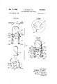
Brief description of the drawings FIGURE 1 is an elevational view of the preferred bulb socket-.filter assembly of this invention in a disassembled condition. `ElIGURE 2 is a plan view of a typical mounting panel to which the bulb socket-filter assembly may be secured and locked. FIGURE 3 is an elevational view showing the preferred bulb socket-filter assembly of this invention in an assembled condition. FIGURE 4 is a plan view of the upper side of the mounting panel with the bulb socket-filter lassembly secured thereto. FIGURE 5 is a cross sectional view of the bulb socket-filter assembly taken along 'line 5--5 of FIGURE 4. FIGURE 6 is a cross sectional view of the bulb socket-filter assembly taken along line 6-6 of FIGURE 5.
Description of the preferred embodiment In the description of the preferred embodiment of the bulb socket-filter assembly of this invention, the socket of the assembly will be `described as being of the type utilized in conjunction with baseless bulbs. However, it should be understood that this is not the only type of bulb which may be utilized with the assembly of this invention as the socket may be adapted to receive other types of bulbs by changing the terminals associated with the socket. The preferred embodiment of the bulb socketlter assembly of this invention is also described in conjunction with its utilization in a mounting panel or dash panel of a motor vehicle. It should also be understood that the use of the bulb socket-filter assembly in this particular application is merely illustrative and that the assembly may be utilized in many other applications other than in the -dash boards of motor vehicles.
In `FIGURE 1 there is shown the bulb socket-filter assembly of this invention, generally identified by the numeral 10. The bulb socket, generally identified by the numeral l1v1, of the assembly -10 is of the general type for receiving baseless bulbs and is injection molded of a plastic material which `is electrically insulating. As best seen in FIGURES 5 and 6, the socket 11 has an insulating body 12 of generally rectangular configuration, the insulating body defining a cavity 13 having two interconnected chambers t'14 and 16, best seen xin FIGURE 5. Each chamber receives an individual metal terminal `17 or 18 therein and each terminal has a portion thereof 17a or 18a for enga-ging and supporting one of the terminals 19 or 21 on the base of a baseless bulb l22 lwhich is inserted within the cavity `13 of the insulating body 12. Each terminal v17 or 18 also has a portion 17b or 18b which extends over ends of the cavity 13 for a purpose which will be described in detail herein below.
Returning now to FIGURES 1 and 3, the bulb socketfilter assembly has a filter element, generally identified by the numeral 23. The [filter element I23 is molded of a suitable electrically insulating material, which material is transparent to light and tinted with a color such as blue, green, yellow or whatever filter color hue is `desired for the light passing through the filter.
As best seen in FIGURES 1 and 4, in the preferred embodiment of the filter element 23, the element is formed so as to have a pair of locking shoulders 24 and 26, the Shoulders being spaced apart by openings 24a or 26a (FIGURE 4) which permit terminal portions 17b and 18b to pass therethrough. The locking shoulders 24 and 26 extend perpendicularly outward of the central axis of the filter element 23. From FIGURE 4 it is also noted that the locking shoulders 24 and 26 are of approximately equal arcuate length.
, As best seen in FIGURES 1 and 3, two cam securing members, generally identified by the numerals 27 and 28, are attached and formed integrally with the preferred form of the filter element 23. Respective ones of the cam securing members 27 and 28 have lug or cam locking portions 27a or 28a associated therewith, which portions extend outwardly from the filter element 23 in a direction generally parallel to the shoulders 24 and 26, a distance slightly less than the diameter of cut-out portions 29 of an aperture 31 in a mounting panel 32. It should also be noted from FIGURE 1 that each lug or cam locking portion 27a or 28a has a tapered surface 27b or 28b for aiding in securing the socket-filter assembly 10 to the mounting panel 32. The tapered surfaces 27b or 28b are spaced longitudinally from the locking shoulders 24 and 26, a `distance approximately equal to the thickness of the mounting panel 32.
With reference to FIGURES 1, 3 and 4, the filter element 23 is secured to the bulb socket 11 by means which are now to be described. The filter 23 has a pair of depending legs 33 and 34 associated therewith. The legs 33 and 34, which extend down from the under surface of the Ilocking shoulders 24 and 26 of the filter element 23, have associated therewith tab portions 33a and 34a, respectively. In their normal position, the distance of separation between the tab portions 33a and 34a of the legs 33 and 34 is a distance slightly greater than the distance between openings 36 and 37 (see FIGURE 4) which are located, respectively, in projecting portions 38 and 39 Iwhich extend perpendicularly outwardly from the bottom of the bulb socket 11.
Formed integrally with and extending from the bottom of the insulating body 12 of the bulb socket 11 is a locking tab member 41. As best seen in FIGURES l and 4, the locking tab 41 extends upwardly from its area of attachment with the insulating body 12 between the locking shoulder 24 and cam securing member 27 and terminates at its free-end 42 a distance above the open end of the cavity -13 approximately equal to the height above the insulating body `12 at which the cam securing members 27 and 28 are spaced when the filter element 23 is assembled with the socket `111 (FIGURE 3). The locking tab member 41 Iis spaced from the insulating body 12 by a space 43 over sustantially a'll of the length thereof so that the lock-ing tab member 41 is `deformable at its free-end `42. The free-end of the locking tab member is deformable or flexible from a normal position, where it is on substantially the same diameter as the end wall 44 (FIGURE 2) of the cut-out portions 29 of the aperture 31 of mounting panel 32, to a deflected position, where it is on a diameter smaller than the diameter of the circular aperture 31 of the mounting panel 32.
Operation The assembly of the filter element 23, the baseless bulb 22 and the bulb socket 11 to form a socket-filter assembly '4 10 will now be described. After that description, the manner of attaching the completed assembly 10 to the mounting panel 32 will be described in detail.
To form the socket-filter assembly 10, the baseless bulb 22 is inserted into the cavity 13 of the insulating body 12 so that the termina-ls 19 and 21 of the bulb engage, respectively, the metal terminals 17a and 18a positioned -in chambers 114 and 16 of the cavity 13. The bulb 22 is now supported within the bulb socket 11.
The filter element 23 is assembled to the bulb socket 11 by gripping the legs 33 and 34 depending from the element and depressing the same towards one another. The filter element 23 is moved so that the tab portions 33a and 34a of the resepctive Ilegs are received Within the respective openings 36 and 37 of the projecting portions 38 and 39 located near the bottom of the insulating body 1v1. The openings 26a and 27a in the shoulders 26 and 27 of the filter element 23 permit respective ones of the terminals 17b and 1811 to extend out from the socket 11 when the lfilter 23 is assembled to the socket. The assembled structure lis shown best in FIGURE 3.
The entire bulb socket-filter assembly 10 is inserted into the aperture 31 of the mounting panel 32 in the following manner. The insulating body 12 of the bulb socket 1:1 is grasped and manual pressure applied to the free-end 42 of the locking tab member 41 to defiect the same to its deflected position wherein it is on a diameter smaller than the diameter of the circular aperture 31 of the mounting panel 32. The socket-filter assembly 10 is inserted into the aperture 31 from the rear or lower surface of the mounting panel 32 by initially aligning the cam securing members 27 and 28 with respective ones of the cut-out portion 29-29 of aperture 31. The bulb socket-filter assembly 10 is inserted into the aperture 31 until upwardly facing surfaces of shoulders 24 and 26 engage the rear or lower surface of the mounting panel 32, at which time the tapered surfaces 27b or 28b of the cam securing members 27 and 28, respectively, are positioned slightly above the front or upper surface of mounting panel 32. When the assembly 10 is initially inserted in the aperture 31, the deiiectable locking tab member 41 has the free-end 42 thereof in engagement with the side wall of the circular aperture 31.
With particular reference to FIGURE 4, the bul socket-filter assembly 10 is secured to the mounting panel 32 by rotating the assembly 10 from its initially inserted position in a counter-clockwise direction as viewed in FIGURE 4. When in the locked position, the locking shoulders 24 and 26 are in engagement with the rearor lower surface of the mounting panel 32 while at the same time the lug or cam lock portions 27a and 28a, respectively, of the cam securing members 27 and 28 are in engagement with the upper surface of the mounting panel 26 whereby the bulb socket-filter assembly is secured to the panel 32. The extending portions 17b and 18b of terminals 17 and 18, respectively, engage printed circuit patterns 47 and 48 (FIGURE 4) on the mounting panel 32. The terminal portions 17b and 18b also provide for some resiliency between the assembly 10 and the mounting panel 32.
Rotation of the assembly 10 after its initial insertion brings the free-end 42 of the locking tab member 41 into alignment with one of the cut-out portions 29 of the aperture 31. When so aligned, fthe free-end 42 of the tab 41 resiliently returns towards its normal position thereby to enter la selected one of the circular `cut-out portions 29 of the .aperture 31. When the `free-end 42 of the locking tab member 41 is in the cut-out portion 29, it provides a lock to insure that the socket assembly y10 is not freely rotatable with respect to the mounting panel 32. Once the bulb socket-filter assembly is locked to the mounting panel 32, vibrations or other shocks applied to the mounting panel 32 will not cause `a kdisengagement of the lassembly 10 from the panel.
'Ilhere has been disclosed Iherein ra preferred embodiment of the socket assembly of this invention. However, there are many modifications thereof which may be made by one skilled in the art and which are within the spirit and scope of this invention. More particularly, for example, the cam locking portions 27 and 28 and the locking shoulders 24 and 26 may be contained on the bulb socket 11 rather than on the filter 23. Also, the bulb socket 11 could support one portion of the cam-shoulder locking means while the other portion thereof is supported by the filter. Also, the Vlocking tab member 41 could be mounted' on the filter `23. Likewise, the tab member 41 could eX- tend from the iilter 23 downwardly to form part of the means for locking the ilter `23 to the insulating body 12. This particular type of lock could be accomplished so long as the locking tab member was `freely ilexible in the area between the locking shoulder and the cam locking portions of the lfilter.
The bulb socket-filter assembly of this invention will have lmany apparent modifications to those skilled in the art. `It is intended that all such modifications which fall within the true spirt and scope of this invention be included within the scope of the appended claims.
What is claimed is:
1. In a bulb socket-filter assembly which includes: a mounting panel having an aperture therein, said aperture having opposed cut-out portions; an insulating body dening a cavity open at one end; terminal means within said cavity of said insulating body for receiving and supporting a bulb therein; a light filter element; means for 'attaching said light iilter element Ito said insulating body in a position overlying said cavity thereby to form a socket-filter assembly; and shoulder and cam means on said socket-filter assembly for securing said assembly to said panel by rotation of said assembly after `insertion of the cam portion of said shoulder and cam means through said pair of opposed cut-out portions of said aperture thereby to cause engagement of said cam portion of said means with the upper surface of said mounting panel and said shoulder portion of said means with the lower surface of said mounting panel; the improvement in said means for attaching said light filter to said insulating body in a position overlying said cavity which comprises:
a pair of projecting portions extending from opposed sides of said insulating body at a position near the closed end thereof, each of said projecting portions having an opening therethrough; and a pair of legs having tab portions on the free ends thereof depending from said light :filter element a distance suiiicient that when said tab ends of sad legs are inserted into the openings of said projecting portions of said insulating body, said light filter element `is in a position overlying said cavity of said insulating body.
2. The bulb socket-filter assembly as defined in claim 1 wherein: said shoulder and cam means `are located on said light tilter element.
3. The bulb socketdilter assembly as defined in claim 2 wherein: said assembly has a deectable locking means integral with an extending from said assembly, said locking means having a free-end defleotable during insertion of said assembly into said 'aperture and received Within one of said cut-out portions of said aperture to lock said assembly against substantial rotative movement with respect to said mounting panel when said panel is subjected to shock or other vibrational forces.
4. A bulb socket-filter assembly which is adaptable to be mounted directly into a circular aperture of a mounting panel having opposed cut-out portions with circular end walls, said `socket-filter assembly comprising: an insulating body defining a cavity open lat one end 'and having two interconnected chambers; two terminals, one of said terminals being received in each of said chambers of said body and each of said terminals both having a portion thereof for engaging and supporting within said chamber one of the lead terminals on the base portion of a baseless bulb insertable within said chamber, and having a portion thereof which extends upwardly and outwardly over the surface at said open end of said insulating body; a pair of projecting portions extending from opposed sides of said `insulating body, each of said projecting portions having an opening therethrough; a locking tab member attached at one end to said insulating body and having a free-end extending upwardly along and outwardly from said insulating body to a height spaced above the open end of said cavity to be received within said cut-out portion of said aperture to lock said assembly against substantial rotative movement with lrespect to said mounting panel; a light tilter element; a pair of shoulders located on a lower portion of said iilter element and' extending outwardly therefrom to a predetermined diameter about the central axis of said 'filter element, said shoulders being spaced apart arcuately and having a notch therein for allowing said terminals to pas-s therethrough outwardly over the surace of the open end of said insulating body when said insulating body and said light filter element are in an assembled condition; two arcuately spaced cam securing members integral with said lter element and spaced above said shoulders of said element a distance equal to the thickness of said -mounting panel, said cam securing members being located on a diameter slightly less than the diameter of said cutout portions of said mounting panel; a pair of Idepending legs having tab portions on the free-end thereof, said legs extending downwardly from the under surface of said shoulders of said ilter element a distance suiiicient that when said tab ends of said legs `are inserted into said openings of said projecting portions of said insulating body to secure said light filter element to said insulating body, the under surface of said locking shoulders are in engagement with the surface of the insulating body at said open end thereof.
References Cited UNITED STATES PATENTS 1,842,025 1/ 1932 Huebner 240--152 2,903,570 9/1959 Worden 240-46.57 3,007,599 1l/l961 Greasley 240--152 3,050,705 8/ 1962 Benson 339-127 3,229,083 1/ 1966 George 240--152 NORTON ANSHER, Primary Examiner RICHARD M. SHEER, Assistant Examiner U.S. Cl. X.R.
Applications Claiming Priority (1)
| Application Number | Priority Date | Filing Date | Title |
|---|---|---|---|
| US62716667A | 1967-03-30 | 1967-03-30 |
Publications (1)
| Publication Number | Publication Date |
|---|---|
| US3473015A true US3473015A (en) | 1969-10-14 |
Family
ID=24513488
Family Applications (1)
| Application Number | Title | Priority Date | Filing Date |
|---|---|---|---|
| US627166A Expired - Lifetime US3473015A (en) | 1967-03-30 | 1967-03-30 | Bulb socket with light filter |
Country Status (3)
| Country | Link |
|---|---|
| US (1) | US3473015A (en) |
| DE (1) | DE1764080A1 (en) |
| GB (1) | GB1226576A (en) |
Cited By (21)
| Publication number | Priority date | Publication date | Assignee | Title |
|---|---|---|---|---|
| US3591793A (en) * | 1968-12-23 | 1971-07-06 | Jack D Mckim | Panel light assembly |
| US3611360A (en) * | 1969-11-19 | 1971-10-05 | Switchcraft | Readily replaceable jewel lamp assembly for jack panels |
| US3699495A (en) * | 1970-02-21 | 1972-10-17 | Amp Inc | Electrical connector for vehicle instruments |
| US3731260A (en) * | 1971-05-06 | 1973-05-01 | Microdot Inc | Socket housing |
| US3742211A (en) * | 1972-09-01 | 1973-06-26 | Honeywell Inc | Lamp removal arrangement |
| US4089048A (en) * | 1975-01-28 | 1978-05-09 | Nartron Corporation | Lens structure |
| US4122367A (en) * | 1976-02-12 | 1978-10-24 | U.S. Philips Corporation | Electric incandescent lamp having a centering ring |
| US4373771A (en) * | 1980-11-10 | 1983-02-15 | General Motors Corporation | Lamp socket |
| US4398240A (en) * | 1978-05-19 | 1983-08-09 | Savage John Jun | Lens cap holder for attachment to circuit boards |
| US4471414A (en) * | 1982-03-11 | 1984-09-11 | Savage John Jun | Integrated light unit and circuit element attachable to circuit board |
| US4477864A (en) * | 1982-07-15 | 1984-10-16 | General Motors Corporation | Lamp assembly |
| US4491900A (en) * | 1982-09-27 | 1985-01-01 | Savage John Jun | Lens and mount for use with electromagnetic wave source |
| US4722028A (en) * | 1986-06-10 | 1988-01-26 | Staco Switch | Night vision compatible and sunlight readable, lighted, word indicating pushbutton switch and indicator |
| US4899263A (en) * | 1984-11-02 | 1990-02-06 | Casco Products Corporation | Lamp fixture for illuminating interior of cigar lighter socket |
| US5130904A (en) * | 1990-04-20 | 1992-07-14 | Koito Manufacturing Co., Ltd. | Automotive headlamp waving no ultraviolet output |
| US5918966A (en) * | 1995-03-03 | 1999-07-06 | W. Albrecht Gmbh & Co. Kg | Light with colored silicone cap |
| US6283618B1 (en) | 1999-06-07 | 2001-09-04 | Lsi Industries Inc. | Luminaire assembly |
| US6502962B1 (en) | 2000-10-23 | 2003-01-07 | Fire Products Company | Cover assembly for a light |
| US20070064449A1 (en) * | 2004-02-04 | 2007-03-22 | Erik Bornemeier | Light holder system |
| US20090268471A1 (en) * | 2008-04-24 | 2009-10-29 | Chin-Chung Chen | Lens device and illumination apparatus having the same |
| US20100055976A1 (en) * | 2008-09-03 | 2010-03-04 | Hosiden Corporation | Connection structure of circuit board and connecting device |
Citations (5)
| Publication number | Priority date | Publication date | Assignee | Title |
|---|---|---|---|---|
| US1842025A (en) * | 1930-08-11 | 1932-01-19 | Edgar J Huebner | Electrical fixture |
| US2903570A (en) * | 1954-08-27 | 1959-09-08 | C M Hall Lamp Co | Lamp assembly |
| US3007599A (en) * | 1957-04-24 | 1961-11-07 | United Carr Fastener Corp | Member for assembly in an aperture in a support |
| US3050705A (en) * | 1959-07-14 | 1962-08-21 | United Carr Fastener Corp | Electrical assembly |
| US3229083A (en) * | 1963-05-22 | 1966-01-11 | Jr Ben B George | Replaceable miniature lamp assembly |
-
1967
- 1967-03-30 US US627166A patent/US3473015A/en not_active Expired - Lifetime
-
1968
- 1968-03-28 GB GB1226576D patent/GB1226576A/en not_active Expired
- 1968-03-29 DE DE19681764080 patent/DE1764080A1/en active Pending
Patent Citations (5)
| Publication number | Priority date | Publication date | Assignee | Title |
|---|---|---|---|---|
| US1842025A (en) * | 1930-08-11 | 1932-01-19 | Edgar J Huebner | Electrical fixture |
| US2903570A (en) * | 1954-08-27 | 1959-09-08 | C M Hall Lamp Co | Lamp assembly |
| US3007599A (en) * | 1957-04-24 | 1961-11-07 | United Carr Fastener Corp | Member for assembly in an aperture in a support |
| US3050705A (en) * | 1959-07-14 | 1962-08-21 | United Carr Fastener Corp | Electrical assembly |
| US3229083A (en) * | 1963-05-22 | 1966-01-11 | Jr Ben B George | Replaceable miniature lamp assembly |
Cited By (23)
| Publication number | Priority date | Publication date | Assignee | Title |
|---|---|---|---|---|
| US3591793A (en) * | 1968-12-23 | 1971-07-06 | Jack D Mckim | Panel light assembly |
| US3611360A (en) * | 1969-11-19 | 1971-10-05 | Switchcraft | Readily replaceable jewel lamp assembly for jack panels |
| US3699495A (en) * | 1970-02-21 | 1972-10-17 | Amp Inc | Electrical connector for vehicle instruments |
| US3731260A (en) * | 1971-05-06 | 1973-05-01 | Microdot Inc | Socket housing |
| US3742211A (en) * | 1972-09-01 | 1973-06-26 | Honeywell Inc | Lamp removal arrangement |
| US4089048A (en) * | 1975-01-28 | 1978-05-09 | Nartron Corporation | Lens structure |
| US4122367A (en) * | 1976-02-12 | 1978-10-24 | U.S. Philips Corporation | Electric incandescent lamp having a centering ring |
| US4398240A (en) * | 1978-05-19 | 1983-08-09 | Savage John Jun | Lens cap holder for attachment to circuit boards |
| US4373771A (en) * | 1980-11-10 | 1983-02-15 | General Motors Corporation | Lamp socket |
| US4471414A (en) * | 1982-03-11 | 1984-09-11 | Savage John Jun | Integrated light unit and circuit element attachable to circuit board |
| US4477864A (en) * | 1982-07-15 | 1984-10-16 | General Motors Corporation | Lamp assembly |
| US4491900A (en) * | 1982-09-27 | 1985-01-01 | Savage John Jun | Lens and mount for use with electromagnetic wave source |
| US4899263A (en) * | 1984-11-02 | 1990-02-06 | Casco Products Corporation | Lamp fixture for illuminating interior of cigar lighter socket |
| US4722028A (en) * | 1986-06-10 | 1988-01-26 | Staco Switch | Night vision compatible and sunlight readable, lighted, word indicating pushbutton switch and indicator |
| US5130904A (en) * | 1990-04-20 | 1992-07-14 | Koito Manufacturing Co., Ltd. | Automotive headlamp waving no ultraviolet output |
| US5918966A (en) * | 1995-03-03 | 1999-07-06 | W. Albrecht Gmbh & Co. Kg | Light with colored silicone cap |
| US6283618B1 (en) | 1999-06-07 | 2001-09-04 | Lsi Industries Inc. | Luminaire assembly |
| US6561676B1 (en) | 1999-06-07 | 2003-05-13 | Lsi Industries Inc. | Luminaire assembly |
| US6733158B2 (en) | 1999-06-07 | 2004-05-11 | Lsi Industries Inc. | Wiring box for a luminaire assembly |
| US6502962B1 (en) | 2000-10-23 | 2003-01-07 | Fire Products Company | Cover assembly for a light |
| US20070064449A1 (en) * | 2004-02-04 | 2007-03-22 | Erik Bornemeier | Light holder system |
| US20090268471A1 (en) * | 2008-04-24 | 2009-10-29 | Chin-Chung Chen | Lens device and illumination apparatus having the same |
| US20100055976A1 (en) * | 2008-09-03 | 2010-03-04 | Hosiden Corporation | Connection structure of circuit board and connecting device |
Also Published As
| Publication number | Publication date |
|---|---|
| DE1764080A1 (en) | 1971-04-29 |
| GB1226576A (en) | 1971-03-31 |
Similar Documents
| Publication | Publication Date | Title |
|---|---|---|
| US3473015A (en) | Bulb socket with light filter | |
| US6357902B1 (en) | After market LED taillight bulb | |
| US4831503A (en) | Modular rear deck lighting cluster | |
| US6493232B2 (en) | Housing for an electronic control device in vehicles | |
| US20050013095A1 (en) | Electrical junction box | |
| DE112009004314T5 (en) | Lighting device for a headlight source | |
| KR19980032405A (en) | Switch connection structure | |
| US3210532A (en) | Illumination and mounting means | |
| KR100289215B1 (en) | Switch connection structure | |
| KR100289217B1 (en) | switch | |
| DE3105691A1 (en) | LIGHT UNIT | |
| US4564883A (en) | Control unit for a motor vehicle which can be accommodated in a trim component | |
| US3208031A (en) | Lamp socket with shock-free mounting | |
| US3115307A (en) | Automotive vehicle marker lamp | |
| US6384538B1 (en) | Control apparatus for a light unit for vehicles | |
| US3577116A (en) | Lamp socket and terminal | |
| US3887258A (en) | Wire connector means for vehicle lamp | |
| US4070566A (en) | Marker lamp assembly | |
| DE19941525B4 (en) | headlights | |
| US2863989A (en) | Microscope illuminator | |
| US4793815A (en) | Electrical connector | |
| FR2444589A1 (en) | Internal lighting of motor vehicle - comprises support for lamp assembly and has electrical connector with diffusing cover (SW 21.7.80) | |
| US3425034A (en) | Vehicle signal lamp system | |
| SE460005B (en) | DEVICE FOR CONNECTING A POWER OUTLET OR A WALL POWER SUPPLIER TO A CONTROL DEVICE | |
| ATE132090T1 (en) | VEHICLE LIGHT |