US3542965A - Inter-office call diverter - Google Patents
Inter-office call diverter Download PDFInfo
- Publication number
- US3542965A US3542965A US737979A US3542965DA US3542965A US 3542965 A US3542965 A US 3542965A US 737979 A US737979 A US 737979A US 3542965D A US3542965D A US 3542965DA US 3542965 A US3542965 A US 3542965A
- Authority
- US
- United States
- Prior art keywords
- station
- transfer
- circuit
- call
- marker
- Prior art date
- Legal status (The legal status is an assumption and is not a legal conclusion. Google has not performed a legal analysis and makes no representation as to the accuracy of the status listed.)
- Expired - Lifetime
Links
Images


Classifications
-
- H—ELECTRICITY
- H04—ELECTRIC COMMUNICATION TECHNIQUE
- H04Q—SELECTING
- H04Q3/00—Selecting arrangements
- H04Q3/42—Circuit arrangements for indirect selecting controlled by common circuits, e.g. register controller, marker
- H04Q3/54—Circuit arrangements for indirect selecting controlled by common circuits, e.g. register controller, marker in which the logic circuitry controlling the exchange is centralised
- H04Q3/545—Circuit arrangements for indirect selecting controlled by common circuits, e.g. register controller, marker in which the logic circuitry controlling the exchange is centralised using a stored programme
-
- Y—GENERAL TAGGING OF NEW TECHNOLOGICAL DEVELOPMENTS; GENERAL TAGGING OF CROSS-SECTIONAL TECHNOLOGIES SPANNING OVER SEVERAL SECTIONS OF THE IPC; TECHNICAL SUBJECTS COVERED BY FORMER USPC CROSS-REFERENCE ART COLLECTIONS [XRACs] AND DIGESTS
- Y10—TECHNICAL SUBJECTS COVERED BY FORMER USPC
- Y10S—TECHNICAL SUBJECTS COVERED BY FORMER USPC CROSS-REFERENCE ART COLLECTIONS [XRACs] AND DIGESTS
- Y10S379/00—Telephonic communications
- Y10S379/914—Programmable telephone component
Definitions
- the Voice communication path from the calling station is always extended to the transfer station through auxiliary equipment associated with the called line.
- auxiliary equipment associated with the called line.
- I. Wicks U.S. Pat. 2,274,759 dated Mar. 3, 1942 teaches a transfer system wherein the auxiliary circuits for bridging the incoming call to the transfer station are permanently associated with the called subscribers telephone.
- An improvement over this arrangement is disclosed in the W. Whitney U.S. Pat. 3,377,433 dated Apr. 9, 1968 which teaches a transfer system wherein the auxiliary voice bridging circuits are associated with the called line only while a call is being processed involving the called line.
- a register which is attached to the established connection at the calling oice in response to the signal, causes the C appearance of the switching circuit in the called office to initiate a connection to a sender.
- the sender in the called oiiice thereupon transmits to the register in the calling oce, the directory digits of the transfer station.
- the original connection between the calling ofce and the called office then releases and a new connection is established to the transfer station under control of the calling ofce in the same manner as though the call had originated in the calling office. Communication is thereby possible from the calling station to the transfer station through the normal switching system without the insertion of auxiliary transfer circuits or switching offices into the nal voice connection. Thus, proper transmission quality is maintained on the transfer connection at all times.
- a temporary call transfer switching system is arranged to accomplish the actual transfer at a switching ofce serving a calling station.
- a called office of a multiple oiiice switching system is arranged to recognize the special status of a called line and to initiate a connection from a calling oice to a preselected transfer station independent from an originally established connection from the calling oice to the called oice.
- a switching system at the called oce is arranged to recognize the special status of a called line and to divert calls incoming to that line to an auxiliary transfer circuit and to thereupon transmit to the calling office the digits of a transfer number to which calls are to be transferred.
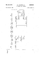
- FIGS. 2 through 14 are schematic drawings showing in greater detail the interrelation of the components of the exemplary embodiment.
- FIGS. 2 through 14 employ a type of notation referred to as detached contact in which an X shown intersecting a conductor represents a normally open contact of a relay and a bar shown intersecting a conductor at right angles represents a normally closed contact of a relay; normally referring to the unoperated condition of the relay.
- the principles of this type of notation are described in an article entitled An Improved Detached Contact Type Schematic Circuit Drawing by F. T. Meyer in the September 1955 publication of the American Institute of the Electrical Engineers Transactions, Communications and Electronics, vol. 74, pages 505-513.
- the relays, relay contacts and other electromechanical devices shown in FIGS. 2 through 14 have been given systematic designations.
- the number preceding the letters of each device correspond to the iigure in which the control circuit of the de vice is shown.
- the coil of relay 5T is shown in FIG. 5.
- Each relay contact, either make, break or transfer, is shown with its specific contact number preceded by the designation of the relay to which it belongs.
- the notation 5T-1 indicates contact number 1 of relay 5T, the coil of which is shown in FIG. 5.
- memory circuit 7 may constitute any one of a number of configurations well known in the art operable to electrically record information in binary form at preselected address locations, each of which address location is effective to provide the information stored therein on a nondestructive read-out basis.
- marker circuit ⁇ 8 is arranged, as described in the aforementioned Busch patent, to connect line link frame 2 appearance R with trunk link frame 3 appearance X in the normal manner such that digits transmitted from station S2 will be received in originating register circuit 6.
- marker circuit 8 then causes the registration of the class of service and the calling line equipment location of station S2 in the originating register. The marker thereupon releases from the connection.
- incoming trunk circuit ⁇ 4 is activated by an incoming call which is directed to station S2.
- number group circuit 11 is interrogated to determine the line equipment information and ringing combination of the called party.
- the marker is arranged to recognize the privileged status of the called station fro-m its preassigned ringing combination.
- the preassignment of a specified ringing combination may be utilized, as herein set forth.
- numerous other techniques may be employed. For example, an additional translation indication may be returned by the number group in the manner set forth in T. V. Burns et al., U.S. Pat. 3,264,415, dated Aug. 2, 1966.
- ringing tone is applied to the line.
- the switching circuit is arranged to immediately detect this ringing potential and to trip the ringing.
- the switching circuit thereupon initiates a signal over the extended linkage path to the calling oice A.
- This signal is detected in the calling oflice by the outgoing trunk 101 which is arranged, via an auxiliary line link frame appearance Z to initiate a dial tone connection and thus have an originating register attached in the normal manner. Attachment of the originating register causes the auxiliary switching circuit in the called ofiice, in the manner to -be more fully detailed hereinafter, to become attached through the switching network to a sender for the transmission of the digital directory number of the transfer station S3.
- the called office may be aranged to select, from a class of service code assigned to the incoming trunk, whether the calling office is equipped for automatic call transfer.
- the incoming connection may have been switched through numerous switching offices it would be necessary to modify each of these offices in order to insure that the proper trunk is selected for the final connection to the called oce.
- station S2 is arranged for temporary call transfer service.
- the corresponding class of service designation is class of service 29. It will thus be obvious, as set forth in the Busch patent, that during the establishment of an originating or terminating connection involving station S2, marker circuit 8 will ascertain the class of service of station S2 to be that designated 29 and therefore will function in accordance with that class of service in processing such connections.
- station S2 desires to have incoming calls transferred to some other telephone location such as station S3 as hereinbefore set forth.
- relays 7CAO, 7CA1, 7CBO and 7CB1 (FIG. 7) operate over an obvious path from the corresponding leads of the register relays, FIG. 3, via cable 57.
- These relays thereupon lock operate in an obvious manner and provide an operate path for the TIT relay from battery through the winding of the relay, released break contact 7CB2-1, enabled make contacts 7CB1-1, 7CBO-3, 7CA1-1 and 7CAO-1, to ground which, as has been set forth previously, is present on output lead A of class of service translator circuit 707.
Description
Nov. 24, 1970 E. J. wlLKENs, JR
14 Sheets-Sheet 2 aus; $1 aus: 22 b 22: 2-205 5W, :$53 @la n-1-, f3? BUS: SEE SGE 5 aus: Sy m 1-| |||x| E. J. WILKENS, JR
INTEROFFICE CALL DIVERTER Nov. 24, 1970 Filed June 18, 1968 Nov. 24, 1970 E J. wlLKENs, JR
INTEROFFICE CALL' DIVERTER y 14 Sheets-Sheet 3 Filed June 18, 1968 Nov. 24, 1970 E. J. wILKENs, JR
INTEROFFICE CALL DIVERTER Filed June les,k 196e 14 Sheets-Sheet 6 @In @JUNG SUN:
Nov. 24, 1970 E. J. wlLKENs, JR
INTEROFFICE CALL DIVERTER 14 Sheets-Sheet 7 Filed June 18, 1968 nmNlZOv .vINm und Nmu W P mmv QNIZOV omo Nov. 24, 1970 E, J, wlLxENs, JR y3,542,965
INTEROFFICE CALL DIVERTER l 14 Sheets-Sheet 8 dll...
Filed June 18, 1968 @tu AEV e@ mom Nov. 24, 1970 E. J. WILKENS, JR
INTEROFFICE CALL DIVERTER Filed June 18, 1968 14 Sheets-Sheet 9 Nov. v24, 1970 E. J. wlLKENs. .I R
INTEROFFICE CALL DIVERTER Filed June 18, 1968 14 Sheets-Sheet 11 @s E-IE ill.
Il TI m UU ww A Nov. 24, 1970 E. J. wlLKENs, JR 3,542,965
INTEROFFICE CALL DIVERTER Filed June 18, 1968 14 Sheets-Sheet 12,
Nov. 24, 1970k E. J. wlLKENs, JR
BACKGROUND OF THE INVENTION Field of the invention This invention relates generally to telephone switching systems and more particularly to switching network arrangements within such systems wherein calls directed to a particular subscriber are completed instead to some other telephone station arbitrarily preselected by the called subscriber for a selected interval of time.
Description of the prior art Extensive development of telephone switching systems in recent years has made possible the provision of numerous special features which render telephone service more convenient and more flexible. For example, circuit arrangements have been provided whereby a special service subscriber, who is to 'be absent from his telephone for some period of time, may have incoming calls diverted to some other telephone station during such absence.
In existing temporary call transfer arrangements the Voice communication path from the calling station is always extended to the transfer station through auxiliary equipment associated with the called line. For example, the I. Wicks U.S. Pat. 2,274,759 dated Mar. 3, 1942 teaches a transfer system wherein the auxiliary circuits for bridging the incoming call to the transfer station are permanently associated with the called subscribers telephone. An improvement over this arrangement is disclosed in the W. Whitney U.S. Pat. 3,377,433 dated Apr. 9, 1968 which teaches a transfer system wherein the auxiliary voice bridging circuits are associated with the called line only while a call is being processed involving the called line.
An example of a most recent improvement in the utilization of voice bridging auxiliary circuits on transferred connections is disclosed in copending application T. R. Stevens, Ser. No. 737,923, led lune 18, 1968. As set forth therein, the connection between the auxiliary circuit and the called line is obviated by inhibiting the normal completion f an incoming call on that line and directing the call instead to an idle auxiliary switching circuit. The switching circuit thereupon initiates an outgoing call to the transfer station and acts as a bridge between the incoming line and the outgoing line so as to provide ICC a continuous communication path between the calling subscriber and the subscriber at the transfer station.
On long distance connections, however, maintaining proper transmission quality on calls bridged through the called office is difficult. The problem arises because of transmission losses which are encountered on connections extending through more than one switching oiiice. Since the transmission quality is dependent upon the transmission loss of the communication circuit, such loss must be maintained within certain limits for acceptable communication. Accordingly, because each switching otlice through which the call is routed inserts transmission loss, a limitation must be placed on the number of oices which may be interposed between the calling and called station. It follows therefrom that an incoming call which has been switched through a predetermined number of offices cannot be transferred through an additional office since the resultant transmission level may 'be below acceptable standards. Consequently, in the existing temporary call transfer systems, in order to avoid transmission difficulties, restrictions have been placed on the location of the transfer station in relation to the called station. Some installations have gone so far as to require that the transfer station be located within the same switching office as the called station. Thus, in present systems, the flexibility of the temporary transfer feature is severely limited.
In view of the foregoing, an object of this invention is to provide a temporary call transfer switching system which may be simply and economically implemented in existing systems so as to obviate the necessity for an extended connection between a calling subscribers oice and a called subscribers office whenever the transfer function is activated.
Another object is to provide a switching system whereby a subscriber may have incoming calls automatically forwarded to any arbitrarily selected telephone station for a selected interval of time while maintaining proper transmission quality in the transfer connection.
A still further o'bject is to provide a temporary call transfer switching system whereby an announcement is transmitted to a calling station indicating the directory number of the transfer station to which calls are currently being directed, whenever the call is unable to be automatically transferred.
SUMMARY OF THE INVENTION These and other objects are obtained in accordance with an exemplary embodiment of the invention wherein a number of subscriber stations are provided with a special service feature known as temporary call transfer. A plurality of auxiliary call transfer circuits are also provided but in significantly lesser quantity than the aforesaid subscriber stations. Each such auxiliary circuit has three appearances: an A appearance, a B appearance, and a C appearance on the line side of the switching oiiice network. A central memory associated with the switching system is arranged with a plurality of address locations each exclusively associated with a station served by the system and each addressable 'by the line equipment location of the respective station.
The switching system of the embodiment eliminates the transmission problem encountered on long distance connections by establishing the actual transfer at the switching office associated with the calling station. A call is forwarded from a calling oiice to a called oice in the normal manner. The called oice is arranged to screen incoming calls to determine whether the call is to be completed to the called station or is to be transferred. Upon determination that a particular call is to be transferred, the incoming trunk, which is normally connected to the called subscribers line, is connected instead to the line link frame A appearance of an idle auxiliary transfer circuit. The transfer circuit thereupon signals the calling oice over the established communication path that the call is to be transferred. A register, which is attached to the established connection at the calling oice in response to the signal, causes the C appearance of the switching circuit in the called office to initiate a connection to a sender. The sender in the called oiiice thereupon transmits to the register in the calling oce, the directory digits of the transfer station. The original connection between the calling ofce and the called office then releases and a new connection is established to the transfer station under control of the calling ofce in the same manner as though the call had originated in the calling office. Communication is thereby possible from the calling station to the transfer station through the normal switching system without the insertion of auxiliary transfer circuits or switching offices into the nal voice connection. Thus, proper transmission quality is maintained on the transfer connection at all times.
In the event the calling office is not arranged for automatic call transfer, as above set forth, the calling oice does not acknowledge the interrogation signal transmitted from the switching circuits. Under this condition, the B appearance of the switching circuit at the called otlice is connected to an announcement circuit and an audible announcement is provided to the calling station over the established connection indicating the directory number of the transfer station to which the call should be directed. The calling subscriber may then redial the connection in accordance with the information received.
In accordance with one feature of my invention, a temporary call transfer switching system is arranged to accomplish the actual transfer at a switching ofce serving a calling station.
In accordance with another feature of my invention, a switching system is arranged to recognize a special status of a called line and to thereupon interrogate the calling oflice over the established communication path to determine whether the directory number of a transfer station should be lreturned in digital form or whether an audible announcement containing this information is necessary.
In accordance with another feature of my invention, a called office of a multiple oiiice switching system is arranged to recognize the special status of a called line and to initiate a connection from a calling oice to a preselected transfer station independent from an originally established connection from the calling oice to the called oice.
In accordance with another feature of my invention, a switching system at the called oce is arranged to recognize the special status of a called line and to divert calls incoming to that line to an auxiliary transfer circuit and to thereupon transmit to the calling office the digits of a transfer number to which calls are to be transferred.
In accordance with still another feature of my invention, a switching system is arranged to recognize the special status of a called line so as to divert incoming calls to a transfer circuit and to thereupon connect an audible announcement circuit to the transfer circuit indicating the directory number of Va transfer station to which calls should be directed.
DESCRIPTION OF THE DRAWING The foregoing objects, features and advantages, as well as others of the invention, will be more apparent from the following description of the drawing in which:
FIG. 1 is a block diagram showing the interrelation of the exemplary embodiment of the invention;
FIGS. 2 through 14 are schematic drawings showing in greater detail the interrelation of the components of the exemplary embodiment; and
FIG. shows the manner in which the other gures should be arranged.
It will be noted that FIGS. 2 through 14 employ a type of notation referred to as detached contact in which an X shown intersecting a conductor represents a normally open contact of a relay and a bar shown intersecting a conductor at right angles represents a normally closed contact of a relay; normally referring to the unoperated condition of the relay. The principles of this type of notation are described in an article entitled An Improved Detached Contact Type Schematic Circuit Drawing by F. T. Meyer in the September 1955 publication of the American Institute of the Electrical Engineers Transactions, Communications and Electronics, vol. 74, pages 505-513.
It will also be noted that in order to simplify the disclosure and thus facilitate a more complete understanding of the embodiment, the relays, relay contacts and other electromechanical devices shown in FIGS. 2 through 14 have been given systematic designations. Thus, the number preceding the letters of each device correspond to the iigure in which the control circuit of the de vice is shown. Thus, the coil of relay 5T is shown in FIG. 5. Each relay contact, either make, break or transfer, is shown with its specific contact number preceded by the designation of the relay to which it belongs. For example, the notation 5T-1 indicates contact number 1 of relay 5T, the coil of which is shown in FIG. 5.
INTRODUCTION The present invention is illustrated in an automatic switching system wherein common control circuits are employed to control the establishment of calls through a switching network. `One such system is disclosed in the A. I. Busch, U.S. Pat. 2,585,904, issued Feb. 19, 1952. It is lto be understood that the present invention is not, however, limited to use in a telephone system of this type but may be utilized in other types of switching systems.
The invention is described herein as being embodied in a telephone system of the type disclosed in the cited Busch patent. The invention is particularly concerned with apparatus in marker circuit 8, originating registers 6 and 103, sender S, call transfer switching circuit 12 and in outgoing trunk 101, which are represented by the blocks shown with heavy lines in FIG. 1. The other equipment units of the Busch system are neither shown nor described in detail herein except where necessary for a complete understanding of the invention. The cited Busch patent may be consulted for a complete understanding of the construction and operation of other components of the Busch disclosure.
For purposes of illustration, it is intended that the apparatus of line link frame (LLF)2, trunk link frame (TLF)3, incoming trunks `4 and 110, outgoing trunks 101 and 102, originating registers 6 and 103, number group 11, markers 8, 10S and 111 and senders `5 and 104 be similar to the corresponding apparatus disclosed in the Busch patent. It is also intended that the apparatus of automatic message accounting (AMA) equipment 10 be substantially identical to that disclosed in H. D. Cahill et al., U.S. Pat. 2,599,358, dated Iune 3, 1952. It is further intended that memory circuit 7 may constitute any one of a number of configurations well known in the art operable to electrically record information in binary form at preselected address locations, each of which address location is effective to provide the information stored therein on a nondestructive read-out basis.
In order to simplify the disclosure and thus facilitate an understanding of the invention, the call transfer arrangement at the called oce is arranged in a manner similar to that disclosed in the above-cited Stevens application. It will, of course, be obvious that the present invention is not limited to use with such a switching arrangement but, in fact, may be utilized with any number of temporary call transfer systems.
In order to further facilitate an understanding of the invention, the description of the operation of the exemplary embodiment has been sub-divided into a general description portion designated 1.00 and a detailed description portion designated 2.00. Section 1.00 and its subsections describe the invention in general terms with respect to PIG. 1. Section 2.00 and its subsections describe the invention in detail with respect to FIGS. 2 through 11.
1.00 general descriptiontThe interrelation and function of the equipment units of the exemplary embodiment will now be described with reference to FIG. 1 wherein the interconnection between circuit blocks has been designated by arrows to indicate the direction of circuit action.
For purposes of illustration, we shall assume that a subscriber at station S2 anticipates a need to utilize the temporary call transfer feature which is available to that station. We shall also assume that the station to which the call is to be transferred is located at a point not served by the same switching office. However, as will be more apparent from that which is contained hereinafter, the transfer station may be advantageously located at any switching ofce, including the switching office serving station S2.
1.1 establishment of a transfer number in memory.- Referring now to FIG. 1, when station S2 goes off-hook, marker circuit `8 is arranged, as described in the aforementioned Busch patent, to connect line link frame 2 appearance R with trunk link frame 3 appearance X in the normal manner such that digits transmitted from station S2 will be received in originating register circuit 6. As further set forth in the Busch patent, marker circuit 8 then causes the registration of the class of service and the calling line equipment location of station S2 in the originating register. The marker thereupon releases from the connection.
Dial tone is returned to subscriber station S2 from originating register t5` in the well known manner upon completion of the aforesaid linkage. At this point we shall assume that the subscriber at station S2 has knowledge of a special code `which signifies to the originating register, in a manner to be more fully set forth hereinafter, that the digits which will follow are to be stored in memory for future use as a transfer number. For purposes of illustration, we shall further assume that the code which initiates the temporary call transfer feature is 11. It should be noted at this point that the originating register may be arranged to accept any other combination of digits as an identification code. Accordingly, upon receipt of dial tone from originating register 6i, a subscriber at station S2 dials (or key pulses) the digits l and l into the register. As will be more apparent from that which is contained hereinafter, originating register 6 is arranged to return second dial tone to station S2 a predetermined interval of time after the registration of this two digit code. Accordingly, upon receipt of the second dial tone the subscriber at station S2 transmits the digits corresponding to the directory number of the transfer station. For illustration purposes we shall assume this number to be the directory number of station S3. Upon receipt of these digits the originating register seizes memory circuit 7 in the manner to be more fully described hereinafter.
At this point, it should be noted that the originating register contains the line equipment location of station S2 together with the directory number of the transfer party. Accordingly, the originating register utilizes the equipment location number of station S2. as an address to provide access to a specific physical location within memory circuit `7. At this particular physical location the transfer stations identification number is stored under control of the originating register 6. Upon completion of the memory storage function, the register releases memory circuit 7. As will be more apparent from that which is contained hereinafter, originating register 6 also releases at this time. We shall assume for purposes of simplicity that the subscriber at station S2 now returns the subset to an onhook condition.
Upon the release of originating register 6 the subscriber at station S2 is free to place outgoing calls in the normal manner. However, as will be apparent from that which follows, incoming calls to station S2 will be transferred to the transfer station S3.
1.2 incomingl call diverted to an auxiliary line switching circuit-We shall assume at this point that incoming trunk circuit `4 is activated by an incoming call which is directed to station S2. As set forth in detail in the Busch patent, when the mar-ker receives the called line information, number group circuit 11 is interrogated to determine the line equipment information and ringing combination of the called party. In the instant case, upon so doing, the marker is arranged to recognize the privileged status of the called station fro-m its preassigned ringing combination. To impart this information to the marker, the preassignment of a specified ringing combination may be utilized, as herein set forth. However, it will be obvious from that which is contained hereinafter that numerous other techniques may be employed. For example, an additional translation indication may be returned by the number group in the manner set forth in T. V. Burns et al., U.S. Pat. 3,264,415, dated Aug. 2, 1966.
Proceeding now with the description, in View of the special service status of station S2, the marker 8 is arranged, as will be detailed hereinafter, to interrogate memory 7 to ascertain whether station S2 currently has a transfer number stored therein. For this purpose, the marker utilizes the called line equipment location, as returned by the number group, as an address for the memory. Since the line equipment location associated with station S2 has a transfer number stored in memory, the marker is arranged to hunt, in the well known manner, for an idle call transfer switching circuit, such as switching circuit 12. `Upon ascertaining the idle status of such a circuit, the marker thereupon, in a manner to be detailed hereinafter, causes the equipment location of the A line appearance of the selected switching circuit to be written into memory 7 at the address location of the called line. Memory 7 thereupon causes marker 8 to release the line equipment location information of the called line stored therein and substitutes therefor the line equipment location of the A appearance of the selected switching circuit. Marker 8 then completes the call, in the well known manner, from incoming trunk 4, appearance W on the trunk link frame 3, through the switching network to appearance A of the selected switching circuit. On completion of this connection ringing takes place in the well known manner.
Digressing momentarily, the failure of memory 7 to indicate that a transfer number is presently stored therein corresponding to the equipment location of the called line would result in the marker completing the call in the normal manner to the called station S2.
Returning now to FIG. 1, it is apparent that the incoming call has been diverted from the line appearance of station S2 and completed instead to the A line appearance of an auxiliary circuit. It should be noted that since the marker did not check the line appearance of station S2 for a busy condition prior to completing the call to the auxiliary circuit, the transfer function will proceed irrespective of whether the called station is busy or not.
1.3 interrogation of the calling office by the called office-As previously set forth, upon establishment of a linkage from the incoming trunk to the auxiliary switching circuit, ringing tone is applied to the line. The switching circuit is arranged to immediately detect this ringing potential and to trip the ringing. The switching circuit thereupon initiates a signal over the extended linkage path to the calling oice A. This signal is detected in the calling oflice by the outgoing trunk 101 which is arranged, via an auxiliary line link frame appearance Z to initiate a dial tone connection and thus have an originating register attached in the normal manner. Attachment of the originating register causes the auxiliary switching circuit in the called ofiice, in the manner to -be more fully detailed hereinafter, to become attached through the switching network to a sender for the transmission of the digital directory number of the transfer station S3.
Digressing momentarily, it should Vbe noted that the called office may be aranged to select, from a class of service code assigned to the incoming trunk, whether the calling office is equipped for automatic call transfer. However, since the incoming connection may have been switched through numerous switching offices it would be necessary to modify each of these offices in order to insure that the proper trunk is selected for the final connection to the called oce.
1.4 transmission of the directory number to the calling oce.-As discussed previously, the connection of an originating register at the calling office to the linkage connection between the calling subscriber and the called office causes the attachment of a sender to the connection in the called ofiice. Prior to attaching the sender the marker in the called office, which was called in to complete the linkage from the switching circuit to the sender, recognizes from the class of service associated with the switching circuit that memory 7 must be interrogated in order to process the call further. Accordingly, in the manner to be detailed hereinafter, memory 7 is arranged to correlate the equipment location number of the switching circuit with the equipment location number of the associated called line.
Digressing momentarily, it will be remembered that an association was made in the memory between the A appearance of the switching circuit and the called line when the incoming trunk was connected to the switching circuit. Since the other appearances of the switching circuit are fixed, the memory is able in the well known manner to perform the necessary correlation between a calling appearance and the A appearance associated with the called line.
Returning again to FlG. l, when the called line identity is obtained, the memory transfers to the marker the directory number of the transfer station associated therewith. Upon receipt of this number the marker proceeds to establish a linkage between the switching circuit and the sender as set forth above and transfers to the sender the digits of the transfer station directory number. The sender thereupon transmits, in the well known manner, the directory number over the linkage connection from the called oflice to the originating register at the calling oice.
Summarizing at this point, upon receipt of a call directed to a line arranged for temporary call transfer, the calling office is interrogated to determine whether a transfer stations directory number may be transmitted in digital form or whether a verbal announcement is required. Upon determining that digital transmission is possible, a sender is attached in the called ofce which transmits to an originating register in the calling oflice the information required to complete the call to the transfer station under control of the calling office.
1.5 establishment of a call from the calling ofce to the transfer station-When the originating register in the calling office has received the directory number from the called oice, as previously set forth, the talking path between these oflices is released. The called office is thereby eliminated from the connection at this time. Concurrent therewith, a completing marker, such as marker 105, in the calling office is signaled in the well known manner by the originating register 103 and the call is processed in the normal manner under control of the marker 105.
For purposes of illustration, we shall assume that the transfer station S3 is located at some distant office, such as office C which is served via outgoing trunk 102 from the calling office. Of course, it will be obvious from that which is contained hereinafter that station S3 may be located in any switching ofce including the calling ofice A or the called office B.
In order to complete the call to the transfer station the completing marker seizes outgoing trunk 102 and in the well known manner attaches outgoing sender 104 thereto. The directory number of the transfer station is then transferred to sender 104 and the call is completed via trunk 102 in the calling oce to incoming trunk 110 in the transfer oliice in the normal manner. A talking path is thereby established from calling station S1 through the switching network in the calling oce, through outgoing trunk 101, through its trunk link frame appearance Z, again through the switching network to outgoing trunk 102 and via any intermediate switching ofiices to the incoming trunk at the transfer office C and to the transfer station S3 in the normal manner.
1.6 transmission of an audible announcement lo the cal/ing station-In the situation Where the calling office is not equipped to automatically receive the transfer stations directory number, such as when the calling office is a manual office, an originating register is not attached to the established connection in response to the interrogation signal transmitted from the called ofce. The switching circuit at the called office is arranged, as more fully detailed hereinafter, to detect the absence of the originating register at the calling oice and accordingly initiate a connection through the switching network to an available announcement circuit, such as announcement circuit 16. Marker 8 is arranged to transfer to announcement circuit 16 the directory number of the transfer station which is obtained from memory 7 in the manner previously set forth. Announcement circuit 16 thereupon audibly transmits, via the switching network at the called office B and the switching circuit 12, over the interoffice trunk and any intermediate switching office to the switching office A and via the linkage connection to the calling station S1 the directory number of the transfer station S3. The calling subscriber may then reinitiate the connection in accordance with the information received.
1.7 removing the transfer number from memory.-T he special services subscriber may at any time resume the termination of incoming calls to the station merely by transmitting a preselected two digit release code, in the manner set forth previously, to an originating register. For purposes of illustration, it is assumed that the release transfer code is "12. Therefore, upon transmission of the digits 1 and 2 from station S2, the originating register 6, in the manner fully detailed hereinafter, causes the memory 7 to remove the transfer number currently associated with the equipment location of the special services subscriber. Immediately thereafter all incoming calls to transfer station S2 will be completed in the normal fashion as previously set forth.
2.0 detailed description-The following text will describe the embodiment of the invention in detail with reference to FIGS. 2 through 14. A cursory examination of these figures will reveal that certain relay contacts and relay designations have been enclosed in parentheses. The parenthetical symbol has been employed to facilitate a clear understanding of the invention by indicating that the apparatus which is enclosed therein is shown more fully in the earlier cited Busch or Stevens disclosures. Relay designations and contact designations which are unique to the instant embodiment are not enclosed in parentheses and, as will be more apparent from that Which is contained hereinafter, are shown in complete detail.
We shall assume as hereinbefore set forth that station S2 is arranged for temporary call transfer service. We shall further assume that the corresponding class of service designation is class of service 29. It will thus be obvious, as set forth in the Busch patent, that during the establishment of an originating or terminating connection involving station S2, marker circuit 8 will ascertain the class of service of station S2 to be that designated 29 and therefore will function in accordance with that class of service in processing such connections. In the immediately following detailed description, we shall assume that station S2 desires to have incoming calls transferred to some other telephone location such as station S3 as hereinbefore set forth.
2.1 establishment of a transfer number n memory.- Upon an off-hook condition of the subset at station S2, marker circuit 8 is seized by line link marker connector 9 in a manner identical to that set forth in detail in the earlier cited Busch patent. Since marker circuit 8 is seized by line link marker connector 9, only in conjunction with a dial tone request, marker circuit 8 prepares to obtain that information necessary for the completion of a dial tone connection.
Referring now to FIGS. 2 and 4, line link marker connector 9 extends various line location information leads to marker circuit 8 to permit registration of the information which identifies the location of the calling line. Accordingly, relay (FTO) in marker circuit 8 operates by an obvious circuit which extends via the (FIG) lead to ground in line link marker connector 9, thus, recording a line link frame tens digit of 0. In similar fashion relays (FUO) and (FU2) (frame units digit) operate from ground extended to the marker from line link marker connector 9 thereby establishing that the origin of the connection is from a station located on line link frame 2.
In similar fashion, operated contacts on the (MA) relay in line link marker connector 9 extend ground on the (VGT4) lead to marker circuit 8 to operate relay (VGT4), thereby identifying the vertical group location of the calling station as vertical group 4. Similarly, ground extended on the (HGTS) lead from line link marker connector 9 identifies the station as being located in horizontal group 5 thus operating relay (HGTS). Concurrently therewith, the enabling of the marker start relay make contact (MS-4) extends ground from line link marker connector 9 to the (LF02) punching in marker circuit 8 to cause the operation of relay (D) by an obvious circuit. As discussed in detail hereinafter, relay (D) indicates a request for the completion of a conventional dial tone connection.
As set forth in the A. I. Busch patent, upon receiving the aforesaid information, marker circuit 8 seizes line link frame 2 via the associated line link frame connector which we shall assume to be line link frame connector 17 as shown on FIG. 4. After the aforesaid seizure, operated line link frame connector relay (MCB) extends those leads from line link frame 2 which are necessary to provide the vertical file location information of the calling station and also its preassigned class of service. Accordingly, at this time relay (VFT3) operates in marker circuit 8` from negative battery extended through the winding of the (VFT3) relay via the (VFIS) lead to line link frame connector 17, enabled connector relay (MCB), and through enabled make contacts (LGO-2) and (L1-2) to ground in line link frame 2.
As earlier noted, station S2 is preassigned class of service 29. Thus, the (C829) relay operates in marker circuit I8 from negative battery extended through the (C829) relay winding and via the correspondingly designated lead to line link frame connector 17, enabled make contact (MCB) to the (C829) punching in line link frame 2 via jumper 24 to the V3 punching, and via the V3 lead through enabled make contacts of the (MCB) connector relay in line link frame connector 17, via the V3 lead to marker 8 and through enabled make contacts (VFT- 6) and (DTI-7) to ground.
Summarizing at this time, upon an off-hook condition of the subset at station S2, line link marker connector 9 has enabled marker circuit 8 which, in turn, has seized line frame 2 via line link frame connector 17. Information identifying the line link frame, vertical group, horizontal group and vertical file has been recorded in marker circuit `8. In addition, relay (C829) has operated in marker circuit 8 to identify the originating station as a station entitled to temporary call transfer. The importance of this identification will be more fully appreciated from that which is contained hereinafter.
As shown in FIG. 6 and as more fully described in the Busch patent, relay (RK2) operates at this time to indicate that the aforesaid line equipment location information and class of service information have -been obtained. Thus relays (RK2) and (RK1) operate by an obvious circuit through the various check circuits to ground present on the winding of relay (RK1). Accordingly, operation of relay (RK1) enables the operation of relays (FC-) and (FCA). FIG. 6, through enabled make contacts (RK1-10), (DISA-10) and (D-6). Relays (FC*) and (FCA-A) are associated with trunk link frames which may be utilized in the requested dial tone connection. Thus, marker circuit operation proceeds in a manner identical to that set forth in the above cited Busch patent for the establishment of a dial tone connection from an originating register.
Accordingly, marker circuit 8 proceeds to test for an available originating register. For purposes of the embodiment we shall assume that the marker seizes trunk link frame 3 so as to select originating register 6 at this time. Thus, as set forth in the Busch patent, connector relay (MCD) operates in trunk link frame connector 15, FIGS. 2 and 4, so as to accomplish the foregoing function and to extend a plurality of line location information leads and class of service indicating leads from marker circuit `8 to originating register 6. Thus, in the instant exemplary embodiment, the marker causes the operation of relays (PTO), (FUG), and (FU2) in originating register 6 to indicate the line link frame location of the calling station; and also the (VGtl), (VG4), (HG1), (HG4) and (VFS) leads to indicate the specific equipment location of station S2 on line link frame 2 as earlier recited in detail. The operate path of the foregoing identilication relays are set forth in detail in the earlier cited Busch patent and are also obvious from an inspection of FIGS. 2 through 5 and thus will not be repeated in the text herein.
Concurrently with the transmission of the aforesaid line location information, the class of service information of station S2 is also transmitted by the marker. Since we have assumed that station S2 is classified as one of a group of stations designated as class of service 29, relays (CTZ), (CU2) and (CU7), which are not shown but are symbolically represented by class of service translator 707 (FIG. 7), will operate at this time and provide a ground on output lead A. The translator circuit 707 may comprise any number of configurations well known in the art to provide continuity between two leads upon the transmission of a specified class of service, in this case class of service 29.
Having recorded the aforesaid information, as well as other data pertinent to subsequent handling of the call in originating register 6, marker `8 releases so as to be available to serve other calling connections. Prior to so releasing, marker 8 establishes a linkage connection from appearance R of station S2 on line link frame 2 to appearance X of originating register 6 on trunk link frame 3 in a manner identical to that set forth in the Busch patent. Thus, as shown on FI-GS. 2 and 3, a continuous communication path extends from the subset at station S2 through to pulse counting circuit 301 in originating register `6. Dial tone is returned in the well-known manner to signify that the calling station may commence transmission of the necessary digital information and we shall assume that the subscriber desires at this time to enable the transfer feature. We shall further assume that the subscriber has knowledge of the two digit code l1 which represents an identification to the originating register, in a manner to be more fully detailed hereinafter, that a transfer number is to be placed in memory.
As earlier set forth herein, we shall assume that the subscriber at station S2 generates the digits l and "1 in sequence as a manifestation of a request that station S2 thereafter be provided with the call transfer special service feature. The aforesaid two digits are counted in pulse counting circuit 301 and are extended through digit steering circuit 302 so as to be registered in the A digit register and the B digit register, respectively, in a manner identical to that set forth in the Busch patent. Accordingly, registration of a 1 in the A digit and a l in the B digit registers, respectively, of FIG. 3 will result in the grounding of leads CAO, CA1, CBO, CB1 in the well known 2-out-of-5 fashion. Concurrent therewith, relays 7CAO, 7CA1, 7CBO and 7CB1 (FIG. 7) operate over an obvious path from the corresponding leads of the register relays, FIG. 3, via cable 57. These relays thereupon lock operate in an obvious manner and provide an operate path for the TIT relay from battery through the winding of the relay, released break contact 7CB2-1, enabled make contacts 7CB1-1, 7CBO-3, 7CA1-1 and 7CAO-1, to ground which, as has been set forth previously, is present on output lead A of class of service translator circuit 707.
At this point for simplicity of disclosure we shall assume that the subscribed has been informed that Where a two-digit code is not followed by subsequent digits within a predetermned interval of time, such as, for example, ten seconds, then the aforesaid code will be recognized as a transfer number storage request. We shall, therefore, assume that this interval of time transpires thus completing a circuit for the operation of relay 5T which extends from negative battery through the winding of relay 5T, released transfer contact 5T-1, released break contacts 5IH-2, enabled make contact 7TT-1 through interdigital timing circuit 501 which may comprise any number of configurations well known in the are operable to provide continuity between two leads after a predetermined time interval, and through 2-out-of-5 check circuits 502 and 503 which consist of a configuration of operated relay contacts on two of the ve relays in the A digit register and two of the ve relays in the B digit register, respectively, to ground. Thus, relay 5T operates at this time and locks operated through transfer contact `5T-1 and (ON-8) to ground to thereby manifest to originating register 6 that a two-digit code has been transmitted which is recognized to be a request for the activation of transfer service.
Deviating momentarily, it will be noted that relay 51H will be enabled in response to the operation of 2-out-o-f-5 of the registration relays in the C digit register. Were this to occur, enabled break contact 5IH-2 would thereby prevent the operation of relay 5T since the enabling 1 of the C digit register indicates that the preceding A and B digits are not associated with a request for storage of a transfer number.
Referring now to FIG. 7, the enabling of make contact 5T-4 extends a ground to monopulser circuit 706 which may be any one of a number of configurations well known in the art operable to provide at the output one current pulse for each application of ground at the input. Accordingly, relay 7RL momentarily operates and thereby causes the registration relays of registers A and B (FIG. 3) to release by momentarily removing the holding ground via enabled break contacts 7RL-1 and 7RL-2. The operation of relay 7RL also causes the digit steering circuit 302 of originating register 6 to recycle, in the Well known manner, and to again apply dial tone to the station S2.
As previously set forth, the subscriber then transmits the digits corresponding to the telephone directory number of the transfer station. These digits are stored in registers A through N, FIGS. 3 and 5, of originating regis-l ter 6 in the well known manner as fully detailed in the Busch patent. Accordingly, the all digits received circuit 70S, which may be advantageously arranged in any one of the well known configurations to provide a ground at the output whenever the originating register has received 12 l all the dialed digits, operates relay 7ADR in an obvious fashion. The enabling of relay 7ADR extends a ground via enabled make contacts 5T-3, 7CBO-2 and 7CB1-2, released break contact 7CB22, enabled make contact 7ADR-2 over lead C1 to memory circuit 7, input-output registers, FIG. 9, via cable 71.
As noted earlier, it is intended that memory circuit 7 may comprise any one of a number of configurations of memory circuits well known in the art operable to electrically store information at a particular address location, which information may be obtained subsequently from that address location on a nondestructive readout basis.
Turning now to FIG. 9, the aforesaid ground potential on cable 71 indicates to memory 7, as well known in the art, that a write function is required. Concurrent with the enabling of the C1 lead, a plurality of grounds via enabled make contacts 7ADR-3, (ON-10) and the enabled ones of the contacts FTOVF2 (FIG. 5). are extended over leads FTO-VF2 and via cable 57 to bulfer registers 901 in memory circuit 7. An examination of the respective designations of these leads will reveal that they constitute two basic groups of information. The first group of information is the equipment location information of station S2 (as earlier recited this information will serve as an address for a specific location in memory); and the second group of information is the transfer directory number o'f the station to which calls are to be transferred. Thus, memory 7, FIG. 9, writes in table A 903, column A, the equipment location of the called line and writes in column B, the transfer number associated with this location. The importance of this association will be more fully appreciated from that which is to follow.
It lwill be noted that the aforedescribed circuit action, after receipt of the transmitted digital information, takes place in an extremely brief interval of time since it is fully automatic in nature and does not depend upon any physical action part of the associated subscriber or maintenance personnel. We shall assume that the subscriber at station S2 now abandons the connection having recorded the transfer number for future use, It is, of course, obvious that numerous techniques well known in the art may be employed to transmit an audible signal to station S2 to indicate the completion of the aforesaid function in accordance With the subscribers command.
summarizing at this point, memory circuit 7 contains the transfer number to which subsequent incoming calls, which are directed toward station S2, are to be diverted. Outgoing calls originating from station S2, however, will not in any way be affected by such registration and accordingly will be completed through the switching network in the normal manner.
2.2 incoming call diverted to auxiliary circuit.-Assuming that an incoming call were to arrive via incoming trunk 4 as shown in FIG. l, an incoming register will be attached to receive the called line directory number as set forth in detail in the Busch patent. As further described in detail in the Busch patent, a marker such as marker circuit 8 is thereupon seized and the called line directory number is forwarded to the marker by the incoming register which thereupon releases. It should be noted that at this point the directory number may consist of only the last four digits of the originally dialed number which correspond to the line location of the called station. Since the marker is unable to complete a connection to a called line based merely upon a digital directory number, it is necessary for this directory number to be translated into physical equipment location information. As set forth in detail in the Busch patent, a number group circuit, such as number group 11, is seized by marker circuit 8 to translate this directory number information into the physical number equipment location of the called station in terms of line link frame number, vertical group number, horizontal group number, vertical file number and ringing combination. This information is
Applications Claiming Priority (1)
| Application Number | Priority Date | Filing Date | Title |
|---|---|---|---|
| US73797968A | 1968-06-18 | 1968-06-18 |
Publications (1)
| Publication Number | Publication Date |
|---|---|
| US3542965A true US3542965A (en) | 1970-11-24 |
Family
ID=24966064
Family Applications (1)
| Application Number | Title | Priority Date | Filing Date |
|---|---|---|---|
| US737979A Expired - Lifetime US3542965A (en) | 1968-06-18 | 1968-06-18 | Inter-office call diverter |
Country Status (7)
| Country | Link |
|---|---|
| US (1) | US3542965A (en) |
| JP (1) | JPS4617361B1 (en) |
| BE (1) | BE734674A (en) |
| DE (1) | DE1930309C3 (en) |
| FR (1) | FR2011154A1 (en) |
| GB (1) | GB1271548A (en) |
| SE (1) | SE376526B (en) |
Cited By (2)
| Publication number | Priority date | Publication date | Assignee | Title |
|---|---|---|---|---|
| US4555594A (en) * | 1983-08-03 | 1985-11-26 | At&T Bell Laboratories | Telephone interexchange signaling protocol |
| US5903642A (en) * | 1997-09-24 | 1999-05-11 | Call-A-Guide, Inc. | Method for eliminating telephone hold time |
Families Citing this family (7)
| Publication number | Priority date | Publication date | Assignee | Title |
|---|---|---|---|---|
| BE541276A (en) * | 1954-09-14 | |||
| DE3027141C2 (en) * | 1980-07-17 | 1982-10-07 | Siemens AG, 1000 Berlin und 8000 München | Circuit arrangement for telecommunications switching systems, in particular telephone switching systems, with billing information transmitted via connection paths |
| DE3027147C2 (en) * | 1980-07-17 | 1982-09-30 | Siemens AG, 1000 Berlin und 8000 München | Circuit arrangement for telecommunications switching systems, in particular telephone switching systems, with billing information transmitted via connection paths |
| DE3027113C2 (en) * | 1980-07-17 | 1984-05-17 | Siemens AG, 1000 Berlin und 8000 München | Circuit arrangement for telecommunications switching systems, in particular telephone switching systems with subscriber stations that are temporarily unavailable |
| DE3027129C2 (en) * | 1980-07-17 | 1982-10-07 | Siemens AG, 1000 Berlin und 8000 München | Circuit arrangement for telecommunications switching systems, in particular telephone switching systems, with billing information transmitted via connection paths |
| DE3027176C2 (en) * | 1980-07-17 | 1982-09-02 | Siemens AG, 1000 Berlin und 8000 München | Circuit arrangement for telecommunications switching systems, in particular telephone switching systems, in which chargeable and toll-free connections are established |
| JPS6331342A (en) * | 1986-07-25 | 1988-02-10 | Hashimoto Corp | Telephone transfer service capable of being remote-controlled from outside |
Citations (1)
| Publication number | Priority date | Publication date | Assignee | Title |
|---|---|---|---|---|
| GB1126209A (en) * | 1965-04-28 | 1968-09-05 | Int Standard Electric Corp | Improvements in or relating to telecommunication systems |
-
1968
- 1968-06-18 US US737979A patent/US3542965A/en not_active Expired - Lifetime
-
1969
- 1969-06-10 SE SE6908222A patent/SE376526B/xx unknown
- 1969-06-14 DE DE1930309A patent/DE1930309C3/en not_active Expired
- 1969-06-17 BE BE734674D patent/BE734674A/xx not_active IP Right Cessation
- 1969-06-17 GB GB30512/69A patent/GB1271548A/en not_active Expired
- 1969-06-17 FR FR6920201A patent/FR2011154A1/fr not_active Withdrawn
- 1969-06-18 JP JP4769269A patent/JPS4617361B1/ja active Pending
Patent Citations (1)
| Publication number | Priority date | Publication date | Assignee | Title |
|---|---|---|---|---|
| GB1126209A (en) * | 1965-04-28 | 1968-09-05 | Int Standard Electric Corp | Improvements in or relating to telecommunication systems |
Cited By (3)
| Publication number | Priority date | Publication date | Assignee | Title |
|---|---|---|---|---|
| US4555594A (en) * | 1983-08-03 | 1985-11-26 | At&T Bell Laboratories | Telephone interexchange signaling protocol |
| US5903642A (en) * | 1997-09-24 | 1999-05-11 | Call-A-Guide, Inc. | Method for eliminating telephone hold time |
| US6049603A (en) * | 1997-09-24 | 2000-04-11 | Call-A-Guide, Inc. | Method for eliminating telephone hold time |
Also Published As
| Publication number | Publication date |
|---|---|
| SE376526B (en) | 1975-05-26 |
| GB1271548A (en) | 1972-04-19 |
| BE734674A (en) | 1969-12-01 |
| DE1930309C3 (en) | 1974-08-01 |
| DE1930309A1 (en) | 1970-02-12 |
| FR2011154A1 (en) | 1970-02-27 |
| JPS4617361B1 (en) | 1971-05-14 |
| DE1930309B2 (en) | 1974-01-10 |
Similar Documents
| Publication | Publication Date | Title |
|---|---|---|
| US3854013A (en) | Call forwarding arrangement | |
| US3854014A (en) | Call back arrangement | |
| US3573389A (en) | Switching system with individual register control | |
| US3542965A (en) | Inter-office call diverter | |
| US3736383A (en) | Multicustomer centralized call diverter | |
| US3555196A (en) | Telephone switching system with programmed auxiliary control for providing special services | |
| US5063592A (en) | Control of non-locally switched telecommunication services | |
| US4232198A (en) | Device for establishing conference calls via at least one telephone exchange switching system | |
| US3542961A (en) | Call forwarding equipment for operators | |
| US3544729A (en) | Switching system arrangement for terminating a call to a line other than a called line | |
| US3515812A (en) | Call forwarding system | |
| US3062918A (en) | Automatic call recording system | |
| US3462557A (en) | Intra-concentrator call detecting circuit | |
| US3544728A (en) | Pbx telephone system wherein switch units served through different central offices are controlled by control unit at one central office | |
| US2998493A (en) | Office translator arrangement for switching systems | |
| US3350509A (en) | Time division tone signaling system | |
| US3479467A (en) | Pbx in-dialing | |
| US3377433A (en) | Switching system arrangement for providing multiple switching network line appearances without preassignment | |
| US3705275A (en) | Telephone trunk testing system | |
| US2913526A (en) | Calling station identification circuit | |
| US3458662A (en) | Crossbar switching with special service provisions | |
| US3412211A (en) | Call tracing method and arrangement | |
| JPS58187057A (en) | Abbreviated dial calling system | |
| US3143601A (en) | Automatic number intercept identification system | |
| US3557316A (en) | System for providing alternative connective paths in a common control switching apparatus |