US3545490A - Fluid conduit coupling - Google Patents
Fluid conduit coupling Download PDFInfo
- Publication number
- US3545490A US3545490A US3545490DA US3545490A US 3545490 A US3545490 A US 3545490A US 3545490D A US3545490D A US 3545490DA US 3545490 A US3545490 A US 3545490A
- Authority
- US
- United States
- Prior art keywords
- collar
- valve
- coupling
- conduit
- halves
- Prior art date
- Legal status (The legal status is an assumption and is not a legal conclusion. Google has not performed a legal analysis and makes no representation as to the accuracy of the status listed.)
- Expired - Lifetime
Links
- 230000008878 coupling Effects 0.000 title description 32
- 238000010168 coupling process Methods 0.000 title description 32
- 238000005859 coupling reaction Methods 0.000 title description 32
- 239000012530 fluid Substances 0.000 title description 19
- 238000004891 communication Methods 0.000 description 7
- 238000007789 sealing Methods 0.000 description 7
- 238000007373 indentation Methods 0.000 description 4
- 239000013535 sea water Substances 0.000 description 3
- 238000007689 inspection Methods 0.000 description 2
- 230000013011 mating Effects 0.000 description 2
- 241000364021 Tulsa Species 0.000 description 1
- 150000001768 cations Chemical class 0.000 description 1
- 238000002485 combustion reaction Methods 0.000 description 1
- 238000003780 insertion Methods 0.000 description 1
- 230000037431 insertion Effects 0.000 description 1
- 230000002265 prevention Effects 0.000 description 1
Images

Classifications
-
- E—FIXED CONSTRUCTIONS
- E21—EARTH DRILLING; MINING
- E21B—EARTH DRILLING, e.g. DEEP DRILLING; OBTAINING OIL, GAS, WATER, SOLUBLE OR MELTABLE MATERIALS OR A SLURRY OF MINERALS FROM WELLS
- E21B34/00—Valve arrangements for boreholes or wells
- E21B34/06—Valve arrangements for boreholes or wells in wells
- E21B34/14—Valve arrangements for boreholes or wells in wells operated by movement of tools, e.g. sleeve valves operated by pistons or wire line tools
-
- F—MECHANICAL ENGINEERING; LIGHTING; HEATING; WEAPONS; BLASTING
- F16—ENGINEERING ELEMENTS AND UNITS; GENERAL MEASURES FOR PRODUCING AND MAINTAINING EFFECTIVE FUNCTIONING OF MACHINES OR INSTALLATIONS; THERMAL INSULATION IN GENERAL
- F16K—VALVES; TAPS; COCKS; ACTUATING-FLOATS; DEVICES FOR VENTING OR AERATING
- F16K31/00—Actuating devices; Operating means; Releasing devices
- F16K31/44—Mechanical actuating means
- F16K31/52—Mechanical actuating means with crank, eccentric, or cam
- F16K31/528—Mechanical actuating means with crank, eccentric, or cam with pin and slot
- F16K31/5284—Mechanical actuating means with crank, eccentric, or cam with pin and slot comprising a tap or cock
-
- F—MECHANICAL ENGINEERING; LIGHTING; HEATING; WEAPONS; BLASTING
- F16—ENGINEERING ELEMENTS AND UNITS; GENERAL MEASURES FOR PRODUCING AND MAINTAINING EFFECTIVE FUNCTIONING OF MACHINES OR INSTALLATIONS; THERMAL INSULATION IN GENERAL
- F16K—VALVES; TAPS; COCKS; ACTUATING-FLOATS; DEVICES FOR VENTING OR AERATING
- F16K35/00—Means to prevent accidental or unauthorised actuation
- F16K35/14—Means to prevent accidental or unauthorised actuation interlocking two or more valves
-
- F—MECHANICAL ENGINEERING; LIGHTING; HEATING; WEAPONS; BLASTING
- F16—ENGINEERING ELEMENTS AND UNITS; GENERAL MEASURES FOR PRODUCING AND MAINTAINING EFFECTIVE FUNCTIONING OF MACHINES OR INSTALLATIONS; THERMAL INSULATION IN GENERAL
- F16L—PIPES; JOINTS OR FITTINGS FOR PIPES; SUPPORTS FOR PIPES, CABLES OR PROTECTIVE TUBING; MEANS FOR THERMAL INSULATION IN GENERAL
- F16L37/00—Couplings of the quick-acting type
- F16L37/22—Couplings of the quick-acting type in which the connection is maintained by means of balls, rollers or helical springs under radial pressure between the parts
-
- F—MECHANICAL ENGINEERING; LIGHTING; HEATING; WEAPONS; BLASTING
- F16—ENGINEERING ELEMENTS AND UNITS; GENERAL MEASURES FOR PRODUCING AND MAINTAINING EFFECTIVE FUNCTIONING OF MACHINES OR INSTALLATIONS; THERMAL INSULATION IN GENERAL
- F16L—PIPES; JOINTS OR FITTINGS FOR PIPES; SUPPORTS FOR PIPES, CABLES OR PROTECTIVE TUBING; MEANS FOR THERMAL INSULATION IN GENERAL
- F16L37/00—Couplings of the quick-acting type
- F16L37/28—Couplings of the quick-acting type with fluid cut-off means
- F16L37/30—Couplings of the quick-acting type with fluid cut-off means with fluid cut-off means in each of two pipe-end fittings
- F16L37/373—Couplings of the quick-acting type with fluid cut-off means with fluid cut-off means in each of two pipe-end fittings with two taps or cocks
-
- E—FIXED CONSTRUCTIONS
- E21—EARTH DRILLING; MINING
- E21B—EARTH DRILLING, e.g. DEEP DRILLING; OBTAINING OIL, GAS, WATER, SOLUBLE OR MELTABLE MATERIALS OR A SLURRY OF MINERALS FROM WELLS
- E21B2200/00—Special features related to earth drilling for obtaining oil, gas or water
- E21B2200/04—Ball valves
-
- Y—GENERAL TAGGING OF NEW TECHNOLOGICAL DEVELOPMENTS; GENERAL TAGGING OF CROSS-SECTIONAL TECHNOLOGIES SPANNING OVER SEVERAL SECTIONS OF THE IPC; TECHNICAL SUBJECTS COVERED BY FORMER USPC CROSS-REFERENCE ART COLLECTIONS [XRACs] AND DIGESTS
- Y10—TECHNICAL SUBJECTS COVERED BY FORMER USPC
- Y10T—TECHNICAL SUBJECTS COVERED BY FORMER US CLASSIFICATION
- Y10T137/00—Fluid handling
- Y10T137/8593—Systems
- Y10T137/87917—Flow path with serial valves and/or closures
- Y10T137/87925—Separable flow path section, valve or closure in each
- Y10T137/87973—Coupling interlocked with valve, or closure or actuator
Definitions
- the present invention relates to the connection and disconnection of fluid conduits within a subsea environment. More particularly, the invention relates to couplings for conduits which seal fluids against transfer between their environment and their interior prior to communicating their conduits.
- the coupling art is well developed. Couplings continue to be developed for communicating conduits together.
- the conduits may be small, metallic tubing or large, flexible hose. It may be required to permanently connect the conduit sections through their couplings or provide for their ready disconnection.
- a principal object of the present invention is to seal the two halves of a coupling for conduit sections together and then communicate the conduit sections together through the coupling.
- Another object is to positively lock the two halves of the coupling together before the sections are communicated.
- Another object is to provide a single structure which will move in a straight line to first lock the halves in a seal and then valve the conduits into straight-through communication in sequence when the coupling is made up and then isolate the conduits before unlocking the halves when the coupling is broken down.
- the present invention contemplates the two halves of a coupling to be mated formed as male and female structures whose faces are brought together to seal against the transfer of fluid across their sealing surfaces.
- Each half is connected to an end of a conduit section to be communicated through the coupling in a straight-through flow, and a single external collar structure is moved in a straight line to actuate locking structure and valving structure within the halves.
- Different positions of the collar in its straight line travel along theextemal surface of the sealed halves actuates locking structure between the halves and valves which form a straight-through passage between the conduit sections.
- the collar is linked to the lock and valves to first actuate the lock and then open the valves when the coupling is made up. When the coupling is to be broken down the collar causes the reverse of the sequence, first closing the valves and then unlocking the halves.
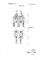
- FIG. 1 is a sectioned elevation of two-disengaged coupling halves in which the present invention is embodied;
- FIG. 2 discloses the halves of FIG. I joined and locked together
- FIG. 3 discloses the halves of FIGS. 1 and 2 locked and their valves actuated to communicate their conduit sections.
- the invention is embodied in the halves of coupling structure, each of which is permanently mounted on the end of a conduit section.
- One half is arranged to more or less fit inside the other, so they can be logically designated as male and female halves.
- Locking structure extends through the overlapping sidewalls of the halves.
- Each half has :a valve member whose passages aline to fully communicate the conduit sections through the coupling. Alternately, the valves rotate to isolate their conduits and prevent escape of fluid therefrom as well as entry of fluid thereinto.
- Both the valve structure and the locking structure are actuated by a single movable collar member on the external surface of the coupling.
- the collar is moved in substantially a straight line to actuate the locking and valve means in sequence.
- the simplicity of this single element actuation to perform multiple results requires only a simple operator. Automation of a system utilizing this coupling is the more feasible withan arrangement of this nature.
- FIG. 1 Coupling Halves Separated Conduit sections 1 and 2 are to be communicated through the novel coupling.
- Female half 3 is attached to conduit section 2 and male half 4 is attached to section I.
- the drawing discloses the halves alined, ready to engage each other to consummate the communication.
- Female half 3 comprises a base 5 which is welded, or otherwise attached, to conduit section 2. Attached to base 5 is a shoe 6 which provides a cavity 7 for a valve element 8. A face area 9 is provided on the end of shoe 6 for engagement with a similar face of the male half. Face 9 is more specifically, a shoulder within the bore 10 of shoe 6. Male half 4 fits into this bore to bring its face 11 into the engagement with face 9. A collar 12 will subsequently slide along the external wall of shoe 6 while mechanically linked with valve 8 and lock pins 13.
- Male half 4 comprises a body 14 attached to conduit section 1.
- Body 14 is externally sized for insertion within walls 10 and provides a cavity 15in which valve 16 is mounted.
- Retainer 17 on the end of body completes the mount for valve 16 and specifically provides the sealing face 11 which will be subsequently brought into engagement with the sealing face 9 of shoe 6.
- FIG. 2 Faces 9 and 11 Sealed and the Halves Locked Body 14 has been inserted into the bore of shoe 6 and faces 9 and 11 engaged.
- a form of O-ring has been disclosed to aid the sealing between these faces.
- Both valve 8 and valve 16 have a mechanical connection with collar 12.
- Pin 20 extends from valve 8 into slot 21 of collar 12.
- Pin 22 extends from valve 16 into slot 23 of collar 12.
- Pin 20 is captured permanently within slot 21 while slot 23 is open at its bottom to receive pin 22 as male half 4 is inserted in female half 3.
- FIG. 3 Halves Locked and Valves Actuated Each of valves 8 and 16 rotate within their respective heads.
- the passages of the valves are positioned 90 to the alinement requirement for straight-through communication.
- the bodies of the valves seal their cavities against transfer of fluid from their conduit sections and into their conduit sections.
- valves 8 and 16 rotate on bosses joumaled in the walls of their cavities.
- Boss 30 of valve 8 is joumaled in the wall of shoe 6 and boss 31 of valve 16 is journaled in the wall of body 14.
- Pins and 22 are mounted off center in the bosses, protruding out into grooves 21 and 23. As grooves 21, 23 are carried downward, as viewed in the drawings, they force the pins to rotate the valves 90, alining their passages in straight-through communication.
- FIG. 3 discloses this final position of collar 12, valves 8 and 16 rotated for the desired communication.
- the locking function is embodied in pins 13 positioned into indentations 27 and withdrawn therefrom. It is obvious, from inspection of FIG. 1, that the indentations have beveled sides which match complemental beveled surfaces on the ends of pins 13. Pins 13 will not maintain a locking bridge between shoe 6 and body 14 unless held in engagement with indentations 27. The heads can be pulled apart, pins 13 unseating from indentations 27, if the pins are free to move radially outward.
- valves 8 and 16 take place.
- the direction of the slots determine the desired sequence of locking and valve actuation.
- valves are generally spherical.
- the spherical surface of valve 8 rests on seal rings 35 and 36. With valve passage 37 in cavity 7, between the seal rings, conduit 2 is isolated from communication with any external fluid.
- Valve 16 is also generally spherical, sealing to rings 38 and 39. Passage 40 is also isolated in cavity 15, sealing conduit 1.
- Slot 23 is open downward, slightly funneled in shape to receive pin 22 as the halves are joined. No actuation takes place with valve 16 as collar 12 moves downward to the FIG. 2
- conduit section 2 cation between conduit section 2 and conduit section 1.
- a coupling for fluid conduit including:
- a pair of heads each of which is adapted to connect to a section of fluid conduit, arranged to contact and seal together in prevention of the transfer of fluid into and out of the conduit sections;
- locking pins positioned to extend between mating holes in each of the heads, arranged so that the collar moves and contacts the pins when the heads are in contact and retains the pins in the mating holes of the heads to mechanically lock the heads together;
- each head positioned to prevent the escape of fluid from either conduit section before the heads are locked together in their sealed engagement;
- a first pin mounted on the valve in one of the heads and captured permanently by a first groove in the collar, the first groove arranged axially with the conduit and the collar for some predetermined distance and arranged at an angle to the axis of conduit and collar for some predetermined distance;
- a second pin mounted on the valve in the other of the heads and engaged by a second groove in the collar, the second groove being open to receive the second pin when the heads are placed in contact, and the second groove arranged axially with the conduit and the collar for some predetermined distance and arranged at an angle to the axis of conduit and collar for some predetermined distance;
Description
0 United States Patent 11113,545, 490
[72] inventor Bill S. Burns [56] References Cited Tulsa, Oklahoma UNITED STATES PATENTS 1 51:1 32 1: 2,991,090 7/1961 De Cenzo 137161402 [221 Fl 9 3,301,272 1/1967 Petty 161m... l37/6i4.06 [451 Patemed 3 035 808 5/1962 Knox 166/224 [73] Assignee Combustion Engineering hm New York, New York Primary Examiner-William F. ODea a corporation of Delaware Assistant Examiner-William B. Wright Attorney-Arthur L. Wade 541 mm) CONDUIT COUPLING 1 Claim, 3 Drawing Figs.
251/ 149.2 [5]] In, (I F16k 31/523 ABSTRACT: A pair of heads, each attached to a section of [50] Field of Search l37l6l4.06, flu d conduit having movable parts which mechanically lock 6i4.02,6i4.03,6i4.04;251/1499, 149.2, 340, the heads together before valves within each head aline to 229; 166/224, 226 communicate the fluid conduit sections.
PATENIED on: 8l97fl 3 545490 SHEET 1 BF 2 INVENTOR. BILL S. BUR US ATTORNEY PATENTED um 8 I970 SHEET 2 0F 2 INVENTOR. B/L L 5. BURRUS ATTORNEY FLUID CONDUI'I COUPLING BACKGROUND OF THE INVENTION 1. Field of the Invention The present invention relates to the connection and disconnection of fluid conduits within a subsea environment. More particularly, the invention relates to couplings for conduits which seal fluids against transfer between their environment and their interior prior to communicating their conduits.
2. Description of the Prior Art The coupling art is well developed. Couplings continue to be developed for communicating conduits together. The conduits may be small, metallic tubing or large, flexible hose. It may be required to permanently connect the conduit sections through their couplings or provide for their ready disconnection.
Within the art of couplings there are peculiar requirements imposed by the hostile environment of the sea. The oil industry is demanding simple couplings which reduce to a minimum the leakage from their conduits when connection takes place and, of course, reduction to a minimum the intake of sea water. These couplings must be single enough to lend themselves to straight line actuation in automated systems.
SUMMARY OF THE INVENTION A principal object of the present invention is to seal the two halves of a coupling for conduit sections together and then communicate the conduit sections together through the coupling.
Another object is to positively lock the two halves of the coupling together before the sections are communicated.
Another object is to provide a single structure which will move in a straight line to first lock the halves in a seal and then valve the conduits into straight-through communication in sequence when the coupling is made up and then isolate the conduits before unlocking the halves when the coupling is broken down.
The present invention contemplates the two halves of a coupling to be mated formed as male and female structures whose faces are brought together to seal against the transfer of fluid across their sealing surfaces. Each half is connected to an end of a conduit section to be communicated through the coupling in a straight-through flow, and a single external collar structure is moved in a straight line to actuate locking structure and valving structure within the halves. Different positions of the collar in its straight line travel along theextemal surface of the sealed halves actuates locking structure between the halves and valves which form a straight-through passage between the conduit sections. The collar is linked to the lock and valves to first actuate the lock and then open the valves when the coupling is made up. When the coupling is to be broken down the collar causes the reverse of the sequence, first closing the valves and then unlocking the halves.
BRIEF DESCRIPTION OF THE DRAWINGS Other objects, advantages and features of this invention will become apparent to one skilled in the art upon consideration of the written specification, appended claims, and attached drawings, wherein;
FIG. 1 is a sectioned elevation of two-disengaged coupling halves in which the present invention is embodied;
FIG. 2 discloses the halves of FIG. I joined and locked together;
FIG. 3 discloses the halves of FIGS. 1 and 2 locked and their valves actuated to communicate their conduit sections.
DESCRIPTION OF THE PREFERRED EMBODIMENT General The invention is embodied in the halves of coupling structure, each of which is permanently mounted on the end of a conduit section. One half is arranged to more or less fit inside the other, so they can be logically designated as male and female halves.
Locking structure extends through the overlapping sidewalls of the halves. Each half has :a valve member whose passages aline to fully communicate the conduit sections through the coupling. Alternately, the valves rotate to isolate their conduits and prevent escape of fluid therefrom as well as entry of fluid thereinto.
Both the valve structure and the locking structure are actuated by a single movable collar member on the external surface of the coupling. The collar is moved in substantially a straight line to actuate the locking and valve means in sequence. The simplicity of this single element actuation to perform multiple results requires only a simple operator. Automation of a system utilizing this coupling is the more feasible withan arrangement of this nature.
FIG. 1 Coupling Halves Separated Conduit sections 1 and 2 are to be communicated through the novel coupling. Female half 3 is attached to conduit section 2 and male half 4 is attached to section I. The drawing discloses the halves alined, ready to engage each other to consummate the communication.
FIG. 2 Faces 9 and 11 Sealed and the Halves Locked Body 14 has been inserted into the bore of shoe 6 and faces 9 and 11 engaged. A form of O-ring has been disclosed to aid the sealing between these faces.
There is a very small, insignificant cavity remaining between the valves 8 and 16 and within the coupling. When the halves are brought together beneaththe surface of the sea, a small amount of this sea water remains within the coupling to find its way into the conduits. However, this cavity and the volume of sea water trapped during make up, is not large enough to be of any importance to the operation of the systems utilizing the fluid of the conduits connected with the coupling.
Both valve 8 and valve 16 have a mechanical connection with collar 12. Pin 20 extends from valve 8 into slot 21 of collar 12. Pin 22 extends from valve 16 into slot 23 of collar 12. Pin 20 is captured permanently within slot 21 while slot 23 is open at its bottom to receive pin 22 as male half 4 is inserted in female half 3. When collar 12 completely reciprocates along the outside of the shoe 6, valves 8 and 16 will be actu- The halves being sealed and locked together, the collar is next used to actuate valves 8 and 16 to aline their passages in a straight-through connection of conduits 1 and 2. A continuation of the travel of collar 12 will carry out the actuation and open valves 8 and 16 after the sealing and locking of FIG. 2 has taken place.
FIG. 3 Halves Locked and Valves Actuated Each of valves 8 and 16 rotate within their respective heads. In FIGS. 1 and 2, the passages of the valves are positioned 90 to the alinement requirement for straight-through communication. When positioned as disclosed in FIGS. 1 and 2, the bodies of the valves seal their cavities against transfer of fluid from their conduit sections and into their conduit sections.
Each of thetwo valves 8 and 16 rotate on bosses joumaled in the walls of their cavities. Boss 30 of valve 8 is joumaled in the wall of shoe 6 and boss 31 of valve 16 is journaled in the wall of body 14. Pins and 22 are mounted off center in the bosses, protruding out into grooves 21 and 23. As grooves 21, 23 are carried downward, as viewed in the drawings, they force the pins to rotate the valves 90, alining their passages in straight-through communication. FIG. 3 discloses this final position of collar 12, valves 8 and 16 rotated for the desired communication.
Conclusion General reference has been made to the cooperation of the coupling structures. Once female half 3 has male half 4 inserted, collar 12 moves along their outside to first lock the halves together and then actuate the valve elements 8 and 16 to provide unobstructed straight-through flow of fluids between conduit sections 1 and 2.
The locking function is embodied in pins 13 positioned into indentations 27 and withdrawn therefrom. It is obvious, from inspection of FIG. 1, that the indentations have beveled sides which match complemental beveled surfaces on the ends of pins 13. Pins 13 will not maintain a locking bridge between shoe 6 and body 14 unless held in engagement with indentations 27. The heads can be pulled apart, pins 13 unseating from indentations 27, if the pins are free to move radially outward.
Surface of collar 12 will hold pins 13 in place. When collar 12 is moved to the FIG. 2 position, the pins cannot retract and the heads are thereby locked together.
It is while the heads are locked together that actuation of valves 8 and 16 take place. The direction of the slots determine the desired sequence of locking and valve actuation.
In the drawings it is evident from inspection that the valves are generally spherical. The spherical surface of valve 8 rests on seal rings 35 and 36. With valve passage 37 in cavity 7, between the seal rings, conduit 2 is isolated from communication with any external fluid.
Movement of collar 12 downward to the FIG. 2 position does not actuate valve 8. Pin 20 simply moves up the vertical portions of slot 21 while surface 25 is moved into a locking position over pins 13. It is the next part of the downward travel of collar 12 which actuates valve 8.
Actuation of valve 8 takes place at the same time valve 16 is actuated. Valve 16 is also generally spherical, sealing to rings 38 and 39. Passage 40 is also isolated in cavity 15, sealing conduit 1.
cation between conduit section 2 and conduit section 1.
As the collar 12 is moved from the FIG. 3 position to the FIG. 2 position, the slots actuate the valves to close. The FIG. 1 position is then assumed and the heads unlock with no transfer of fluid between the conduits and their environment.
From the foregoing it will be seen that this invention is one well adapted to attain all of the ends and objects hereinabove set forth, together with other advantages which are obvious and which are inherent to the apparatus.
It will be understood that certain features and subcombinations are of utility and may be employed without reference to other features and subcombinations. This is contemplated by and is within the scope of the invention.
As many possible embodiments may be made of the invention without departing from the scope thereof, it is to be understood that all matter herein set forth or shown in the accompanying drawings is to be interpreted as illustrative and not in a limiting sense.
Iclaim:
l. A coupling for fluid conduit, including:
a pair of heads, each of which is adapted to connect to a section of fluid conduit, arranged to contact and seal together in prevention of the transfer of fluid into and out of the conduit sections;
an actuating collar movable only in a straight line along the outside of the heads;
locking pins positioned to extend between mating holes in each of the heads, arranged so that the collar moves and contacts the pins when the heads are in contact and retains the pins in the mating holes of the heads to mechanically lock the heads together;
a valve in each head positioned to prevent the escape of fluid from either conduit section before the heads are locked together in their sealed engagement;
a first pin mounted on the valve in one of the heads and captured permanently by a first groove in the collar, the first groove arranged axially with the conduit and the collar for some predetermined distance and arranged at an angle to the axis of conduit and collar for some predetermined distance;
a second pin mounted on the valve in the other of the heads and engaged by a second groove in the collar, the second groove being open to receive the second pin when the heads are placed in contact, and the second groove arranged axially with the conduit and the collar for some predetermined distance and arranged at an angle to the axis of conduit and collar for some predetermined distance;
whereby the groove-and-pin linkage connecting the actuating collar and valves serially locks the heads together over the axial travel portion of the pins in the grooves and actuates the valves in each head over the angled travel portion of the pins in the grooves, the actuating collar moving in a straight line to establish communication between the fluid conduit section; and
whereby substantially no transfer of fluid between the conduit and the environment thereof is experienced during either the coupling or uncoupling of the conduit.
Applications Claiming Priority (1)
| Application Number | Priority Date | Filing Date | Title |
|---|---|---|---|
| US67441067A | 1967-10-11 | 1967-10-11 |
Publications (1)
| Publication Number | Publication Date |
|---|---|
| US3545490A true US3545490A (en) | 1970-12-08 |
Family
ID=24706486
Family Applications (1)
| Application Number | Title | Priority Date | Filing Date |
|---|---|---|---|
| US3545490D Expired - Lifetime US3545490A (en) | 1967-10-11 | 1967-10-11 | Fluid conduit coupling |
Country Status (1)
| Country | Link |
|---|---|
| US (1) | US3545490A (en) |
Cited By (31)
| Publication number | Priority date | Publication date | Assignee | Title |
|---|---|---|---|---|
| US4335747A (en) * | 1979-10-26 | 1982-06-22 | Aisin Seiki Kabushiki Kaisha | Connecting device for conduits |
| FR2657940A1 (en) * | 1990-02-08 | 1991-08-09 | Staubli Sa Ets | PIPE TYPE CONNECTION WITH ROTATING VALVES. |
| US5083588A (en) * | 1990-05-18 | 1992-01-28 | S.A. Des Etablissements Staubli (France) | Device, incorporating rotating valves, for coupling pipes |
| WO1993010327A1 (en) * | 1991-11-11 | 1993-05-27 | Alpha Thames Engineering Limited | Two-part connector for fluid carrying conduits |
| US5286129A (en) * | 1991-08-07 | 1994-02-15 | Crater Corporation | Coupling device and methods of coupling |
| US5915402A (en) * | 1998-09-21 | 1999-06-29 | Mitchell, Ii; William G. | Refrigeration isolation valve apparatus and method of use |
| US7448653B2 (en) | 2005-06-10 | 2008-11-11 | Value Plastics, Inc. | Female connector for releasable coupling with a male connector defining a fluid conduit |
| US7806139B2 (en) | 2006-01-20 | 2010-10-05 | Value Plastics, Inc. | Fluid conduit coupling assembly having male and female couplers with integral valves |
| USD629894S1 (en) | 2008-07-03 | 2010-12-28 | Value Plastics, Inc. | Male body of connector for fluid tubing |
| USD630320S1 (en) | 2008-07-03 | 2011-01-04 | Value Plastics, Inc. | Connector for fluid tubing |
| US7878553B2 (en) | 2003-09-12 | 2011-02-01 | Value Plastics, Inc. | Releasable connection assembly for joining tubing sections |
| USD634840S1 (en) | 2008-07-03 | 2011-03-22 | Value Plastics, Inc. | Female body of connector for fluid tubing |
| USD645547S1 (en) | 2007-11-19 | 2011-09-20 | Value Plastics, Inc. | Male quick connect fitting |
| USD649240S1 (en) | 2009-12-09 | 2011-11-22 | Value Plastics, Inc. | Male dual lumen bayonet connector |
| USD650478S1 (en) | 2009-12-23 | 2011-12-13 | Value Plastics, Inc. | Female dual lumen connector |
| USD652511S1 (en) | 2011-02-11 | 2012-01-17 | Value Plastics, Inc. | Female body of connector for fluid tubing |
| USD652510S1 (en) | 2011-02-11 | 2012-01-17 | Value Plastics, Inc. | Connector for fluid tubing |
| EP2423555A1 (en) * | 2009-03-14 | 2012-02-29 | H & B Electronic GmbH & Co. KG | Coupling assembly |
| USD655393S1 (en) | 2009-06-23 | 2012-03-06 | Value Plastics, Inc. | Multi-port valve |
| USD663022S1 (en) | 2011-02-11 | 2012-07-03 | Nordson Corporation | Male body of connector for fluid tubing |
| US8235426B2 (en) | 2008-07-03 | 2012-08-07 | Nordson Corporation | Latch assembly for joining two conduits |
| USD698440S1 (en) | 2011-07-29 | 2014-01-28 | Nordson Corporation | Connector for fluid tubing |
| USD699840S1 (en) | 2011-07-29 | 2014-02-18 | Nordson Corporation | Male body of connector for fluid tubing |
| USD699841S1 (en) | 2011-07-29 | 2014-02-18 | Nordson Corporation | Female body of connector for fluid tubing |
| USD709612S1 (en) | 2011-12-23 | 2014-07-22 | Nordson Corporation | Female dual lumen connector |
| US9046205B2 (en) | 2009-12-09 | 2015-06-02 | Nordson Corporation | Fluid connector latches with profile lead-ins |
| US9388929B2 (en) | 2009-12-09 | 2016-07-12 | Nordson Corporation | Male bayonet connector |
| US9464741B2 (en) | 2009-12-09 | 2016-10-11 | Nordson Corporation | Button latch with integrally molded cantilever springs |
| USD785790S1 (en) | 2009-12-09 | 2017-05-02 | General Electric Company | Male dual lumen bayonet connector |
| USD838366S1 (en) | 2016-10-31 | 2019-01-15 | Nordson Corporation | Blood pressure connector |
| US10711930B2 (en) | 2009-12-09 | 2020-07-14 | Nordson Corporation | Releasable connection assembly |
-
1967
- 1967-10-11 US US3545490D patent/US3545490A/en not_active Expired - Lifetime
Cited By (46)
| Publication number | Priority date | Publication date | Assignee | Title |
|---|---|---|---|---|
| US4335747A (en) * | 1979-10-26 | 1982-06-22 | Aisin Seiki Kabushiki Kaisha | Connecting device for conduits |
| FR2657940A1 (en) * | 1990-02-08 | 1991-08-09 | Staubli Sa Ets | PIPE TYPE CONNECTION WITH ROTATING VALVES. |
| EP0441727A1 (en) * | 1990-02-08 | 1991-08-14 | S.A. DES ETABLISSEMENTS STAUBLI (France) | Conduit connection with rotatable shut-off elements |
| US5083588A (en) * | 1990-05-18 | 1992-01-28 | S.A. Des Etablissements Staubli (France) | Device, incorporating rotating valves, for coupling pipes |
| US5286129A (en) * | 1991-08-07 | 1994-02-15 | Crater Corporation | Coupling device and methods of coupling |
| WO1993010327A1 (en) * | 1991-11-11 | 1993-05-27 | Alpha Thames Engineering Limited | Two-part connector for fluid carrying conduits |
| US5494110A (en) * | 1991-11-11 | 1996-02-27 | Alpha Thames Engineering Limited | Two-part connector for fluid carrying conduits |
| US5915402A (en) * | 1998-09-21 | 1999-06-29 | Mitchell, Ii; William G. | Refrigeration isolation valve apparatus and method of use |
| US7878553B2 (en) | 2003-09-12 | 2011-02-01 | Value Plastics, Inc. | Releasable connection assembly for joining tubing sections |
| US7448653B2 (en) | 2005-06-10 | 2008-11-11 | Value Plastics, Inc. | Female connector for releasable coupling with a male connector defining a fluid conduit |
| US7770939B2 (en) | 2005-06-10 | 2010-08-10 | Value Plastics, Inc. | Female connector for releasable coupling with a male connector defining a fluid conduit |
| US8113546B2 (en) | 2005-06-10 | 2012-02-14 | Value Plastics, Inc. | Latching female fluid tubing coupler |
| US7806139B2 (en) | 2006-01-20 | 2010-10-05 | Value Plastics, Inc. | Fluid conduit coupling assembly having male and female couplers with integral valves |
| US8397756B2 (en) | 2006-01-20 | 2013-03-19 | Nordson Corporation | Fluid conduit couplers with depressible latch mechanism |
| USD645547S1 (en) | 2007-11-19 | 2011-09-20 | Value Plastics, Inc. | Male quick connect fitting |
| USD654573S1 (en) | 2007-11-19 | 2012-02-21 | Value Plastics, Inc. | Female quick connect fitting |
| USD630320S1 (en) | 2008-07-03 | 2011-01-04 | Value Plastics, Inc. | Connector for fluid tubing |
| USD634840S1 (en) | 2008-07-03 | 2011-03-22 | Value Plastics, Inc. | Female body of connector for fluid tubing |
| US8596688B2 (en) | 2008-07-03 | 2013-12-03 | Nordson Corporation | Latch assembly for joining two conduits |
| US8448994B2 (en) | 2008-07-03 | 2013-05-28 | Nordson Corporation | Latch assembly for joining two conduits |
| US8235426B2 (en) | 2008-07-03 | 2012-08-07 | Nordson Corporation | Latch assembly for joining two conduits |
| USD629894S1 (en) | 2008-07-03 | 2010-12-28 | Value Plastics, Inc. | Male body of connector for fluid tubing |
| EP2423555A1 (en) * | 2009-03-14 | 2012-02-29 | H & B Electronic GmbH & Co. KG | Coupling assembly |
| USD655393S1 (en) | 2009-06-23 | 2012-03-06 | Value Plastics, Inc. | Multi-port valve |
| US9732891B2 (en) | 2009-12-09 | 2017-08-15 | General Electric Company | Male bayonet connector |
| USD785790S1 (en) | 2009-12-09 | 2017-05-02 | General Electric Company | Male dual lumen bayonet connector |
| US9388929B2 (en) | 2009-12-09 | 2016-07-12 | Nordson Corporation | Male bayonet connector |
| USD649240S1 (en) | 2009-12-09 | 2011-11-22 | Value Plastics, Inc. | Male dual lumen bayonet connector |
| US9046205B2 (en) | 2009-12-09 | 2015-06-02 | Nordson Corporation | Fluid connector latches with profile lead-ins |
| US10711930B2 (en) | 2009-12-09 | 2020-07-14 | Nordson Corporation | Releasable connection assembly |
| US9464741B2 (en) | 2009-12-09 | 2016-10-11 | Nordson Corporation | Button latch with integrally molded cantilever springs |
| US10001236B2 (en) | 2009-12-09 | 2018-06-19 | General Electric Company | Male bayonet connector |
| USD650478S1 (en) | 2009-12-23 | 2011-12-13 | Value Plastics, Inc. | Female dual lumen connector |
| USD652510S1 (en) | 2011-02-11 | 2012-01-17 | Value Plastics, Inc. | Connector for fluid tubing |
| USD663022S1 (en) | 2011-02-11 | 2012-07-03 | Nordson Corporation | Male body of connector for fluid tubing |
| USD652511S1 (en) | 2011-02-11 | 2012-01-17 | Value Plastics, Inc. | Female body of connector for fluid tubing |
| USD699840S1 (en) | 2011-07-29 | 2014-02-18 | Nordson Corporation | Male body of connector for fluid tubing |
| USD712537S1 (en) | 2011-07-29 | 2014-09-02 | Nordson Corporation | Connector for fluid tubing |
| USD699841S1 (en) | 2011-07-29 | 2014-02-18 | Nordson Corporation | Female body of connector for fluid tubing |
| USD698440S1 (en) | 2011-07-29 | 2014-01-28 | Nordson Corporation | Connector for fluid tubing |
| USD709612S1 (en) | 2011-12-23 | 2014-07-22 | Nordson Corporation | Female dual lumen connector |
| USD967955S1 (en) | 2016-10-31 | 2022-10-25 | Nordson Corporation | Blood pressure connector |
| USD838366S1 (en) | 2016-10-31 | 2019-01-15 | Nordson Corporation | Blood pressure connector |
| USD961070S1 (en) | 2016-10-31 | 2022-08-16 | Nordson Corporation | Blood pressure connector |
| USD964558S1 (en) | 2016-10-31 | 2022-09-20 | Nordson Corporation | Blood pressure connector |
| USD964557S1 (en) | 2016-10-31 | 2022-09-20 | Nordson Corporation | Blood pressure connector |
Similar Documents
| Publication | Publication Date | Title |
|---|---|---|
| US3545490A (en) | Fluid conduit coupling | |
| US7159616B2 (en) | Dual path hydraulic coupling | |
| US10156114B2 (en) | Poppet assembly for use in a subsea connection system | |
| US9617819B2 (en) | Subsea collet connection system | |
| US4834139A (en) | Radial seal hydraulic coupler | |
| US3680591A (en) | Unique hydraulic coupler | |
| US3191972A (en) | Quick connect tube coupling having locking means with visual indicator | |
| US4768538A (en) | Radial seal hydraulic coupler | |
| US3291152A (en) | Self sealing quick disconnect coupling | |
| US4438779A (en) | Ball valve coupling | |
| US2991090A (en) | Valved coupling | |
| US5014743A (en) | Double-pipe pipe coupling | |
| RU2553675C2 (en) | Valve assembly | |
| JPS62266278A (en) | Poppet valve | |
| BR0101219B1 (en) | underwater hydraulic connection. | |
| JPS61180091A (en) | Automatic blocking joint | |
| US3466001A (en) | Subsea valve and valve operator assembly | |
| US4469136A (en) | Subsea flowline connector | |
| US4549577A (en) | Female coupler for a fluid circuit | |
| US4799512A (en) | Coupling assembly | |
| US5129417A (en) | Valve including a closing device and sealed connectors | |
| EP0681137B1 (en) | Subsea fluid coupling employing metal-to-metal sealing | |
| US3536344A (en) | Subsea valve and valve operator assembly | |
| US2854258A (en) | Self-sealing coupling | |
| PL189386B1 (en) | Application of valve actuator |
Legal Events
| Date | Code | Title | Description |
|---|---|---|---|
| AS | Assignment |
Owner name: NATIONAL TANK COMPANY, OKLAHOMA Free format text: ASSIGNMENT OF ASSIGNORS INTEREST;ASSIGNOR:COMBUSTION ENGINEERING, INC., A CORP OF DE.;REEL/FRAME:004561/0890 Effective date: 19860210 Owner name: NATIONAL TANK COMPANY, 5330 EAST 31ST STREET, TULS Free format text: ASSIGNMENT OF ASSIGNORS INTEREST.;ASSIGNOR:COMBUSTION ENGINEERING, INC., A CORP OF DE.;REEL/FRAME:004561/0890 Effective date: 19860210 |